WO2024248072A1 - 壁構造 - Google Patents
壁構造 Download PDFInfo
- Publication number
- WO2024248072A1 WO2024248072A1 PCT/JP2024/019818 JP2024019818W WO2024248072A1 WO 2024248072 A1 WO2024248072 A1 WO 2024248072A1 JP 2024019818 W JP2024019818 W JP 2024019818W WO 2024248072 A1 WO2024248072 A1 WO 2024248072A1
- Authority
- WO
- WIPO (PCT)
- Prior art keywords
- wall
- joint
- wall material
- materials
- base
- Prior art date
- Legal status (The legal status is an assumption and is not a legal conclusion. Google has not performed a legal analysis and makes no representation as to the accuracy of the status listed.)
- Ceased
Links
Images


Classifications
-
- E—FIXED CONSTRUCTIONS
- E04—BUILDING
- E04F—FINISHING WORK ON BUILDINGS, e.g. STAIRS, FLOORS
- E04F13/00—Coverings or linings, e.g. for walls or ceilings
- E04F13/07—Coverings or linings, e.g. for walls or ceilings composed of covering or lining elements; Sub-structures therefor; Fastening means therefor
- E04F13/08—Coverings or linings, e.g. for walls or ceilings composed of covering or lining elements; Sub-structures therefor; Fastening means therefor composed of a plurality of similar covering or lining elements
Definitions
- the present invention relates to a wall structure used as a wall for buildings and structures, and more specifically, to a wall structure with wall materials installed in a staggered pattern.
- Patent Document 1 discloses an exterior wall structure in which multiple rectangular exterior wall materials are butted up, down, left and right. This exterior wall structure does not require sealing (caulking) materials.
- a pair of left and right exterior wall materials are arranged on the upper side, and a pair of left and right exterior wall materials are arranged below them, and these two pairs of exterior wall materials are fixed to the wall base by mounting fixtures provided at the cross-shaped intersection.
- the mounting fixtures are equipped with upper support pieces that support the lower ends of the pair of upper left and right exterior wall materials, and lower engagement pieces that engage with the upper ends of the pair of lower left and right exterior wall materials, and further equipped with a lateral displacement prevention part that is arranged between the pair of lower left and right exterior wall materials and prevents the pair of exterior wall materials from shifting left and right.
- a solid portion is formed at both the left and right ends of each exterior wall material to join with the adjacent exterior wall material in the left-right direction.
- a receiving solid portion is formed at the right end of each exterior wall material, which is offset toward the back surface
- a pressing solid portion is formed at the left end, which is offset toward the front surface and presses down on the receiving solid portion.
- a water-stopping material is provided on the surface of this pressing solid portion so that it extends in the vertical direction.
- the object of the present invention is to provide a wall structure that does not use sealing materials.
- a wall structure is a wall structure in which wall materials are installed in an area partitioned by joints extending vertically and horizontally, the joints having non-cross joint portions including at least one of a T-shaped joint portion and an L-shaped joint portion, the non-cross joint portion including a horizontal joint portion extending horizontally and an upper-lower joint portion extending vertically, the upper-lower joint portion being formed between a pair of wall materials adjacent to the left and right, and a joint material is provided.
- the wall structure according to one aspect of the present invention is a wall structure in which a left-right joint portion extending left and right and an upper-lower joint portion extending continuously at least up and down are formed by a plurality of wall materials arranged up, down, left and right on a wall base, and a waterproofing member is provided in the upper and lower joint portions, the waterproofing member comprising a water-stopping material that contacts the back surfaces of the plurality of wall materials, and the water-stopping material is provided so as to surround the upper and lower joint portions in a front view.
- FIG. 1 is a perspective view showing a first embodiment of a wall structure according to the present invention.
- FIG. 2 is a perspective view showing a construction process of the first embodiment of the wall structure according to the present invention.
- FIG. 3 is a perspective view showing a construction process of the first embodiment of the wall structure according to the present invention.
- FIG. 4 is a perspective view showing a construction process of the first embodiment of the wall structure according to the present invention.
- FIG. 5 is a perspective view showing a construction process of the first embodiment of the wall structure according to the present invention.
- FIG. 6 is a perspective view showing a construction process of the first embodiment of the wall structure according to the present invention.
- FIG. 7 is a cross-sectional view showing a construction state of the first embodiment of the wall structure according to the present invention.
- FIG. 8 is a front view showing a construction process of the first embodiment of the wall structure according to the present invention.
- FIG. 9 is a front view showing a construction process of the first embodiment of the wall structure according to the present invention.
- FIG. 10 is a schematic diagram showing a modification of the first embodiment of the wall structure according to the present invention.
- FIG. 11 is a schematic diagram showing a first embodiment of a wall structure according to the present invention.
- FIG. 12 is a schematic diagram showing a second embodiment of a wall structure according to the present invention.
- FIG. 13 is a perspective view showing a wall structure according to the third embodiment.
- FIG. 14 is a cross-sectional view of the same.
- FIG. 15A is a perspective view showing the waterproofing member of the same
- FIG 15B is an enlarged side view showing an upper part of the same waterproofing member
- FIG 15C is an enlarged side view showing a lower part of the same waterproofing member.
- Fig. 16A is a perspective view showing a connection between the waterproof member and the starter of the same
- Fig. 16B is a cross-sectional view of the lower part of the same.
- FIG. 17 is a perspective view showing the construction process of the above.
- FIG. 18 is a perspective view showing the construction process of the above.
- FIG. 19 is a perspective view showing the construction process of the above.
- FIG. 20 is a perspective view showing the construction process of the above.
- FIG. 21 is a perspective view showing the construction process of the above.
- FIG. 22 is a perspective view showing the construction process of the above.
- FIG. 23 is a perspective view showing a construction process of a wall structure according to the fourth embodiment.
- FIG. 24 is a perspective view showing the construction process of the above.
- FIG. 25 is a perspective view showing the construction process of the above.
- FIG. 26 is a perspective view showing the construction process of the above.
- FIG. 27 is a perspective view showing the construction process of the above.
- FIG. 28 is a perspective view showing the construction process of the above.
- FIG. 29 is a perspective view showing a wall structure according to the fifth embodiment.
- FIG. 30 is a cross-sectional view of the same.
- FIG. 31 is a cross-sectional view of the same.
- FIG. 32 is a perspective view showing a wall structure according to the sixth embodiment.
- FIG. 33 is a cross-sectional view of the same.
- FIG. 34 is a cross-sectional view of the same.
- FIG. 35 is a perspective view showing a wall structure according to the seventh embodiment.
- FIG. 36 is a cross-sectional view of the same.
- FIG. 37 is a cross-sectional view of the same.
- FIG. 38 is a perspective view showing another waterproof member.
- the wall structure 1 of this embodiment is a wall structure 1 constructed in a horse-lined manner.
- the horse-lined wall structure 1 is constructed by arranging a plurality of wall materials 2 in a staggered manner. That is, a plurality of wall materials 2 arranged in the left-right direction and a plurality of wall materials 2 arranged in the left-right direction above them are constructed with a shift of about half a degree in the left-right direction. Therefore, in the wall structure 1 of this embodiment, a straight joint is not formed in the vertical direction on the wall surface.
- the wall structure 1 of this embodiment has joint material 4 applied to the joints 3 between the wall materials 2 lined up in the left-right direction. Therefore, the joint material 4 in the joints 3 can reduce the amount of water that penetrates the joints 3, and can prevent water from adhering to the back surface of the wall material 2 through the joints 3. Moreover, the joint material 4 can guide the water downward so that it flows down. This makes it possible to achieve both a simple wall material shape and waterproofing, resulting in a wall structure 1 that does not use a sealant.
- the term “forward” refers to the direction from inside the building to the outside.
- the term “backward” refers to the direction from outside the building to inside.
- the term “upward” refers to the vertical upward direction, and the term “downward” refers to the vertical downward direction.
- the term “leftward” refers to the direction perpendicular to the front-to-back direction and the up-to-down direction, and refers to the direction toward the left when the wall structure 1 is viewed from the front.
- the term “rightward” refers to the direction perpendicular to the front-to-back direction and the up-to-down direction, and refers to the direction toward the right when the wall structure 1 is viewed from the front.
- the wall structure 1 is an exterior wall of a building.
- the wall structure 1 includes a pillar 11, a wall base 12, a wall material fastener 13, a wall material 2, and a joint material 4.
- Figure 1 shows a wooden building that uses wooden pillars 11. Multiple pillars 11 are arranged side-by-side on a base 14.
- the wall base 12 is planar (the surface facing the exterior is flat) and comprises multiple support surface materials 120, blocking materials 121, and sheet materials 122.
- the support surface materials 120 are formed in the shape of rectangular plates.
- the support surface materials 120 are formed, for example, from plywood, medium density fiberboard (MDF), gypsum board, etc.
- Multiple support surface materials 120 are arranged in front of the columns 11 (on the exterior side), and are fixed across the multiple columns 11 with fasteners such as nails.
- the multiple support surface materials 120 are arranged in a line in the vertical direction, and the upper and lower ends of adjacent support surface materials 120 in the vertical direction are butted together.
- the blocking material 121 is provided at the butt joints of the vertically adjacent support surface materials 120.
- the blocking material 121 blocks the gaps between the butt joints of the vertically adjacent support surface materials 120.
- the sheet material 122 is provided on the front surface (outdoor side) of the support surface material 120.
- the sheet material 122 is, for example, a moisture-permeable waterproof sheet.
- Multiple wall material fasteners 13 are provided on the front surface (outdoor side) of the wall base 12.
- the multiple wall material fasteners 13 are arranged on the front surface of the sheet material 122 and are fixed to the support surface material 120 and the pillars 11 with fasteners such as nails.
- Multiple wall materials 2 are provided on the front side (outdoor side) of the wall base 12.
- the multiple wall materials 2 are arranged in a staggered pattern. This forms a horse-lined exterior wall.
- ceramic siding material can be used as the wall material 2.
- the wall material 2 is formed in a rectangular plate shape.
- a receiving portion 21 is formed at the upper end of the wall material 2, and a pressing portion 22 is formed at the lower end.
- the receiving portion 21 protrudes above the plate-shaped portion 20 of the wall material 2, and is formed over the entire length of the wall material 2 in the left-right direction.
- the pressing portion 22 protrudes below the plate-shaped portion 20 of the wall material 2, and is formed over the entire length of the wall material 2 in the left-right direction.
- the surface of the plate-shaped portion 20 may be flat, or may have an uneven pattern formed thereon.
- the wall material 2 further includes a locking portion 23.
- the locking portion 23 protrudes below the plate-shaped portion 20 at the rear (indoor side) of the pressing portion 22, and is formed over the entire length of the wall material 2 in the left-right direction.
- the wall material 2 is attached to the front (outdoor side) of the wall base 12 with the receiving portion 21 and the locking portion 23 hooked onto the wall material fastener 13.
- a joint 3 is formed between the side ends of the wall materials 2 lined up in the left-right direction.
- the joint material 4 is a metal or plastic member, and is formed so that the vertical dimension is longer than the horizontal dimension.
- the joint material 4 is formed with a roughly T-shaped cross section. That is, the joint material 4 has a joint insertion portion 40 and a pair of insertion portions 41, 42.
- One of the insertion portions 41 protrudes in one left-right direction from the rear end (indoor end) of the joint insertion portion 40.
- the other insertion portion 42 protrudes in the other left-right direction from the rear end (indoor end) of the joint insertion portion 40.
- the insertion portion 41 and the insertion portion 42 protrude in opposite left-right directions from the joint insertion portion 40.
- the joint insertion portion 40 and one of the insertion portions 41 are at approximately a right angle, and the joint insertion portion 40 and the other insertion portion 42 are also at approximately a right angle.
- the joint material 4 has a joint insertion portion 40 disposed within the joint 3.
- One insertion portion 41 is disposed on the rear side (indoor side) of one of the wall materials 2 arranged in the left-right direction
- the other insertion portion 42 is disposed on the rear side (indoor side) of the other of the wall materials 2 arranged in the left-right direction.
- the wall structure 1 of this embodiment is constructed as follows.
- a wall material 2 (this wall material 2 is referred to as wall material 2a to distinguish it from other wall materials 2) is attached to the front side (outdoor side) of the wall base 12.
- the wall material 2a is attached by a plurality of wall material fasteners 13 (this wall material fastener 13 is referred to as wall material fasteners 13a, 13b to distinguish it from other wall material fasteners 13).
- the interval P between the plurality of wall material fasteners 13a, 13b can be, for example, 16 inches or less.
- the wall material fastener 13b is also positioned a predetermined distance S away from the connection position M1 of the plurality of wall materials 2b, 2c attached to the upper stage of the wall material 2a.
- connection position M1 corresponds to the position where the joint 3 is formed.
- the predetermined distance S can be, for example, about 2 inches. In this way, the wall material fastener 13b is positioned at a position that does not overlap with the insertion portion 41 of the joint material 4.
- the wall material fastener 13 (13a, 13b) has a fixing portion 130, an upper locking piece 131 and a lower locking piece 132.
- the fixing portion 130 is formed in a plate shape extending in the left-right direction.
- the upper locking piece 131 is provided so as to protrude from the fixing portion 130 to the front side (outdoor side).
- the front end of the upper locking piece 131 protrudes diagonally upward.
- the lower locking pieces 132 are formed in multiples (two pieces) lined up in the left-right direction and are provided so as to protrude from the fixing portion 130 to the front side (outdoor side), and the front end of the lower locking piece 132 protrudes downward.
- the wall material fasteners 13a and 13b are positioned on the front side (outdoor side) of the wall base 12. Also, by hooking the lower locking pieces 132 of the wall material fasteners 13a and 13b onto the receiving portion 21 of the wall material 2a, the wall material 2a is positioned on the front side (outdoor side) of the wall base 12.
- wall material 2 (this wall material 2 will be referred to as wall material 2b to distinguish it from the other wall materials 2) is attached to the front side (outdoor side) of the wall base 12.
- Wall material 2b is attached with multiple wall material fasteners 13 (this wall material fastener 13 will be referred to as wall material fasteners 13c, 13d to distinguish it from the other wall material fasteners 13).
- One side end 25 in the left-right direction (the right side) of wall material 2b is positioned substantially along connection position M1.
- Wall material 2b is positioned on the upper level of wall material 2a.
- the pressing part 22 of the upper wall material 2b is disposed in front of (on the outside) the receiving part 21 of the lower wall material 2a. Therefore, the pressing part 22 of the upper wall material 2b and the receiving part 21 of the lower wall material 2a are disposed opposite each other.
- the locking part 23 of the upper wall material 2b is hooked onto the upper locking pieces 131 of the wall material fasteners 13a and 13b that hold the lower wall material 2a.
- a waterproof material 29 made of a hot melt material or the like is provided on the front surface of the receiving part 21. The waterproof material 29 contacts the rear surface of the pressing part 22 that faces the receiving part 21. This improves the waterproofing between the receiving part 21 and the pressing part 22.
- the multiple wall material fasteners 13c, 13d are arranged at the same interval P as above. Also, the wall material fastener 13d close to the connection position M1 is arranged a specified distance S away from the connection position M1 as above. As above, the wall material fasteners 13c, 13d are arranged on the front side (outdoor side) of the wall base 12 by fixing the fixing parts 130 to the wall base 12 and the pillar 11 with fixing devices 133 such as screws or nails. Also, the wall material 2b is arranged on the front side (outdoor side) of the wall base 12 by hooking the lower retaining pieces 132 of the wall material fasteners 13c, 13d onto the receiving part 21 of the wall material 2b.
- the joint material 4 is placed as shown in Figure 4.
- the joint insertion portion 40 of the joint material 4 is placed approximately along the connection position M1.
- the joint material 4 is also placed so that one insertion portion 41 is inserted between the wall material 2b and the wall base 12.
- One insertion portion 41 is inserted from the side end portion 25 on the connection position M1 side of the wall material 2b.
- the side surface (left surface) of the joint insertion portion 40 is placed in contact with or close to the side end portion 25.
- the other insertion portion 42 is fixed to the wall base 12 with a fastener 45 such as a nail or screw.
- the lower wall material 2a is further fixed by another wall material fastener 13 (this wall material fastener 13 is referred to as wall material fastener 13e to distinguish it from the other wall material fasteners 13).
- the wall material fastener 13e is arranged to the side (right side) of the other insertion portion 42 of the joint material 4.
- the wall material fastener 13e is arranged so that the lower engaging piece 132 is hooked onto the receiving portion 21 of the wall material 2a and the fixing portion 130 is fixed to the wall base 12.
- the wall material fastener 13e is also fixed at a position that does not overlap with the insertion portion 42 of the joint material 4.
- the lower tier wall material 2a is further fixed by other wall material fasteners 13 (wall material fasteners 13f and 13g are used to distinguish this wall material fastener 13 from the other wall material fasteners 13).
- Wall material fasteners 13e, 13f and 13g are arranged at the same interval P as above.
- Wall material fastener 13g is also arranged a specified distance S away from connection position M2 of wall material 2c attached to the upper tier of wall material 2a. Connection position M2 corresponds to the position where joint 3 is formed.
- another wall material 2 (this wall material 2 will be referred to as wall material 2c to distinguish it from the other wall materials 2) is attached to the front side (outdoor side) of the wall base 12.
- Wall material 2c is attached with a number of wall material fasteners 13 (this wall material fastener 13 will be referred to as wall material fasteners 13h, 13i, 13j to distinguish it from the other wall material fasteners 13).
- One side end 25 in the left-right direction (the right side) of wall material 2c is positioned substantially along connection position M2.
- Wall material 2c is positioned on the upper level of wall material 2a.
- the pressing portion 22 of the upper wall material 2c is positioned in front of (on the outside) the receiving portion 21 of the lower wall material 2a. Therefore, the pressing portion 22 of the upper wall material 2c and the receiving portion 21 of the lower wall material 2a are positioned opposite each other.
- the locking portion 23 of the upper wall material 2c is hooked onto the upper locking pieces 131 of the wall material fasteners 13e, 13f, and 13g that hold the lower wall material 2a.
- the multiple wall material fasteners 13h, 13i, 13j are arranged at the same interval P as above. Also, the wall material fastener 13j close to the connection position M2 is arranged a specified distance S away from the connection position M2 as above. As above, the wall material fasteners 13h, 13i, 13j are arranged on the front side (outdoor side) of the wall base 12 by fixing the fixing parts 130 to the wall base 12 and the pillars 11 with fixing devices 133 such as screws or nails. Also, the wall material 2c is arranged on the front side (outdoor side) of the wall base 12 by hooking the lower retaining pieces 132 of the wall material fasteners 13h, 13i, 13j to the receiving parts 21 of the wall material 2c.
- a joint 3 is formed between wall material 2b and wall material 2c thus constructed. That is, the right surface of wall material 2b and the left surface of wall material 2c are arranged opposite each other in the left-right direction to form joint 3.
- a joint material 4 is also provided in joint 3. That is, the joint insertion portion 40 of joint material 4 is arranged in joint 3 between the right surface of wall material 2b and the left surface of wall material 2c.
- the right side end portion 25 of one wall material 2b is located in front of one insertion portion 41, and the left side end portion 26 of the other wall material 2c is located in front of the other insertion portion 42.
- the upper end 49 of the joint material 4 extends to the upper end of the receiving portion 21 of the upper wall material 2b, 2c. That is, the upper end 49 of the joint material 4 and the upper end of the receiving portion 21 of the upper wall material 2b, 2c are at the same height, or the upper end 49 of the joint material 4 protrudes slightly above the upper end of the receiving portion 21 of the upper wall material 2b, 2c.
- the lower end 47 of the joint material 4 extends to the receiving portion 21 of the lower wall material 2a. That is, the lower end 47 of the joint material 4 is in contact with or close to the upper end of the receiving portion 21 of the lower wall material 2a.
- the joint material 4 is provided between the left and right receiving parts 21, which makes it possible to prevent water from entering between the receiving parts 21.
- water running sideways through the gap 5 between the receiving part 21 at the upper end of the lower wall material 2a and the holding parts 22 at the lower ends of the wall materials 2b and 2c above it can be prevented from entering through the joint 3.
- the upper part 48 of the joint material 4 is located in the gap 5 between the receiving part 21 and the pressing part 22. That is, the upper part 48 of the joint insertion part 40 of the joint material 4 is located to the side of the opening of the gap 5 in the joint 3 (see FIG. 7). Therefore, water that enters the gap 5 between the receiving part 21 and the pressing part 22 and runs sideways is stopped by hitting the upper part 48 of the joint insertion part 40, and can then flow down the joint material 4. Therefore, water running sideways through the gap 5 can be prevented from penetrating into the back (rear) side of the wall material 2.
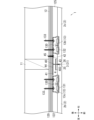
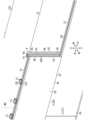
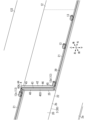
- the wall structure 1 of this embodiment has a plurality of regions partitioned by joints 3 extending in the vertical direction and joints 3 extending in the horizontal direction, and wall materials 2 are installed in each region.
- wall materials 2 rectangular or L-shaped ones can be used when viewed from the front (when viewed from a direction perpendicular to the surface of the wall material 2).
- Wall materials 2 of various shapes other than rectangular and L-shaped ones can also be used. Note that in FIG. 1, the wall material 2 is installed with horse-lined construction, but in FIG. 11, the wall material 2 is not installed with horse-lined construction.
- the wall structure 1 has a non-cross joint portion 300.
- the non-cross joint portion 300 is a portion where the joints 3 extending in the vertical direction and the joints 3 extending in the horizontal direction do not intersect in a cross shape.
- the non-cross joint portion 300 includes at least one of a T-shaped joint portion 3T and an L-shaped joint portion 3L.
- the non-cross joint portion 300 includes a left-right joint portion 30 that extends left and right, and an up-down joint portion 31 that extends up and down.
- the left-right joint portion 30 can be formed of a part or all of the joints 3 that extend left and right and divide the above-mentioned area.
- the up-down joint portion 31 can be formed of a part or all of the joints 3 that extend up and down and divide the above-mentioned area.
- the T-shaped joint 3T is formed by connecting the upper or lower ends of the upper and lower joints 31 to approximately the center in the left-right direction of the left and right joints 30.
- the T-shape also includes an inverted T-shape (a T-shape with the top and bottom reversed) and an inverted T-shape (a T-shape lying on its side).
- the L-shaped joint 3L is formed by connecting the upper or lower ends of the upper and lower joints 31 to the left or right ends of the left and right joints 30.
- the L-shape also includes an inverted L-shape (a L-shape with the top and bottom reversed) and an inverted L-shape (a L-shape lying on its side).
- the upper and lower joints 31 are formed between a pair of wall materials 2 adjacent to the left and right.
- the joint material 4 as described above is provided between the pair of wall materials 2 adjacent to the left and right.
- the joint material 4 extends to the upper ends of the pair of wall materials 2 that form the upper and lower joints 31 (see FIG. 9).
- the joint material 4 also extends to the upper end of the wall material 2 located below the upper and lower joints 31 (see FIG. 8).
- the joint material 4 extends to the upper ends of both wall materials 2. If the upper end of one of the pair of wall materials 2 adjacent to the left and right is lower than the upper end of the other wall material 2, the joint material 4 extends to the upper end of one wall material 2 (the lower upper end).
- the upper and lower joint sections 31 are provided with a receiving portion 21 provided at the upper end of the lower wall material 2 and a pressing portion 22 provided at the lower end of the upper wall material 2.
- the joint material 4 arranged in the upper and lower joint sections 31 is located in a gap 5 formed between the receiving portion 21 and the pressing portion 22.
- the gap 5 formed between the receiving portion 21 and the pressing portion 22 extends in the left-right direction and opens at the side end (left-right end) of the wall material 2. In other words, the gap 5 is continuous with the upper and lower joint sections 31.
- the upper portion 48 of the joint insertion portion 40 of the joint material 4 arranged in the upper and lower joint sections 31 is positioned to the side of the opening of the gap 5 (see FIG. 7).
- the wall material 2 is fixed to the wall base 12 at a position corresponding to the left and right joints 30. That is, wall material fasteners 13 are provided along the left and right joints 30 included in the joints 3 extending in the left-right direction, and the wall material 2 is hooked onto these wall material fasteners 13 and fixed to the wall base 12 (see Figures 3 to 6).
- the wall material 2 is fixed to the wall base 12 with a wall material fastener 13, but this is not limited thereto, and the wall material 2 may be fixed to the wall base 12 with fasteners such as nails or screws.
- the wall structure 1 is described as being made of wood, but it may also be made of steel.
- a support member extending to the left and right is placed between the steel frames (columns) lined up on the left and right, and the wall material can be supported on this support member with wall material fasteners or fixing devices (nails, screws, etc.).
- the multiple wall materials 2 used have a fixed shape, but this is not limited to this.
- multiple types of wall materials with random dimensions may be combined for construction, in which case the design of the wall surface will be improved.
- three types of wall materials 200, 201, and 202 that have the same vertical dimensions but different horizontal dimensions can be combined for construction.
- two types of wall materials 203 and 204 that have different vertical dimensions may be combined for construction.
- the joint material 4 has a generally T-shaped cross section, but this is not limiting.
- the joint material 4 may be formed, for example, with an L-shaped cross section, as long as it is in the joint 3 and can prevent water from entering.
- the joint material 4 has a joint insertion portion 40 and either an insertion portion 41 or 42.
- the wall material fasteners 13 are provided on both the left and right sides of the joint 3, but this is not limited to the above.
- one wall material fastener 13 may span the joint 3.
- the wall structure according to this embodiment differs from the wall base 12 according to the first embodiment in the configuration of the wall base 12.
- the same configuration as in the first embodiment will be denoted by the same reference numerals and the description thereof will be omitted as appropriate.
- the configuration described in the second embodiment can be applied in appropriate combination with the configuration described in the first embodiment (including the modified example).
- the wall base 12 of this embodiment has support members 111 lined up on the left and right, and cross members 112 that connect the support members 111.
- the support members 111 can be formed, for example, from steel columns.
- the cross members 112 can be formed, for example, from flat metal plates or metal members with a hat-shaped cross section. When the cross members 112 are metal members with a hat-shaped cross section, their section modulus is larger than that of flat metal plates, improving wind pressure resistance.
- the cross members 112 are formed to extend in the left-right or front-back direction. Furthermore, multiple cross members 112 are arranged in a line in the vertical direction. Each cross member 112 is fixed to the support member 111 by fasteners such as screws or nails.
- the wall material 2 is fixed to a cross member 112 provided at a position corresponding to the left and right joint section 30.
- the cross member 112 is provided along the joint 3 extending left and right, but the cross member 112 is also located at the left and right joint section 30, which is part of the joint 3 extending left and right, and the wall material 2 is fixed to the cross member 112 via a wall material fastener 13 provided on the cross member 112.
- This drainage structure is an exterior wall of a building to which a ceramic siding panel is attached, and includes a joiner and a drainage member.
- the joiner is disposed between the panels adjacent in the left-right direction so as to extend in the vertical direction, and connects the adjacent panels to each other.
- the drainage member is disposed below the joiner.
- the joiner is disposed between the back surface of the panel and the mounting surface of the building to which the panel is attached so as to be able to allow ventilation or water to pass downward.
- the drainage member has a guide portion disposed along the extension direction of the joiner, and a drainage portion disposed at the lower end of the guide portion and opening from the guide portion toward the outdoor surface of the exterior wall.
- a wall structure is provided that can improve the waterproofing between adjacent wall materials.
- the wall structure 1 of this embodiment is constructed using a horse-lined construction.
- the horse-lined wall structure 1 is constructed by arranging multiple wall materials 2 in a staggered pattern.
- multiple wall materials 2 lined up in the left-right direction and multiple wall materials 2 lined up in the left-right direction above them are constructed with a shift of about half a degree in the left-right direction. Therefore, in the wall structure 1 of this embodiment, no straight joints are formed in the vertical direction on the wall surface.
- the wall structure 1 of this embodiment is formed by a plurality of wall materials 2 arranged vertically, horizontally, on the wall base 12, and includes left and right joints 30 extending horizontally, and upper and lower joints 31 disposed between the left and right joints 30 and extending continuously at least vertically.
- a waterproof member 44 is provided in the upper and lower joints 31.
- the waterproof member 44 includes a water-stopping material 43 that is in contact with the rear surfaces of the plurality of wall materials 2.
- the water-stopping material 43 is provided so as to surround the upper and lower joints 31 in a front view.
- the wall structure 1 of this embodiment can suppress the amount of water that penetrates into the upper and lower joints 31 by using the water-stopping material 43 that is provided to surround the upper and lower joints 31, and can suppress water from penetrating through the upper and lower joints 31 to the back surface of the wall material 2, and can also guide water downward by using the waterproofing member 44 to allow it to flow down. Therefore, it is possible to achieve both a simple wall material shape and waterproofing, and the wall structure 1 does not use a sealant.
- the joint material 4 of the waterproofing member 44 includes an insert portion 41 and a joint insertion portion 40.
- the insert portion 41 is fixed to the wall base 12 to which the wall material 2 is attached.
- the joint insertion portion 40 protrudes from the insert portion 41 into the upper and lower joint portions 31 between the end face of the side end 25 of the wall material 2b and the end face of the side end 26 of the wall material 2c.
- the water-stopping material 43 of the waterproofing member 44 is located on both sides of the joint insertion portion 40 in the left-right direction and the up-down direction, and contacts the back surface of the wall material 2. Therefore, in the wall structure 1 of this embodiment, the water-stopping material 43 can further suppress the infiltration of water into the back surface of the wall material 2, improving the waterproofing.
- the term “forward” refers to the direction from inside the building to the outside.
- the term “backward” refers to the direction from outside the building to inside.
- the term “upward” refers to the vertical upward direction, and the term “downward” refers to the vertical downward direction.
- the term “leftward” refers to the direction perpendicular to the front-to-back direction and the up-to-down direction, and refers to the direction toward the left when the wall structure 1 is viewed from the front (front view).
- the term “rightward” refers to the direction perpendicular to the front-to-back direction and the up-to-down direction, and refers to the direction toward the right when the wall structure 1 is viewed from the front.
- FIG. 13 shows a wall structure 1 according to this embodiment.
- This wall structure 1 is an exterior wall of a building.
- the wall structure 1 includes a pillar 11, a wall base 12, a wall material fastener 13, a wall material 2, a waterproof member 44, and the like.
- Figure 13 shows a wooden building that uses wooden pillars 11. Multiple pillars 11 are arranged side-by-side on a base 14.
- the wall base 12 has a generally flat front surface (outdoor side) and is provided with multiple support surface materials 120 and sheet materials 122.
- the support surface materials 120 are formed in a rectangular plate shape.
- the support surface materials 120 are formed, for example, from plywood, medium density fiberboard (MDF), gypsum board, etc.
- the support surface materials 120 are arranged in front of the columns 11 (outdoor side), and are fixed to the multiple columns 11 with fasteners such as nails.
- Sheet material 122 is provided on the front surface (outdoor side) of support surface material 120.
- Sheet material 122 is, for example, a moisture-permeable waterproof sheet and a heat-shielding sheet.
- Multiple wall material fasteners 13 are provided on the front surface (outdoor side) of the wall base 12.
- the multiple wall material fasteners 13 are arranged on the front surface of the sheet material 122 and are fixed to the support surface material 120 and the pillars 11 with fasteners such as nails.
- Multiple wall materials 2 are provided on the front side (outdoor side) of the wall base 12.
- the multiple wall materials 2 are arranged in a staggered pattern. This forms a horse-lined exterior wall.
- ceramic siding material can be used as the wall material 2.
- the wall material 2 is formed in a rectangular plate shape when viewed from the front.
- a receiving portion 21 is formed as a portion 24 at the upper end of the wall material 2, and a pressing portion 22 is formed as a portion 24 at the lower end.
- the receiving portion 21 protrudes above the plate-like portion 20 of the wall material 2, and is formed over the entire length of the wall material 2 in the left-right direction.
- the thickness (front-rear dimension) of the receiving portion 21 is formed to be approximately half the thickness (front-rear dimension) of the plate-like portion 20.
- the receiving portion 21 is located rearward of the center of the plate-shaped portion 20 in the front-to-rear direction.
- the pressing portion 22 is formed to protrude downward from the plate-shaped portion 20 of the wall material 2, and is formed over the entire length of the wall material 2 in the left-to-right direction.
- the thickness (dimension in the front-to-rear direction) of the pressing portion 22 is formed to be approximately half the thickness (dimension in the front-to-rear direction) of the plate-shaped portion 20.
- the pressing portion 22 is located forward of the center of the plate-shaped portion 20 in the front-to-rear direction.
- the surface of the plate-shaped portion 20 may be flat, or may have an uneven pattern formed thereon.
- the wall material 2 further includes a locking portion 23 (see FIG. 16B).
- the locking portion 23 protrudes below the plate-shaped portion 20 at the rear side (indoor side) of the pressing portion 22, and is formed over the entire length of the wall material 2 in the left-right direction.
- the wall material 2 is attached to the front side (outdoor side) of the wall base 12 by hooking the receiving portion 21 and the locking portion 23 onto the wall material fastener 13.
- a plurality of wall materials 2 are arranged vertically and horizontally on the wall base 12, and joints 3 are formed between adjacent wall materials 2.
- Horizontal joint portions 30 extending in the horizontal direction are formed as joints 3 between multiple wall materials 2 adjacent in the vertical direction.
- Upper and lower joint portions 31 extending in the vertical direction are formed as joints 3 between multiple wall materials 2 adjacent in the horizontal direction.
- the upper and lower joints 31 are provided between two left and right joints 30 that are adjacent in the vertical direction.
- the upper and lower joints 31 are formed to extend continuously in the vertical direction.
- the upper and lower joints 31 are formed between the end faces (right end faces) of the side ends 25 of a plurality of wall materials 2 that are aligned and facing each other in the horizontal direction and the end faces (left end faces) of the side ends 26 of the wall materials 2.
- the end faces of the side ends 25, 26 of the wall materials 2 are formed flat.
- the waterproofing member 44 includes a joint material 4 and a water-stopping material 43.
- the joint material 4 includes a pair of insertion portions 41, 42 and a joint insertion portion 40.
- One insertion portion 41 protrudes leftward from the rear end of the joint insertion portion 40 in a front view, and the other insertion portion 42 protrudes rightward from the rear end of the joint insertion portion 40 in a front view.
- Each insertion portion 41, 42 is formed in a rectangular plate shape in a front view (from the front), and is formed in a strip shape with a vertical dimension longer than a horizontal dimension.
- An auxiliary line 46 is provided on the front surface of each insertion portion 41, 42.
- the auxiliary line 46 indicates the fixing position of a screw or the like.
- the auxiliary line 46 is provided over the entire vertical length of each insertion portion 41, 42.
- the auxiliary line 46 is, for example, a marking and a V-groove.
- the joint insertion portion 40 has a base 401, a stand portion 402, and an insertion portion 403.
- the base 401 is formed as a rectangular plate in side view (viewed from the left and right direction), and is formed in a strip shape with the vertical dimension longer than the front-to-rear dimension.
- the base 401 is formed over the entire vertical length of the pair of insertion portions 41, 42.
- the base 401 also protrudes approximately vertically toward the front from the boundary between the pair of insertion portions 41, 42.
- the base 402 is formed as a rectangular plate when viewed from the front, and is formed in a strip shape with the vertical dimension longer than the horizontal dimension.
- the base 402 is formed over the entire vertical length of the base 401.
- the approximate center in the horizontal direction of the rear surface of the base 402 is connected to the front end of the base 401.
- the base 401 protrudes approximately perpendicularly from the rear surface of the base 402.
- the base 402 faces the pair of insertion portions 41, 42 and is approximately parallel to them.
- the horizontal dimension of the base 402 is formed to be smaller than the horizontal dimension of the pair of insertion portions 41, 42.
- the insertion portion 403 is formed as a substantially rectangular plate in side view (viewed from the left and right direction), with the vertical dimension longer than the front-to-rear dimension, and is formed as a substantially rectangular strip.
- the vertical dimension of the insertion portion 403 is shorter than the vertical dimension of the base portion 402, and the insertion portion 403 is provided at approximately the center of the base portion 402 in the vertical direction.
- the insertion portion 403 is also provided at approximately the center of the base portion 402 in the left-to-right direction.
- the insertion portion 403 protrudes approximately vertically from the front surface of the base portion 402.
- a corresponding portion 404 is formed at the top of the insertion portion 403.
- the corresponding portion 404 is formed with a smaller front-to-rear dimension than the other portions of the insertion portion 403 by forming a notch at the top front side of the insertion portion 403.
- the corresponding portion 404 forms the upper portion of the joint material 4 in a shape that matches the shape of the receiving portion 21 of the receiving portion 24 of the wall material 2 in a side view.
- the corresponding portion 404 is approximately the same as the shape of the receiving portion 21 in a side view, and as a result, the upper portion of the joint material 4 is formed in approximately the same shape as the periphery of the receiving portion 21 at the top of the wall material 2 in a side view.
- a cut portion 405 is provided at the bottom of the insertion portion 403 (see FIG. 15C).
- the cut portion 405 is formed by cutting out an approximately V-shape from the front end of the insertion portion 403.
- the joint material 4 is cut at the position of the cut portion 405 when shortening the vertical dimension. For example, as shown in FIG. 16A, when the joint material 4 is provided above the starter 15 on which the lower end of the wall material 2 is placed, the vertical dimension of the joint material 4 may be too long and the lower end of the joint material 4 may interfere with (contact) the starter 15. In this case, the vertical dimension can be adjusted by cutting the joint material 4 at the position of the cut portion 405.
- the joint material 4 has different shapes, it is preferable to provide a mark or sticker to distinguish between the upper and lower parts so that the joint material is not installed in the wrong direction.
- the pair of insertion portions 41, 42 and the joint insertion portion 40 formed as described above can be integrally formed from metal or plastic members.
- the water-stopping material 43 is made of an elastic material such as rubber or resin.
- the water-stopping material 43 is formed in a flat plate shape with a vertical dimension longer than its horizontal dimension.
- the water-stopping material 43 is provided over the entire front surface of the base portion 402. Therefore, the pair of insertion portions 41, 42 and the water-stopping material 43 are provided at a distance from each other in the front-rear direction.
- a slit 430 is formed in the approximate center of the water-stopping material 43 in the left-right direction.
- the slit 430 is elongated and formed to extend in the up-down direction.
- the slit 430 also penetrates the water-stopping material 43 in the front-to-rear direction.
- the insertion part 403 is inserted into the slit 430 from the rear.
- the front end of the insertion part 403 protrudes forward from the slit 430. Therefore, the water-stopping material 43 is arranged around the insertion part 403 (above, below and to the sides).
- the wall structure 1 of this embodiment is constructed as follows.
- a wall material 2 (this wall material 2 is referred to as wall material 2a to distinguish it from other wall materials 2) is attached to the front side (outdoor side) of the wall base 12.
- the wall material 2a is attached by a plurality of wall material fasteners 13 (this wall material fastener 13 is referred to as wall material fasteners 13a, 13b to distinguish it from other wall material fasteners 13).
- the interval P between the plurality of wall material fasteners 13a, 13b can be, for example, 16 inches or less.
- the wall material fastener 13b is disposed a predetermined distance S away from the connection position M1 of the plurality of wall materials 2b, 2c attached to the upper stage of the wall material 2a.
- connection position M1 corresponds to the position where the upper and lower joint portions 31 are formed.
- the predetermined distance S can be, for example, about 2 inches. In this way, the wall material fastener 13b is disposed in a position that does not overlap with one of the insertion portions 41 of the waterproofing member 44.
- the wall material fastener 13 (13a, 13b) comprises a fixed portion 130, an upper locking piece 131, and a lower locking piece 132 (see Figure 14).
- the fixed portion 130 is formed in a plate shape extending in the left-right direction.
- the upper locking piece 131 is provided so as to protrude from the fixed portion 130 to the front side (outdoor side).
- the front end of the upper locking piece 131 protrudes diagonally upward.
- the lower locking pieces 132 are formed in multiples (two pieces) lined up in the left-right direction and are provided so as to protrude from the fixed portion 130 to the front side (outdoor side), with the front end of the lower locking piece 132 protruding downward.
- the wall material fasteners 13a and 13b are positioned on the front side (outdoor side) of the wall base 12.
- the front side of the wall base 12 is the front side (outdoor side) of the sheet material 122.
- the wall material 2a is positioned on the front side (outdoor side) of the wall base 12.
- another wall material 2 (this wall material 2 is referred to as wall material 2b to distinguish it from the other wall materials 2) is attached to the front side of the wall base 12.
- the wall material 2b is attached by a plurality of wall material fasteners 13.
- the end face of one side end 25 (right side) of the wall material 2b in the left-right direction is arranged substantially along the connection position M1.
- the wall material 2b is arranged in the upper tier of the wall material 2a.
- the pressing part 22 of the upper tier wall material 2b is arranged in front of (on the outdoor side of) the receiving part 21 of the lower tier wall material 2a.
- the pressing part 22 of the upper tier wall material 2b and the receiving part 21 of the lower tier wall material 2a are arranged opposite each other in the front-rear direction.
- the locking part 23 of the upper tier wall material 2b is hooked onto the upper locking piece 131 of the wall material fastener 13 that holds the lower tier wall material 2a.
- a waterproofing material 29 made of a hot melt material or the like is provided on at least one of the front surface of the receiving part 21 and the rear surface of the pressing part 22.
- the waterproofing material 29 contacts the rear surface of the pressing part 22, which faces the front surface of the receiving part 21. This improves the waterproofing between the receiving part 21 and the pressing part 22.
- Left and right joints 30 are formed between the wall materials 2a and 2b that are adjacent in the vertical direction.
- the multiple wall material fasteners 13 are arranged in front of the wall base 12 by fixing the fixing parts 130 to the wall base 12 and the pillars 11 with fasteners 133 such as screws or nails, as described above.
- the wall material 2b is arranged in front (outdoor) of the wall base 12 by hooking the lower retaining pieces 132 of the wall material fasteners 13 onto the receiving parts 21 of the wall material 2b.
- the distance between the wall material fastener 13 closest to the right end of the wall material 2b and the connection position M1 can be the same as the interval P.
- the distance between the connection position M2 and the wall material fastener 13 can be the same as the specified dimension S.
- the end of another wall material arranged above the wall material 2b is located at the connection position M2.
- the waterproofing member 44 is positioned as shown in FIG. 19.
- the insertion portion 403 of the joint material 4 of the waterproofing member 44 is positioned approximately along the connection position M1.
- the portion of the joint material 4 to the left of the joint insertion portion 40 in a front view is positioned between the wall material 2b and the wall base 12.
- the portion of the joint material 4 to the left of the joint insertion portion 40 is inserted from above between the wall material 2b and the wall base 12.
- the right end portion of the wall material 2b is pulled slightly forward to widen the gap between the rear surface of the wall material 2b and the front surface of the wall base 12.
- the waterproofing member 44 is inserted until the bottom end of the joint insertion portion 40 of the joint material 4 reaches the top end surface of the receiving portion 21 of the lower wall material 2a.
- the insertion portion 42 is fixed to the wall base 12 in the portion to the right of the joint insertion portion 40 when viewed from the front.
- a fastener 45 such as a screw or nail is driven from the front of the insertion portion 42 into the wall base 12. At this time, the fastener 45 is driven into multiple locations on the auxiliary line 46.
- the portion of the joint material 4 to the left of the joint insertion portion 40 is located between the right end of the wall material 2b and the wall base 12.
- the front surface of the water-stopping material 43 contacts the rear surface (back surface) of the wall material 2b.
- the side surface (left surface) of the insertion portion 403 is in contact with or adjacent to the end surface (right end surface) of the side end portion 25 of the wall material 2b.
- the upper portion of the insertion portion 403 has a side shape that is almost the same as the upper portion of the wall material 2b, so there is less space between the end surface of the side end portion 25 and the insertion portion 403 that leads to the rear surface of the wall material 2b, making it difficult for water such as rainwater to flow around to the rear surface side of the wall material 2b, improving the waterproofing of the wall structure 1.
- the water-stopping material 43 is formed longer in the vertical direction than the insertion portion 403, the upper and lower portions of the water-stopping material 43 can easily reach and contact the rear surfaces of the connecting portions of the vertically adjacent wall materials 2, improving waterproofing.
- a new wall material fastener 13 is provided on the left side of the upper part of the joint material 4 of the waterproofing member 44 when viewed from the front.
- This wall material fastener 13 is referred to as wall material fastener 13c to distinguish it from the other wall material fasteners 13.
- the wall material fastener 13c is placed on the front side of the wall base 12 by fixing the fixing part 130 to the wall base 12 of the supporting surface material 120 or the pillar 11 with fixings 133 such as screws or nails. Also, by hooking the lower retaining piece 132 of the wall material fastener 13c onto the receiving part 21 of the wall material 2b, the right end part of the wall material 2b is fixed to the front side (outdoor side) of the wall base 12.
- a new wall material fastener 13 is provided on the right side of the lower part of the joint material 4 of the waterproofing member 44 when viewed from the front.
- This wall material fastener 13 is referred to as wall material fastener 13d to distinguish it from the other wall material fasteners 13.
- the wall material fastener 13d is placed on the front side of the wall base 12 by fixing the fixing part 130 to the wall base 12 of the supporting surface material 120 or the pillar 11 with fixings 133 such as screws or nails.
- the wall material 2a is fixed to the front side (outdoor side) of the wall base 12 by hooking the lower retaining piece 132 of the wall material fastener 13d onto the receiving part 21 of the lower wall material 2a.
- multiple new wall material fasteners 13 are provided to the right of wall material fastener 13d when viewed from the front.
- these wall material fasteners 13 are positioned on the front side (outdoor side) of the wall base 12 by fixing the fixing parts 130 to the supporting surface material 120 or the wall base 12 of the pillar 11 with fixing devices 133 such as screws or nails.
- the wall material 2a is fixed to the front side (outdoor side) of the wall base 12 by hooking the lower retaining pieces 132 of these wall material fasteners 13 onto the receiving parts 21 of the lower wall material 2a.
- another wall material 2 (called wall material 2c to distinguish this wall material 2 from the other wall materials 2) is attached to the right side of wall material 2b, on the front side (outdoor side) of the wall base 12.
- Wall material 2c is attached in the same manner as wall material 2b. That is, wall material 2c is placed on the upper level of wall material 2a.
- the pressing part 22 of the upper level wall material 2c is placed on the front side (outdoor side) of the receiving part 21 of the lower level wall material 2a. Therefore, the pressing part 22 of the upper level wall material 2c and the receiving part 21 of the lower level wall material 2a are placed opposite each other.
- the locking part 23 of the upper level wall material 2c is hooked onto the wall material fastener 13 that holds the lower level wall material 2a.
- Another wall material fastener 13d is provided on the receiving part 21 of the upper level wall material 2c, and the wall material fastener 13 is fixed to the wall base 12 with a fixing device 133.
- upper and lower joints 31 are formed. That is, the end face of the right side end 25 of wall material 2b and the end face of the left side end 26 of wall material 2c are arranged opposite each other in the left-right direction to form upper and lower joints 31.
- a waterproof member 44 is also provided in upper and lower joints 31. That is, the insertion portion 403 of the joint insertion portion 40 of joint material 4 is arranged in the upper and lower joints 31 between the end face of the right side end 25 of wall material 2b and the end face of the left side end 26 of wall material 2c.
- the end face of the right side end 25 of the wall material 2b and the end face of the left side end 26 of the wall material 2c are in contact with or close to the left and right side faces of the insertion part 403, respectively, and a gap of the thickness of the insertion part 403 (dimension in the left-right direction) is formed as the upper and lower joint parts 31.
- the rear surface (back surface) of the right side end 26 of the left wall material 2b is in contact with the front surface of the water stop material 43 on the left side of the insertion part 403, and the rear surface (back surface) of the left side end 26 of the right wall material 2c is in contact with the front surface of the water stop material 43 on the right side of the insertion part 403.
- the wall base 12 and the multiple wall materials 2 are arranged separately in the front-rear direction.
- a space is provided between the front surface of the wall base 12 and the rear surfaces of the multiple wall materials 2, and this space is formed as the ventilation layer 125.
- the upper end of the insertion portion 403 of the joint insertion portion 40 of the waterproofing member 44 extends to the upper end of the receiving portion 21 of the upper wall material 2b, 2c. That is, the upper end of the insertion portion 403 of the joint insertion portion 40 of the waterproofing member 44 and the upper end of the receiving portion 21 of the upper wall material 2b, 2c are at the same height, or the upper end of the insertion portion 403 of the joint insertion portion 40 of the waterproofing member 44 protrudes slightly above the upper end of the receiving portion 21 of the upper wall material 2b, 2c to the extent that it does not interfere with the wall material above the upper wall material 2b, 2c. Also, the lower end of the insertion portion 403 of the joint insertion portion 40 of the waterproofing member 44 is in contact with or close to the upper end of the receiving portion 21 of the lower wall material 2a.
- the water-stopping material 43 is formed longer in the vertical direction than the insertion portion 403 of the joint insertion portion 40, so that the upper portion of the water-stopping material 43 reaches and contacts the rear surface of each wall material 2 of the T-shaped connection portion formed by the upper wall material 2b, 2c and the wall material of the further upper portion, and the lower portion of the water-stopping material 43 reaches and contacts the rear surface of each wall material 2 of the inverted T-shaped connection portion formed by the lower wall material 2a and the upper wall material 2b, 2c.
- the water-stopping material 43 of the waterproofing member 44 is provided from the rear surface of the upper and lower joint portion formed by the wall materials 2b, 2c adjacent in the left and right direction to the rear surface between the receiving portions 21 of the wall materials 2b, 2c, and even to the rear surface of the lower end portion of the upper wall material, which not only prevents water such as rainwater from entering through the upper and lower joint portions 31, but also prevents water such as rainwater from entering between the receiving portions 21.
- the water-stopping material 43 of the waterproofing member 44 is provided from the rear surface of the upper and lower joint portion 31 formed by the wall materials 2b and 2c adjacent in the left-right direction to the rear surface of the upper end portion of the wall material 2a, so that water running sideways through the gap between the receiving portion 21 at the upper end of the lower wall material 2a and the holding portion 22 at the lower end of the wall materials 2b and 2c in the upper layer can be prevented from entering through the joint 3.
- the water-stopping material 43 is provided so as to surround the upper and lower joints 31 when viewed from the front (when viewed from a direction perpendicular to the surface of the wall material 2). Therefore, water that has infiltrated into the upper and lower joints 31 is less likely to flow around the periphery of the upper and lower joints 31 to the back surface of the wall material 2, improving waterproofing.
- the wall structure 1A according to this embodiment differs from the wall structure 1 according to the third embodiment in the configuration of the wall material fastener 13.
- the same configuration as in the third embodiment will be denoted by the same reference numerals and the description thereof will be omitted as appropriate.
- the configuration described in the fourth embodiment can be applied in appropriate combination with the configuration described in the third embodiment.
- the wall material 2a is placed on the front side (outdoor side) of the wall base 12, and then, as shown in FIG. 24, the wall material 2a is fixed to the wall base 12 using a long fastener 16.
- the long fastener 16 is formed to be long in the left-right direction, and the left-right dimension of the long fastener 16 is formed to be larger than the left-right dimension of the wall material fastener 13 of embodiment 1.
- the long fastener 16 can have a length approximately twice the interval P shown in FIG. 17.
- the long fastener 16 comprises a fixed portion 160, a number of upper locking pieces 161, and a number of lower locking pieces 162 (see FIG. 24).
- the fixed portion 160 is formed in a plate shape extending in the left-right direction.
- the upper locking pieces 161 are formed side by side in the left-right direction and are provided so as to protrude from the fixed portion 160 to the front side (outdoor side).
- the front ends of the upper locking pieces 161 protrude diagonally upward.
- the lower locking pieces 162 are formed side by side in the left-right direction and are provided so as to protrude from the fixed portion 160 to the front side (outdoor side).
- the front ends of the lower locking pieces 162 protrude downward.
- the long fastener 16 is positioned on the front side (outdoor side) of the wall base 12. Also, by hooking the lower locking piece 162 of the long fastener 16 onto the receiving portion 21 of the wall material 2a, the wall material 2a is positioned on the front side (outdoor side) of the wall base 12.
- wall material 2b is attached to the front side (outdoor side) of the wall base 12.
- Wall material 2b is attached with long fasteners 16.
- Wall material 2b is placed on the upper level of wall material 2a in the same manner as in embodiment 3, except that it is attached with long fasteners 16.
- the waterproofing member 44 is placed. As in the first embodiment, the waterproofing member 44 is placed between the wall material 2b and the wall base 12 with the left side of the joint insertion portion 40 in front view. Also, as shown by the arrow A1 in FIG. 26, the waterproofing member 44 is inserted from above between the wall material 2b and the wall base 12 with the left side of the joint insertion portion 40. At this time, as shown by the arrow A2 in FIG. 26, the right end portion of the wall material 2b is pulled slightly forward to widen the gap between the rear surface of the wall material 2b and the front surface of the wall base 12.
- the waterproofing member 44 is inserted until the lower end surface of the joint material 4 reaches the upper end surface of the receiving portion 21 of the lower wall material 2a. Note that, in order to be able to pull the right end portion of the wall material 2b slightly forward as shown by the arrow A2, it is desirable to fix the right side of the long fastener 16 with a fixing device after the waterproofing member 44 is inserted.
- the insertion portion 42 is fixed to the wall base 12 in the portion to the right of the joint insertion portion 40 when viewed from the front.
- the portion of the joint material 4 to the left of the joint insertion portion 40 is located between the right end of the wall material 2b and the wall base 12.
- the front surface of the water-stopping material 43 comes into contact with the rear surface of the wall material 2b.
- the side surface (left surface) of the insertion portion 403 is in contact with or adjacent to the end face (right end face) of the side end portion 25 of the wall material 2b.
- the upper portion of the insertion portion 403 has substantially the same side shape as the upper portion of the wall material 2b, there is less space between the end face of the side end portion 25 and the insertion portion 403 that leads to the rear surface of the wall material 2b, making it difficult for water such as rainwater to flow around to the rear surface side of the wall material 2b, improving the waterproofing of the wall structure 1.
- the water-stopping material 43 is formed longer in the vertical direction than the insertion portion 403, the upper and lower portions of the water-stopping material 43 can easily reach and come into contact with the rear of the connection portion of the vertically adjacent wall materials 2, improving waterproofing.
- a new long fastener 16 is provided on the right side of the waterproofing member 44.
- This long fastener 16 like the other long fasteners 16, is placed on the front side (outdoor side) of the wall base 12 by fixing the fixing part 160 to the supporting surface material 120 or the wall base 12 of the column 11 with fixing tools such as screws or nails.
- the wall material 2a is fixed to the front side (outdoor side) of the wall base 12 by hooking the lower locking piece 162 of the long fastener 16 to the receiving part 21 of the lower wall material 2a.
- another wall material 2c is attached to the front side (outdoor side) of the wall base 12 as in embodiment 1.
- the upper part of the wall material 2c is fixed to the wall base 12 by another long fastener 16 in the same manner as described above.
- the upper and lower joints 31 are formed as shown in FIG. 14, as in the third embodiment.
- the upper and lower joints 31 are also inserted into the joint inserts 40 of the joint material 4.
- the front surface of the water-stopping material 43 contacts the rear surfaces (rear surfaces) of the wall materials 2b and 2c on both the left and right sides of the joint inserts 40.
- the water-stopping material 43 is formed to be longer in the vertical direction than the inserts 403 of the joint inserts 40, so that the upper part of the water-stopping material 43 reaches and contacts the rear surfaces of the wall materials 2 in the T-shaped connection formed by the upper wall materials 2b and 2c and the wall materials in the further upper part, and the lower part of the water-stopping material 43 reaches and contacts the rear surfaces of the wall materials 2 in the inverted T-shaped connection formed by the lower wall material 2a and the upper wall materials 2b and 2c.
- the water-stopping material 43 of the waterproofing member 44 is provided from the rear surface of the upper and lower joints formed by the wall materials 2b, 2c adjacent in the left-right direction to the rear surface between the receiving portions 21 of the wall materials 2b, 2c, and even to the rear surface of the lower end of the upper wall material. This not only prevents rainwater and other water from entering through the upper and lower joints 31, but also prevents rainwater and other water from entering between the receiving portions 21.
- the water-stopping material 43 of the waterproofing member 44 is provided from the rear surface of the upper and lower joint portion 31 formed by the wall materials 2b and 2c adjacent in the left-right direction to the rear surface of the upper end portion of the wall material 2a, so that water running sideways through the gap between the receiving portion 21 at the upper end of the lower wall material 2a and the holding portion 22 at the lower end of the wall materials 2b and 2c in the upper layer can be prevented from infiltrating through the joint 3.
- the wall structure 1B according to this embodiment differs from the wall structures 1 and 1A according to the third or fourth embodiment in the configuration of the pillar 11 and the configuration of the wall base 12.
- the same configurations as those in the third or fourth embodiment will be denoted by the same reference numerals and will not be described as appropriate.
- the configuration described in the fifth embodiment can be applied in appropriate combination with the configuration described in the third or fourth embodiment.
- the pillars 11 are made of wood, and the wall structure 1 is made of wood, but in the fifth embodiment, the pillars 11 are made of metal, such as steel, and the wall structure 1B is made of steel.
- the wall material fasteners 13 and joint material 4 were attached to the supporting surface material 120 of the wall base 12 or to the pillars 11, but in this embodiment, the wall base 12 further includes a furring strip 17, and the wall material fasteners 13 and waterproofing members 44 are attached to the furring strips 17 (see Figures 29, 30, and 31).
- the furring strips 17 are horizontal furring strips that extend in the left-right direction and are formed of metal such as steel plate.
- the furring strips 17 have a furring strip body 170 that has a generally U-shaped cross section that opens toward the rear, and attachment pieces 171 provided at the upper and lower ends of the furring strip body 170.
- the upper attachment piece 171 protrudes upward from the upper end of the furring strip body 170.
- the lower attachment piece 171 protrudes downward from the lower end of the furring strip body 170.
- the furring strips 17 are positioned on the front side (outdoor side) of the supporting surface material 120 and the sheet material 122 by fixing the attachment pieces 171 to the supporting surface material 120 or the pillar 11 with fasteners 172 such as screws or nails.
- the wall material fastener 13 is then positioned in front of the furring strip 17 (outdoor side) by fixing the fixing portion 130 to the furring strip main body 170 with a fastener 133 such as a screw or nail.
- the joint material 4 is positioned in front of the furring strip 17 (outdoor side) by driving a fastener 45 such as a screw or nail from the front of the insertion portion 42 into the furring strip main body 170.
- the joint material 4 of the waterproofing member 44 is positioned to span adjacent furring strips 17 in the vertical direction.
- the furring strips 17 can form an air-permeable layer 125 between the wall material 2 and the sheet material 122.
- the wall structure 1C according to this embodiment differs from the wall structure 1B according to the fifth embodiment in the configuration of the wall base 12.
- the same configurations as those in the third to fifth embodiments will be denoted by the same reference numerals and will not be described as appropriate.
- the configuration described in the sixth embodiment can be applied in appropriate combination with the configurations described in the third to fifth embodiments.
- the wall base 12 is provided with furring strips 17, but in the sixth embodiment, the wall base 12 is provided with a reinforcing plate 18 instead of the furring strips 17.
- the wall material fasteners 13 and the waterproofing members 44 are attached to the furring strips 17, but in this embodiment, the wall material fasteners 13 and the waterproofing members 44 are attached to the pillars 11 and the supporting surface members 120 via the reinforcing plate 18, as shown in Figs. 32, 33, and 34.
- the reinforcing plate 18 is a flat plate material that is rectangular in front view and extends in the left-right direction.
- the reinforcing plate 18 is made of metal such as a steel plate.
- the reinforcing plate 18 is fixed to the wall base 12 and the pillars 11 by fasteners 181 such as screws or nails.
- the wall material fastener 13 is then placed on the front side (outdoor side) of the reinforcing plate 18 by fixing the fixing portion 130 to the column 11 and the supporting surface material 120 with fasteners 133 such as screws or nails with the fixing portion 130 in contact with the front surface of the reinforcing plate 18.
- the joint material 4 is placed and fixed on the front side (outdoor side) of the reinforcing plate 18 by driving fasteners 45 such as screws or nails from the front of the insertion portion 42 into the supporting surface material 120 with the insertion portion 41 in contact with the front surface of the reinforcing plate 18.
- the joint material 4 of the waterproofing member 44 is placed across adjacent reinforcing plates 18 in the vertical direction.
- the reinforcing plate 18 can improve the mounting strength of the wall material fastener 13 and the waterproofing member 44.
- the wall structure 1D according to this embodiment differs from the wall structure 1B according to the fifth embodiment in the configuration of the wall base 12.
- the same configurations as those in the third to sixth embodiments will be denoted by the same reference numerals and will not be described as appropriate.
- the configuration described in the seventh embodiment can be applied in appropriate combination with the configurations described in the third to sixth embodiments.
- the wall base 12 of the fifth embodiment further includes a heat insulating material 19.
- the heat insulating material 19 is formed into a plate shape from foamed plastic, rock wool, or the like.
- the heat insulating material 19 is provided between the support surface material 120 and the sheet material 122.
- the heat insulating material 19 is formed to have higher heat insulating performance than the support surface material 120.
- the furring strips 17 are disposed in front of the sheet material 122, and are fixed to the support surface material 120 and the pillar 11 with long screws 175.
- the insulating material 19 allows the wall structure 1D to be formed with high insulating performance.
- the waterproof member 44 may be, for example, as shown in Fig. 38, a water-stopping material 43 having no insertion portion 403 and no slit 430 formed therein, attached to a base portion 402.
- the joint material 4 has insertion portions 41 and 42, a base portion 401, and a base portion 402.
- the waterproof member 44 is not limited to these forms.
- the wall structure 1 is a wall structure in which the wall material 2 is constructed in an area partitioned by joints 3 extending vertically and horizontally, and the joints 3 have non-cross joint portions 300 including at least one of a T-shaped joint portion 3T and an L-shaped joint portion 3L.
- the non-cross joint portion 300 includes a horizontal joint portion 30 extending horizontally and an upper-lower joint portion 31 extending vertically.
- the upper-lower joint portion 31 is formed between a pair of wall materials 2 adjacent to each other horizontally, and a joint material 4 is provided therein.
- the joint material 4 by inserting the joint material 4 into the joint 3, the amount of water that seeps in is reduced, preventing water from adhering to the back surface of the wall material 2, while guiding the water downward and allowing it to flow down, resulting in a wall structure that does not require the use of a sealant.
- the second aspect is the wall structure 1 according to the first aspect, in which the joint material 4 extends to the upper ends of the pair of wall materials 2 that form the upper and lower joint portions 31, and also extends to the upper end of the wall material 2 located below the upper and lower joint portions 31.
- the joint material 4 is provided between the left and right receiving parts 21, so water can be prevented from entering between the receiving parts 21.
- water running sideways through the gap between the receiving part 21 at the upper end of the lower wall material 2 and the pressing part 22 at the lower end of the wall material 2 above it can be prevented from entering through the joint.
- the third aspect is a wall structure 1 according to the first or second aspect, in which the upper and lower joints 31 are provided with a receiving part 21 provided at the upper end of the lower wall material 2 and a pressing part 22 provided at the lower end of the upper wall material 2 and facing the receiving part 21.
- the joint material 4 is located in the gap 5 formed between the receiving part 21 and the pressing part 22.
- the joint material 4 receives and allows water that enters the gap 5 between the receiving portion 21 and the pressing portion 22 and runs sideways to flow downward, thereby preventing water from penetrating to the back side of the wall material 2.
- the fourth aspect is a wall structure 1 according to any one of the first to third aspects, further comprising a planar wall base 12.
- the wall material 2 is fixed to the wall base 12 at positions corresponding to the left and right joints 30.
- the left and right joints 30 can be easily formed along the wall material 2, making it easy to form a wall structure that does not use a sealant.
- the fifth aspect is a wall structure 1 according to any one of the first to fourth aspects, further comprising a wall base 12 having support members 111 arranged on the left and right and cross members 112 connecting the support members 111.
- the wall member 2 is fixed to the cross members 112 provided at positions corresponding to the left and right joints 30.
- the cross members 112 can increase the strength of the support members 111 and the mounting strength of the wall member 2, resulting in a highly rigid wall structure 1.
- the sixth aspect is a wall structure in which a left-right joint section 30 extending left and right and an upper-lower joint section 31 extending continuously at least up and down are formed by a plurality of wall materials 2 arranged up, down, left and right on the wall base 12, and a waterproofing member 44 is provided in the upper and lower joint sections 31.
- the waterproofing member 44 includes a water-stopping material 43 that is in contact with the back surfaces of the plurality of wall materials 2.
- the water-stopping material 43 is provided so as to surround the upper and lower joint sections 31 in a front view.
- the water-stopping material 43 contacts the back surface of the wall material 2 so as to surround the upper and lower joints 31, making it difficult for rainwater or other water that has infiltrated the upper and lower joints 31 to find its way around to the back surface of the wall material 2, improving the waterproofing between adjacent wall materials 2.
- the seventh aspect is the sixth aspect, in which the waterproofing member 44 further includes a joint material 4.
- the joint material 4 includes insertion portions 41, 42 that are fixed to the wall base 12, and joint insertion portions 40 that protrude from the insertion portions 41, 42 and are inserted into the upper and lower joint portions 31 from the back side of the multiple wall materials 2.
- the water-stopping material 43 is provided around the joint insertion portions 40.
- the water-stopping material 43 provided around the joint insertion portion 40 inserted into the upper and lower joint portions 31 can be easily installed to surround the upper and lower joint portions 31 when viewed from the front, making it easy to form a wall structure 1 that makes it difficult for water such as rainwater to find its way around the back side of the multiple wall materials 2.
- the eighth aspect is the sixth or seventh aspect, in which the end faces of the multiple wall materials 2 located at the upper and lower joint portions 31 are formed flat.
- This configuration reduces the likelihood of gaps occurring between the joint insertion portion 40 and the end face, improving waterproofing.
- the ninth aspect is any one of the sixth to eighth aspects, in which a space is formed between the wall base 12 and the multiple wall materials 2.
- the insertion portions 41, 42 are separated from the water-stopping material 43.
Landscapes
- Engineering & Computer Science (AREA)
- Architecture (AREA)
- Civil Engineering (AREA)
- Structural Engineering (AREA)
- Finishing Walls (AREA)
Priority Applications (1)
| Application Number | Priority Date | Filing Date | Title |
|---|---|---|---|
| JP2025524156A JPWO2024248072A1 (https=) | 2023-05-30 | 2024-05-30 |
Applications Claiming Priority (4)
| Application Number | Priority Date | Filing Date | Title |
|---|---|---|---|
| JP2023-089020 | 2023-05-30 | ||
| JP2023089020 | 2023-05-30 | ||
| JP2024-045299 | 2024-03-21 | ||
| JP2024045299 | 2024-03-21 |
Publications (1)
| Publication Number | Publication Date |
|---|---|
| WO2024248072A1 true WO2024248072A1 (ja) | 2024-12-05 |
Family
ID=93658050
Family Applications (1)
| Application Number | Title | Priority Date | Filing Date |
|---|---|---|---|
| PCT/JP2024/019818 Ceased WO2024248072A1 (ja) | 2023-05-30 | 2024-05-30 | 壁構造 |
Country Status (2)
| Country | Link |
|---|---|
| JP (1) | JPWO2024248072A1 (https=) |
| WO (1) | WO2024248072A1 (https=) |
Citations (4)
| Publication number | Priority date | Publication date | Assignee | Title |
|---|---|---|---|---|
| JPS59158634U (ja) * | 1983-04-08 | 1984-10-24 | 日本軽金属株式会社 | 壁仕上げ構造 |
| JPS63251566A (ja) * | 1987-04-09 | 1988-10-19 | 株式会社 チユ−オ− | サイデイングの目地ジヨイナ− |
| US20120227341A1 (en) * | 2009-11-26 | 2012-09-13 | 2175190 Ontario Inc. | Devices for Anchoring Stone Facing Elements Comprising Retaining Members Pressing Against the Wall |
| JP2018119379A (ja) * | 2017-01-27 | 2018-08-02 | トヨタホーム株式会社 | 外壁目地構造 |
-
2024
- 2024-05-30 JP JP2025524156A patent/JPWO2024248072A1/ja active Pending
- 2024-05-30 WO PCT/JP2024/019818 patent/WO2024248072A1/ja not_active Ceased
Patent Citations (4)
| Publication number | Priority date | Publication date | Assignee | Title |
|---|---|---|---|---|
| JPS59158634U (ja) * | 1983-04-08 | 1984-10-24 | 日本軽金属株式会社 | 壁仕上げ構造 |
| JPS63251566A (ja) * | 1987-04-09 | 1988-10-19 | 株式会社 チユ−オ− | サイデイングの目地ジヨイナ− |
| US20120227341A1 (en) * | 2009-11-26 | 2012-09-13 | 2175190 Ontario Inc. | Devices for Anchoring Stone Facing Elements Comprising Retaining Members Pressing Against the Wall |
| JP2018119379A (ja) * | 2017-01-27 | 2018-08-02 | トヨタホーム株式会社 | 外壁目地構造 |
Also Published As
| Publication number | Publication date |
|---|---|
| JPWO2024248072A1 (https=) | 2024-12-05 |
Similar Documents
| Publication | Publication Date | Title |
|---|---|---|
| CA2544713C (en) | Wall materials bracket and insulating wall structure | |
| JP6283335B2 (ja) | 外装構造 | |
| JP2009084896A (ja) | 外壁施工構造 | |
| WO2024248072A1 (ja) | 壁構造 | |
| KR100901005B1 (ko) | 건축 외장재 위치조정 및 조립장치 | |
| JPH1193195A (ja) | 地下壁用打込式コンクリート型枠 | |
| JP3709276B2 (ja) | 壁体構造物 | |
| JP4159091B2 (ja) | 間仕切壁構造 | |
| JP2761410B2 (ja) | 壁耐火目地構造 | |
| KR101783849B1 (ko) | 공동주택용 차음벽 | |
| CN211774834U (zh) | 一种隔热型隔断墙 | |
| JP2020139404A (ja) | 耐火構造 | |
| JP2001073531A (ja) | タイル貼付パネルの取付構造 | |
| JP3822784B2 (ja) | 石材パネルの取付構造 | |
| JP2025062482A (ja) | 目地構造 | |
| JP7808360B1 (ja) | 取付具、盛土構造及び盛土構造の施工方法 | |
| JP3507817B2 (ja) | 壁パネルの接続構造 | |
| KR101949393B1 (ko) | 서포트 일체형 빔 구조 지하 차수벽 | |
| JP2798994B2 (ja) | パネルの目地構造 | |
| JP2016084664A (ja) | 耐火構造 | |
| JP7329280B1 (ja) | パネル及びパネルの施工方法 | |
| JPH0347358A (ja) | パネルの目地構造 | |
| JP7629296B2 (ja) | 耐火目地構造及び耐火目地構造の施工方法 | |
| KR102959790B1 (ko) | 마감패널 고정 어셈블리 | |
| JP2025062483A (ja) | 取付具 |
Legal Events
| Date | Code | Title | Description |
|---|---|---|---|
| 121 | Ep: the epo has been informed by wipo that ep was designated in this application |
Ref document number: 24815553 Country of ref document: EP Kind code of ref document: A1 |
|
| ENP | Entry into the national phase |
Ref document number: 2025524156 Country of ref document: JP Kind code of ref document: A |
|
| WWE | Wipo information: entry into national phase |
Ref document number: 2025524156 Country of ref document: JP |
|
| NENP | Non-entry into the national phase |
Ref country code: DE |