WO2024247656A1 - 積層体 - Google Patents
積層体 Download PDFInfo
- Publication number
- WO2024247656A1 WO2024247656A1 PCT/JP2024/017383 JP2024017383W WO2024247656A1 WO 2024247656 A1 WO2024247656 A1 WO 2024247656A1 JP 2024017383 W JP2024017383 W JP 2024017383W WO 2024247656 A1 WO2024247656 A1 WO 2024247656A1
- Authority
- WO
- WIPO (PCT)
- Prior art keywords
- group
- carbon atoms
- layer
- formula
- laminate
- Prior art date
- Legal status (The legal status is an assumption and is not a legal conclusion. Google has not performed a legal analysis and makes no representation as to the accuracy of the status listed.)
- Ceased
Links
Images



Classifications
-
- B—PERFORMING OPERATIONS; TRANSPORTING
- B32—LAYERED PRODUCTS
- B32B—LAYERED PRODUCTS, i.e. PRODUCTS BUILT-UP OF STRATA OF FLAT OR NON-FLAT, e.g. CELLULAR OR HONEYCOMB, FORM
- B32B15/00—Layered products comprising a layer of metal
- B32B15/04—Layered products comprising a layer of metal comprising metal as the main or only constituent of a layer, which is next to another layer of the same or of a different material
- B32B15/08—Layered products comprising a layer of metal comprising metal as the main or only constituent of a layer, which is next to another layer of the same or of a different material of synthetic resin
-
- B—PERFORMING OPERATIONS; TRANSPORTING
- B32—LAYERED PRODUCTS
- B32B—LAYERED PRODUCTS, i.e. PRODUCTS BUILT-UP OF STRATA OF FLAT OR NON-FLAT, e.g. CELLULAR OR HONEYCOMB, FORM
- B32B15/00—Layered products comprising a layer of metal
- B32B15/20—Layered products comprising a layer of metal comprising aluminium or copper
-
- B—PERFORMING OPERATIONS; TRANSPORTING
- B32—LAYERED PRODUCTS
- B32B—LAYERED PRODUCTS, i.e. PRODUCTS BUILT-UP OF STRATA OF FLAT OR NON-FLAT, e.g. CELLULAR OR HONEYCOMB, FORM
- B32B37/00—Methods or apparatus for laminating, e.g. by curing or by ultrasonic bonding
- B32B37/02—Methods or apparatus for laminating, e.g. by curing or by ultrasonic bonding characterised by a sequence of laminating steps, e.g. by adding new layers at consecutive laminating stations
- B32B37/025—Transfer laminating
-
- B—PERFORMING OPERATIONS; TRANSPORTING
- B32—LAYERED PRODUCTS
- B32B—LAYERED PRODUCTS, i.e. PRODUCTS BUILT-UP OF STRATA OF FLAT OR NON-FLAT, e.g. CELLULAR OR HONEYCOMB, FORM
- B32B7/00—Layered products characterised by the relation between layers; Layered products characterised by the relative orientation of features between layers, or by the relative values of a measurable parameter between layers, i.e. products comprising layers having different physical, chemical or physicochemical properties; Layered products characterised by the interconnection of layers
- B32B7/04—Interconnection of layers
- B32B7/06—Interconnection of layers permitting easy separation
-
- B—PERFORMING OPERATIONS; TRANSPORTING
- B32—LAYERED PRODUCTS
- B32B—LAYERED PRODUCTS, i.e. PRODUCTS BUILT-UP OF STRATA OF FLAT OR NON-FLAT, e.g. CELLULAR OR HONEYCOMB, FORM
- B32B7/00—Layered products characterised by the relation between layers; Layered products characterised by the relative orientation of features between layers, or by the relative values of a measurable parameter between layers, i.e. products comprising layers having different physical, chemical or physicochemical properties; Layered products characterised by the interconnection of layers
- B32B7/04—Interconnection of layers
- B32B7/12—Interconnection of layers using interposed adhesives or interposed materials with bonding properties
-
- C—CHEMISTRY; METALLURGY
- C08—ORGANIC MACROMOLECULAR COMPOUNDS; THEIR PREPARATION OR CHEMICAL WORKING-UP; COMPOSITIONS BASED THEREON
- C08F—MACROMOLECULAR COMPOUNDS OBTAINED BY REACTIONS ONLY INVOLVING CARBON-TO-CARBON UNSATURATED BONDS
- C08F20/00—Homopolymers and copolymers of compounds having one or more unsaturated aliphatic radicals, each having only one carbon-to-carbon double bond, and only one being terminated by only one carboxyl radical or a salt, anhydride, ester, amide, imide or nitrile thereof
- C08F20/02—Monocarboxylic acids having less than ten carbon atoms, Derivatives thereof
- C08F20/10—Esters
- C08F20/22—Esters containing halogen
-
- C—CHEMISTRY; METALLURGY
- C08—ORGANIC MACROMOLECULAR COMPOUNDS; THEIR PREPARATION OR CHEMICAL WORKING-UP; COMPOSITIONS BASED THEREON
- C08G—MACROMOLECULAR COMPOUNDS OBTAINED OTHERWISE THAN BY REACTIONS ONLY INVOLVING UNSATURATED CARBON-TO-CARBON BONDS
- C08G18/00—Polymeric products of isocyanates or isothiocyanates
- C08G18/06—Polymeric products of isocyanates or isothiocyanates with compounds having active hydrogen
- C08G18/70—Polymeric products of isocyanates or isothiocyanates with compounds having active hydrogen characterised by the isocyanates or isothiocyanates used
- C08G18/72—Polyisocyanates or polyisothiocyanates
- C08G18/77—Polyisocyanates or polyisothiocyanates having heteroatoms in addition to the isocyanate or isothiocyanate nitrogen and oxygen or sulfur
- C08G18/78—Nitrogen
- C08G18/79—Nitrogen characterised by the polyisocyanates used, these having groups formed by oligomerisation of isocyanates or isothiocyanates
-
- C—CHEMISTRY; METALLURGY
- C08—ORGANIC MACROMOLECULAR COMPOUNDS; THEIR PREPARATION OR CHEMICAL WORKING-UP; COMPOSITIONS BASED THEREON
- C08L—COMPOSITIONS OF MACROMOLECULAR COMPOUNDS
- C08L33/00—Compositions of homopolymers or copolymers of compounds having one or more unsaturated aliphatic radicals, each having only one carbon-to-carbon double bond, and only one being terminated by only one carboxyl radical, or of salts, anhydrides, esters, amides, imides or nitriles thereof; Compositions of derivatives of such polymers
- C08L33/04—Homopolymers or copolymers of esters
- C08L33/14—Homopolymers or copolymers of esters of esters containing halogen, nitrogen, sulfur, or oxygen atoms in addition to the carboxy oxygen
-
- C—CHEMISTRY; METALLURGY
- C08—ORGANIC MACROMOLECULAR COMPOUNDS; THEIR PREPARATION OR CHEMICAL WORKING-UP; COMPOSITIONS BASED THEREON
- C08L—COMPOSITIONS OF MACROMOLECULAR COMPOUNDS
- C08L75/00—Compositions of polyureas or polyurethanes; Compositions of derivatives of such polymers
- C08L75/02—Polyureas
-
- C—CHEMISTRY; METALLURGY
- C23—COATING METALLIC MATERIAL; COATING MATERIAL WITH METALLIC MATERIAL; CHEMICAL SURFACE TREATMENT; DIFFUSION TREATMENT OF METALLIC MATERIAL; COATING BY VACUUM EVAPORATION, BY SPUTTERING, BY ION IMPLANTATION OR BY CHEMICAL VAPOUR DEPOSITION, IN GENERAL; INHIBITING CORROSION OF METALLIC MATERIAL OR INCRUSTATION IN GENERAL
- C23C—COATING METALLIC MATERIAL; COATING MATERIAL WITH METALLIC MATERIAL; SURFACE TREATMENT OF METALLIC MATERIAL BY DIFFUSION INTO THE SURFACE, BY CHEMICAL CONVERSION OR SUBSTITUTION; COATING BY VACUUM EVAPORATION, BY SPUTTERING, BY ION IMPLANTATION OR BY CHEMICAL VAPOUR DEPOSITION, IN GENERAL
- C23C18/00—Chemical coating by decomposition of either liquid compounds or solutions of the coating forming compounds, without leaving reaction products of surface material in the coating; Contact plating
- C23C18/16—Chemical coating by decomposition of either liquid compounds or solutions of the coating forming compounds, without leaving reaction products of surface material in the coating; Contact plating by reduction or substitution, e.g. electroless plating
- C23C18/18—Pretreatment of the material to be coated
- C23C18/20—Pretreatment of the material to be coated of organic surfaces, e.g. resins
-
- C—CHEMISTRY; METALLURGY
- C23—COATING METALLIC MATERIAL; COATING MATERIAL WITH METALLIC MATERIAL; CHEMICAL SURFACE TREATMENT; DIFFUSION TREATMENT OF METALLIC MATERIAL; COATING BY VACUUM EVAPORATION, BY SPUTTERING, BY ION IMPLANTATION OR BY CHEMICAL VAPOUR DEPOSITION, IN GENERAL; INHIBITING CORROSION OF METALLIC MATERIAL OR INCRUSTATION IN GENERAL
- C23C—COATING METALLIC MATERIAL; COATING MATERIAL WITH METALLIC MATERIAL; SURFACE TREATMENT OF METALLIC MATERIAL BY DIFFUSION INTO THE SURFACE, BY CHEMICAL CONVERSION OR SUBSTITUTION; COATING BY VACUUM EVAPORATION, BY SPUTTERING, BY ION IMPLANTATION OR BY CHEMICAL VAPOUR DEPOSITION, IN GENERAL
- C23C18/00—Chemical coating by decomposition of either liquid compounds or solutions of the coating forming compounds, without leaving reaction products of surface material in the coating; Contact plating
- C23C18/16—Chemical coating by decomposition of either liquid compounds or solutions of the coating forming compounds, without leaving reaction products of surface material in the coating; Contact plating by reduction or substitution, e.g. electroless plating
- C23C18/31—Coating with metals
- C23C18/38—Coating with copper
- C23C18/40—Coating with copper using reducing agents
-
- H—ELECTRICITY
- H05—ELECTRIC TECHNIQUES NOT OTHERWISE PROVIDED FOR
- H05K—PRINTED CIRCUITS; CASINGS OR CONSTRUCTIONAL DETAILS OF ELECTRIC APPARATUS; MANUFACTURE OF ASSEMBLAGES OF ELECTRICAL COMPONENTS
- H05K3/00—Apparatus or processes for manufacturing printed circuits
- H05K3/10—Apparatus or processes for manufacturing printed circuits in which conductive material is applied to the insulating support in such a manner as to form the desired conductive pattern
- H05K3/18—Apparatus or processes for manufacturing printed circuits in which conductive material is applied to the insulating support in such a manner as to form the desired conductive pattern using precipitation techniques to apply the conductive material
-
- B—PERFORMING OPERATIONS; TRANSPORTING
- B32—LAYERED PRODUCTS
- B32B—LAYERED PRODUCTS, i.e. PRODUCTS BUILT-UP OF STRATA OF FLAT OR NON-FLAT, e.g. CELLULAR OR HONEYCOMB, FORM
- B32B2311/00—Metals, their alloys or their compounds
- B32B2311/12—Copper
-
- B—PERFORMING OPERATIONS; TRANSPORTING
- B32—LAYERED PRODUCTS
- B32B—LAYERED PRODUCTS, i.e. PRODUCTS BUILT-UP OF STRATA OF FLAT OR NON-FLAT, e.g. CELLULAR OR HONEYCOMB, FORM
- B32B2457/00—Electrical equipment
- B32B2457/08—PCBs, i.e. printed circuit boards
Definitions
- the present invention relates to a laminate for use in the manufacture of printed wiring boards.
- electrolytic copper foil such as that disclosed in Patent Document 1 and rolled copper foil such as that disclosed in Patent Document 2 have been used to manufacture copper-clad laminates, and printed wiring boards have been manufactured by etching the copper layer formed on these copper-clad laminates.
- the above copper-clad laminates are manufactured differently depending on whether they are rigid or flexible.
- a book of copper foil, a resin-impregnated base material (prepreg) in a B-stage state (semi-cured state), and other spacer plates are stacked in multiple layers, sandwiched between hot plates, and high pressure is applied under a high temperature atmosphere to harden the resin in the resin-impregnated base material while simultaneously bonding it to the copper foil (hereinafter, this process may be referred to as "press processing").
- a method is generally used in which copper foil and organic polymer insulating layer constituent materials such as polyimide are bonded together by hot pressing or roll lamination, or a polyamic resin component is applied to the copper foil by casting or the like, and then heated to form a polyimide resin layer.
- Electrolytic copper foil with carrier foil has been used to form the copper layer of copper-clad laminates.
- Electrolytic copper foil with carrier foil can generally be broadly divided into peelable and etchable types.
- the peelable type is one in which the carrier foil is physically peeled off and removed after the copper-clad laminate is formed
- the etchable type is one in which the carrier foil is removed by etching after the copper-clad laminate is formed.
- peelable type electrolytic copper foil with carrier foil which does not require an etching process and is cost-effective, has come to be widely used.
- Patent Document 3 and Patent Document 4 disclose peelable type electrolytic copper foil with carrier foil.
- This peelable type electrolytic copper foil with carrier foil has a layer structure in which a release layer is provided between the carrier foil layer (support substrate) and the copper foil layer.
- the carrier foil is required to be peelable with an appropriate peel strength even after being subjected to the heat history of press processing.
- Patent Document 3 discloses a composite material having a carrier strip, an electrodeposited copper foil layer deposited from a copper-containing alkaline electrolyte, and a release layer disposed between the carrier strip and the copper foil layer to facilitate peeling of the copper foil layer from the carrier strip.
- Patent Document 4 discloses an ultra-thin copper foil with a carrier, characterized in that a release layer, a diffusion prevention layer, and an electrolytic copper plating layer are laminated in this order on the surface of the carrier foil, and the surface of the electrolytic copper plating is roughened.
- the release layer contains chromium, chromium oxide, or chromium hydroxide (hereinafter, these may be collectively referred to simply as "chromium”).
- chromium chromium oxide
- chromium hydroxide chromium hydroxide
- the present invention was made in consideration of the above circumstances, and aims to provide a laminate that can form a thin copper layer while reducing the environmental impact, and that can easily peel off the copper layer.
- a thin copper layer electroless copper layer
- the release layer is easily peeled off at the interface with the electroless plating catalyst layer, and that the electroless copper layer can be transferred to the resin substrate for printed wiring boards without wrinkles during press processing, thus completing the present invention.
- the present invention provides the following laminate.
- a laminate in which (A) a supporting substrate, (B) a release layer made of an organic thin film, and (C) an electroless plating catalyst layer are laminated in this order.
- the laminate of 2 wherein the supporting substrate (A) is a plastic supporting substrate.
- the release layer made of the organic thin film (B) is a release layer obtained from a composition for forming a release layer containing a fluorine-containing polymer and a thermosetting resin.
- the laminate of 4, wherein the thermosetting resin comprises polyurea and a crosslinking agent. 6.
- X u1 is a group represented by the following formula (U1-1), (U1-2), (U1-3) or (U1-4):
- R u1 and R u2 are each independently a hydrogen atom, an alkyl group having 1 to 6 carbon atoms, an alkenyl group having 3 to 6 carbon atoms, a benzyl group, or a phenyl group, the phenyl group may be substituted with at least one group selected from the group consisting of an alkyl group having 1 to 6 carbon atoms, a halogen atom, an alkoxy group having 1 to 6 carbon atoms, a nitro group, a
- X u2 is a group represented by formula (U1-1), formula (U1-2) or formula (U1-4),
- Q u2 is an alkylene group having 1 to 10 carbon atoms, a phenylene group, a naphthylene group or an anthrylene group, the phenylene group, the naphthylene group and the anthrylene group being optionally substituted with at least one group selected from the group consisting of an alkyl group having 1 to 6 carbon atoms, a halogen atom, an alkoxy group having 1 to 6 carbon atoms, a nitro group, a cyano group, a hydroxy group and an alkylthio group having 1 to 6 carbon atoms, and n u1 and n u2 are each independently 0 or 1.) 7.
- each R A is independently a hydrogen atom or a methyl group
- R B1 is a branched alkyl group having 3 or 4 carbon atoms in which at least one hydrogen atom is substituted with a fluorine atom
- R C is an alkyl group having 1 to 10 carbon atoms and having a hydroxy group or a polycyclic alkyl group having 6 to 20 carbon atoms and having a hydroxy group
- R D is an alkyl group having 1 to 10 carbon atoms which may be substituted with a polycyclic alkyl group having 6 to 20 carbon atoms, a polycyclic alkyl group having 6 to 20 carbon atoms, or an aryl group having 6 to 12 carbon atoms.
- the polymer is a hyperbranched polymer.
- the hyperbranched polymer is a hyperbranched polymer represented by formula [1] having a weight average molecular weight of 500 to 5,000,000.
- each R 1 is independently a hydrogen atom or a methyl group
- R 2 , R 3 and R 4 each independently represent a hydrogen atom, a linear, branched or cyclic alkyl group having 1 to 20 carbon atoms, an arylalkyl group having 7 to 20 carbon atoms, or —(CH 2 CH 2 O) m R 5 (wherein R 5 represents a hydrogen atom or a methyl group, and m represents an integer of 2 to 100);
- the alkyl and arylalkyl groups may be substituted with an alkoxy, hydroxy, ammonium, carboxy or cyano group.
- R 2 , R 3 and R 4 may be taken together to represent a linear, branched or cyclic alkylene group, or may form a ring together with R 2 , R 3 and R 4 and the nitrogen atom to which they are attached;
- X ⁇ is an anion
- n is an integer of 2 to 100,000
- a 1 is a structure represented by the following formula [2].
- A2 is a linear, branched or cyclic alkylene group having 1 to 30 carbon atoms which may contain an ether bond or an ester bond
- Y 1 , Y 2 , Y 3 and Y 4 each independently represent a hydrogen atom, an alkyl group having 1 to 20 carbon atoms, an alkoxy group having 1 to 20 carbon atoms, a nitro group, a hydroxyl group, an amino group, a carboxyl group or a cyano group.
- the laminate of 10, wherein the hyperbranched polymer is a hyperbranched polymer represented by formula [3] having a weight average molecular weight of 500 to 5,000,000.
- R 1 , R 2 , R 3 , R 4 and n are the same as above.
- a method for producing a laminate according to any one of 2 to 13, comprising the steps of: forming a release layer made of an organic thin film (B) on a supporting substrate (A); and forming an electroless plating catalyst layer (C) on the release layer made of the organic thin film (B).
- a method for producing a seed layer for a printed wiring board comprising: pressing the (D) electroless copper layer of the laminate according to any one of 2 to 13 onto a resin substrate; peeling off the (A) supporting substrate; and transferring the (D) electroless copper layer to the resin substrate.
- a method for producing a seed layer for a printed wiring board comprising: pressing the (D) electroless copper layer of the laminate according to any one of (2) to (13) onto a resin substrate; peeling off the (A) supporting base material to transfer the (D) electroless copper layer to the resin substrate; and then removing the (C) electroless plating catalyst layer with a palladium etching solution.
- the laminate of the present invention does not contain chromium in the release layer, and furthermore, a thin electroless copper layer can be formed by applying an electroless plating process, so that an electroless copper layer laminate suitable for forming fine patterns can be produced while reducing the environmental load.
- the release layer is easily peeled off at the interface with the electroless plating catalyst layer, the thin electroless copper layer can be transferred to the resin substrate side of the printed wiring board during press working without causing wrinkles, etc.
- a seed layer for printed wiring boards suitable for forming fine patterns can be obtained with good reproducibility.
- the obtained seed layer for printed wiring boards has a thin electroless copper layer, the amount of copper used can be reduced.
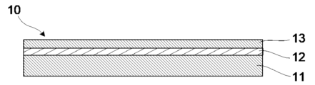
- FIG. 1 is a cross-sectional view showing an example of a laminate according to the present invention.
- FIG. 1 is a cross-sectional view showing an example of an electroless copper layer laminate according to the present invention.
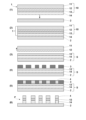
- FIG. 1 is a diagram showing a manufacturing process flow of a printed wiring board using the electroless copper layer laminate of the present invention.
- FIG. 1 is a diagram showing a manufacturing process flow for removing an electroless plating catalyst layer in the manufacturing process flow for a printed wiring board using the electroless copper layer laminate of the present invention.
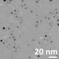
- 1 is a transmission electron microscope image of Pd particles obtained in Synthesis Example 2-3.
- 1 is a transmission electron microscope image of Pd particles obtained in Synthesis Example 2-5.
- the laminate 10 of the present invention is formed by laminating (A) a supporting substrate 11, (B) a release layer 12 made of an organic thin film, and (C) an electroless plating catalyst layer 13 in this order.
- the laminate 10 it is also possible to provide a laminate 1 (hereinafter sometimes referred to as "electroless copper layer laminate 1") in which (A) a supporting substrate 11, (B) a release layer 12 made of an organic thin film, (C) an electroless plating catalyst layer 13, and (D) an electroless copper layer 14 are laminated in this order (see FIG. 2).
- the support substrate 11 can be appropriately selected from known materials and is not particularly limited, but specific examples thereof include metal foils such as copper, aluminum, iron, gold, silver, nickel, palladium, molybdenum, or alloy foils thereof; and plastic support substrates such as polyimide, polyetherimide, polyamideimide, polyethylene terephthalate (PET), polyethylene naphthalate, polycarbonate, polyphenylene ether, polyphenylene sulfide, and polyether ether ketone.
- metal foils such as copper, aluminum, iron, gold, silver, nickel, palladium, molybdenum, or alloy foils thereof
- plastic support substrates such as polyimide, polyetherimide, polyamideimide, polyethylene terephthalate (PET), polyethylene naphthalate, polycarbonate, polyphenylene ether, polyphenylene sulfide, and polyether ether ketone.
- a plastic support substrate is preferred because it is expected to reduce the amount of metal used, reduce weight, and improve flatness, and there is no deterioration over time due to oxidation, and polyimide or polyethylene terephthalate is more preferred in terms of heat resistance.
- the thickness of the support substrate 11 there are no particular limitations on the thickness of the support substrate 11, but it may be adjusted appropriately to a thickness that is appropriate for fulfilling the role of the support substrate, and is generally 5 to 100 ⁇ m. From the standpoint of reducing weight and raw material costs, it is preferable for the thickness of the plastic support substrate to be small, and if the thickness of the plastic support substrate is too small, the handleability of the ultra-thin copper foil with carrier decreases. Therefore, the thickness of the carrier is preferably 5 to 100 ⁇ m, and more preferably 10 to 50 ⁇ m.
- the support substrate 11 may be a commercially available product.
- commercially available polyimide products include the “Kapton (registered trademark)” series of polyimide films manufactured by Toray Industries, Inc.
- commercially available polyethylene terephthalate products include the “Cosmoshine (registered trademark)” series of polyethylene terephthalate films manufactured by Toyobo Co., Ltd., the “Tetoron (registered trademark)” series (currently “Toyobo Ester (registered trademark) Film” manufactured by Toyobo Co., Ltd.) manufactured by Teijin Limited, and the “Lumirror” series of polyethylene terephthalate films manufactured by Toray Industries, Inc.
- release layer 12 made of an organic thin film is a layer that has excellent adhesion to the supporting substrate 11 and appropriate adhesion and appropriate release properties to the electroless plating catalyst layer 13, and is a layer that properly fixes the electroless copper layer 14 formed by the electroless plating process onto the supporting substrate 11, and is a layer that allows the electroless copper layer 14 to be peeled off from the supporting substrate 11 together with the electroless plating catalyst layer 13 during press working.
- the release layer 12 is made of an organic thin film and does not contain chromium, which has been used in the formation of release layers in the past, and is therefore expected to reduce the environmental load.
- the release layer 12 is preferably obtained from a release layer-forming composition that contains a thermosetting resin and a fluorine-containing polymer.
- thermosetting resin examples include polyurea resin, polyacrylic resin, polyimide resin, melamine resin, epoxy resin, phenol resin, unsaturated polyester resin, vinyl ester resin, polyurethane resin, silicone resin, etc., with polyurea resin being preferred.
- the above-mentioned polyurea resin is made from polyurea and a crosslinking agent as raw materials, but in the present invention, the above-mentioned polyurea is preferably one that contains a repeating unit represented by the following formula (U1) because of its excellent heat resistance.
- a u1 , A u2 , A u3 , A u4 , A u5 and A u6 are each independently a hydrogen atom, a methyl group or an ethyl group. From the viewpoints of releasability and productivity, it is preferable that A u1 to A u6 are all hydrogen atoms.
- X u1 is a group represented by the following formula (U1-1), (U1-2), (U1-3) or (U1-4).
- R u1 and R u2 each independently represent a hydrogen atom, an alkyl group having 1 to 6 carbon atoms, an alkenyl group having 3 to 6 carbon atoms, a benzyl group, or a phenyl group, the phenyl group being optionally substituted with at least one group selected from the group consisting of an alkyl group having 1 to 6 carbon atoms, a halogen atom, an alkoxy group having 1 to 6 carbon atoms, a nitro group, a cyano group, a hydroxy group, and an alkylthio group having 1 to 6 carbon atoms, and R u1 and R u2 may be bonded to each other to form a ring having 3 to 6 carbon atoms together with the carbon atom to which they are bonded.
- R u3 is an alkyl group having 1 to 6 carbon atoms, an alkenyl group having 3 to 6 carbon atoms, a benzyl group or a phenyl group, and the phenyl group may be substituted with at least one group selected from the group consisting of an alkyl group having 1 to 6 carbon atoms, a halogen atom, an alkoxy group having 1 to 6 carbon atoms, a nitro group, a cyano group, a hydroxy group and an alkylthio group having 1 to 6 carbon atoms.
- Q u1 is a group represented by the following formula (U1-5) or (U1-6).
- X u2 is a group represented by formula (U1-1), formula (U1-2) or formula (U1-4).
- n u1 and n u2 each independently is 0 or 1.
- Q u2 is an alkylene group having 1 to 10 carbon atoms, a phenylene group, a naphthylene group, or an anthrylene group.
- the phenylene group, naphthylene group, and anthrylene group may be substituted with at least one group selected from the group consisting of an alkyl group having 1 to 6 carbon atoms, a halogen atom, an alkoxy group having 1 to 6 carbon atoms, a nitro group, a cyano group, a hydroxy group, and an alkylthio group having 1 to 6 carbon atoms.
- Q u2 is a phenylene group, a naphthylene group, or an anthrylene group
- the position of their bond is not particularly limited. That is, for example, phenylene groups may be bonded at the 1st and 2nd positions, or at the 1st and 3rd positions, or at the 1st and 4th positions; naphthylene groups may be bonded at the 1st and 2nd positions, or at the 1st and 4th positions, or at the 1st and 5th positions, or at the 2nd and 3rd positions; anthrylene groups may be bonded at the 1st and 2nd positions, or at the 1st and 4th positions, or at the 9th and 10th positions, and any of these may be used.
- the alkyl group having 1 to 6 carbon atoms may be linear, branched, or cyclic, and examples thereof include methyl, ethyl, isopropyl, n-butyl, and cyclohexyl groups.
- the alkenyl group having 3 to 6 carbon atoms may be linear, branched, or cyclic, and examples thereof include 2-propenyl and 3-butenyl groups.
- the alkoxy group having 1 to 6 carbon atoms may be linear, branched, or cyclic, and examples thereof include a methoxy group, an ethoxy group, an isopropoxy group, an n-pentyloxy group, and a cyclohexyloxy group.
- the alkylthio group having 1 to 6 carbon atoms may be linear, branched, or cyclic, and examples thereof include a methylthio group, an ethylthio group, an isopropylthio group, an n-pentylthio group, and a cyclohexylthio group.
- halogen atom examples include a fluorine atom, a chlorine atom, a bromine atom, and an iodine atom.
- ring having 3 to 6 carbon atoms formed by the bonding of R u1 and R u2 include a cyclobutane ring, a cyclopentane ring, and a cyclohexane ring.
- the alkylene group having 1 to 10 carbon atoms may be linear, branched, or cyclic, and examples include a methylene group, an ethylene group, a propylene group, a pentamethylene group, a cyclohexylene group, and a 2-methylpropylene group.
- formula (U1) when X u1 is a group represented by formula (U1-2), the structure is represented by formula (U2) below, and when X u1 is a group represented by formula (U1-3), the structure is represented by formula (U3) below.
- R u3 is preferably a 2-propenyl group.
- Q u1 preferably contains a cyclic structure from the viewpoint of the heat resistance of the polyurea of component (A). That is, Q u1 is preferably a group represented by formula (U1-5) or a group represented by formula (U1-6), and Q u2 is preferably a cyclic alkylene group, a phenylene group, a naphthylene group, or an anthrylene group, and more preferably a group represented by formula (U1-5).
- the above polyurea can be synthesized, for example, by referring to International Publication No. 2005/098542.
- the weight average molecular weight (Mw) of the polyurea is preferably 1,000 to 200,000, more preferably 3,000 to 100,000, even more preferably 4,000 to 30,000, and even more preferably 5,000 to 20,000.
- the dispersity (Mw/Mn) is preferably 1.3 to 4.0, and more preferably 1.4 to 2.5.
- Mn is the number average molecular weight, and Mw and Mn are values measured in terms of polystyrene by gel permeation chromatography (GPC).
- the crosslinking agent may be any known agent and is not particularly limited.
- the crosslinking agent is preferably a compound represented by any one of the following formulas (C-1) to (C-5).
- R 11 to R 26 each independently represent a hydrogen atom or an alkyl group having 1 to 6 carbon atoms, preferably an alkyl group having 1 to 6 carbon atoms, and R 27 represents a hydrogen atom or a methyl group.
- crosslinking agent examples include nitrogen-containing compounds such as hexamethylol melamine, tetramethylol benzoguanamine, 1,3,4,6-tetramethylol glycoluril, hexamethoxymethyl melamine, tetramethoxymethyl benzoguanamine, 1,3,4,6-tetrakis(methoxymethyl) glycoluril, 1,3,4,6-tetrakis(butoxymethyl) glycoluril, and 1,3,4,6-tetrakis(hydroxymethyl) glycoluril.
- nitrogen-containing compounds such as hexamethylol melamine, tetramethylol benzoguanamine, 1,3,4,6-tetramethylol glycoluril, hexamethoxymethyl melamine, tetramethoxymethyl benzoguanamine, 1,3,4,6-tetrakis(methoxymethyl) glycoluril, 1,3,4,6-tetrakis(butoxymethyl) glycoluril,
- nitrogen-containing compounds such as methoxymethyl type melamine compounds (product names: Cymel (registered trademark) 300, Cymel 301, Cymel 303, Cymel 350), butoxymethyl type melamine compounds (product names: Mycoat (registered trademark) 506, Mycoat 508), glycoluril compounds (product names: Cymel 1170, POWDERLINK 1174), methylated urea resins (product names: UFR65), butylated urea resins (product names: UFR300, U-VAN10S60, U-VAN10R, U-VAN11HV), and urea/formaldehyde resins (product names: Beckamine (registered trademark) J-300S, Beckamine P-955, Beckamine N) manufactured by Allnex Corporation.
- methoxymethyl type melamine compounds product names: Cymel (registered trademark) 300, Cymel 301, Cymel 303, Cymel 350
- butoxymethyl type melamine compounds product names: Mycoat (registered trademark) 506,
- a crosslinking agent a polymer produced using a (meth)acrylamide compound substituted with a hydroxymethyl group or an alkoxymethyl group, such as N-hydroxymethyl(meth)acrylamide, N-methoxymethyl(meth)acrylamide, N-ethoxymethyl(meth)acrylamide, or N-butoxymethyl(meth)acrylamide, can be used.
- polymers examples include poly(N-butoxymethyl(meth)acrylamide), a copolymer of N-butoxymethyl(meth)acrylamide and styrene, a copolymer of N-hydroxymethyl(meth)acrylamide and methyl(meth)acrylate, a copolymer of N-ethoxymethylmethacrylamide and benzyl methacrylate, and a copolymer of N-butoxymethyl(meth)acrylamide, benzyl(meth)acrylate, and 2-hydroxypropyl(meth)acrylate.
- crosslinking agent examples include hexamethoxymethylmelamine, tetramethoxymethylbenzoguanamine, 1,3,4,6-tetrakis(methoxymethyl)glycoluril (POWDERLINK 1174), 1,3,4,6-tetrakis(butoxymethyl)glycoluril, and 1,3,4,6-tetrakis(hydroxymethyl)glycoluril.
- crosslinking agents can undergo a crosslinking reaction by self-condensation. They can also undergo a crosslinking reaction with the hydroxyl groups in the polyurea. This crosslinking reaction makes the resulting release layer 12 strong and less soluble in organic solvents.
- the content of the crosslinking agent is preferably 10 to 100 parts by mass, more preferably 20 to 50 parts by mass, per 100 parts by mass of the polyurea. If the content of the crosslinking agent is within the above range, a composition can be obtained that has appropriate peelability and can provide a release layer 12 that has excellent stability after film formation.
- the above crosslinking agents may be used alone or in combination of two or more types.
- the fluorine-containing polymer may be any known polymer and is not particularly limited. Specific examples include the fluorine polymers described in WO 2020/158521 and WO 2021/132383. In the present invention, a polymer containing a repeating unit represented by the following formula (a1), a repeating unit represented by the following formula (b), and a repeating unit represented by the following formula (c) is preferred.
- each R A is independently a hydrogen atom or a methyl group.
- R B1 is a branched alkyl group having 3 or 4 carbon atoms in which at least one hydrogen atom is substituted with a fluorine atom.
- R C is an alkyl group having 1 to 10 carbon atoms and having a hydroxy group, or a polycyclic alkyl group having 6 to 20 carbon atoms and having a hydroxy group.
- R D is an alkyl group having 1 to 10 carbon atoms which may be substituted with a polycyclic alkyl group having 6 to 20 carbon atoms, a polycyclic alkyl group having 6 to 20 carbon atoms, or an aryl group having 6 to 12 carbon atoms.
- Examples of the branched alkyl group having 3 or 4 carbon atoms include an isopropyl group, an isobutyl group, a sec-butyl group, and a tert-butyl group.
- R is preferably a branched alkyl group in which at least one hydrogen atom is substituted with a fluorine atom, and specific examples include a 1,1,1-trifluoroisopropyl group, a 1,1,1,3,3,3-hexafluoroisopropyl group, and a nonafluorotert-butyl group.
- alkyl groups having 1 to 10 carbon atoms and a hydroxy group include hydroxymethyl, 2-hydroxyethyl, 3-hydroxypropyl, 4-hydroxybutyl, 5-hydroxypentyl, 6-hydroxyhexyl, 7-hydroxyheptyl, 8-hydroxyoctyl, 9-hydroxynonyl, 10-hydroxydecyl, 2-hydroxy-1-methylethyl, 2-hydroxy-1,1-dimethylethyl, 3-hydroxy-1-methylpropyl, 3-hydroxy-2-methylpropyl, 3-hydroxy-1,1-dimethylpropyl, 3-hydroxy-1,2-dimethylpropyl, 3-hydroxy-2,2-dimethylpropyl, 4-hydroxy-1-methylbutyl, 4-hydroxypropyl, 5 ...
- Hydroxyalkyl groups having 2 to 10 carbon atoms such as 4-hydroxy-2-methylbutyl and 4-hydroxy-3-methylbutyl, in which the carbon atom to which the hydroxy group is bonded is a primary carbon atom; hydroxyalkyl groups having 1 to 10 carbon atoms, such as 1-hydroxyethyl, 1-hydroxypropyl, 2-hydroxypropyl, 1-hydroxybutyl, 2-hydroxybutyl, 1-hydroxyhexyl, 2-hydroxyhexyl, 1-hydroxyoctyl, 2-hydroxyoctyl, 1-hydroxydecyl, 2-hydroxydecyl, 1-hydroxy-1-methylethyl, and 2-hydroxy-2-methylpropyl, in which the carbon atom to which the hydroxy group is bonded is a secondary or tertiary carbon atom.
- Examples of the polycyclic alkyl group having 6 to 20 carbon atoms include 1-adamantyl group, 2-adamantyl group, isobornyl group, and norbornyl group.
- Examples of the aryl group having 6 to 12 carbon atoms include phenyl group, 1-naphthyl group, 2-naphthyl group, 1-biphenyl group, and 2-biphenyl group.
- Examples of the polycyclic alkyl groups having 6 to 20 carbon atoms and a hydroxy group include 3-hydroxy-1-adamantyl group, 4-hydroxy-1-adamantyl group, 5-hydroxy-1-adamantyl group, 3-hydroxy-2-adamantyl group, 4-hydroxy-2-adamantyl group, 5-hydroxy-2-adamantyl group, and hydroxynorbornyl group, and examples of the aryl groups having 6 to 12 carbon atoms and a hydroxy group include 4-hydroxyphenyl group and 3-hydroxyphenyl group.
- the fluorine-containing polymer may also contain a repeating unit represented by the following formula (a2), a repeating unit represented by the following formula (b), a repeating unit represented by the following formula (c), and a repeating unit represented by the following formula (d).
- R A , R C and R D are the same as above.
- R B2 is a branched alkyl group having 3 or 4 carbon atoms in which at least one hydrogen atom is substituted with a fluorine atom (excluding 2-methyl-1,1,1,3,3,3-hexafluoroisopropyl group). Examples of the branched alkyl group having 3 or 4 carbon atoms include the same as those described above.
- R E is a single bond, a polycyclic alkylene group having 6 to 20 carbon atoms, or an arylene group having 6 to 12 carbon atoms.
- R F is a single bond or an alkylene group having 1 to 10 carbon atoms.
- R G is a methyl group, an ethyl group, or a hydroxy group.
- the polycyclic alkylene group having 6 to 20 carbon atoms includes groups in which one hydrogen atom has been removed from the specific examples of polycyclic alkyl groups having 6 to 20 carbon atoms described above, such as an adamantylene group, an isobornylene group, and a norbornylene group.
- the above-mentioned arylene group having 6 to 12 carbon atoms includes groups in which one hydrogen atom has been removed from the specific examples of the above-mentioned aryl group having 6 to 12 carbon atoms, such as a phenylene group, a naphthylene group, and a biphenylylene group.
- alkylene group having 1 to 10 carbon atoms examples include the same as those exemplified in the description of Q u2 above.
- an alkylene group having 1 to 5 carbon atoms is preferred, a methylene group and an ethylene group are more preferred, and a methylene group is even more preferred.
- repeating unit represented by formula (a1) or (a2) examples include, but are not limited to, those represented by the following formulae (a-1) to (a-3), where R A is the same as defined above.
- repeating unit represented by formula (b) examples include, but are not limited to, those represented by the following formulae (b-1) to (b-17), in which R A is the same as defined above.
- repeating unit represented by formula (c) examples include, but are not limited to, those represented by the following formulae (c-1) to (c-15), in which R A is the same as defined above.
- repeating unit represented by formula (d) examples include, but are not limited to, those represented by the following formulae (d-1) to (d-8), where R A is the same as defined above.
- the fluorine-containing polymer contains a repeating unit represented by formula (a1), a repeating unit represented by formula (b), and a repeating unit represented by formula (c), and the carbon atom to which the hydroxy group is bonded in the hydroxyalkyl group in the repeating unit represented by formula (b) is a secondary or tertiary carbon atom (hereinafter, such a fluorine-containing polymer will be referred to as fluorine-containing polymer D1)
- the content of the repeating unit represented by formula (a1) is preferably 30 to 60 mol %, more preferably 35 to 50 mol %, of all repeating units.
- the content of the repeating unit represented by formula (b) is preferably 10 to 35 mol %, more preferably 15 to 30 mol %, of all repeating units.
- the content of the repeating unit represented by formula (c) is preferably 5 to 60 mol %, more preferably 20 to 50 mol %, of all repeating units.
- the fluorine-containing polymer contains a repeating unit represented by formula (a1), a repeating unit represented by formula (b), and a repeating unit represented by formula (c), and the carbon atom to which the hydroxy group is bonded in the hydroxyalkyl group in the repeating unit represented by formula (b) is a primary carbon atom (hereinafter, such a fluorine-containing polymer will be referred to as fluorine-containing polymer D2)
- the content of the repeating unit represented by formula (a1) in all repeating units is preferably 15 to 60 mol%, more preferably 25 to 60 mol%, even more preferably 30 to 60 mol%, and even more preferably 35 to 50 mol%.
- the content of the repeating unit represented by formula (b) in all repeating units is preferably 8 to 38 mol%, preferably 10 to 38 mol%, more preferably 10 to 35 mol%, and even more preferably 15 to 30 mol%.
- the content of the repeating unit represented by formula (c) in all repeating units is preferably 2 to 77 mol%, more preferably 2 to 65 mol%, even more preferably 5 to 60 mol%, and even more preferably 20 to 50 mol%.
- the fluorine-containing polymer contains a repeating unit represented by formula (a2), a repeating unit represented by formula (b), a repeating unit represented by formula (c) and a repeating unit represented by formula (d) (hereinafter, such a fluorine-containing polymer will be referred to as fluorine-containing polymer D3)
- the content of the repeating unit represented by formula (a2) is preferably 2 to 45 mol %, more preferably 5 to 35 mol %, of all repeating units.
- the content of the repeating unit represented by formula (b) is preferably 20 to 35 mol %, more preferably 25 to 35 mol %, of all repeating units.
- the content of the repeating unit represented by formula (c) is preferably 30 to 45 mol %, more preferably 35 to 45 mol %, of all repeating units.
- the content of the repeating unit represented by formula (d) is preferably 5 to 18 mol %, more preferably 5 to 15 mol %, of all repeating units.
- the Mw of the fluorine-containing polymer is preferably 2,000 to 10,000, and more preferably 3,000 to 6,000.
- the Mw/Mn is preferably 1.0 to 2.1, and more preferably 1.0 to 1.9.
- the content of the fluorine-containing polymer is 5 to 100 parts by mass per 100 parts by mass of the polyurea. By keeping the content of the fluorine-containing polymer within the above range, good coatability and appropriate peelability can be obtained.
- the content is preferably 10 to 100 parts by mass, more preferably 20 to 100 parts by mass, and even more preferably 30 to 100 parts by mass, relative to 100 parts by mass of the polyurea.
- the content is preferably 5 to 80 parts by mass, and more preferably 5 to 50 parts by mass, relative to 100 parts by mass of the polyurea.
- the above fluorine-containing polymers may be used alone or in combination of two or more.
- the composition for forming a release layer of the present invention may contain an acid compound or a salt thereof.
- the acid compound include sulfonic acid compounds such as p-toluenesulfonic acid, trifluoromethanesulfonic acid, pyridinium p-toluenesulfonate, salicylic acid, camphorsulfonic acid, sulfosalicylic acid, 4-chlorobenzenesulfonic acid, 4-hydroxybenzenesulfonic acid, benzenedisulfonic acid, dodecylbenzenesulfonic acid, 1-naphthalenesulfonic acid, and pyridinium 1-naphthalenesulfonic acid, and carboxylic acid compounds such as salicylic acid, sulfosalicylic acid, citric acid, benzoic acid, and hydroxybenzoic acid.
- Examples of the salts of the above acid compounds include pyridinium salts, isopropanolamine salts, and N-methylmorpholine salts of the above acids, and more specifically, pyridinium p-toluenesulfonate, pyridinium 1-naphthalenesulfonate, isopropanolamine p-toluenesulfonate, and N-methylmorpholine p-toluenesulfonate.
- the content of the acid compound or a salt thereof is preferably 0.01 to 15 parts by mass, and more preferably 0.1 to 10 parts by mass, relative to 100 parts by mass of the polyurea.
- the content of the acid compound or a salt thereof is within the above range, a composition can be obtained that has high heat resistance and appropriate release properties, and can provide a release layer 12 that has excellent stability after film formation.
- the acid compound or a salt thereof may be used alone or in combination of two or more types.
- the release layer-forming composition may contain a solvent.
- the solvent is not particularly limited in type, structure, etc., as long as it can dissolve the above-mentioned components and other additives described later.
- glycol ether-based solvents having 3 to 20 carbon atoms, ester-based solvents having 3 to 20 carbon atoms, ketone-based solvents having 3 to 20 carbon atoms, or cyclic compound-based solvents having 3 to 20 carbon atoms are preferred.
- glycol ether solvents include propylene glycol monomethyl ether (PGME), propylene glycol monomethyl ether acetate (PGMEA), propylene glycol monoethyl ether, propylene glycol monoethyl ether acetate, propylene glycol monopropyl ether, propylene glycol monobutyl ether, ethylene glycol monomethyl ether, ethylene glycol dimethyl ether, ethylene glycol diethyl ether, ethylene glycol monomethyl ether acetate, diethylene glycol monomethyl ether, diethylene glycol monoethyl ether, diethylene glycol dimethyl ether (Diglyme), diethylene glycol diethyl ether, and diethylene glycol.
- PGME propylene glycol monomethyl ether
- PMEA propylene glycol monomethyl ether acetate
- PGMEA propylene glycol monoethyl ether
- propylene glycol monoethyl ether acetate propylene glyco
- ethers examples include monohexyl ether, diethylene glycol butyl methyl ether, triethylene glycol monomethyl ether, triethylene glycol dimethyl ether (Triglyme), diethylene glycol monobutyl ether, diethylene glycol ethyl methyl ether, diethylene glycol isopropyl methyl ether, diethylene glycol dibutyl ether, dimethoxytetraethylene glycol, dipropylene glycol methyl ether, dipropylene glycol dimethyl ether, dipropylene glycol monomethyl ether, diethylene glycol monoethyl ether acetate (DEGEEA), methoxymethylbutanol, tripropylene glycol dimethyl ether, and triethylene glycol butyl methyl ether.
- Triglyme triethylene glycol monomethyl ether
- diethylene glycol ethyl methyl ether diethylene glycol isopropyl methyl ether
- diethylene glycol dibutyl ether dimethoxyt
- ester solvents examples include ethyl acetate, propyl acetate, butyl acetate, isobutyl acetate, ethyl lactate, ⁇ -butyrolactone, methyl 2-hydroxyisobutyrate, ethyl 2-hydroxyisobutyrate, methyl methoxypropionate, and ethyl ethoxypropionate.
- ketone solvents examples include methyl ethyl ketone, cyclohexanone, cyclopentanone, benzophenone, etc.
- Examples of the cyclic compound solvent include N-methylpyrrolidone and ⁇ -butyrolactone.
- the content of the solvent is preferably an amount that results in a solids concentration in the release layer forming composition of the present invention of 0.1 to 40 mass%, more preferably an amount that results in a solids concentration in the release layer forming composition of the present invention of 0.5 to 20 mass%, and even more preferably an amount that results in a solids concentration in the release layer forming composition of the present invention of 0.5 to 10 mass%.
- the solids are a general term for all components of the release layer forming composition other than the solvent.
- the above-mentioned solvents may be used alone or in a mixture of two or more types.
- the above-mentioned release layer forming composition may contain a surfactant as necessary.By adding a surfactant, the coating property of the release layer forming composition on the substrate can be improved.As the above-mentioned surfactant, a known surfactant such as a nonionic surfactant, a fluorine-based surfactant, or a silicone-based surfactant can be used.
- nonionic surfactants include polyoxyethylene alkyl ethers such as polyoxyethylene lauryl ether, polyoxyethylene stearyl ether, polyoxyethylene cetyl ether, and polyoxyethylene oleyl ether; polyoxyethylene alkylaryl ethers such as polyoxyethylene octylphenyl ether and polyoxyethylene nonylphenyl ether; polyoxyethylene-polyoxypropylene block copolymers; sorbitan fatty acid esters such as sorbitan monolaurate, sorbitan monopalmitate, sorbitan monostearate, sorbitan monooleate, sorbitan trioleate, and sorbitan tristearate; and polyoxyethylene sorbitan fatty acid esters such as polyoxyethylene sorbitan monolaurate, polyoxyethylene sorbitan monopalmitate, polyoxyethylene sorbitan monostearate, polyoxyethylene sorbitan trioleate, and polyoxyethylene sorbitan tristearate.
- fluorine-based surfactants examples include EFTOP (registered trademark) EF301, EF303, EF352 (manufactured by Mitsubishi Materials Electronic Chemicals Co., Ltd.), Megafac (registered trademark) F171, F173, F554, F559, F563, R-30, R-40, R-40-LM, DS-21 (manufactured by DIC Corporation), FLUORAD (registered trademark) FC430, FC431 (manufactured by 3M), Asahiguard (registered trademark) AG710, Surflon (registered trademark) S-382, SC101, SC102, SC103, SC104, SC105, SC106 (manufactured by AGC Corporation), etc.
- EFTOP registered trademark
- EF301 EF301
- EF303 EF352
- Megafac registered trademark
- F171, F173, F554, F559, F563, R-30, R-40, R-40-LM examples of the fluorine-based surfact
- silicone surfactant is organosiloxane polymer KP341 (manufactured by Shin-Etsu Chemical Co., Ltd.).
- the release layer forming composition contains a surfactant
- the content is preferably 0.0001 to 1 part by mass, and more preferably 0.001 to 0.5 parts by mass, per 100 parts by mass of the polyurea.
- the surfactant may be used alone or in combination of two or more kinds.
- the release layer-forming composition may also contain other additives, such as silane coupling agents, rheology modifiers, pigments, dyes, storage stabilizers, defoamers, and antioxidants, as long as the effects of the present invention are not impaired.
- additives such as silane coupling agents, rheology modifiers, pigments, dyes, storage stabilizers, defoamers, and antioxidants, as long as the effects of the present invention are not impaired.
- the preparation method of the above-mentioned release layer forming composition is not particularly limited.
- the preparation method can be, for example, a method of mixing a crosslinking agent, a fluorine-containing polymer, an acid compound or its salt, and a solvent etc. in a predetermined ratio with a solution of polyurea dissolved in a solvent to make a homogeneous solution, or a method of further adding and mixing other additives as necessary at an appropriate stage of the above-mentioned preparation method.
- the solution of the specific copolymer (polymer) obtained by the polymerization reaction in the solvent can be used as is.
- an acid compound or its salt, a crosslinking agent, a fluorine-containing polymer, a solvent, etc. are added to the polyurea solution in the same manner as above to make a homogeneous solution.
- additional solvent may be added for the purpose of adjusting the concentration.
- the solvent used in the polyurea production process and the solvent used to adjust the concentration of the release layer forming composition may be the same or different.
- the prepared solution of the composition for forming the release layer using a filter with a pore size of about 0.2 ⁇ m before use.
- the viscosity of the release layer-forming composition is set appropriately taking into consideration the thickness of the release layer 12 to be produced, but when the goal is to reproducibly obtain a film having a thickness of about 0.01 to 5 ⁇ m, the viscosity is usually about 1 to 5,000 mPa ⁇ s at 25°C, and preferably about 1 to 2,000 mPa ⁇ s.
- the viscosity can be measured using a commercially available viscometer for measuring the viscosity of liquids, for example, by referring to the procedure described in JIS K7117-2, at a composition temperature of 25°C.
- a cone-plate type rotational viscometer is used as the viscometer, and preferably the same type of viscometer is used with a standard cone rotor of 1°34' x R24, and the viscosity can be measured at a composition temperature of 25°C.
- An example of such a rotational viscometer is the TVE-25L manufactured by Toki Sangyo Co., Ltd.
- release layer 12 made of organic thin film The above-mentioned composition for forming a release layer can be applied onto a supporting substrate 11, and then a firing method including a step of firing at 180 to 250°C can be used to obtain a release layer 12 having excellent adhesion to the supporting substrate 11, as well as appropriate adhesion to and releasability with the electroless plating catalyst layer 13.
- the heating time varies depending on the heating temperature and cannot be generally specified, but is usually between 1 minute and 5 hours.
- the baking temperature may include a step of baking at a temperature lower than that.
- a preferred example of the heating mode in the present invention is to heat at 50 to 150°C for 1 minute to 1 hour, and then increase the heating temperature to 180 to 250°C for 5 minutes to 4 hours.
- a particularly preferred example of the heating mode is to heat at 50 to 150°C for 1 minute to 1 hour, and then heat at 200 to 250°C for 5 minutes to 2 hours.
- Another preferred example of the heating mode is to heat at 50 to 150°C for 1 to 30 minutes, and then heat at 200 to 250°C for 5 minutes to 1 hour.
- the coating method is not particularly limited, but examples include cast coating, spin coating, blade coating, dip coating, roll coating, bar coating, die coating, inkjet printing, and printing methods (relief printing, intaglio printing, planographic printing, screen printing, etc.).
- Examples of equipment used for heating include hot plates and ovens.
- the heating atmosphere may be air or an inert gas, and may be normal pressure or reduced pressure.
- the thickness of the release layer 12 is usually about 0.01 to 50 ⁇ m, and from the viewpoint of productivity, is preferably about 0.01 to 30 ⁇ m, and more preferably about 0.01 to 20 ⁇ m. The thickness of the coating film before heating is adjusted to achieve the desired thickness.
- the release layer 12 has excellent adhesion to the support substrate 11, particularly to the plastic support substrate, and also has moderate adhesion to and moderate release properties with the electroless plating catalyst layer 13. Therefore, the release layer 12 can be transferred onto the resin substrate during press processing without damaging the electroless copper layer 14. Furthermore, since it does not contain chromium, it has a low environmental impact.
- Electroless plating catalyst layer 13 is a base layer for forming an electroless copper layer 14 described below on the release layer 12 consisting of an organic thin film, and is a layer formed from a base agent containing a polymer having an alkoxy group, a hydroxy group, an ammonium group, a carboxy group or a cyano group, and metal fine particles.
- the above polymer is preferably a hyperbranched polymer.
- a hyperbranched polymer is, for example, a highly branched polymer with an irregular branched structure obtained by polymerizing ABx type multifunctional monomers (where A and B are functional groups that react with each other, and the number of Bs, X, is 2 or more).
- the hyperbranched polymer is preferably a hyperbranched polymer represented by the following formula [1], which has a weight average molecular weight of 500 to 5,000,000.
- each R 1 independently represents a hydrogen atom or a methyl group.
- R 2 , R 3 and R 4 each independently represent a hydrogen atom, a linear, branched or cyclic alkyl group having 1 to 20 carbon atoms, an arylalkyl group having 7 to 20 carbon atoms, or --(CH 2 CH 2 O) m R 5 (wherein R 5 represents a hydrogen atom or a methyl group, and m represents any integer from 2 to 100).
- the alkyl and arylalkyl groups may be substituted with an alkoxy, hydroxy, ammonium, carboxyl or cyano group.
- R2 , R3 and R4 may be taken together to represent a linear, branched or cyclic alkylene group, or R2 , R3 and R4 and the nitrogen atom to which they are attached may be taken together to form a ring.
- X ⁇ represents an anion.
- n is the number of repeating structural units and represents an integer of 2 to 100,000.
- Examples of the linear alkyl group having 1 to 20 carbon atoms in R 2 , R 3 and R 4 include a methyl group, an ethyl group, an n-propyl group, an n-butyl group, an n-pentyl group, an n-hexyl group, an n-heptyl group, an n-octyl group, an n-nonyl group, an n-decyl group, an n-undecyl group, an n-dodecyl group, an n-tridecyl group, an n-tetradecyl group, an n-pentadecyl group, an n-hexadecyl group, an n-heptadecyl group, an n-octadecyl group, an n-nonadecyl group and an n-eicosyl group, and in that the undercoat agent is less likely to dissolve
- Examples of the branched alkyl group include an isopropyl group, an isobutyl group, a sec-butyl group and a tert-butyl group.
- Examples of the cyclic alkyl group include groups having a cyclopentyl ring or a cyclohexyl ring structure.
- Examples of the arylalkyl group having 7 to 20 carbon atoms in R 2 , R 3 and R 4 include a benzyl group and a phenethyl group.
- Examples of linear alkylene groups formed by combining two of the above R 2 , R 3 and R 4 groups include methylene, ethylene, n-propylene, n-butylene and n-hexylene groups.
- Examples of branched alkylene groups include isopropylene, isobutylene and 2-methylpropylene groups.
- Examples of cyclic alkylene groups include alicyclic aliphatic groups having a monocyclic, polycyclic or bridged cyclic structure with 3 to 30 carbon atoms. Specific examples include groups having a monocyclo, bicyclo, tricyclo, tetracyclo or pentacyclo structure with 4 or more carbon atoms. These alkylene groups may contain a nitrogen atom, a sulfur atom or an oxygen atom in the group.
- the ring formed by R2 , R3, and R4 together with the nitrogen atom bonded thereto may contain a nitrogen atom, a sulfur atom, or an oxygen atom in the ring, and examples thereof include a pyridine ring, a pyrimidine ring, a pyrazine ring, a quinoline ring, and a bipyridyl ring.
- the anion of X ⁇ is preferably a halogen atom, PF 6 ⁇ , BF 4 ⁇ or a perfluoroalkanesulfonate.
- a 1 represents a structure represented by the following formula [2].
- a 2 represents a linear, branched or cyclic alkylene group having 1 to 30 carbon atoms which may contain an ether bond or an ester bond.
- Y 1 , Y 2 , Y 3 and Y 4 each independently represent a hydrogen atom, an alkyl group having 1 to 20 carbon atoms, an alkoxy group having 1 to 20 carbon atoms, a nitro group, a hydroxyl group, an amino group, a carboxyl group or a cyano group.
- alkylene group of A2 examples include linear alkylene groups such as methylene, ethylene, n-propylene, n-butylene, and n-hexylene, and branched alkylene groups such as isopropylene, isobutylene, and 2-methylpropylene.
- cyclic alkylene group examples include alicyclic aliphatic groups having a monocyclic, polycyclic, or crosslinked ring structure with 3 to 30 carbon atoms. Specific examples include groups having a monocyclo, bicyclo, tricyclo, tetracyclo, or pentacyclo structure with 4 or more carbon atoms.
- Examples of the structure of the alicyclic portion of the alicyclic aliphatic group include, but are not limited to, the structures represented by the following formulas (a) to (s).
- examples of the alkyl group having 1 to 20 carbon atoms for Y1 , Y2 , Y3 , and Y4 in the above formula [2] include a methyl group, an ethyl group, an isopropyl group, a cyclohexyl group, and an n-pentyl group.
- examples of the alkoxy group having 1 to 20 carbon atoms include a methoxy group, an ethoxy group, an isopropoxy group, a cyclohexyloxy group, and an n-pentyloxy group. It is preferable that Y1 , Y2 , Y3 , and Y4 are each independently a hydrogen atom or an alkyl group having 1 to 20 carbon atoms.
- the above A 1 is preferably a structure represented by the following formula [4].
- a suitable embodiment of the hyperbranched polymer represented by the above formula [1] is the hyperbranched polymer represented by the following formula [3], but is not limited to this.
- the weight average molecular weight Mw of the hyperbranched polymer is preferably 500 to 5,000,000, more preferably 1,000 to 1,000,000, even more preferably 2,000 to 500,000, and even more preferably 3,000 to 200,000.
- the dispersity: Mw (weight average molecular weight)/Mn (number average molecular weight) is preferably 1.0 to 7.0, more preferably 1.1 to 6.0, and even more preferably 1.2 to 5.0.
- the weight average molecular weight Mw is a polystyrene equivalent value measured by gel permeation chromatography.
- the hyperbranched polymer represented by the above formula [1] can be synthesized by a known method, for example, the method described in International Publication No. 2012/141215 can be referred to, and the hyperbranched polymer can be obtained by reacting an amine compound with a hyperbranched polymer having halogen atoms at the molecular terminals.
- the hyperbranched polymer having halogen atoms at the molecular end can be produced from a hyperbranched polymer having dithiocarbamate groups at the molecular end, according to the description in WO 2008/029688.
- the hyperbranched polymer having dithiocarbamate groups at the molecular end can be a commercially available product, and Hypertech (registered trademark) HPS-200 manufactured by Nissan Chemical Industries, Ltd. can be suitably used.
- the metal microparticles may be any known metal, and are not particularly limited.
- Metal species include iron (Fe), cobalt (Co), nickel (Ni), copper (Cu), palladium (Pd), silver (Ag), tin (Sn), platinum (Pt) and gold (Au).
- one of these metals may be used, or an alloy of two or more of them may be used.
- palladium microparticles are preferred.
- oxides of the above metals may also be used as the metal microparticles.
- the metal microparticles can be obtained by reducing metal ions, for example, by irradiating an aqueous solution of metal salts with light from a high-pressure mercury lamp or by adding a compound with a reducing effect (a so-called reducing agent) to the aqueous solution.
- a reducing agent a compound with a reducing effect
- an aqueous solution of metal salts can be added to a solution in which the hyperbranched polymer is dissolved and then irradiated with ultraviolet light, or an aqueous solution of metal salts and a reducing agent can be added to the solution to reduce the metal ions, thereby forming a complex of the hyperbranched polymer and metal microparticles, and a base agent containing the hyperbranched polymer and metal microparticles can be prepared.
- the reducing agent is not particularly limited, and various reducing agents can be used. It is preferable to select the reducing agent depending on the type of metal contained in the resulting base agent.
- reducing agents include metal borohydrides such as sodium borohydride and potassium borohydride; aluminum hydride salts such as lithium aluminum hydride, potassium aluminum hydride, cesium aluminum hydride, beryllium aluminum hydride, magnesium aluminum hydride, and calcium aluminum hydride; hydrazine compounds; citric acid and its salts; succinic acid and its salts; ascorbic acid and its salts; primary or secondary alcohols such as methanol, ethanol, isopropanol, and polyols; trimethylamine, triethylamine, diisopropylethylamine, diethylmethylamine, and ethylmethylamine.
- tertiary amines such as amine, tetramethylethylenediamine [TMEDA], and ethylenediaminetetraacetic acid [EDTA]; hydroxylamine; and phosphines such as tri-n-propylphosphine, tri-n-butylphosphine, tricyclohexylphosphine, tribenzylphosphine, triphenylphosphine, triethoxyphosphine, 1,2-bis(diphenylphosphino)ethane [DPPE], 1,3-bis(diphenylphosphino)propane [DPPP], 1,1'-bis(diphenylphosphino)ferrocene [DPPF], and 2,2'-bis(diphenylphosphino)-1,1'-binaphthyl [BINAP].
- DPPE 1,2-bis(diphenylphosphino)ethane
- DPPP 1,3-bis(diphenylpho
- the average particle size of the metal particles is preferably 1 to 100 nm. This is because if the average particle size of the metal particles exceeds 100 nm, the surface area decreases and the catalytic activity decreases.
- the average particle size is more preferably 75 nm or less, and particularly preferably 1 to 30 nm.
- the content of the hyperbranched polymer in the primer is preferably 50 to 2,000 parts by mass per 100 parts by mass of the metal microparticles. If it is less than 50 parts by mass, the dispersibility of the metal microparticles is insufficient, and if it exceeds 2,000 parts by mass, the organic matter content increases, making it more likely that problems will occur in the physical properties, etc. More preferably, it is 100 to 1,000 parts by mass.
- the above-mentioned base agent contains the above-mentioned hyperbranched polymer having the ammonium group at the molecular end and metal fine particles, and in this case, it is preferable that the hyperbranched polymer and the metal fine particles form a complex.
- the complex is a particulate form in which the two coexist in contact with or in close proximity to the metal fine particles due to the action of the ammonium group at the end of the hyperbranched polymer, in other words, it is expressed as a complex having a structure in which the ammonium group of the hyperbranched polymer is attached to or coordinated with the metal fine particles.
- the "composite” in the present invention may include not only a composite in which metal microparticles and a hyperbranched polymer are bonded to form a single composite as described above, but also a composite in which metal microparticles and a hyperbranched polymer exist independently of each other without forming a bond.
- the formation of a complex between the hyperbranched polymer and metal particles is carried out simultaneously with the preparation of a base agent containing the hyperbranched polymer and metal particles.
- Methods for this include synthesizing metal particles stabilized to a certain extent by lower ammonium ligands and then exchanging the ligands with the hyperbranched polymer, and forming a complex by directly reducing metal ions in a solution of a hyperbranched polymer having ammonium groups.
- a complex can also be formed by reducing the metal ions by adding an aqueous solution of a metal salt to a solution in which the hyperbranched polymer is dissolved and irradiating the solution with ultraviolet light, or by adding an aqueous solution of a metal salt and a reducing agent to the solution.
- metal microparticles stabilized to a certain extent by the raw material lower ammonium ligands can be synthesized by the method described in Journal of Organometallic Chemistry 1996, 520, 143-162, etc.
- the desired metal microparticle composite can be obtained by dissolving a hyperbranched polymer having ammonium groups in the resulting reaction mixture solution of metal microparticles and stirring at room temperature (approximately 25°C) or with heating.
- the solvent used is not particularly limited as long as it is capable of dissolving the hyperbranched polymer and metal particles at the required concentration or higher, but specific examples include alcohols such as ethanol, propanol, isopropanol, etc.; halogenated hydrocarbons such as methylene chloride and chloroform; cyclic ethers such as tetrahydrofuran, 2-methyltetrahydrofuran, tetrahydropyran, etc.; nitriles such as acetonitrile and butyronitrile, etc., and mixtures of these solvents. Among these, tetrahydrofuran is preferred in the present invention.
- the temperature at which the reaction mixture of metal particles and the hyperbranched polymer having ammonium groups are mixed can usually be in the range of 0°C to the boiling point of the solvent used, and is preferably in the range of room temperature (approximately 25°C) to 60°C.
- metal particles can be stabilized to some extent in advance by using a phosphine-based dispersant (phosphine ligand) in addition to an amine-based dispersant (lower ammonium ligand).
- phosphine ligand phosphine ligand
- amine-based dispersant lower ammonium ligand
- a hyperbranched polymer having metal ions and ammonium groups is dissolved in a solvent and reacted in a hydrogen gas atmosphere to obtain the desired metal fine particle composite.
- the metal ion source used here may be the above-mentioned metal salt or a metal carbonyl complex such as chromium hexacarbonyl [Cr(CO) 6 ], iron pentacarbonyl [Fe(Co) 5 ], dicobalt octacarbonyl [ Co2 (CO) 8 ], nickel tetracarbonyl [Ni(CO) 4 ], etc.
- nickel tetracarbonyl [Ni(CO) 4 ] etc.
- zero-valent metal complexes such as metal olefin complexes, metal pho
- the solvent to be used is not particularly limited as long as it can dissolve the hyperbranched polymer having metal ions and ammonium groups at a required concentration or more, but specific examples include alcohols such as ethanol and propanol, halogenated hydrocarbons such as methylene chloride and chloroform, cyclic ethers such as tetrahydrofuran, 2-methyltetrahydrofuran, and tetrahydropyran, nitriles such as acetonitrile and butyronitrile, and mixtures of these solvents. Among these, tetrahydrofuran is preferred in the present invention.
- the temperature at which the metal ions and the hyperbranched polymer having an ammonium group are mixed can usually be in the range of 0° C. to the boiling point of the solvent used.
- the desired metal microparticle composite can be obtained by dissolving a hyperbranched polymer having metal ions and ammonium groups in a solvent and carrying out a thermal decomposition reaction.
- the metal ion source used here can be the above-mentioned metal salts, metal carbonyl complexes, other zero-valent metal complexes, or metal oxides such as silver oxide.
- the solvent to be used is not particularly limited as long as it is capable of dissolving the hyperbranched polymer having metal ions and ammonium groups at a concentration greater than the required concentration, but specific examples include alcohols such as methanol, ethanol, n-propanol, isopropanol, and ethylene glycol; halogenated hydrocarbons such as methylene chloride and chloroform; cyclic ethers such as tetrahydrofuran, 2-methyltetrahydrofuran, and tetrahydropyran; nitriles such as acetonitrile and butyronitrile; aromatic hydrocarbons such as benzene and toluene, and mixtures of these solvents. Of these, toluene is preferred in the present invention.
- the temperature at which the metal ions and the hyperbranched polymer having ammonium groups are mixed can usually be in the range of 0°C to the boiling point of the solvent used, and is preferably close to the boiling point of the solvent, for example, 110°C (heated to reflux) in the case of toluene.
- the composite of the hyperbranched polymer having ammonium groups and metal particles thus obtained can be made into a solid form such as a powder through a purification process such as reprecipitation.
- the above-mentioned undercoating agent contains the above-mentioned hyperbranched polymer having ammonium groups and metal fine particles (preferably a composite of these), and may be in the form of a varnish used when forming the electroless plating catalyst layer 13 described below.
- the electroless plating catalyst layer 13 (C) can be formed by applying the above-mentioned undercoat agent onto the release layer 12 made of the above-mentioned organic thin film (B). Specifically, first, the hyperbranched polymer having ammonium groups and metal fine particles (preferably a composite thereof) are dissolved or dispersed in a suitable solvent to form a varnish, and the varnish is applied onto the release layer 12 consisting of the organic thin film (B) described above, and then the solvent is evaporated and dried to form a thin layer.
- the method of applying the primer can be a known method, and includes, but is not limited to, spin coating, blade coating, dip coating, roll coating, bar coating, die coating, spray coating, inkjet printing, pen lithography such as fountain pen nanolithography (FPN) and dip pen nanolithography (DPN), relief printing methods such as letterpress printing, flexography, resin relief printing, contact printing, microcontact printing ( ⁇ CP), nanoimprinting lithography (NIL), and nanotransfer printing (nTP), intaglio printing methods such as gravure printing and engraving, lithographic printing, stencil printing methods such as screen printing and mimeograph printing, offset printing, etc.
- pen lithography such as fountain pen nanolithography (FPN) and dip pen nanolithography (DPN)
- relief printing methods such as letterpress printing, flexography, resin relief printing, contact printing, microcontact printing ( ⁇ CP), nanoimprinting lithography (NIL), and nanotransfer printing (nTP)
- intaglio printing methods such as gravure printing and engraving
- spin coating spin coating, spray coating, inkjet, pen lithography, contact printing, ⁇ CP, NIL and nTP are preferred.
- spin coating it is possible to apply in a short time, so even highly volatile solutions can be used, and it has the advantage of being able to apply with high uniformity.
- spray coating it is possible to apply with high uniformity with an extremely small amount of varnish, which is extremely advantageous from an industrial standpoint.
- the solvent used here is not particularly limited as long as it dissolves or disperses the above complex, but examples include water; aromatic hydrocarbons such as benzene, toluene, xylene, ethylbenzene, chlorobenzene, and dichlorobenzene; alcohols such as methanol, ethanol, and isopropanol; ethers such as tetrahydrofuran, methyltetrahydrofuran, 1,4-dioxane, diethyl ether, diethylene glycol dimethyl ether, and propylene glycol methyl ether; esters such as ethyl acetate; ketones such as acetone, ethyl methyl ketone, isobutyl methyl ketone, cyclopentanone, and cyclohexanone; aliphatic hydrocarbons such as n-heptane, n-hexane, and cyclohexane; halogenated aliphatic
- the concentration of the complex dissolved or dispersed in the solvent can be any concentration, but the concentration of the complex in the varnish is preferably 0.05 to 90% by mass, and more preferably 0.1 to 80% by mass.
- the method for drying the solvent is not particularly limited, and may be, for example, by using a hot plate or oven to evaporate in an appropriate atmosphere, i.e., in air, an inert gas such as nitrogen, or in a vacuum. This makes it possible to obtain an electroless plating catalyst layer 13 having a uniform film-forming surface.
- the baking temperature is not particularly limited as long as it is possible to evaporate the solvent, but it is preferable to perform the baking at a temperature of 40 to 250°C.
- the thickness of the electroless plating catalyst layer 13 is usually about 0.01 to 50 ⁇ m, and from the viewpoint of productivity, is preferably about 0.01 to 20 ⁇ m, and more preferably about 0.01 to 10 ⁇ m. The thickness of the coating film before heating is adjusted to achieve the desired thickness.
- Electroless copper layer 14 The electroless plating catalyst layer 13 formed as described above is subjected to an electroless plating process using a predetermined plating solution, whereby an electroless copper layer 14 is formed on the electroless plating catalyst layer 13.
- the electrolytic plating process (step) is not particularly limited, and may be any commonly known electroless plating process.
- a conventionally known electroless plating solution may be used.
- a method of immersing an electroless plating underlayer formed on a substrate in the electroless plating bath is included.
- the electroless plating solution mainly contains metal ions (metal salts), a complexing agent, and a reducing agent, and may contain other additives such as pH adjusters, pH buffers, reaction accelerators (second complexing agents), stabilizers, and surfactants (for improving the wettability of the treated surface, etc.) as appropriate depending on the application.
- the metal used in the metal plating film formed by electroless plating is copper. Note that, as long as the effect of the present invention is not impaired, at least one metal selected from the group consisting of iron, cobalt, nickel, palladium, silver, tin, platinum and gold may be included.
- the above complexing agent and reducing agent may also be appropriately selected depending on the metal ion.
- the electroless plating solution for forming the electroless copper layer may be a commercially available plating solution. Specific examples of commercially available products include electroless plating solution (Printganth (registered trademark) PVG2) manufactured by Atotech Co., Ltd., electroless copper plating chemicals (Melplate CU series) manufactured by Meltex Co., Ltd., electroless nickel plating solution (ICP Nicoron series) manufactured by Okuno Chemical Industries Co., Ltd., and electroless copper plating solution (OPC-700 electroless copper M-K, ATS Addcopper IW).
- plating solutions containing metals other than copper include electroless nickel plating chemicals (Melplate NI series), electroless tin plating solution (Substar SN-5), electroless gold plating solution (Flash Gold 330, Self Gold OTK-IT) manufactured by Meltex Co., Ltd., electroless palladium plating solution (Palette II), electroless gold plating solution (Dip G series, NC Gold series) manufactured by Kojima Chemical Co., Ltd., electroless silver plating solution (S-Diamond AG-40) manufactured by Sasaki Chemical Co., Ltd., electroless nickel plating solution (Shumar (registered trademark) series, Shumar (registered trademark) Kaniblack (registered trademark) series) and electroless palladium plating solution (S-KPD) manufactured by Nippon Kanigen Co., Ltd., etc.
- electroless nickel plating chemicals Melplate NI series
- electroless tin plating solution Substar SN-5
- electroless gold plating solution Flash Gold 330, Self Gold OTK
- the speed at which the metal film is formed and the thickness of the film can be controlled by adjusting the temperature, pH, immersion time, metal ion concentration, whether or not stirring is performed and the stirring speed, whether or not air/oxygen is supplied and the supply speed, etc. of the plating bath.
- the thickness of the electroless copper layer 14 is preferably 2 ⁇ m or less, more preferably 1.0 ⁇ m or less, even more preferably 0.5 ⁇ m or less, and even more preferably 0.2 ⁇ m or less, in order to reduce side etching during flash etching. There is no particular lower limit, but it is usually 0.05 ⁇ m or more.
- a thinner electroless copper layer 14 By employing an electroless plating process, it is possible to form a thinner electroless copper layer 14. By forming a thinner electroless copper layer 14, not only can the amount of copper used be reduced, but side etching during flash etching is also reduced in the wiring formation process for the printed wiring board, making it possible to make the wiring finer.
- the laminate 10 of the present invention can be obtained by laminating, in order, on a supporting substrate 11, a release layer 12 made of an organic thin film, and an electroless plating catalyst layer 13 by the method and under the conditions described above. Furthermore, by laminating an electroless copper layer 14 on the electroless plating catalyst layer 13 of the laminate 10 by the method and conditions described above, the laminate 1 of the present invention (electroless copper layer laminate 1) can be obtained.
- the electroless copper layer 14 of the laminate 1 of the present invention and the resin substrate 2 are placed opposite each other and pressure-bonded to obtain a composite material of the laminate 1 and the resin substrate 2 (FIGS. (1) and (2)).
- an adhesive layer using a thermoplastic resin or a thermosetting resin may be interposed.
- the peel layer 12 and the electroless plating catalyst layer 13 are peeled off at their interface, and the electroless copper layer 14 is transferred to the resin substrate 2 side, thereby obtaining a seed layer S for a printed wiring board in which the electroless copper layer 14 and the electroless plating catalyst layer 13 are laminated on the resin substrate 2 (FIG. 3).
- a photosensitive resist is applied to the entire surface of the electroless plating catalyst layer 13 on the seed layer S for printed wiring boards (not shown), and after exposure and development steps, a photoresist layer 3 having openings in areas that require plating is formed (FIG. 4).
- a wiring pattern 4 is formed in this opening by electrolytic plating (FIG. 5(5)).
- the photoresist layer 3 is removed with a resist remover, the electroless plating catalyst layer 13 and the electroless copper layer 14 remaining between the wiring patterns 4 are removed by flash etching to obtain a printed wiring board P on which the desired wiring pattern 4 is formed (FIG. 6(6)).
- the wiring pattern 4 is formed on the electroless plating catalyst layer 13 of the seed layer S for printed wiring boards.
- the electroless plating catalyst layer 13 may be removed using a treatment liquid such as a palladium etching solution before applying the photosensitive resist as shown in FIG. 4 (FIG. (4).
- the seed layer S for printed wiring boards is formed by laminating an electroless copper layer 14 on a resin substrate 2.) This results in the wiring pattern 4 being formed directly on the electroless copper layer 14, which is expected to suppress noise in electrical signals.
- the resulting printed wiring board P may also be sealed with a moisture scavenger or the like, if necessary, in accordance with established procedures to prevent deterioration of the characteristics.
- the peeling force at the interface between the peeling layer 12 and the electroless plating catalyst layer 13 is preferably 0.020 N/mm or less, more preferably less than 0.010 N/mm, and even more preferably 0.005 N/mm or less, in order to easily peel the electroless copper layer 14 without damaging it.
- the lower limit of the peeling force is not particularly limited, but is preferably 0.001 N/mm or more, and more preferably 0.0015 N/mm or more, in order to stably fix the electroless copper layer 14 on the support substrate 11.
- PGME Propylene glycol monomethyl ether
- PGMEA Propylene glycol monomethyl ether acetate
- PL-LI 1,3,4,6-tetrakis(methoxyethyl)glycoluril (manufactured by Allnex Co., Ltd., product name: POWDERLINK 1174)
- PPTS Pyridinium p-toluenesulfonate
- HPMA 2-hydroxypropyl methacrylate
- ADMA 2-adamantyl methacrylate
- HFiPMA 1,1,1,3,3,3-hexafluoroisopropyl methacrylate
- HADM 3-hydroxy-1-adamantyl methacrylate
- DCP Dicyclopentanyl methacrylate
- BuMA Butyl methacrylate
- AIBN Azobisisobutyronitrile
- DDT Dodecanethiol IPA: Isopropyl alcohol IPE: Diisopropyl
- HPS-Cl was synthesized according to the method described in WO 2012/141215 as follows. 27 g of sulfuryl chloride (Kishida Chemical Co., Ltd.) and 50 g of chloroform were charged into a 500 mL reaction flask and stirred to dissolve uniformly. The solution was cooled to 0° C. under a nitrogen stream. Into another 300 mL reaction flask, 15 g of a hyperbranched polymer HPS having dithiocarbamate groups at the molecular terminals and 150 g of chloroform were charged, and the mixture was stirred under a nitrogen stream until it became homogenous.
- the above-mentioned sulfuryl chloride/chloroform solution was added from the 300 mL reaction flask containing the HPS/chloroform solution to the sulfuryl chloride/chloroform solution cooled to 0° C. under a nitrogen stream over 60 minutes using a liquid transfer pump so that the temperature of the reaction solution was ⁇ 5 to 5° C. After the addition was completed, the reaction solution was stirred for 6 hours while maintaining the temperature at ⁇ 5 to 5° C. Further, a solution of 16 g of cyclohexene (Tokyo Chemical Industry Co., Ltd.) dissolved in 50 g of chloroform was added to the reaction solution so that the temperature of the reaction solution was ⁇ 5 to 5° C.
- cyclohexene Tokyo Chemical Industry Co., Ltd.
- the reaction solution was added to 1,200 g of IPA to precipitate a polymer.
- the precipitate was filtered to obtain a white powder, which was dissolved in 100 g of chloroform and added to 500 g of IPA to reprecipitate the polymer.
- the precipitate was filtered under reduced pressure and dried in vacuum to obtain 8.5 g of a hyperbranched polymer (HPS-Cl) having chlorine atoms at the molecular ends as a white powder (yield 99%).
- the weight average molecular weight Mw of the obtained HPS-Cl measured by GPC in terms of polystyrene was 14,000, and the polydispersity Mw/Mn was 2.9.
- HPS-N(Me) 2 OctCl was synthesized as follows according to the method described in WO 2014/042215.
- a 100 mL reaction flask equipped with a reflux tower 4.6 g (30 mmol) of HPS-Cl produced in Synthesis Example 2-1 and 15 g of chloroform were charged and stirred until homogenous.
- HPS-NOct 3 Cl was synthesized as follows according to the method described in WO 2012/141215.
- a 100 mL reaction flask equipped with a reflux tower 4.6 g (30 mmol) of HPS-Cl produced in Synthesis Example 2-1, 10.6 g (30 mmol) of trioctylamine (manufactured by Junsei Chemical Co., Ltd.), and 45 g of chloroform were charged and purged with nitrogen. This mixture was heated and refluxed for 48 hours with stirring. After cooling to a liquid temperature of 30°C, the solvent was distilled off. The resulting residue was dissolved in 150 g of chloroform and cooled to 0°C.
- the resulting residue was dissolved in 300 g of THF and cooled to 0°C. This solution was added to 6,000 g of IPE at 0°C for reprecipitation purification.
- the precipitated polymer was filtered under reduced pressure and vacuum dried at 60°C to obtain 19.9 g of a composite of a hyperbranched polymer having an ammonium group at the molecular end and Pd particles (Pd[HPS-NOct 3 Cl]) as a black powder.
- the result of ICP emission spectrometry showed that the Pd content of the obtained Pd[HPS-NOct 3 Cl] was 11 mass %.
- the TEM image of the obtained Pd particles is shown in Figure 6. The TEM observation showed that the Pd particle diameter was about 2 to 4 nm.
- composition for forming release layer 1 100 parts by weight of the polyurea obtained in Synthesis Example 1-1, 32 parts by weight of PL-LI, 3 parts by weight of PPTS, 16.8 parts by weight of the fluorine-containing polymer (S1), 0.5 parts by weight of "Megafac F-554" manufactured by DIC, and PGMEA were added and diluted with PGME to a solids concentration of 2 mass% and a PGMEA concentration of 30 mass%, to prepare composition for forming release layer 1.
- Preparation Example 1-2 Preparation of Release Layer-Forming Composition 2
- a release layer-forming composition 2 was obtained in the same manner as in Preparation Example 1-1, except that the fluorine-containing polymer (S2) was used instead of the fluorine-containing polymer (S1).
- Preparation Example 1-3 Preparation of Release Layer-Forming Composition 3 A release layer-forming composition 3 was obtained in the same manner as in Preparation Example 1-1, except that the fluorine-containing polymer (S3) was used instead of the fluorine-containing polymer (S1).
- Preparation Example 1-4 Preparation of Release Layer-Forming Composition 4
- a release layer-forming composition 4 was obtained in the same manner as in Preparation Example 1-1, except that the fluorine-containing polymer (S4) was used instead of the fluorine-containing polymer (S1).
- Preparation Example 1-5 Preparation of Release Layer-Forming Composition 5 A release layer-forming composition 5 was obtained in the same manner as in Preparation Example 1-1, except that the fluorine-containing polymer (S5) was used instead of the fluorine-containing polymer (S1).
- Laminate (Support Substrate/Release Layer/Electroless Plating Catalyst Layer)
- a release layer-forming composition 1 was bar-coated on a PET film (Tetron (registered trademark) manufactured by Teijin Limited (currently Toyobo Ester (registered trademark) film manufactured by Toyobo Co., Ltd.) HB3) to a thickness of 12 ⁇ m, and a coating film was obtained by heating in an oven at 100° C. for 5 minutes. This coating film was further cured by heating in an oven at 150° C. for 10 minutes, to obtain a PET film with a release layer. Thereafter, electroless plating primer 1 was applied to a film thickness of 6 ⁇ m on the release layer on the PET film by bar coating, and heated in an oven at 150° C. for 5 minutes to obtain laminate A.
- a release layer-forming composition 1 was bar-coated on a polyimide film (Toray Industries, Inc., "Kapton" 300H, thickness 75 ⁇ m) to a thickness of 12 ⁇ m, and heated in an oven at 100° C. for 5 minutes to obtain a coating film. This coating film was further heated in an oven at 150° C. for 10 minutes to be cured, to obtain a polyimide film with a release layer. Thereafter, electroless plating primer 1 was bar-coated on the release layer on the polyimide film to a thickness of 6 ⁇ m, and heated in an oven at 150° C. for 5 minutes to obtain a coating film. This coating film was further heated in an oven at 170° C. for 30 minutes to obtain a laminate B.
- a polyimide film Toray Industries, Inc., "Kapton" 300H, thickness 75 ⁇ m
- electroless plating primer 1 was bar-coated on the release layer on the polyimide film to a thickness of 6 ⁇ m, and heated in an oven at 150
- a release layer-forming composition 2 was bar-coated on a polyimide film (Toray Industries, Inc., "Kapton" 300H, thickness 75 ⁇ m) to a thickness of 12 ⁇ m, and heated in an oven at 100° C. for 5 minutes to obtain a coating film. This coating film was further heated in an oven at 230° C. for 10 minutes to be cured, to obtain a polyimide film with a release layer. Thereafter, electroless plating primer 2 was bar-coated on the release layer on the polyimide film to a thickness of 6 ⁇ m, and heated in an oven at 150° C. for 5 minutes to obtain a coating film. This coating film was further heated in an oven at 250° C. for 30 minutes to obtain a laminate C.
- a polyimide film Toray Industries, Inc., "Kapton" 300H, thickness 75 ⁇ m
- electroless plating primer 2 was bar-coated on the release layer on the polyimide film to a thickness of 6 ⁇ m, and heated in an oven at 150
- Examples 1 to 4 A laminate D was obtained in the same manner as in Example 1-3, except that the release layer-forming composition 3 was used instead of the release layer-forming composition 2.
- Example 1 A laminate E was obtained in the same manner as in Example 1-3, except that the release layer-forming composition 4 was used instead of the release layer-forming composition 2.
- Examples 1 to 6 A laminate F was obtained in the same manner as in Example 1-3, except that the composition 5 for forming a release layer was used instead of the composition 2 for forming a release layer.
- An electroless plating primer 1 was bar-coated to a thickness of 6 ⁇ m on a PET film (Tetoron (registered trademark) manufactured by Teijin Limited (currently Toyobo Ester (registered trademark) Film manufactured by Toyobo Co., Ltd.) HB3), and heated in an oven at 150° C. for 5 minutes to obtain a plastic film a with a plating catalyst layer.
- Tetoron registered trademark
- Teijin Limited currently Toyobo Ester (registered trademark) Film manufactured by Toyobo Co., Ltd.
- Example 2-1 Preparation of electroless copper layer laminate (support substrate/release layer/electroless plating catalyst layer/electroless copper layer) [Example 2-1] The laminate 1 produced in Example 1-1 was immersed for 10 minutes in the electroless copper plating solution prepared in Preparation Example 3. The substrate was taken out, washed with water, and dried for 10 minutes on a hot plate at 120°C to obtain an electroless copper layer laminate A.
- Example 2-2 An electroless copper layer laminate B was obtained in the same manner as in Example 2-1, except that the laminate B was used instead of the laminate A.
- Example 2-3 An electroless copper layer laminate C was obtained in the same manner as in Example 2-1, except that the laminate C was used instead of the laminate A.
- Example 2-4 An electroless copper layer laminate D was obtained in the same manner as in Example 2-1, except that the laminate D was used instead of the laminate A.
- Example 2-5 An electroless copper layer laminate E was obtained in the same manner as in Example 2-1, except that the laminate E was used instead of the laminate A.
- Example 2-6 An electroless copper layer laminate F was obtained in the same manner as in Example 2-1, except that the laminate F was used instead of the laminate A.
- Example 2-1 An electroless copper layer laminate a was obtained in the same manner as in Example 2-1, except that the laminate A was replaced with a plastic film a with a plating catalyst layer.
- Example 2-2 An electroless copper layer laminate b was obtained in the same manner as in Example 2-1, except that the laminate A was replaced with a plastic film b with a plating catalyst layer.
- Example 2-3 An electroless copper layer laminate c was obtained in the same manner as in Example 2-1, except that the laminate A was replaced with a plastic film c with a plating catalyst layer.
- the peel strength was evaluated as 0.0017 N/mm, and the peel strength of the electroless copper layer was maintained even after the high-temperature baking process was added.
- the peeled interface is the interface between the peeled layer made of an organic thin film and the electroless plating catalyst layer.
- the peeling layer of the embodiment had excellent adhesion to the support substrate and excellent peeling properties from the electroless plating catalyst layer.
- the comparative electroless copper layer laminates a to c that do not form a peeling layer the electroless copper layer could not be peeled off from the support substrate.
Landscapes
- Chemical & Material Sciences (AREA)
- Organic Chemistry (AREA)
- Chemical Kinetics & Catalysis (AREA)
- Medicinal Chemistry (AREA)
- Health & Medical Sciences (AREA)
- Polymers & Plastics (AREA)
- Engineering & Computer Science (AREA)
- General Chemical & Material Sciences (AREA)
- Materials Engineering (AREA)
- Mechanical Engineering (AREA)
- Metallurgy (AREA)
- Manufacturing & Machinery (AREA)
- Microelectronics & Electronic Packaging (AREA)
- Laminated Bodies (AREA)
- Chemically Coating (AREA)
Abstract
環境負荷の低減を実現しながら、薄い銅層を形成することができ、かつ当該銅層を容易に剥離することができる積層体として、(A)支持基材と、(B)有機薄膜からなる剥離層と、(C)無電解めっき触媒層とが順番に積層された積層体を提供する。
Description
本発明は、プリント配線基板の製造に用いる積層体に関する。
従来から、特許文献1に開示されているような電解銅箔や、特許文献2に開示されているような圧延銅箔が銅張積層板の製造に用いられ、この銅張積層板に形成される銅層をエッチング加工することにより、プリント配線基板が製造されてきた。
上記銅張積層板の製造は、リジッドタイプの銅張積層板を製造する場合とフレキシブルタイプの銅張積層板を製造する場合とで異なる。リジッドタイプの銅張積層板を製造する場合は、一般的に、銅箔と、Bステージ状態(半硬化状態)の樹脂含浸基材(プリプレグ)と、その他スペーサーとなる鏡板との組み合わせを多段に積み重ねたブックを熱板で挟みこみ、高温雰囲気下で高圧をかけて樹脂含浸基材の樹脂を硬化させると同時に銅箔と圧着する方法が採用される(以下、この工程を「プレス加工」と称する場合がある)。フレキシブルタイプの銅張積層板を製造する場合は、一般的に、銅箔とポリイミド等の有機系高分子絶縁層構成材料等とを熱間プレスやロールラミネートにより貼り合わせる方法や、キャスティング法等によりポリアミック樹脂成分を銅箔に塗布して加熱してポリイミド樹脂層を形成する等の方法が採用される。
一方、近年、スマートフォン等の電子機器は小型化・薄型化が進んでおり、その内部の基板や半導体パッケージにおいても小型化・薄型化が求められてきた。これに対して、回路配線のファインパターン化による高密度配線化が図られており、ファインパターンの回路を形状よく形成するには、薄くて平滑な銅箔が必要となる。また、従来のエッチング法ではファインパターンで回路の断面形状が台形化(サイドエッチの発生)しやすい問題があった。
この要求に応えるべく、当業者間では、より薄い銅箔を使用することが行われてきた。ところが、薄い銅箔を使用するほど銅箔のハンドリングが困難となり、シワ等の欠陥が発生しやすくなる。銅箔にシワが存在すると、プレス成型時に銅箔のシワ発生部でクラックが生じ、流動化したプリプレグの構成樹脂が染み出し、銅張積層板の表面を汚染したり、表面の平坦度を損ねたりすることになる。これら銅張積層板の表面欠陥は、その後のプリント配線基板の製造工程において形成される配線回路のショートや断線等を起こす原因となる。そして、このシワ等の欠陥は、フレキシブルタイプの銅張積層板を製造する場合においても発生し、銅箔に存在したシワは、銅張積層板の状態になった以降も、その表面に凹凸として残留し、同様の問題を起こす。
これらのことから、銅張積層板の銅層の形成にはキャリア箔(支持基材)付電解銅箔が用いられてきた。キャリア箔付電解銅箔は、一般にピーラブルタイプとエッチャブルタイプに大別することができる。上記ピーラブルタイプは、銅張積層板とした後にキャリア箔を物理的に引き剥がして除去するものであり、上記エッチャブルタイプは銅張積層板とした後にキャリア箔をエッチングにて除去するものである。そして、近年では、エッチングプロセスが不要でコスト的に優位なピーラブルタイプのキャリア箔付電解銅箔が多く用いられるようになってきた。例えば、特許文献3、特許文献4等にピーラブルタイプのキャリア箔付電解銅箔が開示されている。
このピーラブルタイプのキャリア箔付電解銅箔は、キャリア箔層(支持基材)と銅箔層との間に、剥離層を設けた層構成を備える。そして、プレス加工の熱履歴を受けた以降も、キャリア箔を適切な剥がし強さで剥離可能であることが求められる。プリント配線基板の生産工程において、極薄銅箔(銅層)を樹脂基板上に高温プレスで積層(転写)し、プリント配線基板用シード層(樹脂基板と銅層が積層されたもの)を製造する際、キャリア箔層と銅箔層との間の剥離層が耐熱性に乏しい場合、適切な剥離性が得られず、キャリア箔の一部がちぎれて銅箔層の表面に残留したり、キャリア箔層と銅箔層とが引き剥がせなかったりすることがある。
プレス加工した際に、キャリア箔の容易な引き剥がしが可能なキャリア箔付銅箔に関する技術として、特許文献3には、キャリヤストリップと、銅含有アルカリ性電解質から析出された電着銅箔層と、上記キャリヤストリップと上記銅箔層の間に配置され、上記キャリヤストリップからの上記銅箔層の引離しを容易にする剥離層を有する複合材料が開示されている。そして、特許文献4には、キャリア箔の表面に、剥離層と、拡散防止層と、電気銅めっき層とをこの順序に積層してなり、該電気銅めっきの表面が粗面化されていることを特徴とするキャリア付き極薄銅箔を開示されている。
しかしながら、特許文献3および4では、上記剥離層には、クロム、クロム酸化物またはクロム水酸化物(以下、これらを総称して単に「クロム」と表記することもある。)を含むことが好ましいとされている。特に、特許文献4には、キャリア箔を剥離する際の剥離強度は、クロム層の付着量に大きく影響されることが明示されている。ところが、当業者間で周知のように、大量生産を行う上でのクロムの付着量制御は困難であり、製造における管理コストが増大する傾向にある。しかも、クロムは、環境汚染物質に関する欧州指令(WEEE/RoHS)等による規制物質であり、積極的使用が好ましくない。
そのため、上記キャリア付き極薄銅箔の製造においては、環境負荷の低減の観点から、クロムの使用量を削減することが求められており、さらには、プリント配線基板の生産性の向上、および品質の向上の観点から、薄い銅箔(銅層)を形成することができるとともに、プレス加工時には、上記銅箔(銅層)を容易に剥離できることが求められている。
本発明は、上記事情に鑑みてなされたものであり、環境負荷の低減を実現しながら、薄い銅層を形成することができ、かつ当該銅層を容易に剥離することができる積層体を提供することを目的とする。
本発明者らは、上記目的を達成するために鋭意検討を重ねた結果、支持基材上に剥離層を形成した積層体において、剥離層を有機薄膜からなるものとすることで、剥離層にクロムを含まず、環境負荷の低減を実現でき、さらにその上に無電解めっき触媒層を積層した構成とすることで、銅層の形成に無電解めっき処理を適用して薄い銅層(無電解銅層)を形成できることを見出した。そして、上記剥離層が、無電解めっき触媒層との界面で容易に剥離するものであり、プレス加工時に、上記無電解銅層をシワ等が発生することなくプリント配線基板用の樹脂基板側に転写することができるものであることを見出し、本発明を完成した。
すなわち、本発明は、下記の積層体を提供する。
1. (A)支持基材と、(B)有機薄膜からなる剥離層と、(C)無電解めっき触媒層とが順番に積層された積層体。
2. さらに、上記(C)無電解めっき触媒層の上に(D)無電解銅層が積層された1の積層体。
3. 上記(A)支持基材が、プラスチック支持基材である2の積層体。
4. 上記(B)有機薄膜からなる剥離層が、フッ素含有ポリマーおよび熱硬化性樹脂を含有する剥離層形成用組成物から得られる剥離層である2の積層体。
5. 上記熱硬化性樹脂が、ポリウレアおよび架橋剤からなる4の積層体。
6. 上記ポリウレアが、下記式(U1)で表される繰り返し単位を含む5の積層体。

[式中、Au1、Au2、Au3、Au4、Au5およびAu6は、それぞれ独立して、水素原子、メチル基またはエチル基であり、
Xu1は、下記式(U1-1)、(U1-2)、(U1-3)または(U1-4)で表される基であり、

(式中、Ru1およびRu2は、それぞれ独立して、水素原子、炭素数1~6のアルキル基、炭素数3~6のアルケニル基、ベンジル基またはフェニル基であり、上記フェニル基は、炭素数1~6のアルキル基、ハロゲン原子、炭素数1~6のアルコキシ基、ニトロ基、シアノ基、ヒドロキシ基および炭素数1~6のアルキルチオ基からなる群から選ばれる少なくとも1種の基で置換されていてもよく、また、Ru1およびRu2は、互いに結合してこれらが結合する炭素原子と共に炭素数3~6の環を形成してもよく、Ru3は、炭素数1~6のアルキル基、炭素数3~6のアルケニル基、ベンジル基またはフェニル基であり、上記フェニル基は、炭素数1~6のアルキル基、ハロゲン原子、炭素数1~6のアルコキシ基、ニトロ基、シアノ基、ヒドロキシ基および炭素数1~6のアルキルチオ基からなる群から選ばれる少なくとも1種の基で置換されていてもよい。)
Qu1は、下記式(U1-5)または(U1-6)で表される基である。

(式中、Xu2は、式(U1-1)、式(U1-2)または式(U1-4)で表される基であり、Qu2は、炭素数1~10のアルキレン基、フェニレン基、ナフチレン基またはアントリレン基であり、上記フェニレン基、ナフチレン基およびアントリレン基は、炭素数1~6のアルキル基、ハロゲン原子、炭素数1~6のアルコキシ基、ニトロ基、シアノ基、ヒドロキシ基、および炭素数1~6のアルキルチオ基からなる群から選ばれる少なくとも1種の基で置換されていてもよく、nu1およびnu2は、それぞれ独立して、0または1である。)]
7. 上記フッ素含有ポリマーが、下記式(a1)で表される繰り返し単位、下記式(b)で表される繰り返し単位および下記式(c)で表される繰り返し単位を含むポリマーである4の積層体。
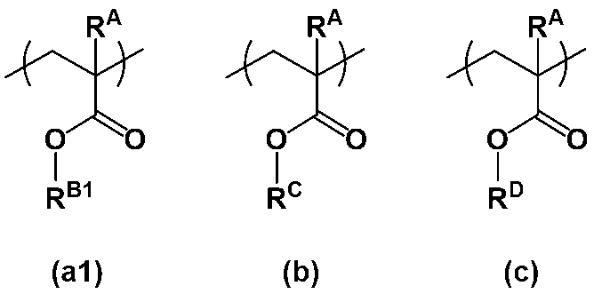
(式中、RAは、それぞれ独立して、水素原子またはメチル基であり、RB1は、少なくとも1つの水素原子がフッ素原子で置換された炭素数3または4の分岐状のアルキル基であり、RCは、ヒドロキシ基を有する炭素数1~10のアルキル基またはヒドロキシ基を有する炭素数6~20の多環式アルキル基であり、RDは、炭素数の6~20の多環式アルキル基で置換されていてもよい炭素数1~10のアルキル基、炭素数の6~20の多環式アルキル基または炭素数6~12のアリール基である。)
8. 上記(C)無電解めっき触媒層が、アルコキシ基、ヒドロキシ基、アンモニウム基、カルボキシ基またはシアノ基を有するポリマーと金属微粒子とを含有する2の積層体。
9. 上記金属微粒子が、パラジウム微粒子である8の積層体。
10. 上記ポリマーが、ハイパーブランチポリマーである8の積層体。
11. 上記ハイパーブランチポリマーが、重量平均分子量が500~5,000,000である、式[1]で表されるハイパーブランチポリマーである10の積層体。

[式中、R1は、それぞれ独立して、水素原子またはメチル基であり、
R2、R3およびR4は、それぞれ独立して、水素原子、炭素数1~20の直鎖状、分岐状もしくは環状のアルキル基、炭素数7~20のアリールアルキル基、または-(CH2CH2O)mR5(式中、R5は、水素原子またはメチル基を表し、mは、2~100の整数を表す。)であり、
上記アルキル基およびアリールアルキル基は、アルコキシ基、ヒドロキシ基、アンモニウム基、カルボキシ基またはシアノ基で置換されていてもよく、
上記R2、R3およびR4のうちの2つの基が一緒になって、直鎖状、分岐状もしくは環状のアルキレン基を表すか、またはR2、R3およびR4ならびにこれらが結合する窒素原子とともに環を形成してもよく、
X-は、陰イオンであり、
nは、2~100,000の整数であり
A1は、下記式[2]で表される構造である。

(式中、A2は、エーテル結合またはエステル結合を含んでいてもよい炭素数1~30の直鎖状、分岐状または環状のアルキレン基であり、
Y1、Y2、Y3およびY4は、それぞれ独立して、水素原子、炭素数1~20のアルキル基、炭素数1~20のアルコキシ基、ニトロ基、ヒドロキシ基、アミノ基、カルボキシル基またはシアノ基である。)]
12. 上記金属微粒子と、上記ハイパーブランチポリマーとが複合体を形成している10の積層体。
13. 上記ハイパーブランチポリマーが、重量平均分子量が500~5,000,000である、式[3]で表されるハイパーブランチポリマーである10の積層体。
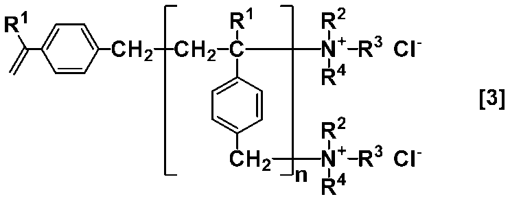
(式中、R1、R2、R3、R4およびnは、上記と同じである。)
14. (A)支持基材上に(B)有機薄膜からなる剥離層を成膜する工程、および
(B)有機薄膜からなる剥離層上に(C)無電解めっき触媒層を成膜する工程
を含む2~13のいずれかの積層体の製造方法。
15. さらに、(C)無電解めっき触媒層上に(D)無電解銅層を形成する工程を含む14の積層体の製造方法。
16. 2~13のいずれかの積層体の(D)無電解銅層を樹脂基板に圧着し、(A)支持基材を剥離して、上記(D)無電解銅層を上記樹脂基板側に転写するプリント配線基板用シード層の製造方法。
17. 2~13のいずれかの積層体の(D)無電解銅層を樹脂基板に圧着し、(A)支持基材を剥離して、上記(D)無電解銅層を上記樹脂基板に転写した後、パラジウムエッチング液で(C)無電解めっき触媒層を除去するプリント配線基板用シード層の製造方法。
18. 上記(A)支持基材を剥離する際、(B)有機薄膜からなる剥離層と(C)無電解めっき触媒層の界面で剥離する、16または17のプリント配線基板用シード層の製造方法。
19. 16または17のプリント配線基板用シード層を用いるプリント配線基板の製造方法。
1. (A)支持基材と、(B)有機薄膜からなる剥離層と、(C)無電解めっき触媒層とが順番に積層された積層体。
2. さらに、上記(C)無電解めっき触媒層の上に(D)無電解銅層が積層された1の積層体。
3. 上記(A)支持基材が、プラスチック支持基材である2の積層体。
4. 上記(B)有機薄膜からなる剥離層が、フッ素含有ポリマーおよび熱硬化性樹脂を含有する剥離層形成用組成物から得られる剥離層である2の積層体。
5. 上記熱硬化性樹脂が、ポリウレアおよび架橋剤からなる4の積層体。
6. 上記ポリウレアが、下記式(U1)で表される繰り返し単位を含む5の積層体。
Xu1は、下記式(U1-1)、(U1-2)、(U1-3)または(U1-4)で表される基であり、
Qu1は、下記式(U1-5)または(U1-6)で表される基である。
7. 上記フッ素含有ポリマーが、下記式(a1)で表される繰り返し単位、下記式(b)で表される繰り返し単位および下記式(c)で表される繰り返し単位を含むポリマーである4の積層体。
8. 上記(C)無電解めっき触媒層が、アルコキシ基、ヒドロキシ基、アンモニウム基、カルボキシ基またはシアノ基を有するポリマーと金属微粒子とを含有する2の積層体。
9. 上記金属微粒子が、パラジウム微粒子である8の積層体。
10. 上記ポリマーが、ハイパーブランチポリマーである8の積層体。
11. 上記ハイパーブランチポリマーが、重量平均分子量が500~5,000,000である、式[1]で表されるハイパーブランチポリマーである10の積層体。
R2、R3およびR4は、それぞれ独立して、水素原子、炭素数1~20の直鎖状、分岐状もしくは環状のアルキル基、炭素数7~20のアリールアルキル基、または-(CH2CH2O)mR5(式中、R5は、水素原子またはメチル基を表し、mは、2~100の整数を表す。)であり、
上記アルキル基およびアリールアルキル基は、アルコキシ基、ヒドロキシ基、アンモニウム基、カルボキシ基またはシアノ基で置換されていてもよく、
上記R2、R3およびR4のうちの2つの基が一緒になって、直鎖状、分岐状もしくは環状のアルキレン基を表すか、またはR2、R3およびR4ならびにこれらが結合する窒素原子とともに環を形成してもよく、
X-は、陰イオンであり、
nは、2~100,000の整数であり
A1は、下記式[2]で表される構造である。
Y1、Y2、Y3およびY4は、それぞれ独立して、水素原子、炭素数1~20のアルキル基、炭素数1~20のアルコキシ基、ニトロ基、ヒドロキシ基、アミノ基、カルボキシル基またはシアノ基である。)]
12. 上記金属微粒子と、上記ハイパーブランチポリマーとが複合体を形成している10の積層体。
13. 上記ハイパーブランチポリマーが、重量平均分子量が500~5,000,000である、式[3]で表されるハイパーブランチポリマーである10の積層体。
14. (A)支持基材上に(B)有機薄膜からなる剥離層を成膜する工程、および
(B)有機薄膜からなる剥離層上に(C)無電解めっき触媒層を成膜する工程
を含む2~13のいずれかの積層体の製造方法。
15. さらに、(C)無電解めっき触媒層上に(D)無電解銅層を形成する工程を含む14の積層体の製造方法。
16. 2~13のいずれかの積層体の(D)無電解銅層を樹脂基板に圧着し、(A)支持基材を剥離して、上記(D)無電解銅層を上記樹脂基板側に転写するプリント配線基板用シード層の製造方法。
17. 2~13のいずれかの積層体の(D)無電解銅層を樹脂基板に圧着し、(A)支持基材を剥離して、上記(D)無電解銅層を上記樹脂基板に転写した後、パラジウムエッチング液で(C)無電解めっき触媒層を除去するプリント配線基板用シード層の製造方法。
18. 上記(A)支持基材を剥離する際、(B)有機薄膜からなる剥離層と(C)無電解めっき触媒層の界面で剥離する、16または17のプリント配線基板用シード層の製造方法。
19. 16または17のプリント配線基板用シード層を用いるプリント配線基板の製造方法。
本発明の積層体は、剥離層にクロムを含有せず、さらに無電解めっき処理の適用により、薄い無電解銅層を形成できるため、環境負荷を低減しながら、ファインパターンの形成に適した無電解銅層積層体を製造することができる。
そして、上記剥離層は、無電解めっき触媒層との界面で容易に剥離するものであるので、プレス加工時に、薄い無電解銅層をシワ等が発生することなくプリント配線基板の樹脂基板側に転写することができるものである。その結果、ファインパターンの形成に適したプリント配線基板用シード層を再現性よく得ることができるようになる。
さらに、得られるプリント配線基板用シード層は、無電解銅層が薄く形成されているため、銅の使用量を削減できることに加え、プリント配線基板の配線形成工程において、フラッシュエッチング時のサイドエッチが低減され、その結果、配線をより微細化することができるようになる。
また、プラスチック支持基材を用いることで、従来の銅板を支持基材に用いた場合と比較して、無電解銅層の平滑性は格段に向上することから、高周波帯で伝送損失の小さいプリント配線基板を形成することができる。
そして、上記剥離層は、無電解めっき触媒層との界面で容易に剥離するものであるので、プレス加工時に、薄い無電解銅層をシワ等が発生することなくプリント配線基板の樹脂基板側に転写することができるものである。その結果、ファインパターンの形成に適したプリント配線基板用シード層を再現性よく得ることができるようになる。
さらに、得られるプリント配線基板用シード層は、無電解銅層が薄く形成されているため、銅の使用量を削減できることに加え、プリント配線基板の配線形成工程において、フラッシュエッチング時のサイドエッチが低減され、その結果、配線をより微細化することができるようになる。
また、プラスチック支持基材を用いることで、従来の銅板を支持基材に用いた場合と比較して、無電解銅層の平滑性は格段に向上することから、高周波帯で伝送損失の小さいプリント配線基板を形成することができる。
以下、本発明についてさらに詳しく説明する。
図1に本発明の積層体の断面構造の一例を示す。本発明の積層体10は、図1に示したように、(A)支持基材11と、(B)有機薄膜からなる剥離層12と、(C)無電解めっき触媒層13とが順番に積層されたものである。
また、上記積層体10を用いることで、(A)支持基材11と、(B)有機薄膜からなる剥離層12と、(C)無電解めっき触媒層13と、(D)無電解銅層14とが順番に積層された積層体1(以下「無電解銅層積層体1」と表記することもある。)も提供することができる(図2参照)。
図1に本発明の積層体の断面構造の一例を示す。本発明の積層体10は、図1に示したように、(A)支持基材11と、(B)有機薄膜からなる剥離層12と、(C)無電解めっき触媒層13とが順番に積層されたものである。
また、上記積層体10を用いることで、(A)支持基材11と、(B)有機薄膜からなる剥離層12と、(C)無電解めっき触媒層13と、(D)無電解銅層14とが順番に積層された積層体1(以下「無電解銅層積層体1」と表記することもある。)も提供することができる(図2参照)。
(A)支持基材11
支持基材11は、公知の材料から適宜選択して用いることができ、特に限定されるものではないが、その具体例としては、銅、アルミニウム、鉄、金、銀、ニッケル、パラジウム、モリブデンまたはこれらの合金の箔等の金属箔;ポリイミド、ポリエーテルイミド、ポリアミドイミド、ポリエチレンテレフタレート(PET)、ポリエチレンナフタレート、ポリカーボネート、ポリフェニレンエーテル、ポリフェニレンサルファイド、ポリエーテルエーテルケトン等のプラスチック支持基材等が挙げられる。本発明では、金属使用量の低減や、軽量化や平坦性の向上が期待でき、酸化による経時劣化がない点から、プラスチック支持基材が好ましく、さらに耐熱性を考慮すると、ポリイミドまたはポリエチレンテレフタレートがより好ましい。
支持基材11は、公知の材料から適宜選択して用いることができ、特に限定されるものではないが、その具体例としては、銅、アルミニウム、鉄、金、銀、ニッケル、パラジウム、モリブデンまたはこれらの合金の箔等の金属箔;ポリイミド、ポリエーテルイミド、ポリアミドイミド、ポリエチレンテレフタレート(PET)、ポリエチレンナフタレート、ポリカーボネート、ポリフェニレンエーテル、ポリフェニレンサルファイド、ポリエーテルエーテルケトン等のプラスチック支持基材等が挙げられる。本発明では、金属使用量の低減や、軽量化や平坦性の向上が期待でき、酸化による経時劣化がない点から、プラスチック支持基材が好ましく、さらに耐熱性を考慮すると、ポリイミドまたはポリエチレンテレフタレートがより好ましい。
上記支持基材11の厚さについて特に制限はないが、支持基材としての役目を果たす上で適した厚さに適宜調節すればよく、一般的には5~100μmである。重量の削減や原料コストの低減という観点からはプラスチック支持基材の厚みは小さいことが好ましく、プラスチック支持基材の厚みが小さすぎるとキャリア付き極薄銅箔のハンドリング性が低下する。そのため、キャリアの厚みは、好ましくは5~100μmであり、より好ましくは10~50μmである。
上記支持基材11としては、市販品を用いることができ、例えば、ポリイミドの市販品として、東レ(株)製のポリイミドフィルムの「カプトン(登録商標)」シリーズ等が挙げられる。また、ポリエチレンテレフタレートの市販品として、東洋紡(株)製のポリエチレンテレフタレートフィルムの「コスモシャイン(登録商標)」シリーズ、帝人(株)製の「テトロン(登録商標)」(現:東洋紡(株)製の「東洋紡エステル(登録商標)フィルム」)シリーズ、東レ(株)製のポリエチレンテレフタレートフィルムの「ルミラー」シリーズ等が挙げられる。
(B)有機薄膜からなる剥離層12
有機薄膜からなる剥離層(以下、単に「剥離層」と表記することもある。)12は、支持基材11との優れた密着性および無電解めっき触媒層13との適度な密着性と適度な剥離性とを有する層であり、無電解めっき処理により形成された無電解銅層14を支持基材11上に適切に固定するとともに、プレス加工時において、無電解銅層14を無電解めっき触媒層13とともに上記支持基材11から剥離させるための層である。
そして、上記剥離層12は有機薄膜からなり、従来、剥離層の形成に用いられてきたクロムを含むものではないので、環境負荷の低減が期待される。
有機薄膜からなる剥離層(以下、単に「剥離層」と表記することもある。)12は、支持基材11との優れた密着性および無電解めっき触媒層13との適度な密着性と適度な剥離性とを有する層であり、無電解めっき処理により形成された無電解銅層14を支持基材11上に適切に固定するとともに、プレス加工時において、無電解銅層14を無電解めっき触媒層13とともに上記支持基材11から剥離させるための層である。
そして、上記剥離層12は有機薄膜からなり、従来、剥離層の形成に用いられてきたクロムを含むものではないので、環境負荷の低減が期待される。
上記剥離層12は、熱硬化性樹脂およびフッ素含有ポリマーを含有する剥離層形成用組成物から得られるものが好ましい。
[熱硬化性樹脂]
上記熱硬化性樹脂としては、ポリウレア樹脂、ポリアクリル樹脂、ポリイミド樹脂、メラミン樹脂、エポキシ樹脂、フェノール樹脂、不飽和ポリエステル樹脂、ビニルエステル樹脂、ポリウレタン樹脂、シリコーン樹脂等が挙げられるが、ポリウレア樹脂が好ましい。
上記熱硬化性樹脂としては、ポリウレア樹脂、ポリアクリル樹脂、ポリイミド樹脂、メラミン樹脂、エポキシ樹脂、フェノール樹脂、不飽和ポリエステル樹脂、ビニルエステル樹脂、ポリウレタン樹脂、シリコーン樹脂等が挙げられるが、ポリウレア樹脂が好ましい。
上記ポリウレア樹脂は、ポリウレアと架橋剤を原料とするものであるが、本発明では、耐熱性に優れる点から、上記ポリウレアとしては、下記式(U1)で表される繰り返し単位を含むものが好ましい。

式(1)中、Au1、Au2、Au3、Au4、Au5およびAu6は、それぞれ独立して、水素原子、メチル基またはエチル基であるが、剥離性と生産性の観点から、Au1~Au6が全て水素原子であることが好ましい。
式(1)中、Xu1は、下記式(U1-1)、(U1-2)、(U1-3)または(U1-4)で表される基である。
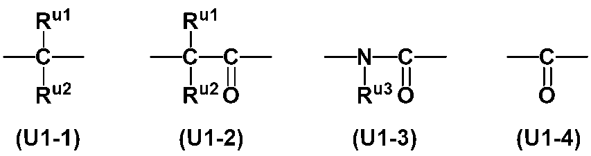
式(U1-1)および(U1-2)中、Ru1およびRu2は、それぞれ独立して、水素原子、炭素数1~6のアルキル基、炭素数3~6のアルケニル基、ベンジル基またはフェニル基であり、上記フェニル基は、炭素数1~6のアルキル基、ハロゲン原子、炭素数1~6のアルコキシ基、ニトロ基、シアノ基、ヒドロキシ基および炭素数1~6のアルキルチオ基からなる群から選ばれる少なくとも1種の基で置換されていてもよく、また、Ru1およびRu2は、互いに結合してこれらが結合する炭素原子と共に炭素数3~6の環を形成してもよい。
式(U1-3)中、Ru3は、炭素数1~6のアルキル基、炭素数3~6のアルケニル基、ベンジル基またはフェニル基であり、上記フェニル基は、炭素数1~6のアルキル基、ハロゲン原子、炭素数1~6のアルコキシ基、ニトロ基、シアノ基、ヒドロキシ基および炭素数1~6のアルキルチオ基からなる群から選ばれる少なくとも1種の基で置換されていてもよい。
Qu1は、下記式(U1-5)または(U1-6)で表される基である。
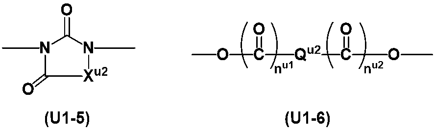
式(U1-5)中、Xu2は、式(U1-1)、式(U1-2)または式(U1-4)で表される基である。nu1およびnu2は、それぞれ独立して、0または1である。
上記式(U1-5)において、例えば、Xu2が式(U1-2)で表される基の場合、その構造は式(U1-5-1)となる。
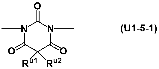
式(U1-6)中、Qu2は、炭素数1~10のアルキレン基、フェニレン基、ナフチレン基またはアントリレン基である。上記フェニレン基、ナフチレン基およびアントリレン基は、炭素数1~6のアルキル基、ハロゲン原子、炭素数1~6のアルコキシ基、ニトロ基、シアノ基、ヒドロキシ基、および炭素数1~6のアルキルチオ基からなる群から選ばれる少なくとも1種の基で置換されていてもよい。また、Qu2がフェニレン基、ナフチレン基またはアントリレン基である場合、それらの結合の位置は特に限定されない。すなわち、例えば、フェニレン基が1位と2位とで結合している場合、1位と3位とで結合している場合または1位と4位とで結合している場合、ナフチレン基が1位と2位で結合している場合、1位と4位で結合している場合、1位と5位で結合している場合または2位と3位で結合している場合、アントリレン基が1位と2位で結合している場合、1位と4位で結合している場合または9位と10位で結合している場合等がありえるが、いずれであってもよい。
上記炭素数1~6のアルキル基としては、直鎖状、分岐状、環状のいずれでもよく、例えば、メチル基、エチル基、イソプロピル基、n-ブチル基、シクロヘキシル基等が挙げられる。上記炭素数3~6のアルケニル基としては、直鎖状、分岐状、環状のいずれでもよく、例えば、2-プロペニル基、3-ブテニル基等が挙げられる。
上記炭素数1~6のアルコキシ基としては、直鎖状、分岐状、環状のいずれでもよく、例えば、メトキシ基、エトキシ基、イソプロポキシ基、n-ペンチルオキシ基およびシクロヘキシルオキシ基等が挙げられる。炭素数1~6のアルキルチオ基としては、直鎖状、分岐状、環状のいずれでもよく、例えば、メチルチオ基、エチルチオ基、イソプロピルチオ基、n-ペンチルチオ基、シクロヘキシルチオ基等が挙げられる。上記ハロゲン原子としては、フッ素原子、塩素原子、臭素原子、ヨウ素原子等が挙げられる。また、Ru1とRu2が結合して形成される炭素数3~6の環としては、シクロブタン環、シクロペンタン環、シクロヘキサン環等が挙げられる。
上記炭素数1~10のアルキレン基としては、直鎖状、分岐状、環状のいずれでもよく、例えば、メチレン基、エチレン基、プロピレン基、ペンタメチレン基、シクロヘキシレン基、2-メチルプロピレン基等が挙げられる。
なお、式(U1)において、Xu1が式(U1-2)で表される基の場合、その構造は下記式(U2)で表されるものとなり、Xu1が式(U1-3)で表される基の場合、その構造は下記式(U3)で表されるものとなる。また、式(U3)において、Ru3が、2-プロペニル基であるものが好ましい。

式(U1)中、Qu1は、(A)成分のポリウレアの耐熱性の観点から、環状構造を含んでいることが好ましい。すなわち、Qu1が、式(U1-5)で表される基、または式(U1-6)で表される基であってQu2が環状アルキレン基、フェニレン基、ナフチレン基またはアントリレン基であることが好ましく、式(U1-5)で表される基であることがより好ましい。
式(U1)で表される繰り返し単位としては、下記式(U4)~(U22)で表されるものが好ましい。なお、下記式中、Meはメチル基であり、Etはエチル基である。
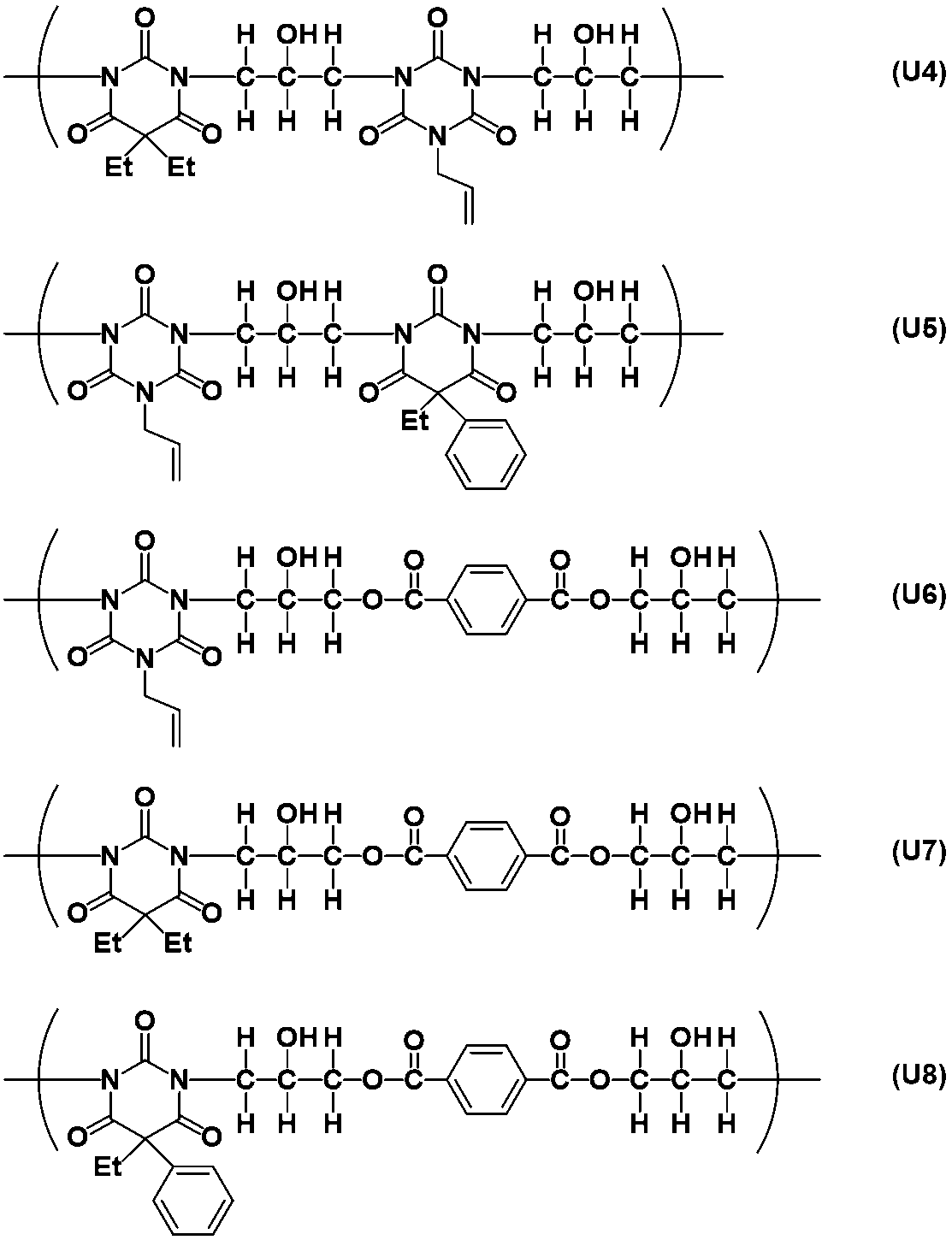
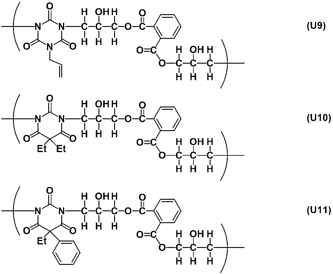


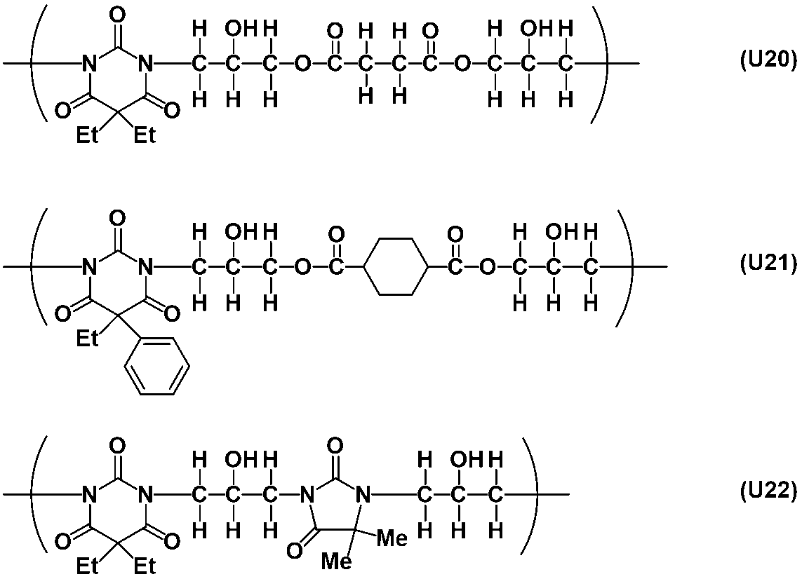
上記ポリウレアは、例えば、国際公開第2005/098542号を参考にして合成することができる。
上記ポリウレアの重量平均分子量(Mw)は、1,000~200,000が好ましく、3,000~100,000がより好ましく、4,000~30,000がより一層好ましく、5,000~20,000が更に好ましい。また、その分散度(Mw/Mn)は、1.3~4.0が好ましく、1.4~2.5がより好ましい。なお、Mnは数平均分子量であり、MwおよびMnはゲルパーミエーションクロマトグラフィー(GPC)によるポリスチレン換算測定値である
上記架橋剤としては、公知のものを用いることができ、特に限定されるものではない。本発明では、反応速度の観点から、ヒドロキシアルキル基および/またはアルコキシメチル基で置換された窒素原子を有する化合物から選択されるものが好適である。
上記架橋剤としては、下記式(C-1)~(C-5)のいずれかで表される化合物が好ましい。

式中、R11~R26は、それぞれ独立に、水素原子または炭素数1~6のアルキル基であるが、炭素数1~6のアルキル基が好ましい。R27は、水素原子またはメチル基である。
上記架橋剤として具体的には、ヘキサメチロールメラミン、テトラメチロールベンゾグアナミン、1,3,4,6-テトラメチロールグリコールウリル、ヘキサメトキシメチルメラミン、テトラメトキシメチルベンゾグアナミン、1,3,4,6-テトラキス(メトキシメチル)グリコールウリル、1,3,4,6-テトラキス(ブトキシメチル)グリコールウリル、1,3,4,6-テトラキス(ヒドロキシメチル)グリコールウリル等の含窒素化合物が挙げられる。
また、オルネクス社製メトキシメチルタイプメラミン化合物(商品名サイメル(登録商標)300、サイメル301、サイメル303、サイメル350)、ブトキシメチルタイプメラミン化合物(商品名マイコート(登録商標)506、マイコート508)、グリコールウリル化合物(商品名サイメル1170、POWDERLINK 1174)、メチル化尿素樹脂(商品名UFR65)、ブチル化尿素樹脂(商品名UFR300、U-VAN10S60、U-VAN10R、U-VAN11HV)、DIC(株)製尿素/ホルムアルデヒド系樹脂(商品名ベッカミン(登録商標)J-300S、ベッカミンP-955、ベッカミンN)等の市販されている含窒素化合物を挙げることができる。
また、架橋剤として、N-ヒドロキシメチル(メタ)アクリルアミド、N-メトキシメチル(メタ)アクリルアミド、N-エトキシメチル(メタ)アクリルアミド、N-ブトキシメチル(メタ)アクリルアミド等のヒドロキシメチル基またはアルコキシメチル基で置換された(メタ)アクリルアミド化合物を使用して製造されるポリマーを用いることができる。そのようなポリマーとしては、例えば、ポリ(N-ブトキシメチル(メタ)アクリルアミド)、N-ブトキシメチル(メタ)アクリルアミドとスチレンとの共重合体、N-ヒドロキシメチル(メタ)アクリルアミドとメチル(メタ)アクリレートとの共重合体、N-エトキシメチルメタクリルアミドとベンジルメタクリレートの共重合体、N-ブトキシメチル(メタ)アクリルアミドとベンジル(メタ)アクリレートと2-ヒドロキシプロピル(メタ)アクリレートとの共重合体等が挙げられる。
上記架橋剤としてより好ましくは、ヘキサメトキシメチルメラミン、テトラメトキシメチルベンゾグアナミン、1,3,4,6-テトラキス(メトキシメチル)グリコールウリル(POWDERLINK 1174)、1,3,4,6-テトラキス(ブトキシメチル)グリコールウリル、1,3,4,6-テトラキス(ヒドロキシメチル)グリコールウリルが挙げられる。
これら架橋剤は、自己縮合による架橋反応を起こすことができる。また、上記ポリウレア中のヒドロキシ基と架橋反応を起こすことができる。そして、このような架橋反応によって、形成される剥離層12は強固になり、有機溶剤に対する溶解性が低いものとなる。
架橋剤の含有量は、上記ポリウレア100質量部に対し、10~100質量部が好ましく、20~50質量部がより好ましい。架橋剤の含有量が上記範囲であれば、適度な剥離性を有し、製膜後の安定性に優れる剥離層12を与え得る組成物が得られる。上記架橋剤は、1種単独で使用してもよく、2種以上を組み合わせて使用してもよい。
[フッ素含有ポリマー]
フッ素含有ポリマーとしては、公知のものを用いることができ、特に限定されるものではない。具体例としては、国際公開第2020/158521号や国際公開第2021/132383号に記載されたフッ素ポリマーが挙げられるが、本発明では、下記式(a1)で表される繰り返し単位、下記式(b)で表される繰り返し単位および下記式(c)で表される繰り返し単位を含むポリマーが好ましい。
フッ素含有ポリマーとしては、公知のものを用いることができ、特に限定されるものではない。具体例としては、国際公開第2020/158521号や国際公開第2021/132383号に記載されたフッ素ポリマーが挙げられるが、本発明では、下記式(a1)で表される繰り返し単位、下記式(b)で表される繰り返し単位および下記式(c)で表される繰り返し単位を含むポリマーが好ましい。

式中、RAは、それぞれ独立して、水素原子またはメチル基である。RB1は、少なくとも1つの水素原子がフッ素原子で置換された炭素数3または4の分岐状のアルキル基である。RCは、ヒドロキシ基を有する炭素数1~10のアルキル基またはヒドロキシ基を有する炭素数6~20の多環式アルキル基である。RDは、炭素数の6~20の多環式アルキル基で置換されていてもよい炭素数1~10のアルキル基、炭素数の6~20の多環式アルキル基または炭素数の6~12のアリール基である。
上記炭素数3または4の分岐状アルキル基としては、イソプロピル基、イソブチル基、sec-ブチル基およびtert-ブチル基が挙げられる。RB1としては、これらの分岐状アルキル基の少なくとも1つの水素原子がフッ素原子で置換されたものが好ましく、具体例としては、1,1,1-トリフルオロイソプロピル基、1,1,1,3,3,3-ヘキサフルオロイソプロピル基、ノナフルオロtert-ブチル基等が挙げられる。
上記ヒドロキシ基を有する炭素数1~10のアルキル基としては、ヒドロキシメチル基、2-ヒドロキシエチル基、3-ヒドロキシプロピル基、4-ヒドロキシブチル基、5-ヒドロキシペンチル基、6-ヒドロキシヘキシル基、7-ヒドロキシヘプチル基、8-ヒドロキシオクチル基、9-ヒドロキシノニル基、10-ヒドロキシデシル基、2-ヒドロキシ-1-メチルエチル基、2-ヒドロキシ-1,1-ジメチルエチル基、3-ヒドロキシ-1-メチルプロピル基、3-ヒドロキシ-2-メチルプロピル基、3-ヒドロキシ-1,1-ジメチルプロピル基、3-ヒドロキシ-1,2-ジメチルプロピル基、3-ヒドロキシ-2,2-ジメチルプロピル基、4-ヒドロキシ-1-メチルブチル基、4-ヒドロキシ-2-メチルブチル基、4-ヒドロキシ-3-メチルブチル基等の炭素数2~10のヒドロキシアルキル基であって、ヒドロキシ基が結合する炭素原子が第1級炭素原子であるもの;1-ヒドロキシエチル基、1-ヒドロキシプロピル基、2-ヒドロキシプロピル基、1-ヒドロキシブチル基、2-ヒドロキシブチル基、1-ヒドロキシヘキシル基、2-ヒドロキシヘキシル基、1-ヒドロキシオクチル基、2-ヒドロキシオクチル基、1-ヒドロキシデシル基、2-ヒドロキシデシル基、1-ヒドロキシ-1-メチルエチル基、2-ヒドロキシ-2-メチルプロピル基等の炭素数1~10のヒドロキシアルキル基であって、ヒドロキシ基が結合する炭素原子が第2級または第3級炭素原子であるものが挙げられる。
上記炭素数6~20の多環式アルキル基としては、1-アダマンチル基、2-アダマンチル基、イソボルニル基、ノルボルニル基等が挙げられる。上記炭素数6~12のアリール基としては、フェニル基、1-ナフチル基、2-ナフチル基、1-ビフェニル基、2-ビフェニル基等が挙げられる。
上記ヒドロキシ基を有する炭素数6~20の多環式アルキル基としては、3-ヒドロキシ-1-アダマンチル基、4-ヒドロキシ-1-アダマンチル基、5-ヒドロキシ-1-アダマンチル基、3-ヒドロキシ-2-アダマンチル基、4-ヒドロキシ-2-アダマンチル基、5-ヒドロキシ-2-アダマンチル基、ヒドロキシノルボルニル基、上記ヒドロキシ基を有する炭素数6~12のアリール基としては、4-ヒドロキシフェニル基、3-ヒドロキシフェニル基等が挙げられる。
また、上記フッ素含有ポリマーは、下記式(a2)で表される繰り返し単位、下記式(b)で表される繰り返し単位、下記式(c)で表される繰り返し単位および下記式(d)で表される繰り返し単位を含むものであってもよい。

式中、RA、RCおよびRDは、上記と同じ。RB2は、少なくとも1つの水素原子がフッ素原子で置換された炭素数3または4の分岐状のアルキル基である(ただし、2-メチル-1,1,1,3,3,3-ヘキサフルオロイソプロピル基を除く。)。上記炭素数3又は4の分岐状のアルキル基としては、前述したものと同様のものが挙げられる。REは、単結合、炭素数6~20の多環式アルキレン基又は炭素数6~12のアリーレン基である。RFは、単結合または炭素数1~10のアルキレン基である。RGは、メチル基、エチル基またはヒドロキシ基である。
上記炭素数6~20の多環式アルキレン基としては、前述した炭素数6~20の多環式アルキル基の具体例から水素原子を1つ除いた基が挙げられ、例えば、アダマンチレン基、イソボルニレン基、ノルボルニレン基等が挙げられる。
上記炭素数6~12のアリーレン基としては、前述した炭素数6~12のアリール基の具体例から水素原子を1つ除いた基が挙げられ、例えば、フェニレン基、ナフチレン基、ビフェニリレン基等が挙げられる。
上記炭素数1~10のアルキレン基としては、上記Qu2の説明において例示したものと同様のものを挙げることができる。本発明では、炭素数1~5のアルキレン基が好ましく、メチレン基およびエチレン基がより好ましく、メチレン基がより一層好ましい。
式(a1)または(a2)で表される繰り返し単位としては、下記式(a-1)~(a-3)で表されるものが挙げられるが、これらに限定されない。なお、下記式中、RAは、上記と同じである。
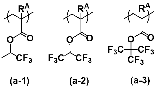
式(b)で表される繰り返し単位としては、下記式(b-1)~(b-17)で表されるものが挙げられるが、これらに限定されない。なお、下記式中、RAは、上記と同じである。
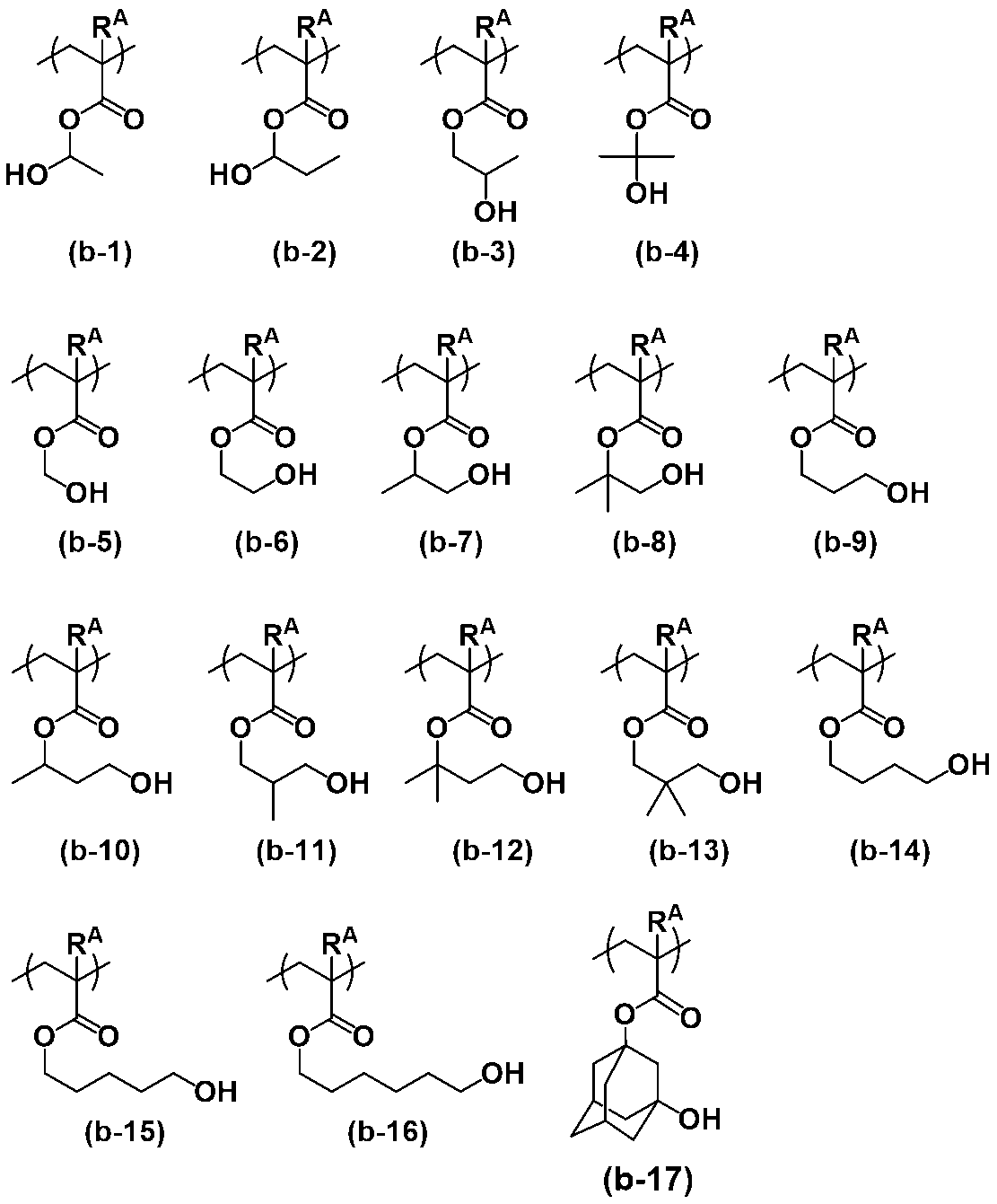
式(c)で表される繰り返し単位としては、下記式(c-1)~(c-15)で表されるものが挙げられるが、これらに限定されない。なお、下記式中、RAは、上記と同じである。

式(d)で表される繰り返し単位としては、下記式(d-1)~(d-8)で表されるものが挙げられるが、これらに限定されない。なお、下記式中、RAは、上記と同じである。
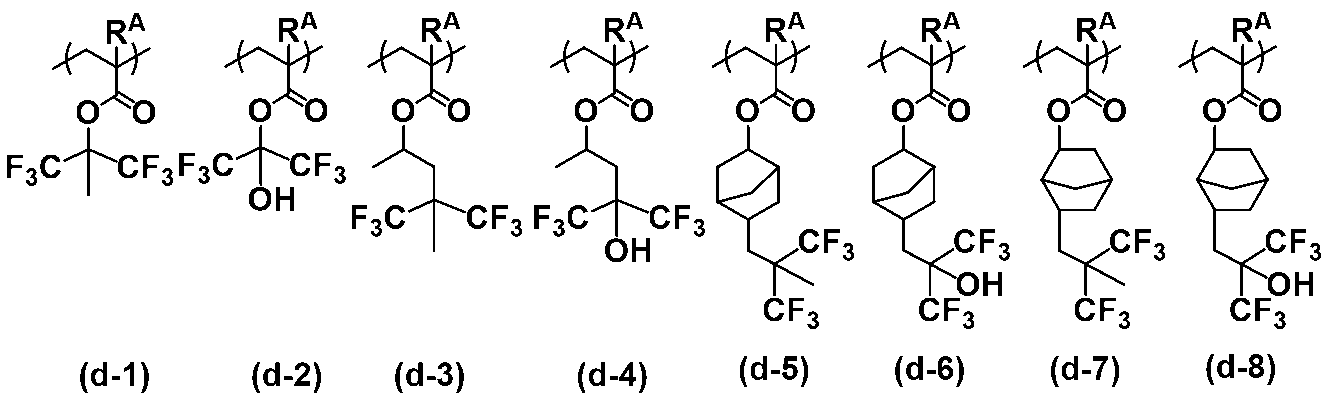
フッ素含有ポリマーが、式(a1)で表される繰り返し単位、式(b)で表される繰り返し単位および式(c)で表される繰り返し単位を含むものであって、式(b)で表される繰り返し単位中のヒドロキシアルキル基においてヒドロキシ基が結合する炭素原子が第2級または第3級炭素原子である場合(以下、このようなフッ素含有ポリマーをフッ素含有ポリマーD1という。)、式(a1)で表される繰り返し単位の含有率は、全繰り返し単位中、30~60モル%が好ましく、35~50モル%がより好ましい。式(b)で表される繰り返し単位の含有率は、全繰り返し単位中、10~35モル%が好ましく、15~30モル%がより好ましい。式(c)で表される繰り返し単位の含有率は、全繰り返し単位中、5~60モル%が好ましく、20~50モル%がより好ましい。
上記フッ素含有ポリマーが、式(a1)で表される繰り返し単位、式(b)で表される繰り返し単位および式(c)で表される繰り返し単位を含むものであって、式(b)で表される繰り返し単位中のヒドロキシアルキル基においてヒドロキシ基が結合する炭素原子が第1級炭素原子である場合(以下、このようなフッ素含有ポリマーをフッ素含有ポリマーD2という。)、式(a1)で表される繰り返し単位の含有率は、全繰り返し単位中、15~60モル%が好ましく、25~60モル%がより好ましく、30~60モル%がより一層好ましく、35~50モル%が更に好ましい。式(b)で表される繰り返し単位の含有率は、全繰り返し単位中、8~38モル%が好ましく、10~38モル%が好ましく、10~35モル%がより好ましく、15~30モル%がより一層好ましい。式(c)で表される繰り返し単位の含有率は、全繰り返し単位中、2~77モル%が好ましく、2~65モル%がより好ましく、5~60モル%がより一層好ましく、20~50モル%が更に好ましい。
上記フッ素含有ポリマーが、式(a2)で表される繰り返し単位、式(b)で表される繰り返し単位、式(c)で表される繰り返し単位および式(d)で表される繰り返し単位を含むものである場合(以下、このようなフッ素含有ポリマーをフッ素含有ポリマーD3という。)、式(a2)で表される繰り返し単位の含有率は、全繰り返し単位中、2~45モル%が好ましく、5~35モル%がより好ましい。式(b)で表される繰り返し単位の含有率は、全繰り返し単位中、20~35モル%が好ましく、25~35モル%がより好ましい。式(c)で表される繰り返し単位の含有率は、全繰り返し単位中、30~45モル%が好ましく、35~45モル%がより好ましい。式(d)で表される繰り返し単位の含有率は、全繰り返し単位中、5~18モル%が好ましく、5~15モル%がより好ましい。
上記フッ素含有ポリマーのMwは、2,000~10,000が好ましく、3,000~6,000がより好ましい。また、そのMw/Mnは、1.0~2.1が好ましく、1.0~1.9がより好ましい。
上記フッ素含有ポリマーの含有量は、上記ポリウレア100質量部に対し、5~100質量部である。フッ素含有ポリマーの含有量を上記範囲とすることで、良好な塗布性と適度な剥離性が得られる。
ここで、フッ素含有ポリマーが、フッ素含有ポリマーD1である場合、その含有量は、上記ポリウレア100質量部に対し、10~100質量部が好ましく、20~100質量部がより好ましく、30~100質量部がより一層好ましい。また、上記フッ素含有ポリマーが、フッ素含有ポリマーD1以外のものである場合、その含有量は、上記ポリウレア100質量部に対し、5~80質量部が好ましく、5~50質量部がより好ましい。
上記フッ素含有ポリマーは、1種単独で使用してもよく、2種以上を組み合わせて使用してもよい。
[酸化合物またはその塩]
本発明の剥離層形成用組成物は、酸化合物またはその塩を含んでいてもよい。
酸化合物としては、p-トルエンスルホン酸、トリフルオロメタンスルホン酸、ピリジニウム-p-トルエンスルホネート、サリチル酸、カンファースルホン酸、スルホサリチル酸、4-クロロベンゼンスルホン酸、4-ヒドロキシベンゼンスルホン酸、ベンゼンジスルホン酸、ドデシルベンゼンスルホン酸、1-ナフタレンスルホン酸およびピリジニウム-1-ナフタレンスルホン酸等のスルホン酸化合物や、サリチル酸、スルホサリチル酸、クエン酸、安息香酸、ヒドロキシ安息香酸等のカルボン酸化合物が挙げられる。また、上記酸化合物の塩としては、上記酸のピリジニウム塩、イソプロパノールアミン塩、N-メチルモルホリン塩等が挙げられ、具体的には、p-トルエンスルホン酸ピリジニウム、1-ナフタレンスルホン酸ピリジニウム、イソプロパノールアミンp-トルエンスルホン酸塩、N-メチルモルホリンp-トルエンスルホン酸塩等が挙げられる。
本発明の剥離層形成用組成物は、酸化合物またはその塩を含んでいてもよい。
酸化合物としては、p-トルエンスルホン酸、トリフルオロメタンスルホン酸、ピリジニウム-p-トルエンスルホネート、サリチル酸、カンファースルホン酸、スルホサリチル酸、4-クロロベンゼンスルホン酸、4-ヒドロキシベンゼンスルホン酸、ベンゼンジスルホン酸、ドデシルベンゼンスルホン酸、1-ナフタレンスルホン酸およびピリジニウム-1-ナフタレンスルホン酸等のスルホン酸化合物や、サリチル酸、スルホサリチル酸、クエン酸、安息香酸、ヒドロキシ安息香酸等のカルボン酸化合物が挙げられる。また、上記酸化合物の塩としては、上記酸のピリジニウム塩、イソプロパノールアミン塩、N-メチルモルホリン塩等が挙げられ、具体的には、p-トルエンスルホン酸ピリジニウム、1-ナフタレンスルホン酸ピリジニウム、イソプロパノールアミンp-トルエンスルホン酸塩、N-メチルモルホリンp-トルエンスルホン酸塩等が挙げられる。
上記剥離層形成用組成物が酸化合物またはその塩を含む場合、その含有量は、上記ポリウレア100質量部に対し、0.01~15質量部が好ましく、0.1~10質量部がより好ましい。酸化合物またはその塩の含有量が上記範囲であれば、高い耐熱性と適度な剥離性とを有し、製膜後の安定性に優れる剥離層12を与え得る組成物が得られる。酸化合物またはその塩は、1種単独で使用してもよく、2種以上を組み合わせて使用してもよい。
[溶剤]
上記剥離層形成用組成物は、溶剤を含んでいてもよい。
溶剤としては、上述した各成分および後述するその他の添加剤を溶解できるものであれば、その種類および構造等は特に限定されるものでないが、本発明では、炭素数3~20のグリコールエーテル系溶剤、炭素数3~20のエステル系溶剤、炭素数3~20のケトン系溶剤、または炭素数3~20の環状化合物系溶剤が好ましい。
上記剥離層形成用組成物は、溶剤を含んでいてもよい。
溶剤としては、上述した各成分および後述するその他の添加剤を溶解できるものであれば、その種類および構造等は特に限定されるものでないが、本発明では、炭素数3~20のグリコールエーテル系溶剤、炭素数3~20のエステル系溶剤、炭素数3~20のケトン系溶剤、または炭素数3~20の環状化合物系溶剤が好ましい。
上記グリコールエーテル系溶剤としては、プロピレングリコールモノメチルエーテル(PGME)、プロピレングリコールモノメチルエーテルアセテート(PGMEA)、プロピレングリコールモノエチルエーテル、プロピレングリコールモノエチルエーテルアセテート、プロピレングリコールモノプロピルエーテル、プロピレングリコールモノブチルエーテル、エチレングリコールモノメチルエーテル、エチレングリコールジメチルエーテル、エチレングリコールジエチルエーテル、エチレングリコールモノメチルエーテルアセテート、ジエチレングリコールモノメチルエーテル、ジエチレングリコールモノエチルエーテル、ジエチレングリコールジメチルエーテル(Diglyme)、ジエチレングリコールジエチルエーテル、ジエチレングリコールモノヘキシルエーテル、ジエチレングリコールブチルメチルエーテル、トリエチレングリコールモノメチルエーテル、トリエチレングリコールジメチルエーテル(Triglyme)、ジエチレングリコールモノブチルエーテル、ジエチレングリコールエチルメチルエーテル、ジエチレングリコールイソプロピルメチルエーテル、ジエチレングリコールジブチルエーテル、ジメトキシテトラエチレングリコール、ジプロピレングリコールメチルエーテル、ジプロピレングリコールジメチルエーテル、ジプロピレングリコールモノメチルエーテル、ジエチレングリコールモノエチルエーテルアセタート(DEGEEA)、メトキシメチルブタノール、トリプロピレングリコールジメチルエーテル、トリエチレングリコールブチルメチルエーテル等が挙げられる。
上記エステル系溶剤としては、酢酸エチル、酢酸プロピル、酢酸ブチル、酢酸イソブチル、乳酸エチル、γ-ブチロラクトン、2-ヒドロシキイソ酪酸メチル、2-ヒドロシキイソ酪酸エチル、メトキシプロピオン酸メチル、エトキシプロピオン酸エチル等が挙げられる。
上記ケトン系溶剤としては、メチルエチルケトン、シクロヘキサノン、シクロペンタノン、ベンゾフェノン等が挙げられる。
上記環状化合物溶剤としては、N-メチルピロリドン、γ-ブチロラクトン等が挙げられる。
上記剥離層形成用組成物が溶剤を含む場合、その含有量は、本発明の剥離層形成用組成物中の固形分濃度が、0.1~40質量%となる量が好ましく、0.5~20質量%となる量がより好ましく、0.5~10質量%となる量がより一層好ましい。なお、固形分とは、剥離層形成用組成物の全成分のうち、溶剤以外のものの総称である。上記溶剤は、1種単独で使用してもよく、2種以上を混合して使用してもよい。
[その他の添加剤]
上記剥離層形成用組成物は、必要に応じて界面活性剤を含んでもよい。界面活性剤を添加することで、基板に対する前記剥離層形成用組成物の塗布性を向上させることができる。上記界面活性剤としては、ノニオン系界面活性剤、フッ素系界面活性剤、シリコーン系界面活性剤等の公知の界面活性剤を用いることができる。
上記剥離層形成用組成物は、必要に応じて界面活性剤を含んでもよい。界面活性剤を添加することで、基板に対する前記剥離層形成用組成物の塗布性を向上させることができる。上記界面活性剤としては、ノニオン系界面活性剤、フッ素系界面活性剤、シリコーン系界面活性剤等の公知の界面活性剤を用いることができる。
上記ノニオン系界面活性剤の具体例としては、例えば、ポリオキシエチレンラウリルエーテル、ポリオキシエチレンステアリルエーテル、ポリオキシエチレンセチルエーテル、ポリオキシエチレンオレイルエーテル等のポリオキシエチレンアルキルエーテル類;ポリオキシエチレンオクチルフェニルエーテル、ポリオキシエチレンノニルフェニルエーテル等のポリオキシエチレンアルキルアリールエーテル類;ポリオキシエチレン・ポリオキシプロピレンブロックコポリマー類;ソルビタンモノラウレート、ソルビタンモノパルミテート、ソルビタンモノステアレート、ソルビタンモノオレエート、ソルビタントリオレエート、ソルビタントリステアレート等のソルビタン脂肪酸エステル類;ポリオキシエチレンソルビタンモノラウレート、ポリオキシエチレンソルビタンモノパルミテート、ポリオキシエチレンソルビタンモノステアレート、ポリオキシエチレンソルビタントリオレエート、ポリオキシエチレンソルビタントリステアレート等のポリオキシエチレンソルビタン脂肪酸エステル類等が挙げられる。
上記フッ素系界面活性剤等としては、エフトップ(登録商標)EF301、EF303、EF352(三菱マテリアル電子化成(株)製)、メガファック(登録商標)F171、F173、F554、F559、F563、R-30、R-40、R-40-LM、DS-21(DIC(株)製)、FLUORAD(登録商標)FC430、FC431(スリーエム社製)、アサヒガード(登録商標)AG710、サーフロン(登録商標)S-382、SC101、SC102、SC103、SC104、SC105、SC106(AGC(株)製)等が挙げられる。
また、シリコーン系界面活性剤としては、オルガノシロキサンポリマーKP341(信越化学工業(株)製)等が挙げられる。
上記剥離層形成用組成物が界面活性剤を含む場合、その含有量は、上記ポリウレア100質量部に対し、0.0001~1質量部が好ましく、0.001~0.5質量部がより好ましい。上記界面活性剤は、1種単独で使用してもよく、2種以上を組み合わせて使用してもよい。
また、上記剥離層形成用組成物は、本発明の効果を損なわない限りにおいて、その他の添加剤として、シランカップリング剤、レオロジー調整剤、顔料、染料、保存安定剤、消泡剤、酸化防止剤等を含有することができる。
<剥離層形成用組成物の調製>
上記剥離層形成用組成物の調製方法は、特に限定されない。調製方法としては、例えば、溶剤に溶解したポリウレアの溶液に架橋剤、フッ素含有ポリマー、酸化合物またはその塩、および溶剤等を所定の割合で混合し、均一な溶液とする方法や、上記調製方法の適当な段階において、必要に応じてその他添加剤を更に添加して混合する方法が挙げられる。
上記剥離層形成用組成物の調製方法は、特に限定されない。調製方法としては、例えば、溶剤に溶解したポリウレアの溶液に架橋剤、フッ素含有ポリマー、酸化合物またはその塩、および溶剤等を所定の割合で混合し、均一な溶液とする方法や、上記調製方法の適当な段階において、必要に応じてその他添加剤を更に添加して混合する方法が挙げられる。
上記剥離層形成用組成物の調製においては、溶剤中の重合反応によって得られる特定共重合体(ポリマー)の溶液をそのまま使用することができる。この場合、例えば、ポリウレアの溶液に、上記と同様に酸化合物またはその塩、更には架橋剤、フッ素含有ポリマー、溶剤等を入れて均一な溶液とする。この際に、濃度調整を目的として更に溶剤を追加投入してもよい。このとき、ポリウレアの生成過程で用いられる溶剤と、剥離層形成用組成物の濃度調整に用いられる溶剤とは同一であってもよく、また異なってもよい。
また、調製された剥離層形成用組成物の溶液は、孔径が0.2μm程度のフィルター等を用いて濾過した後、使用することが好ましい。
上記剥離層形成用組成物の粘度は、作製する剥離層12の厚み等を勘案して適宜設定するものではあるが、特に0.01~5μm程度の厚さの膜を再現性よく得ることを目的とする場合、通常、25℃で1~5,000mPa・s程度、好ましくは1~2,000mPa・s程度である。
ここで、粘度は、市販の液体の粘度測定用粘度計を使用して、例えば、JIS K7117-2に記載の手順を参照して、組成物の温度25℃の条件にて測定することができる。好ましくは、粘度計としては、円錐平板型(コーンプレート型)回転粘度計を使用し、好ましくは同型の粘度計で標準コーンロータとして1°34’×R24を使用して、組成物の温度25℃の条件にて測定することができる。このような回転粘度計としては、例えば、東機産業(株)製TVE-25Lが挙げられる。
<有機薄膜からなる剥離層12の形成>
上記剥離層形成用組成物を、支持基材11上に塗布した後、180~250℃で焼成する工程を含む焼成法にて、支持基材11との優れた密着性および無電解めっき触媒層13との適度な密着性と適度な剥離性とを有する剥離層12を得ることができる。
上記剥離層形成用組成物を、支持基材11上に塗布した後、180~250℃で焼成する工程を含む焼成法にて、支持基材11との優れた密着性および無電解めっき触媒層13との適度な密着性と適度な剥離性とを有する剥離層12を得ることができる。
加熱時間は、加熱温度によって異なるため一概に規定できないが、通常1分間~5時間である。また、上記焼成時の温度は、最高温度が上記範囲となる限り、それ以下の温度で焼成する工程を含んでもよい。
本発明における加熱態様の好ましい一例としては、50~150℃で1分間~1時間加熱した後に、そのまま加熱温度を上昇させて180~250℃で5分間~4時間加熱する態様が挙げられる。特に、加熱態様のより好ましい一例としては、50~150℃で1分間~1時間加熱し、200~250℃で5分間~2時間加熱する態様が挙げられる。更に、加熱態様のより好ましい他の一例としては、50~150℃で1~30分間加熱した後に、200~250℃で5分間~1時間加熱する態様が挙げられる。
塗布する方法は、特に限定されないが、例えば、キャストコート法、スピンコート法、ブレードコート法、ディップコート法、ロールコート法、バーコート法、ダイコート法、インクジェット法、印刷法(凸版、凹版、平版、スクリーン印刷等)等が挙げられる。
加熱に用いる器具としては、例えば、ホットプレート、オーブン等が挙げられる。加熱雰囲気は、空気下であっても不活性ガス下であってもよく、また、常圧下であっても減圧下であってもよい。
上記剥離層12の厚さは、通常0.01~50μm程度、生産性の観点から、好ましくは0.01~30μm程度、より好ましくは0.01~20μm程度であり、加熱前の塗膜の厚さを調整して所望の厚さを実現する。
上記剥離層12は、支持基材11、特にプラスチック支持基材との優れた密着性、ならびに無電解めっき触媒層13との適度な密着性および適度な剥離性を有する。それ故、上記剥離層12は、プレス加工において、上記無電解銅層14に損傷を与えることなく、その樹脂基板上に転写することができる。さらに、クロムを含まないものであるので、環境負荷が低いものである。
(C)無電解めっき触媒層13
無電解めっき触媒層13は、有機薄膜からなる剥離層12上に後述の無電解銅層14を形成するための下地層であり、アルコキシ基、ヒドロキシ基、アンモニウム基、カルボキシ基またはシアノ基を有するポリマーと金属微粒子とを含有する下地剤により形成される層である。
無電解めっき触媒層13は、有機薄膜からなる剥離層12上に後述の無電解銅層14を形成するための下地層であり、アルコキシ基、ヒドロキシ基、アンモニウム基、カルボキシ基またはシアノ基を有するポリマーと金属微粒子とを含有する下地剤により形成される層である。
上記ポリマーとしては、ハイパーブランチポリマーが好ましい。なお、ハイパーブランチポリマーとは、例えば、ABx型の多官能性モノマー(ここでAとBは互いに反応する官能基、Bの数Xは2以上)を重合させて得られる不規則な分岐構造を有する高分岐ポリマーである。
さらに、上記ハイパーブランチポリマーとしては、重量平均分子量が500~5,000,000である、下記式[1]で表されるハイパーブランチポリマーが好ましい。
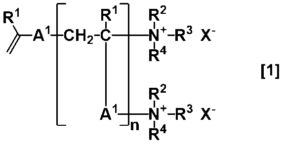
式中、R1は、それぞれ独立して、水素原子またはメチル基を表す。
R2、R3およびR4は、それぞれ独立して、水素原子、炭素数1~20の直鎖状、枝分かれ状または環状のアルキル基、炭素数7~20のアリールアルキル基、または-(CH2CH2O)mR5(式中、R5は水素原子またはメチル基を表し、mは2~100の任意の整数を表す。)を表す。
上記アルキル基およびアリールアルキル基は、アルコキシ基、ヒドロキシ基、アンモニウム基、カルボキシル基またはシアノ基で置換されていてもよい。また、R2、R3およびR4のうちの2つの基が一緒になって、直鎖状、枝分かれ状もしくは環状のアルキレン基を表すか、またはR2、R3およびR4ならびにそれらが結合する窒素原子が一緒になって環を形成してもよい。
X-は、陰イオンを表す。
nは、繰り返し単位構造の数であって、2~100,000の整数を表す。
R2、R3およびR4は、それぞれ独立して、水素原子、炭素数1~20の直鎖状、枝分かれ状または環状のアルキル基、炭素数7~20のアリールアルキル基、または-(CH2CH2O)mR5(式中、R5は水素原子またはメチル基を表し、mは2~100の任意の整数を表す。)を表す。
上記アルキル基およびアリールアルキル基は、アルコキシ基、ヒドロキシ基、アンモニウム基、カルボキシル基またはシアノ基で置換されていてもよい。また、R2、R3およびR4のうちの2つの基が一緒になって、直鎖状、枝分かれ状もしくは環状のアルキレン基を表すか、またはR2、R3およびR4ならびにそれらが結合する窒素原子が一緒になって環を形成してもよい。
X-は、陰イオンを表す。
nは、繰り返し単位構造の数であって、2~100,000の整数を表す。
上記R2、R3およびR4における炭素数1~20の直鎖状のアルキル基としては、メチル基、エチル基、n-プロピル基、n-ブチル基、n-ペンチル基、n-ヘキシル基、n-ヘプチル基、n-オクチル基、n-ノニル基、n-デシル基、n-ウンデシル基、n-ドデシル基、n-トリデシル基、n-テトラデシル基、n-ペンタデシル基、n-ヘキサデシル基、n-ヘプタデシル基、n-オクタデシル基、n-ノナデシル基、n-エイコシル基等が挙げられ、下地剤が(D)無電解銅層14の形成に用いる無電解めっき液に溶出しにくい点で、炭素数8以上の基が好ましく、特にn-オクチル基が好ましい。枝分かれ状のアルキル基としては、イソプロピル基、イソブチル基、sec-ブチル基、tert-ブチル基等が挙げられる。環状のアルキル基としては、シクロペンチル環、シクロヘキシル環構造を有する基等が挙げられる。
上記R2、R3およびR4における炭素数7~20のアリールアルキル基としては、ベンジル基、フェネチル基等が挙げられる。
上記R2、R3およびR4のうちの2つの基が一緒になった直鎖状のアルキレン基としては、メチレン基、エチレン基、n-プロピレン基、n-ブチレン基、n-ヘキシレン基等が挙げられる。枝分かれ状のアルキレン基としては、イソプロピレン基、イソブチレン基、2-メチルプロピレン基等が挙げられる。環状のアルキレン基としては、炭素数3~30の単環式、多環式、架橋環式の環状構造の脂環式脂肪族基が挙げられる。具体的には、炭素数4以上のモノシクロ、ビシクロ、トリシクロ、テトラシクロ、ペンタシクロ構造等を有する基を挙げることができる。これらアルキレン基は基中に窒素原子、硫黄原子または酸素原子を含んでいてもよい。
上記式[1]で表される構造でR2、R3およびR4ならびにそれらと結合する窒素原子が一緒になって形成する環は、環中に窒素原子、硫黄原子または酸素原子を含んでいても良く、例えばピリジン環、ピリミジン環、ピラジン環、キノリン環、ビピリジル環等が挙げられる。
上記X-の陰イオンとして好ましくはハロゲン原子、PF6
-、BF4
-またはパーフルオロアルカンスルホナートが挙げられる。
上記式[1]中、A1は下記式[2]で表される構造を表す。

式中、A2は、エーテル結合またはエステル結合を含んでいてもよい炭素数1~30の直鎖状、枝分かれ状または環状のアルキレン基を表す。
Y1、Y2、Y3およびY4は、それぞれ独立して、水素原子、炭素数1~20のアルキル基、炭素数1~20のアルコキシ基、ニトロ基、ヒドロキシ基、アミノ基、カルボキシル基またはシアノ基を表す。
Y1、Y2、Y3およびY4は、それぞれ独立して、水素原子、炭素数1~20のアルキル基、炭素数1~20のアルコキシ基、ニトロ基、ヒドロキシ基、アミノ基、カルボキシル基またはシアノ基を表す。
上記A2のアルキレン基の具体例としては、メチレン基、エチレン基、n-プロピレン基、n-ブチレン基、n-ヘキシレン基等の直鎖状アルキレン基、イソプロピレン基、イソブチレン基、2-メチルプロピレン基等の枝分かれ状アルキレン基が挙げられる。また、環状アルキレン基としては、炭素数3~30の単環式、多環式および架橋環式の環状構造の脂環式脂肪族基が挙げられる。具体的には、炭素数4以上のモノシクロ、ビシクロ、トリシクロ、テトラシクロ、ペンタシクロ構造等を有する基を挙げることができる。上記脂環式脂肪族基の脂環式部分の構造例としては、下記式(a)~(s)で表される構造が挙げられるが、これらに限定されるものではない。
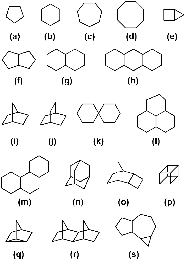
また、上記式[2]中のY1、Y2、Y3およびY4の炭素数1~20のアルキル基としては、メチル基、エチル基、イソプロピル基、シクロヘキシル基、n-ペンチル基等が挙げられる。炭素数1~20のアルコキシ基としては、メトキシ基、エトキシ基、イソプロポキシ基、シクロヘキシルオキシ基、n-ペンチルオキシ基等が挙げられる。Y1、Y2、Y3およびY4としては、それぞれ独立して、水素原子または炭素数1~20のアルキル基が好ましい。
なお、上記A1は下記式[4]で表される構造であることが好ましい。
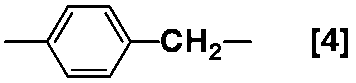
上記式[1]で表されるハイパーブランチポリマーの好適な態様としては、下記式[3]で表されるハイパーブランチポリマーが挙げられるが、これに限定されるものではない。
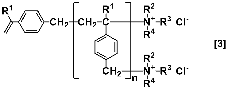
上記ハイパーブランチポリマーの重量平均分子量Mwは、好ましくは500~5,000,000、より好ましくは1,000~1,000,000、より一層好ましくは2,000~500,000であり、さらに好ましくは3,000~200,000である。また、分散度:Mw(重量平均分子量)/Mn(数平均分子量)は、好ましくは1.0~7.0、より好ましくは1.1~6.0であり、より一層好ましくは1.2~5.0である。
なお、重量平均分子量Mwは、ゲルパーミエーションクロマトグラフィーによるポリスチレン換算値である。
なお、重量平均分子量Mwは、ゲルパーミエーションクロマトグラフィーによるポリスチレン換算値である。
上記式[1]で表されるハイパーブランチポリマーは、公知の方法により合成することができる。例えば、国際公開第2012/141215号に記載された方法を参考とすることができ、分子末端にハロゲン原子を有するハイパーブランチポリマーにアミン化合物を反応させることによって得ることができる。
なお、分子末端にハロゲン原子を有するハイパーブランチポリマーは、国際公開第2008/029688号パンフレットの記載に従い、ジチオカルバメート基を分子末端に有するハイパーブランチポリマーより製造することができる。該ジチオカルバメート基を分子末端に有するハイパーブランチポリマーは、市販品を用いることができ、日産化学(株)製のハイパーテック(登録商標)HPS-200等を好適に使用可能である。
なお、分子末端にハロゲン原子を有するハイパーブランチポリマーは、国際公開第2008/029688号パンフレットの記載に従い、ジチオカルバメート基を分子末端に有するハイパーブランチポリマーより製造することができる。該ジチオカルバメート基を分子末端に有するハイパーブランチポリマーは、市販品を用いることができ、日産化学(株)製のハイパーテック(登録商標)HPS-200等を好適に使用可能である。
上記金属微粒子としては、公知のものを用いることができ、特に限定されるものではないが、金属種としては、鉄(Fe)、コバルト(Co)、ニッケル(Ni)、銅(Cu)、パラジウム(Pd)、銀(Ag)、スズ(Sn)、白金(Pt)および金(Au)が挙げられる。本発明では、これらの金属の1種類でもよいし、2種以上の合金でも構わない。これらの中でも、パラジウム微粒子が好ましい。なお、金属微粒子として、上記金属の酸化物を用いてもよい。
上記金属微粒子は、例えば、金属塩の水溶液を高圧水銀灯により光照射する方法や、該水溶液に還元作用を有する化合物(いわゆる還元剤)を添加する方法等により、金属イオンを還元することによって得られる。例えば、上記ハイパーブランチポリマーを溶解した溶液に金属塩の水溶液を添加してこれに紫外線を照射したり、或いは、該溶液に金属塩の水溶液および還元剤を添加するなどして、金属イオンを還元することにより、ハイパーブランチポリマーと金属微粒子の複合体を形成させながら、ハイパーブランチポリマーおよび金属微粒子を含む下地剤を調製することができる。
上記金属塩としては、塩化金酸、硝酸銀、硫酸銅、硝酸銅、酢酸銅、塩化スズ、塩化第一白金、塩化白金酸、Pt(dba)2[dba=ジベンジリデンアセトン]、Pt(cod)2[cod=1,5-シクロオクタジエン]、Pt(CH3)2(cod)、塩化パラジウム、酢酸パラジウム(Pd(OC(=O)CH3)2)、硝酸パラジウム、Pd2(dba)3・CHCl3、Pd(dba)2、Ni(cod)2等が挙げられる。
上記還元剤としては、特に限定されるものではなく、種々の還元剤を用いることができ、得られる下地剤に含有させる金属種等により還元剤を選択することが好ましい。用いることができる還元剤としては、例えば、水素化ホウ素ナトリウム、水素化ホウ素カリウム等の水素化ホウ素金属塩;水素化アルミニウムリチウム、水素化アルミニウムカリウム、水素化アルミニウムセシウム、水素化アルミニウムベリリウム、水素化アルミニウムマグネシウム、水素化アルミニウムカルシウム等の水素化アルミニウム塩;ヒドラジン化合物;クエン酸およびその塩;コハク酸およびその塩;アスコルビン酸およびその塩;メタノール、エタノール、イソプロパノール、ポリオール等の第一級または第二級アルコール類;トリメチルアミン、トリエチルアミン、ジイソプロピルエチルアミン、ジエチルメチルアミン、テトラメチルエチレンジアミン[TMEDA]、エチレンジアミン四酢酸[EDTA]等の第三級アミン類;ヒドロキシルアミン;トリ-n-プロピルホスフィン、トリ-n-ブチルホスフィン、トリシクロヘキシルホスフィン、トリベンジルホスフィン、トリフェニルホスフィン、トリエトキシホスフィン、1,2-ビス(ジフェニルホスフィノ)エタン[DPPE]、1,3-ビス(ジフェニルホスフィノ)プロパン[DPPP]、1,1’-ビス(ジフェニルホスフィノ)フェロセン[DPPF]、2,2’-ビス(ジフェニルホスフィノ)-1,1’-ビナフチル[BINAP]等のホスフィン類等が挙げられる。
上記金属微粒子の平均粒径は1~100nmが好ましい。その理由としては、該金属微粒子の平均粒径が100nmを超えると、表面積が減少し触媒活性が低下するためである。平均粒径としては、75nm以下が更に好ましく、1~30nmが特に好ましい。
上記下地剤における上記ハイパーブランチポリマーの含有量は、上記金属微粒子100質量部に対し、50~2,000質量部が好ましい。50質量部未満であると、上記金属微粒子の分散性が不充分であり、2,000質量部を超えると、有機物含有量が多くなり、物性等に不具合が生じやすくなる。より好ましくは100~1,000質量部である。
<ハイパーブランチポリマーと金属微粒子とを含む下地剤>
上記下地剤は、上述したアンモニウム基を分子末端に有するハイパーブランチポリマーと金属微粒子とを含むものであり、このとき、上記ハイパーブランチポリマーと上記金属微粒子が複合体を形成していることが好ましい。ここで複合体とは、上記ハイパーブランチポリマーの末端のアンモニウム基の作用により、金属微粒子に接触または近接した状態で両者が共存し、粒子状の形態を為すものであり、言い換えると、上記ハイパーブランチポリマーのアンモニウム基が金属微粒子に付着または配位した構造を有する複合体であると表現される。
従って、本発明における「複合体」には、上述のように金属微粒子とハイパーブランチポリマーが結合して一つの複合体を形成しているものだけでなく、金属微粒子とハイパーブランチポリマーが結合部分を形成することなく、それぞれ独立して存在しているものも含まれていてもよい。
上記下地剤は、上述したアンモニウム基を分子末端に有するハイパーブランチポリマーと金属微粒子とを含むものであり、このとき、上記ハイパーブランチポリマーと上記金属微粒子が複合体を形成していることが好ましい。ここで複合体とは、上記ハイパーブランチポリマーの末端のアンモニウム基の作用により、金属微粒子に接触または近接した状態で両者が共存し、粒子状の形態を為すものであり、言い換えると、上記ハイパーブランチポリマーのアンモニウム基が金属微粒子に付着または配位した構造を有する複合体であると表現される。
従って、本発明における「複合体」には、上述のように金属微粒子とハイパーブランチポリマーが結合して一つの複合体を形成しているものだけでなく、金属微粒子とハイパーブランチポリマーが結合部分を形成することなく、それぞれ独立して存在しているものも含まれていてもよい。
上記ハイパーブランチポリマーと金属微粒子の複合体の形成は、ハイパーブランチポリマーと金属微粒子を含む下地剤の調製時に同時に実施され、その方法としては、低級アンモニウム配位子によりある程度安定化した金属微粒子を合成した後にハイパーブランチポリマーにより配位子を交換する方法や、アンモニウム基を有するハイパーブランチポリマーの溶液中で、金属イオンを直接還元することにより複合体を形成する方法がある。また、上述のように、上記ハイパーブランチポリマーを溶解した溶液に金属塩の水溶液を添加してこれに紫外線を照射したり、あるいは、該溶液に金属塩の水溶液および還元剤を添加するなどして、金属イオンを還元することによっても複合体を形成できる。
配位子交換法において、原料となる低級アンモニウム配位子によりある程度安定化した金属微粒子は、Jounal of Organometallic Chemistry 1996,520,143-162等に記載の方法で合成することができる。得られた金属微粒子の反応混合溶液に、アンモニウム基を有するハイパーブランチポリマーを溶解し、室温(およそ25℃)または加熱撹拌することにより目的とする金属微粒子複合体を得ることができる。
使用する溶媒としては、ハイパーブランチポリマーと金属微粒子とを必要濃度以上に溶解できる溶媒であれば特に限定はされないが、具体的には、エタノール、プロパノール、イソプロパノール等のアルコール類;塩化メチレン、クロロホルム等のハロゲン化炭化水素類;テトラヒドロフラン、2-メチルテトラヒドロフラン、テトラヒドロピラン等の環状エーテル類;アセトニトリル、ブチロニトリル等のニトリル類等、およびこれらの溶媒の混合液が挙げられる。本発明では、これらの中でもテトラヒドロフランが好ましい。
金属微粒子の反応混合液と、アンモニウム基を有するハイパーブランチポリマーを混合する温度は、通常0℃~使用する溶媒の沸点の範囲を採用することができ、好ましくは、室温(およそ25℃)~60℃の範囲である。
なお、配位子交換法において、アミン系分散剤(低級アンモニウム配位子)以外にホスフィン系分散剤(ホスフィン配位子)を用いることによっても、あらかじめ金属微粒子をある程度安定化することができる。
直接還元方法としては、金属イオンとアンモニウム基を有するハイパーブランチポリマーを溶媒に溶解し、水素ガス雰囲気下で反応させることにより、目的とする金属微粒子複合体を得ることができる。
ここで用いられる金属イオン源としては、上述の金属塩や、ヘキサカルボニルクロム[Cr(CO)6]、ペンタカルボニル鉄[Fe(Co)5]、オクタカルボニルジコバルト[Co2(CO)8]、テトラカルボニルニッケル[Ni(CO)4]等の金属カルボニル錯体が使用できる。また、金属オレフィン錯体や金属ホスフィン錯体、金属窒素錯体等の0価の金属錯体も使用できる。
ここで用いられる金属イオン源としては、上述の金属塩や、ヘキサカルボニルクロム[Cr(CO)6]、ペンタカルボニル鉄[Fe(Co)5]、オクタカルボニルジコバルト[Co2(CO)8]、テトラカルボニルニッケル[Ni(CO)4]等の金属カルボニル錯体が使用できる。また、金属オレフィン錯体や金属ホスフィン錯体、金属窒素錯体等の0価の金属錯体も使用できる。
使用する溶媒としては、金属イオンとアンモニウム基を有するハイパーブランチポリマーを必要濃度以上に溶解できる溶媒であれば特に限定はされないが、具体的には、エタノール、プロパノール等のアルコール類;塩化メチレン、クロロホルム等のハロゲン化炭化水素類;テトラヒドロフラン、2-メチルテトラヒドロフラン、テトラヒドロピラン等の環状エーテル類;アセトニトリル、ブチロニトリル等のニトリル類等、およびこれらの溶媒の混合液が挙げられる。本発明では、これらの中でもテトラヒドロフランが好ましい。
金属イオンとアンモニウム基を有するハイパーブランチポリマーを混合する温度は、通常0℃~使用する溶媒の沸点の範囲を採用することができる。
金属イオンとアンモニウム基を有するハイパーブランチポリマーを混合する温度は、通常0℃~使用する溶媒の沸点の範囲を採用することができる。
また、直接還元方法として、金属イオンとアンモニウム基を有するハイパーブランチポリマーを溶媒に溶解し、熱分解反応させることにより、目的とする金属微粒子複合体を得ることができる。
ここで用いられる金属イオン源としては、上述の金属塩や金属カルボニル錯体やその他の0価の金属錯体、酸化銀等の金属酸化物が使用できる。
使用する溶媒としては、金属イオンとアンモニウム基を有するハイパーブランチポリマーを必要濃度以上に溶解できる溶媒であれば特に限定はされないが、具体的には、メタノール、エタノール、n-プロパノール、イソプロパノール、エチレングリコール等のアルコール類;塩化メチレン、クロロホルム等のハロゲン化炭化水素類;テトラヒドロフラン、2-メチルテトラヒドロフラン、テトラヒドロピラン等の環状エーテル類;アセトニトリル、ブチロニトリル等のニトリル類;ベンゼン、トルエン等の芳香族炭化水素類等、およびこれらの溶媒の混合液が挙げられる。本発明では、これらの中でもトルエンが好ましい。
金属イオンとアンモニウム基を有するハイパーブランチポリマーを混合する温度は、通常0℃~使用する溶媒の沸点の範囲を採用することができ、好ましくは溶媒の沸点近傍、例えば、トルエンの場合は110℃(加熱還流)である。
こうして得られるアンモニウム基を有するハイパーブランチポリマーと金属微粒子の複合体は、再沈殿等の精製処理を経て、粉末などの固形物の形態とすることができる。
上記下地剤は、上記アンモニウム基を有するハイパーブランチポリマーと金属微粒子(好ましくはこれらよりなる複合体)とを含むものであって、後述する無電解めっき触媒層13の形成時に用いるワニスの形態であってもよい。
<無電解めっき触媒層13の形成>
(C)無電解めっき触媒層13は、上記下地剤を上記(B)有機薄膜からなる剥離層12上に塗布することにより形成することができる。
具体的には、まず、上記アンモニウム基を有するハイパーブランチポリマーと金属微粒子(好ましくはこれらよりなる複合体)を適当な溶媒に溶解または分散してワニスの形態とし、該ワニスを上記(B)有機薄膜からなる剥離層12上に塗布し、その後、溶媒を蒸発・乾燥させることにより、薄層を形成することができる。
(C)無電解めっき触媒層13は、上記下地剤を上記(B)有機薄膜からなる剥離層12上に塗布することにより形成することができる。
具体的には、まず、上記アンモニウム基を有するハイパーブランチポリマーと金属微粒子(好ましくはこれらよりなる複合体)を適当な溶媒に溶解または分散してワニスの形態とし、該ワニスを上記(B)有機薄膜からなる剥離層12上に塗布し、その後、溶媒を蒸発・乾燥させることにより、薄層を形成することができる。
下地剤の塗布方法としては、公知の方法を採用でき、特に限定されるものではないが、スピンコート法;ブレードコート法;ディップコート法;ロールコート法;バーコート法;ダイコート法;スプレーコート法;インクジェット法;ファウンテンペンナノリソグラフィー(FPN)、ディップペンナノリソグラフィー(DPN)等のペンリソグラフィー;活版印刷、フレキソ印刷、樹脂凸版印刷、コンタクトプリンティング、マイクロコンタクトプリンティング(μCP)、ナノインプリンティングリソグラフィー(NIL)、ナノトランスファープリンティング(nTP)などの凸版印刷法;グラビア印刷、エングレービング等の凹版印刷法;平版印刷法;スクリーン印刷、謄写版等の孔版印刷法;オフセット印刷法等が挙げられる。
本発明では、これらの塗布方法の中でもスピンコート法、スプレーコート法、インクジェット法、ペンリソグラフィー、コンタクトプリンティング、μCP、NILおよびnTPが好ましい。スピンコート法を用いる場合には、単時間で塗布することができるために、揮発性の高い溶液であっても利用でき、また、均一性の高い塗布を行うことができるという利点がある。スプレーコート法を用いる場合には、極少量のワニスで均一性の高い塗布を行うことができ、工業的に非常に有利となる。
また、ここで用いられる溶媒としては、上記複合体を溶解または分散するものであれば特に限定されないが、例えば、水;ベンゼン、トルエン、キシレン、エチルベンゼン、クロロベンゼン、ジクロロベンゼン等の芳香族炭化水素類;メタノール、エタノール、イソプロパノール等のアルコール類;テトラヒドロフラン、メチルテトラヒドロフラン、1,4-ジオキサン、ジエチルエーテル、ジエチレングリコールジメチルエーテル、プロピレングリコールメチルエーテル等のエーテル類;酢酸エチル等のエステル類;アセトン、エチルメチルケトン、イソブチルメチルケトン、シクロペンタノン、シクロヘキサノン等のケトン類;n-ヘプタン、n-ヘキサン、シクロヘキサン等の脂肪族炭化水素類;1,2-ジクロロエタン、クロロホルム等のハロゲン化脂肪族炭化水素類;N-メチル-2-ピロリドン、N,N-ジメチルホルムアミド、N,N-ジメチルアセトアミド等のアミド類;ジメチルスルホキシド等が挙げられる。これらの溶媒は、1種を単独で使用してもよく、2種以上の溶媒を混合してもよい。さらに、ワニスの粘度を調整する目的で、エチレングリコール、プロピレングリコール、ブチレングリコール等のグリコール類を添加してもよい。
また、上記溶媒に溶解または分散させる濃度は任意であるが、ワニス中の上記複合体濃度は0.05~90質量%が好ましく、より好ましくは0.1~80質量%である。
溶媒の乾燥法としては、特に限定されるものではなく、例えば、ホットプレートやオーブンを用いて、適切な雰囲気下、すなわち大気、窒素等の不活性ガス、真空中等で蒸発させればよい。これにより、均一な成膜面を有する無電解めっき触媒層13を得ることができる。焼成温度は、溶媒を蒸発させることができれば特に限定されないが、40~250℃で行うことが好ましい。
上記無電解めっき触媒層13の厚さは、通常0.01~50μm程度、生産性の観点から、好ましくは0.01~20μm程度、より好ましくは0.01~10μm程度であり、加熱前の塗膜の厚さを調整して所望の厚さを実現する。
(D)無電解銅層14
上記のようにして形成された無電解めっき触媒層13を所定のめっき液を用いて無電解めっき処理することにより、無電解めっき触媒層13の上に無電解銅層14が形成される。無電解めっき処理(工程)は特に限定されず、一般的に知られている何れの無電解めっき処理にて行うことができ、例えば、従来一般に知られている無電解めっき液を用い、該めっき液(浴)に基材上に形成された無電解めっき下地層を浸漬する方法が挙げられる。
上記のようにして形成された無電解めっき触媒層13を所定のめっき液を用いて無電解めっき処理することにより、無電解めっき触媒層13の上に無電解銅層14が形成される。無電解めっき処理(工程)は特に限定されず、一般的に知られている何れの無電解めっき処理にて行うことができ、例えば、従来一般に知られている無電解めっき液を用い、該めっき液(浴)に基材上に形成された無電解めっき下地層を浸漬する方法が挙げられる。
上記無電解めっき液としては、主として金属イオン(金属塩)、錯化剤および還元剤を含有し、その他用途に合わせてpH調整剤、pH緩衝剤、反応促進剤(第二錯化剤)、安定剤、界面活性剤(被処理面の濡れ性改善用途等)等が適宜含まれているものを用いることができる。
本発明において、無電解めっきで形成される金属めっき膜に用いられる金属としては、銅が用いられる。なお、本発明の効果を損なわない範囲において、鉄、コバルト、ニッケル、パラジウム、銀、スズ、白金および金からなる群より選択される少なくとも1種の金属を含んでいてもよい。
上記錯化剤、還元剤についても金属イオンに応じて適宜選択すればよい。
また、無電解銅層を形成するための無電解めっき液は、市販のめっき液を使用してもよい。市販品の具体例としては、アトテック(株)製の無電解めっき液(プリントガント(登録商標)PVG2)、メルテックス(株)製の無電解銅めっき薬品(メルプレートCUシリーズ)、奥野製薬工業(株)製の無電解ニッケルめっき液(ICPニコロンシリーズ)、無電解銅めっき液(OPC-700無電解銅M-K、ATSアドカッパーIW)等が挙げられる。
また、無電解銅層を形成するための無電解めっき液は、市販のめっき液を使用してもよい。市販品の具体例としては、アトテック(株)製の無電解めっき液(プリントガント(登録商標)PVG2)、メルテックス(株)製の無電解銅めっき薬品(メルプレートCUシリーズ)、奥野製薬工業(株)製の無電解ニッケルめっき液(ICPニコロンシリーズ)、無電解銅めっき液(OPC-700無電解銅M-K、ATSアドカッパーIW)等が挙げられる。
また、銅以外の金属を含むめっき液の具体例としては、メルテックス(株)製の無電解ニッケルめっき薬品(メルプレートNIシリーズ)、無電解スズめっき液(サブスターSN-5)、無電解金めっき液(フラッシュゴールド330、セルフゴールドOTK-IT)、小島化学薬品(株)製の無電解パラジウムめっき液(パレットII)、無電解金めっき液(ディップGシリーズ、NCゴールドシリーズ)、佐々木化学薬品(株)製の無電解銀めっき液(エスダイヤAG-40)、日本カニゼン(株)製の無電解ニッケルめっき液(シューマー(登録商標)シリーズ、シューマー(登録商標)カニブラック(登録商標)シリーズ)、無電解パラジウムめっき液(S-KPD)等が挙げられる。
上記無電解めっき工程は、めっき浴の温度、pH、浸漬時間、金属イオン濃度、撹拌の有無や撹拌速度、空気・酸素の供給の有無や供給速度等を調節することにより、金属被膜の形成速度や膜厚を制御することができる。
無電解銅層14の厚さは、フラッシュエッチング時のサイドエッチを軽減する点から、2μm以下が好ましく、1.0μm以下がより好ましく、0.5μm以下がより一層好ましく、0.2μm以下がさらに好ましい。下限は特に限定されるものではないが、通常0.05μm以上である。
本発明では、無電解めっき処理を採用することにより、無電解銅層14をより薄く形成することができる。無電解銅層14を薄く形成することにより、銅の使用量を削減できることに加え、プリント配線基板の配線形成工程において、フラッシュエッチング時のサイドエッチが低減され、その結果、配線をより微細化することができるようになる。
[積層体]
本発明の積層体10は、支持基材11上に、有機薄膜からなる剥離層12と、無電解めっき触媒層13と、上述した方法および条件で順番に積層することにより得られる。
さらに、上記積層体10の無電解めっき触媒層13上に、無電解銅層14と、上述した方法および条件で積層することにより、本発明の積層体1(無電解銅層積層体1)を得ることができる。
本発明の積層体10は、支持基材11上に、有機薄膜からなる剥離層12と、無電解めっき触媒層13と、上述した方法および条件で順番に積層することにより得られる。
さらに、上記積層体10の無電解めっき触媒層13上に、無電解銅層14と、上述した方法および条件で積層することにより、本発明の積層体1(無電解銅層積層体1)を得ることができる。
[プリント配線基板の製造方法]
図3に、本発明の積層体1(無電解銅層積層体1)を用いたプリント配線基板の製造工程フローの一例を示した。本発明の積層体1を用いたプリント配線基板の製造方法の一例について以下に説明する。
図3に、本発明の積層体1(無電解銅層積層体1)を用いたプリント配線基板の製造工程フローの一例を示した。本発明の積層体1を用いたプリント配線基板の製造方法の一例について以下に説明する。
まず、本発明の積層体1の無電解銅層14と、樹脂基板2とを対向させて圧着し、積層体1と樹脂基板2との複合材を得る(同図(1)、(2))。この際、無電解銅層14と樹脂基板2との接着性を向上させるため、熱可塑性樹脂や熱硬化性樹脂を用いた接着層を介してもよい。
剥離層12と無電解めっき触媒層13との界面で剥離し、無電解銅層14を樹脂基板2側に転写し、樹脂基板2上に無電解銅層14および無電解めっき触媒層13が積層されたプリント配線基板用シード層Sを得る(同図(3))。
プリント配線基板用シード層S上の無電解めっき触媒層13の全面に感光性レジストを塗工し(図示せず)、露光、現像工程を経て、めっき必要部に開口を有するフォトレジスト層3を形成する(同図(4))。
この開口部に電解めっき処理により配線パターン4を形成する(同図(5))。
フォトレジスト層3をレジスト剥離液で除去した後、フラッシュエッチングにより、配線パターン4間に残った無電解めっき触媒層13および無電解銅層14を除去し、目的とする配線パターン4が形成されたプリント配線基板Pが得られる(同図(6))。
剥離層12と無電解めっき触媒層13との界面で剥離し、無電解銅層14を樹脂基板2側に転写し、樹脂基板2上に無電解銅層14および無電解めっき触媒層13が積層されたプリント配線基板用シード層Sを得る(同図(3))。
プリント配線基板用シード層S上の無電解めっき触媒層13の全面に感光性レジストを塗工し(図示せず)、露光、現像工程を経て、めっき必要部に開口を有するフォトレジスト層3を形成する(同図(4))。
この開口部に電解めっき処理により配線パターン4を形成する(同図(5))。
フォトレジスト層3をレジスト剥離液で除去した後、フラッシュエッチングにより、配線パターン4間に残った無電解めっき触媒層13および無電解銅層14を除去し、目的とする配線パターン4が形成されたプリント配線基板Pが得られる(同図(6))。
なお、上記製造方法では、プリント配線基板用シード層Sの無電解めっき触媒層13の上に配線パターン4を形成する方法を示したが、必要に応じて、図4のように感光性レジストを塗工する前に、無電解めっき触媒層13をパラジウムエッチング液等の処理液を用いて除去してもよい(同図(4)。この場合、プリント配線基板用シード層Sは、樹脂基板2上に無電解銅層14が積層されたものとなる。)。これにより、配線パターン4が無電解銅層14の直上に形成されることとなり、その結果として、電気信号へのノイズを抑制することが期待される。
また、得られたプリント配線基板Pは、特性悪化を防ぐため、定法に従い、必要に応じて捕水剤等とともに封止してもよい。
本発明の無電解銅層積層体1において、剥離層12と無電解めっき触媒層13との界面で剥離する際の剥離力は、無電解銅層14を傷つけることなく容易に剥離する点から、好ましくは0.020N/mm以下、より好ましくは0.010N/mm未満、より一層好ましくは0.005N/mm以下である。一方、上記剥離力の下限は特に限定されないが、無電解銅層14を支持基材11上に安定して固定する点から、好ましくは0.001N/mm以上、より好ましくは0.0015N/mm以上である。
以下、本発明の実施例を挙げて、本発明を具体的に説明するが、本発明はこれらに限定して解釈されるものではない。
下記例で使用した化合物の略語は、以下のとおりである。
PGME:プロピレングリコールモノメチルエーテル
PGMEA:プロピレングリコールモノメチルエーテルアセテート
PL-LI:1,3,4,6-テトラキス(メトキシエチル)グリコールウリル(オルネクス社製、商品名:POWDERLINK 1174)
PPTS:p-トルエンスルホン酸ピリジニウム
HPMA:メタクリル酸2-ヒドロキシプロピル
ADMA:メタクリル酸2-アダマンチル
HFiPMA:メタクリル酸1,1,1,3,3,3-ヘキサフルオロイソプロピル
HADM:メタクリル酸3-ヒドロキシ-1-アダマンチル
DCP:ジシクロペンタニルメタクリレート
BuMA:ブチルメタクリレート
AIBN:アゾビスイソブチロニトリル
DDT:ドデカンチオール
IPA:イソプロピルアルコール
IPE:ジイソプロピルエーテル
DEGMEE:ジエチレングリコールモノエチルエーテル
PGME:プロピレングリコールモノメチルエーテル
PGMEA:プロピレングリコールモノメチルエーテルアセテート
PL-LI:1,3,4,6-テトラキス(メトキシエチル)グリコールウリル(オルネクス社製、商品名:POWDERLINK 1174)
PPTS:p-トルエンスルホン酸ピリジニウム
HPMA:メタクリル酸2-ヒドロキシプロピル
ADMA:メタクリル酸2-アダマンチル
HFiPMA:メタクリル酸1,1,1,3,3,3-ヘキサフルオロイソプロピル
HADM:メタクリル酸3-ヒドロキシ-1-アダマンチル
DCP:ジシクロペンタニルメタクリレート
BuMA:ブチルメタクリレート
AIBN:アゾビスイソブチロニトリル
DDT:ドデカンチオール
IPA:イソプロピルアルコール
IPE:ジイソプロピルエーテル
DEGMEE:ジエチレングリコールモノエチルエーテル

以下の実施例において、試料の物性測定は、下記の条件のもとで下記の装置を使用して行った。
(1)GPC(ゲル浸透クロマトグラフィー)
[合成例1-1~1-6]
装置:日本分光(株)製GPC装置(合成例)
カラム:昭和電工(株)製Shodex(登録商標)KD801+KD805
カラム温度:40℃
溶媒:ジメチルホルムアミド/LiBr・H2O(29.6mM)/H3PO4(29.6mM)/テトラヒドロフラン(0.1質量%)
検出器:UV(254nm)、RI
[合成例2-1、2-2、2-4]
装置:東ソー(株)製 HLC-8220GPC
カラム:昭和電工(株)製Shodex(登録商標)KF-804L+KF-803L
カラム温度:40℃
溶媒:テトラヒドロフラン
検出器:UV(254nm)、RI
(2)1H-NMRスペクトル
装置:日本電子(株)製 JNM-L400
溶媒:CDCl3
内部標準:テトラメチルシラン(0.00ppm)
(3)13C-NMRスペクトル
装置:日本電子(株)製 JNM-ECA700
溶媒:CDCl3
緩和試薬:トリスアセチルアセトナートクロム(Cr(acac)3)
基準:CDCl3(77.0ppm)
(4)TEM(透過型電子顕微鏡)
[合成例2-3]
装置:(株)日立製作所製 HT-7700
加速電圧:100kV
[合成例2-5]
装置:(株)日立製作所製 H-8000
加速電圧:200kV
(5)ICP発光分析(誘導結合プラズマ発光分析)
[合成例2-3]
装置:Agilent Technologies製 5110
[合成例2-5]
装置:(株)島津製作所製 ICPM-8500
(6)蛍光X線膜厚測定
装置:(株)電測製 蛍光X線式膜厚計 EX-731
エネルギー範囲:67~96
コリメータ:0.5mmφ
X線出力:11
(7)剥離力測定
装置:(株)島津製作所製 オートグラフAGS-X500N
剥離角度:180°
剥離速度:300mm/min
(1)GPC(ゲル浸透クロマトグラフィー)
[合成例1-1~1-6]
装置:日本分光(株)製GPC装置(合成例)
カラム:昭和電工(株)製Shodex(登録商標)KD801+KD805
カラム温度:40℃
溶媒:ジメチルホルムアミド/LiBr・H2O(29.6mM)/H3PO4(29.6mM)/テトラヒドロフラン(0.1質量%)
検出器:UV(254nm)、RI
[合成例2-1、2-2、2-4]
装置:東ソー(株)製 HLC-8220GPC
カラム:昭和電工(株)製Shodex(登録商標)KF-804L+KF-803L
カラム温度:40℃
溶媒:テトラヒドロフラン
検出器:UV(254nm)、RI
(2)1H-NMRスペクトル
装置:日本電子(株)製 JNM-L400
溶媒:CDCl3
内部標準:テトラメチルシラン(0.00ppm)
(3)13C-NMRスペクトル
装置:日本電子(株)製 JNM-ECA700
溶媒:CDCl3
緩和試薬:トリスアセチルアセトナートクロム(Cr(acac)3)
基準:CDCl3(77.0ppm)
(4)TEM(透過型電子顕微鏡)
[合成例2-3]
装置:(株)日立製作所製 HT-7700
加速電圧:100kV
[合成例2-5]
装置:(株)日立製作所製 H-8000
加速電圧:200kV
(5)ICP発光分析(誘導結合プラズマ発光分析)
[合成例2-3]
装置:Agilent Technologies製 5110
[合成例2-5]
装置:(株)島津製作所製 ICPM-8500
(6)蛍光X線膜厚測定
装置:(株)電測製 蛍光X線式膜厚計 EX-731
エネルギー範囲:67~96
コリメータ:0.5mmφ
X線出力:11
(7)剥離力測定
装置:(株)島津製作所製 オートグラフAGS-X500N
剥離角度:180°
剥離速度:300mm/min
[1]ポリマーの合成
[合成例1-1]ポリウレアの合成
モノアリルジグリシジルイソシアヌル酸(四国化成工業(株)製)100g、5,5-ジエチルバルビツール酸66.4gおよびベンジルトリエチルアンモニウムクロリド4.1gをPGME682gに溶解させた後、130℃で24時間反応させ、ポリウレアを含む溶液(固形分濃度20質量%)を得た。GPC分析の結果、得られたポリウレアのMwは8,000、Mw/Mnは1.5であった。
[合成例1-1]ポリウレアの合成
モノアリルジグリシジルイソシアヌル酸(四国化成工業(株)製)100g、5,5-ジエチルバルビツール酸66.4gおよびベンジルトリエチルアンモニウムクロリド4.1gをPGME682gに溶解させた後、130℃で24時間反応させ、ポリウレアを含む溶液(固形分濃度20質量%)を得た。GPC分析の結果、得られたポリウレアのMwは8,000、Mw/Mnは1.5であった。
[合成例1-2]フッ素含有ポリマー(S1)の合成
HFiPMA8.04g、HPMA4.91g、ADMA10.00gおよびAIBN0.93g、DDT1.15gをPGME100.10gに溶解し、70℃にて20時間反応させ、アクリルポリマー(S1)溶液(固形分濃度20質量%)を得た。各単位の組成比は、HFiPMA:HPMA:ADMA=30:30:40(モル比)であった。GPC分析の結果、得られたアクリルポリマー(S1)のMwは5,310、Mw/Mnは1.8であった。
HFiPMA8.04g、HPMA4.91g、ADMA10.00gおよびAIBN0.93g、DDT1.15gをPGME100.10gに溶解し、70℃にて20時間反応させ、アクリルポリマー(S1)溶液(固形分濃度20質量%)を得た。各単位の組成比は、HFiPMA:HPMA:ADMA=30:30:40(モル比)であった。GPC分析の結果、得られたアクリルポリマー(S1)のMwは5,310、Mw/Mnは1.8であった。
[合成例1-3]フッ素含有ポリマー(S2)の合成
HFiPMA53.6g、HPMA16.4g、ADMA50.0gおよびAIBN4.66g、DDT5.74gをPGME521.4gに溶解し、70℃にて20時間反応させ、アクリルポリマー(S2)溶液(固形分濃度20質量%)を得た。各単位の組成比(モル比)は、HFiPMA:HPMA:ADMA=40:20:40であった。GPC分析の結果、得られたアクリルポリマー(S2)のMwは5,370、Mw/Mnは1.8であった。
HFiPMA53.6g、HPMA16.4g、ADMA50.0gおよびAIBN4.66g、DDT5.74gをPGME521.4gに溶解し、70℃にて20時間反応させ、アクリルポリマー(S2)溶液(固形分濃度20質量%)を得た。各単位の組成比(モル比)は、HFiPMA:HPMA:ADMA=40:20:40であった。GPC分析の結果、得られたアクリルポリマー(S2)のMwは5,370、Mw/Mnは1.8であった。
[合成例1-4]フッ素含有ポリマー(S3)の合成
HFiPMA6.43g、HADM3.22g、ADMA6.00gおよびAIBN0.56g、DDT0.69gをPGME67.6gに溶解し、70℃にて20時間反応させ、アクリルポリマー(S3)溶液(固形分濃度20質量%)を得た。各単位の組成比(モル比)は、HFiPMA:HADM:ADMA=40:20:40であった。GPC分析の結果、得られたアクリルポリマー(S3)のMwは5,520、Mw/Mnは1.8であった。
HFiPMA6.43g、HADM3.22g、ADMA6.00gおよびAIBN0.56g、DDT0.69gをPGME67.6gに溶解し、70℃にて20時間反応させ、アクリルポリマー(S3)溶液(固形分濃度20質量%)を得た。各単位の組成比(モル比)は、HFiPMA:HADM:ADMA=40:20:40であった。GPC分析の結果、得られたアクリルポリマー(S3)のMwは5,520、Mw/Mnは1.8であった。
[合成例1-5]フッ素含有ポリマー(S4)の合成
HFiPMA9.16g、HPMA2.80g、DCP8.00gおよびAIBN0.80g、DDT0.98gをPGME86.9gに溶解し、70℃にて20時間反応させ、アクリルポリマー(S4)溶液(固形分濃度20質量%)を得た。各単位の組成比(モル比)は、HFiPMA:HPMA:DCP=40:20:40であった。GPC分析の結果、得られたアクリルポリマー(S4)のMwは5,970、Mw/Mnは1.9であった。
HFiPMA9.16g、HPMA2.80g、DCP8.00gおよびAIBN0.80g、DDT0.98gをPGME86.9gに溶解し、70℃にて20時間反応させ、アクリルポリマー(S4)溶液(固形分濃度20質量%)を得た。各単位の組成比(モル比)は、HFiPMA:HPMA:DCP=40:20:40であった。GPC分析の結果、得られたアクリルポリマー(S4)のMwは5,970、Mw/Mnは1.9であった。
[合成例1-6]フッ素含有ポリマー(S5)の合成
HFiPMA6.97g、HPMA2.84g、BuMA7.00gおよびAIBN0.81g、DDT1.00gをPGME74.4gに溶解し、70℃にて20時間反応させ、アクリルポリマー(S5)溶液(固形分濃度20質量%)を得た。各単位の組成比(モル比)は、HFiPMA:HPMA:BuMA=30:20:50であった。GPC分析の結果、得られたアクリルポリマー(S5)のMwは4,840、Mw/Mnは2.0であった。
HFiPMA6.97g、HPMA2.84g、BuMA7.00gおよびAIBN0.81g、DDT1.00gをPGME74.4gに溶解し、70℃にて20時間反応させ、アクリルポリマー(S5)溶液(固形分濃度20質量%)を得た。各単位の組成比(モル比)は、HFiPMA:HPMA:BuMA=30:20:50であった。GPC分析の結果、得られたアクリルポリマー(S5)のMwは4,840、Mw/Mnは2.0であった。
[2]Pd粒子複合体の合成
[合成例2-1]HPS-Clの合成

[合成例2-1]HPS-Clの合成
HPS-Clは、国際公開第2012/141215号に記載された方法に従い、以下のように合成した。
500mLの反応フラスコに、塩化スルフリル[キシダ化学(株)製]27gおよびクロロホルム50gを仕込み、撹拌して均一に溶解させた。この溶液を窒素気流下0℃まで冷却した。
別の300mLの反応フラスコに、ジチオカルバメート基を分子末端に有するハイパーブランチポリマーHPS15gおよびクロロホルム150gを仕込み、窒素気流下均一になるまで撹拌した。
前述の0℃に冷却されている塩化スルフリル/クロロホルム溶液中に、窒素気流下、HPS/クロロホルム溶液が仕込まれた上記300mLの反応フラスコから、送液ポンプを用いて、該溶液を反応液の温度が-5~5℃となるように60分間かけて加えた。添加終了後、反応液の温度を-5~5℃に保持しながら6時間撹拌した。
さらにこの反応液へ、シクロヘキセン[東京化成工業(株)製]16gをクロロホルム50gに溶かした溶液を、反応液の温度が-5~5℃となるように加えた。添加終了後、この反応液をIPA1,200gに添加してポリマーを沈殿させた。この沈殿をろ取して得られた白色粉末をクロロホルム100gに溶解し、これをIPA500gに添加してポリマーを再沈殿させた。この沈殿物を減圧ろ過し、真空乾燥して、塩素原子を分子末端に有するハイパーブランチポリマー(HPS-Cl)8.5gを白色粉末として得た(収率99%)。
得られたHPS-ClのGPCによるポリスチレン換算で測定される重量平均分子量Mwは14,000、分散度Mw/Mnは2.9であった。
500mLの反応フラスコに、塩化スルフリル[キシダ化学(株)製]27gおよびクロロホルム50gを仕込み、撹拌して均一に溶解させた。この溶液を窒素気流下0℃まで冷却した。
別の300mLの反応フラスコに、ジチオカルバメート基を分子末端に有するハイパーブランチポリマーHPS15gおよびクロロホルム150gを仕込み、窒素気流下均一になるまで撹拌した。
前述の0℃に冷却されている塩化スルフリル/クロロホルム溶液中に、窒素気流下、HPS/クロロホルム溶液が仕込まれた上記300mLの反応フラスコから、送液ポンプを用いて、該溶液を反応液の温度が-5~5℃となるように60分間かけて加えた。添加終了後、反応液の温度を-5~5℃に保持しながら6時間撹拌した。
さらにこの反応液へ、シクロヘキセン[東京化成工業(株)製]16gをクロロホルム50gに溶かした溶液を、反応液の温度が-5~5℃となるように加えた。添加終了後、この反応液をIPA1,200gに添加してポリマーを沈殿させた。この沈殿をろ取して得られた白色粉末をクロロホルム100gに溶解し、これをIPA500gに添加してポリマーを再沈殿させた。この沈殿物を減圧ろ過し、真空乾燥して、塩素原子を分子末端に有するハイパーブランチポリマー(HPS-Cl)8.5gを白色粉末として得た(収率99%)。
得られたHPS-ClのGPCによるポリスチレン換算で測定される重量平均分子量Mwは14,000、分散度Mw/Mnは2.9であった。
[合成例2-2]HPS-N(Me)2OctClの合成

(式中、Meはメチル基、Octはオクチル基を表す。)
HPS-N(Me)2OctClは、国際公開第2014/042215号に記載された方法に従い、以下のように合成した。
還流塔を付した100mLの反応フラスコに、合成例2-1で製造したHPS-Cl4.6g(30mmol)およびクロロホルム15gを仕込み、均一になるまで撹拌した。この溶液へ、ジメチルオクチルアミン[花王(株)製 ファーミン(登録商標)DM0898]5.0g(31.5mmol)をクロロホルム7.5gに溶解させた溶液を加え、さらにIPA7.5gを加えた。この混合物を、窒素雰囲気下65℃で40時間撹拌した。
液温30℃まで冷却後、溶媒を留去した。得られた残渣を、クロロホルム60gに溶解し、この溶液をIPE290gに添加して再沈精製した。析出したポリマーを減圧ろ過し、50℃で真空乾燥して、ジメチルオクチルアンモニウム基を分子末端に有するハイパーブランチポリマー(HPS-N(Me)2OctCl)9.3gを白色粉末として得た。
得られたHPS-ClのMw(14,000)およびアンモニウム基導入率(100%)から算出されるHPS-N(Me)2OctClの重量平均分子量Mwは28,000となった。
還流塔を付した100mLの反応フラスコに、合成例2-1で製造したHPS-Cl4.6g(30mmol)およびクロロホルム15gを仕込み、均一になるまで撹拌した。この溶液へ、ジメチルオクチルアミン[花王(株)製 ファーミン(登録商標)DM0898]5.0g(31.5mmol)をクロロホルム7.5gに溶解させた溶液を加え、さらにIPA7.5gを加えた。この混合物を、窒素雰囲気下65℃で40時間撹拌した。
液温30℃まで冷却後、溶媒を留去した。得られた残渣を、クロロホルム60gに溶解し、この溶液をIPE290gに添加して再沈精製した。析出したポリマーを減圧ろ過し、50℃で真空乾燥して、ジメチルオクチルアンモニウム基を分子末端に有するハイパーブランチポリマー(HPS-N(Me)2OctCl)9.3gを白色粉末として得た。
得られたHPS-ClのMw(14,000)およびアンモニウム基導入率(100%)から算出されるHPS-N(Me)2OctClの重量平均分子量Mwは28,000となった。
[合成例2-3]Pd[HPS-N(Me)2OctCl]の合成
凝縮器を設置した500mLの反応フラスコに、酢酸パラジウム[川研ファインケミカル(株)製]4.6gおよびクロロホルム100gを仕込み、均一になるまで撹拌した。この溶液へ、合成例2-2で製造したHPS-N(Me)2OctCl5.0gをクロロホルム100gに溶解させた溶液を、滴下ロートを使用して加えた。この滴下ロート内を、クロロホルム100gおよびエタノール100gを使用して上記反応フラスコへ洗い込んだ。この混合物を、窒素雰囲気下60℃で14時間撹拌した。
液温30℃まで冷却後、溶媒を留去した。得られた残渣をクロロホルム38gおよびエタノール38gの混合液に溶解し、この溶液をIPE750gに添加して再沈精製した。析出したポリマーを減圧ろ過し、50℃で真空乾燥して、アンモニウム基を分子末端に有するハイパーブランチポリマーとPd粒子の複合体(Pd[HPS-N(Me)2OctCl])7.0gを黒色粉末として得た。
ICP発光分析の結果から、得られたPd[HPS-N(Me)2OctCl]のPd含有量は31質量%であった。また、得られたPd粒子をTEM観察した画像を図5に示す。TEM観察により、Pd粒子径はおよそ2~4nmであった。
凝縮器を設置した500mLの反応フラスコに、酢酸パラジウム[川研ファインケミカル(株)製]4.6gおよびクロロホルム100gを仕込み、均一になるまで撹拌した。この溶液へ、合成例2-2で製造したHPS-N(Me)2OctCl5.0gをクロロホルム100gに溶解させた溶液を、滴下ロートを使用して加えた。この滴下ロート内を、クロロホルム100gおよびエタノール100gを使用して上記反応フラスコへ洗い込んだ。この混合物を、窒素雰囲気下60℃で14時間撹拌した。
液温30℃まで冷却後、溶媒を留去した。得られた残渣をクロロホルム38gおよびエタノール38gの混合液に溶解し、この溶液をIPE750gに添加して再沈精製した。析出したポリマーを減圧ろ過し、50℃で真空乾燥して、アンモニウム基を分子末端に有するハイパーブランチポリマーとPd粒子の複合体(Pd[HPS-N(Me)2OctCl])7.0gを黒色粉末として得た。
ICP発光分析の結果から、得られたPd[HPS-N(Me)2OctCl]のPd含有量は31質量%であった。また、得られたPd粒子をTEM観察した画像を図5に示す。TEM観察により、Pd粒子径はおよそ2~4nmであった。
[合成例2-4] HPS-NOct3Clの合成
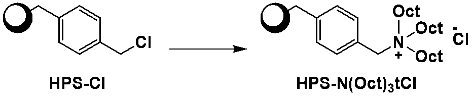
HPS-NOct3Clは、国際公開第2012/141215号に記載された方法に従い、以下のように合成した。
還流塔を付した100mLの反応フラスコに、合成例2-1で製造したHPS-Cl4.6g(30mmol)、トリオクチルアミン[純正化学(株)製]10.6g(30mmol)およびクロロホルム45gを仕込み、窒素置換した。この混合物を、撹拌しながら48時間加熱還流した。
液温30℃まで冷却後、溶媒を留去した。得られた残渣を、クロロホルム150gに溶解し、0℃に冷却した。この溶液を0℃のIPE3,000gに添加して再沈精製した。析出したポリマーを減圧ろ過し、40℃で真空乾燥して、トリオクチルアンモニウム基を分子末端に有するハイパーブランチポリマー(HPS-NOct3Cl)9.6gを淡黄色粉末として得た。
得られたHPS-ClのMw(14,000)およびアンモニウム基導入率(71%)から算出されるHPS-NOct3Clの重量平均分子量Mwは37,000となった。
還流塔を付した100mLの反応フラスコに、合成例2-1で製造したHPS-Cl4.6g(30mmol)、トリオクチルアミン[純正化学(株)製]10.6g(30mmol)およびクロロホルム45gを仕込み、窒素置換した。この混合物を、撹拌しながら48時間加熱還流した。
液温30℃まで冷却後、溶媒を留去した。得られた残渣を、クロロホルム150gに溶解し、0℃に冷却した。この溶液を0℃のIPE3,000gに添加して再沈精製した。析出したポリマーを減圧ろ過し、40℃で真空乾燥して、トリオクチルアンモニウム基を分子末端に有するハイパーブランチポリマー(HPS-NOct3Cl)9.6gを淡黄色粉末として得た。
得られたHPS-ClのMw(14,000)およびアンモニウム基導入率(71%)から算出されるHPS-NOct3Clの重量平均分子量Mwは37,000となった。
[合成例2-5]Pd[HPS-NOct3Cl]の合成
1Lの二つ口フラスコに、酢酸パラジウム[川研ファインケミカル(株)製]4.3gおよびクロロホルム200gを仕込み、均一になるまで撹拌した。この溶液へ、合成例2-4に従って製造したHPS-NOct3Cl18.0gをクロロホルム200gに溶解させた溶液を、滴下ロートを使用して加えた。この滴下ロート内を、エタノール100gを使用して上記反応フラスコへ洗い込んだ。この混合物を60℃で17時間撹拌した。
液温30℃まで冷却後、溶媒を留去した。得られた残渣をTHF300gに溶解し、0℃に冷却した。この溶液を0℃のIPE6,000gに添加して再沈精製した。析出したポリマーを減圧ろ過し、60℃で真空乾燥して、アンモニウム基を分子末端に有するハイパーブランチポリマーとPd粒子の複合体(Pd[HPS-NOct3Cl])19.9gを黒色粉末として得た。
ICP発光分析の結果から、得られたPd[HPS-NOct3Cl]のPd含有量は11質量%であった。また、得られたPd粒子をTEM観察した画像を図6に示す。TEM観察により、Pd粒子径はおよそ2~4nmであった。
1Lの二つ口フラスコに、酢酸パラジウム[川研ファインケミカル(株)製]4.3gおよびクロロホルム200gを仕込み、均一になるまで撹拌した。この溶液へ、合成例2-4に従って製造したHPS-NOct3Cl18.0gをクロロホルム200gに溶解させた溶液を、滴下ロートを使用して加えた。この滴下ロート内を、エタノール100gを使用して上記反応フラスコへ洗い込んだ。この混合物を60℃で17時間撹拌した。
液温30℃まで冷却後、溶媒を留去した。得られた残渣をTHF300gに溶解し、0℃に冷却した。この溶液を0℃のIPE6,000gに添加して再沈精製した。析出したポリマーを減圧ろ過し、60℃で真空乾燥して、アンモニウム基を分子末端に有するハイパーブランチポリマーとPd粒子の複合体(Pd[HPS-NOct3Cl])19.9gを黒色粉末として得た。
ICP発光分析の結果から、得られたPd[HPS-NOct3Cl]のPd含有量は11質量%であった。また、得られたPd粒子をTEM観察した画像を図6に示す。TEM観察により、Pd粒子径はおよそ2~4nmであった。
[3]剥離層形成用組成物の調製
[調製例1-1]剥離層形成用組成物1の調製
合成例1-1で得られたポリウレアを100重量部、PL-LIを32重量部、PPTSを3重量部、フッ素含有ポリマー(S1)を16.8重量部、DIC製「メガファックF-554」を0.5重量部、およびPGMEAを加え、固形分濃度が2質量%、PGMEA濃度が30質量%となるようにPGMEで希釈し、剥離層形成用組成物1を調製した。
[調製例1-1]剥離層形成用組成物1の調製
合成例1-1で得られたポリウレアを100重量部、PL-LIを32重量部、PPTSを3重量部、フッ素含有ポリマー(S1)を16.8重量部、DIC製「メガファックF-554」を0.5重量部、およびPGMEAを加え、固形分濃度が2質量%、PGMEA濃度が30質量%となるようにPGMEで希釈し、剥離層形成用組成物1を調製した。
[調製例1-2]剥離層形成用組成物2の調製
フッ素含有ポリマー(S1)のかわりにフッ素含有ポリマー(S2)を用いた以外は、調製例1-1と同様の方法で剥離層形成用組成物2を得た。
フッ素含有ポリマー(S1)のかわりにフッ素含有ポリマー(S2)を用いた以外は、調製例1-1と同様の方法で剥離層形成用組成物2を得た。
[調製例1-3]剥離層形成用組成物3の調製
フッ素含有ポリマー(S1)のかわりにフッ素含有ポリマー(S3)を用いた以外は、調製例1-1と同様の方法で剥離層形成用組成物3を得た。
フッ素含有ポリマー(S1)のかわりにフッ素含有ポリマー(S3)を用いた以外は、調製例1-1と同様の方法で剥離層形成用組成物3を得た。
[調製例1-4]剥離層形成用組成物4の調製
フッ素含有ポリマー(S1)のかわりにフッ素含有ポリマー(S4)を用いた以外は、調製例1-1と同様の方法で剥離層形成用組成物4を得た。
フッ素含有ポリマー(S1)のかわりにフッ素含有ポリマー(S4)を用いた以外は、調製例1-1と同様の方法で剥離層形成用組成物4を得た。
[調製例1-5]剥離層形成用組成物5の調製
フッ素含有ポリマー(S1)のかわりにフッ素含有ポリマー(S5)を用いた以外は、調製例1-1と同様の方法で剥離層形成用組成物5を得た。
フッ素含有ポリマー(S1)のかわりにフッ素含有ポリマー(S5)を用いた以外は、調製例1-1と同様の方法で剥離層形成用組成物5を得た。
[3] めっき下地剤の調製
[調製例2-1]無電解めっき下地剤1の調製
合成例2-3で製造したPd[HPS-N(Me)2OctCl]75mg、レベリング剤「ポリフローNo.56(共栄社化学製)」2.5mgを、DEGMEE2.46g、IPA2.46gに溶解し、固形分濃度1.5質量%の無電解めっき下地剤1を調製した。
[調製例2-1]無電解めっき下地剤1の調製
合成例2-3で製造したPd[HPS-N(Me)2OctCl]75mg、レベリング剤「ポリフローNo.56(共栄社化学製)」2.5mgを、DEGMEE2.46g、IPA2.46gに溶解し、固形分濃度1.5質量%の無電解めっき下地剤1を調製した。
[調製例2-2]無電解めっき下地剤2の調製
合成例2-5で製造したPd[HPS-NOct3Cl]75mgを、ノルマルプロパノール4.93gに溶解し、固形分濃度1.5質量%の無電解めっき下地剤2を調製した。
合成例2-5で製造したPd[HPS-NOct3Cl]75mgを、ノルマルプロパノール4.93gに溶解し、固形分濃度1.5質量%の無電解めっき下地剤2を調製した。
[4]無電解めっき液の調製
[調製例3]無電解銅めっき液の調製
市販のプリントガント(登録商標)PVG2[アトテックジャパン(株)製]を用いて、以下のように無電解銅めっき液を調製した。
200mLのフラスコに、純水を150mL、ベーシックプリントガントPVG2を28mL、カッパープリントガントPVG2を17mL、モデレータープリントガントPVG2を0.76mL、スタビライザープリントガントPVG2を0.08mL、リデューサーCuを3mL、および10質量%NaOHaq1mLを加え、撹拌して34℃まで昇温し、無電解銅めっき液とした。
[調製例3]無電解銅めっき液の調製
市販のプリントガント(登録商標)PVG2[アトテックジャパン(株)製]を用いて、以下のように無電解銅めっき液を調製した。
200mLのフラスコに、純水を150mL、ベーシックプリントガントPVG2を28mL、カッパープリントガントPVG2を17mL、モデレータープリントガントPVG2を0.76mL、スタビライザープリントガントPVG2を0.08mL、リデューサーCuを3mL、および10質量%NaOHaq1mLを加え、撹拌して34℃まで昇温し、無電解銅めっき液とした。
[5]積層体(支持基材/剥離層/無電解めっき触媒層)の作製
[実施例1-1]
PETフィルム(帝人(株)製「テトロン(登録商標)」(現:東洋紡(株)製「東洋紡エステル(登録商標)フィルム」)HB3)上に剥離層形成用組成物1を膜厚12μmでバーコート塗布し、オーブンを用いて100℃で5分間加熱することにより塗膜を得た。この塗膜をさらにオーブンを用いて150℃で10分間加熱することにより硬化させ、剥離層付きPETフィルムを得た。
その後、上記PETフィルム上の剥離層の上に無電解めっき下地剤1を膜厚6μmでバーコート塗布し、オーブンを用いて150℃で5分間加熱することにより積層体Aを得た。
[実施例1-1]
PETフィルム(帝人(株)製「テトロン(登録商標)」(現:東洋紡(株)製「東洋紡エステル(登録商標)フィルム」)HB3)上に剥離層形成用組成物1を膜厚12μmでバーコート塗布し、オーブンを用いて100℃で5分間加熱することにより塗膜を得た。この塗膜をさらにオーブンを用いて150℃で10分間加熱することにより硬化させ、剥離層付きPETフィルムを得た。
その後、上記PETフィルム上の剥離層の上に無電解めっき下地剤1を膜厚6μmでバーコート塗布し、オーブンを用いて150℃で5分間加熱することにより積層体Aを得た。
[実施例1-2]
ポリイミドフィルム(東レ(株)製「カプトン」300H、厚さ75μm)上に剥離層形成用組成物1を膜厚12μmでバーコート塗布し、オーブンを用いて100℃で5分間加熱することにより塗膜を得た。この塗膜をさらにオーブンを用いて150℃で10分間加熱することにより硬化させ、剥離層付きポリイミドフィルムを得た。
その後、上記ポリイミドフィルム上の剥離層の上に無電解めっき下地剤1を膜厚6μmでバーコート塗布し、オーブンを用いて150℃で5分間加熱することにより塗膜を得た。この塗膜をさらにオーブンを用いて170℃で30分間加熱し、積層体Bを得た。
ポリイミドフィルム(東レ(株)製「カプトン」300H、厚さ75μm)上に剥離層形成用組成物1を膜厚12μmでバーコート塗布し、オーブンを用いて100℃で5分間加熱することにより塗膜を得た。この塗膜をさらにオーブンを用いて150℃で10分間加熱することにより硬化させ、剥離層付きポリイミドフィルムを得た。
その後、上記ポリイミドフィルム上の剥離層の上に無電解めっき下地剤1を膜厚6μmでバーコート塗布し、オーブンを用いて150℃で5分間加熱することにより塗膜を得た。この塗膜をさらにオーブンを用いて170℃で30分間加熱し、積層体Bを得た。
[実施例1-3]
ポリイミドフィルム(東レ(株)製「カプトン」300H、厚さ75μm)上に剥離層形成用組成物2を膜厚12μmでバーコート塗布し、オーブンを用いて100℃で5分間加熱することにより塗膜を得た。この塗膜をさらにオーブンを用いて230℃で10分間加熱することにより硬化させ、剥離層付きポリイミドフィルムを得た。
その後、上記ポリイミドフィルム上の剥離層の上に無電解めっき下地剤2を膜厚6μmでバーコート塗布し、オーブンを用いて150℃で5分間加熱することにより塗膜を得た。この塗膜をさらにオーブンを用いて250℃で30分間加熱し、積層体Cを得た。
ポリイミドフィルム(東レ(株)製「カプトン」300H、厚さ75μm)上に剥離層形成用組成物2を膜厚12μmでバーコート塗布し、オーブンを用いて100℃で5分間加熱することにより塗膜を得た。この塗膜をさらにオーブンを用いて230℃で10分間加熱することにより硬化させ、剥離層付きポリイミドフィルムを得た。
その後、上記ポリイミドフィルム上の剥離層の上に無電解めっき下地剤2を膜厚6μmでバーコート塗布し、オーブンを用いて150℃で5分間加熱することにより塗膜を得た。この塗膜をさらにオーブンを用いて250℃で30分間加熱し、積層体Cを得た。
[実施例1-4]
剥離層形成用組成物2のかわりに剥離層形成用組成物3を用いた以外は、実施例1-3と同様の方法で積層体Dを得た。
剥離層形成用組成物2のかわりに剥離層形成用組成物3を用いた以外は、実施例1-3と同様の方法で積層体Dを得た。
[実施例1-5]
剥離層形成用組成物2のかわりに剥離層形成用組成物4を用いた以外は、実施例1-3と同様の方法で積層体Eを得た。
剥離層形成用組成物2のかわりに剥離層形成用組成物4を用いた以外は、実施例1-3と同様の方法で積層体Eを得た。
[実施例1-6]
剥離層形成用組成物2のかわりに剥離層形成用組成物5を用いた以外は、実施例1-3と同様の方法で積層体Fを得た。
剥離層形成用組成物2のかわりに剥離層形成用組成物5を用いた以外は、実施例1-3と同様の方法で積層体Fを得た。
[比較例1-1]
PETフィルム(帝人(株)製「テトロン(登録商標)」(現:東洋紡(株)製「東洋紡エステル(登録商標)フィルム」)HB3)上に無電解めっき下地剤1を膜厚6μmでバーコート塗布し、オーブンを用いて150℃で5分間加熱することによりめっき触媒層付きプラスチックフィルムaを得た。
PETフィルム(帝人(株)製「テトロン(登録商標)」(現:東洋紡(株)製「東洋紡エステル(登録商標)フィルム」)HB3)上に無電解めっき下地剤1を膜厚6μmでバーコート塗布し、オーブンを用いて150℃で5分間加熱することによりめっき触媒層付きプラスチックフィルムaを得た。
[比較例1-2]
ポリイミドフィルム(東レ(株)製「カプトン」300H、厚さ75μm)上に無電解めっき下地剤1を膜厚6μmでバーコート塗布し、オーブンを用いて150℃で5分間加熱することにより塗膜を得た。この塗膜をさらにオーブンを用いて170℃で30分間加熱し、めっき触媒層付きプラスチックフィルムbを得た。
ポリイミドフィルム(東レ(株)製「カプトン」300H、厚さ75μm)上に無電解めっき下地剤1を膜厚6μmでバーコート塗布し、オーブンを用いて150℃で5分間加熱することにより塗膜を得た。この塗膜をさらにオーブンを用いて170℃で30分間加熱し、めっき触媒層付きプラスチックフィルムbを得た。
[比較例1-3]
ポリイミドフィルム(東レ(株)製「カプトン」300H、厚さ75μm)上に無電解めっき下地剤2を膜厚6μmでバーコート塗布し、オーブンを用いて150℃で5分間加熱することにより塗膜を得た。この塗膜をさらにオーブンを用いて250℃で30分間加熱し、めっき触媒層付きプラスチックフィルムcを得た。
ポリイミドフィルム(東レ(株)製「カプトン」300H、厚さ75μm)上に無電解めっき下地剤2を膜厚6μmでバーコート塗布し、オーブンを用いて150℃で5分間加熱することにより塗膜を得た。この塗膜をさらにオーブンを用いて250℃で30分間加熱し、めっき触媒層付きプラスチックフィルムcを得た。
[6]無電解銅層積層体(支持基材/剥離層/無電解めっき触媒層/無電解銅層)の作製
[実施例2-1]
実施例1-1で作製した積層体1を、調製例3で調製した無電解銅めっき液中に10分間浸漬した。基材を取り出して水洗し、120℃のホットプレートで10分間乾燥することで無電解銅層積層体Aを得た。
[実施例2-1]
実施例1-1で作製した積層体1を、調製例3で調製した無電解銅めっき液中に10分間浸漬した。基材を取り出して水洗し、120℃のホットプレートで10分間乾燥することで無電解銅層積層体Aを得た。
[実施例2-2]
積層体Aのかわりに積層体Bを用いた以外は、実施例2-1と同様の方法で無電解銅層積層体Bを得た。
積層体Aのかわりに積層体Bを用いた以外は、実施例2-1と同様の方法で無電解銅層積層体Bを得た。
[実施例2-3]
積層体Aのかわりに積層体Cを用いた以外は、実施例2-1と同様の方法で無電解銅層積層体Cを得た。
積層体Aのかわりに積層体Cを用いた以外は、実施例2-1と同様の方法で無電解銅層積層体Cを得た。
[実施例2-4]
積層体Aのかわりに積層体Dを用いた以外は、実施例2-1と同様の方法で無電解銅層積層体Dを得た。
積層体Aのかわりに積層体Dを用いた以外は、実施例2-1と同様の方法で無電解銅層積層体Dを得た。
[実施例2-5]
積層体Aのかわりに積層体Eを用いた以外は、実施例2-1と同様の方法で無電解銅層積層体Eを得た。
積層体Aのかわりに積層体Eを用いた以外は、実施例2-1と同様の方法で無電解銅層積層体Eを得た。
[実施例2-6]
積層体Aのかわりに積層体Fを用いた以外は、実施例2-1と同様の方法で無電解銅層積層体Fを得た。
積層体Aのかわりに積層体Fを用いた以外は、実施例2-1と同様の方法で無電解銅層積層体Fを得た。
[比較例2-1]
積層体Aのかわりにめっき触媒層付きプラスチックフィルムaを用いた以外は、実施例2-1と同様の方法で無電解銅層積層体aを得た。
積層体Aのかわりにめっき触媒層付きプラスチックフィルムaを用いた以外は、実施例2-1と同様の方法で無電解銅層積層体aを得た。
[比較例2-2]
積層体Aのかわりにめっき触媒層付きプラスチックフィルムbを用いた以外は、実施例2-1と同様の方法で無電解銅層積層体bを得た。
積層体Aのかわりにめっき触媒層付きプラスチックフィルムbを用いた以外は、実施例2-1と同様の方法で無電解銅層積層体bを得た。
[比較例2-3]
積層体Aのかわりにめっき触媒層付きプラスチックフィルムcを用いた以外は、実施例2-1と同様の方法で無電解銅層積層体cを得た。
積層体Aのかわりにめっき触媒層付きプラスチックフィルムcを用いた以外は、実施例2-1と同様の方法で無電解銅層積層体cを得た。
[6]無電解銅層の剥離力評価
無電解銅層積層体A~Fおよびa~cに、セロテープ(登録商標)(ニチバン(株)製CT-24)を貼り、これを上記装置で剥離することで剥離力を測定した。なお剥離できないものは、剥離不可とした。結果を表1に示す。
無電解銅層積層体A~Fおよびa~cに、セロテープ(登録商標)(ニチバン(株)製CT-24)を貼り、これを上記装置で剥離することで剥離力を測定した。なお剥離できないものは、剥離不可とした。結果を表1に示す。
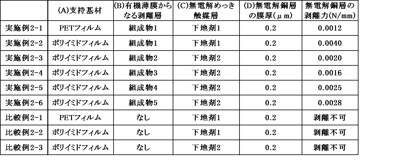
さらに実施例2-3で得られた無電解銅層積層体Cを240℃のホットプレート上で窒素フローしながら30分間加熱した後の剥離力を評価すると、0.0017N/mmとなり高温焼成工程を追加しても無電解銅層の剥離力は維持された。
表1に示した実施例の無電解銅層の剥離面を観察すると、無電解銅層側は黒色のパラジウム粒子の付着が見られるが、支持基材側には上記付着物が見られなかった。この結果より、剥離界面は有機薄膜からなる剥離層と無電解めっき触媒層の界面となっていることが推察される。
上記の結果より、実施例の剥離層は、支持基材との密着性に優れ、かつ無電解めっき触媒層との剥離性に優れていた。一方、比較例の剥離層を形成しない無電解銅層積層体a~cでは無電解銅層を支持基材から剥離することができなかった。表1に示した実施例の無電解銅層から支持基材を剥離した後、得られたプリント配線基板用シード層側の剥離面を奥野製薬(株)製OPCパラクリーンによる脱脂処理をした。次いで、該シード層を奥野製薬(株)製パラジウムエッチング液OPCパラデリートに浸漬したところ、剥離面がパラジウムの黒色から銅光沢色へと変化した。このことから、無電解めっき触媒層が除去され、無電解銅層が露出したと推察される。以上より、無電解めっき触媒層を残したまま次の工程で使用することもできるし、無電解めっき触媒層を除去してから使用することもできる。
1 積層体(無電解銅層積層体)
10 積層体
11 支持基材
12 有機薄膜からなる剥離層
13 無電解めっき触媒層
14 無電解銅層
2 樹脂基板
3 フォトレジスト層
4 配線パターン
S プリント配線基板用シード層
P プリント配線基板
10 積層体
11 支持基材
12 有機薄膜からなる剥離層
13 無電解めっき触媒層
14 無電解銅層
2 樹脂基板
3 フォトレジスト層
4 配線パターン
S プリント配線基板用シード層
P プリント配線基板
Claims (21)
- (A)支持基材と、(B)有機薄膜からなる剥離層と、(C)無電解めっき触媒層とが順番に積層された積層体。
- さらに、上記(C)無電解めっき触媒層の上に(D)無電解銅層が積層された請求項1記載の積層体。
- 上記(A)支持基材が、プラスチック支持基材である請求項2記載の積層体。
- 上記(B)有機薄膜からなる剥離層が、フッ素含有ポリマーおよび熱硬化性樹脂を含有する剥離層形成用組成物から得られる剥離層である請求項2記載の積層体。
- 上記熱硬化性樹脂が、ポリウレアおよび架橋剤からなる請求項4記載の積層体。
- 上記ポリウレアが、下記式(U1)で表される繰り返し単位を含む請求項5記載の積層体。

Xu1は、下記式(U1-1)、(U1-2)、(U1-3)または(U1-4)で表される基であり、

Qu1は、下記式(U1-5)または(U1-6)で表される基である。
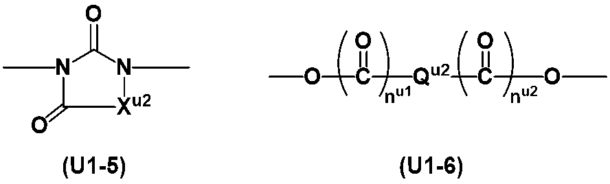
- 上記フッ素含有ポリマーが、下記式(a1)で表される繰り返し単位、下記式(b)で表される繰り返し単位および下記式(c)で表される繰り返し単位を含むポリマーである請求項4記載の積層体。

- 上記(C)無電解めっき触媒層が、アルコキシ基、ヒドロキシ基、アンモニウム基、カルボキシ基またはシアノ基を有するポリマーと金属微粒子とを含有する請求項2記載の積層体。
- 上記金属微粒子が、パラジウム微粒子である請求項8記載の積層体。
- 上記ポリマーが、ハイパーブランチポリマーである請求項8記載の積層体。
- 上記ハイパーブランチポリマーが、重量平均分子量が500~5,000,000である、式[1]で表されるハイパーブランチポリマーである請求項10記載の積層体。
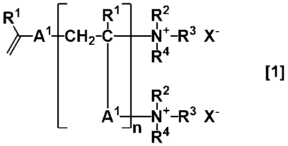
R2、R3およびR4は、それぞれ独立して、水素原子、炭素数1~20の直鎖状、分岐状もしくは環状のアルキル基、炭素数7~20のアリールアルキル基、または-(CH2CH2O)mR5(式中、R5は、水素原子またはメチル基を表し、mは、2~100の整数を表す。)であり、
上記アルキル基およびアリールアルキル基は、アルコキシ基、ヒドロキシ基、アンモニウム基、カルボキシ基またはシアノ基で置換されていてもよく、
上記R2、R3およびR4のうちの2つの基が一緒になって、直鎖状、分岐状もしくは環状のアルキレン基を表すか、またはR2、R3およびR4ならびにこれらが結合する窒素原子とともに環を形成してもよく、
X-は、陰イオンであり、
nは、2~100,000の整数であり
A1は、下記式[2]で表される構造である。
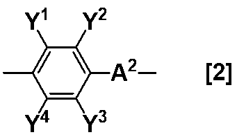
Y1、Y2、Y3およびY4は、それぞれ独立して、水素原子、炭素数1~20のアルキル基、炭素数1~20のアルコキシ基、ニトロ基、ヒドロキシ基、アミノ基、カルボキシル基またはシアノ基である。)] - 上記金属微粒子と、上記ハイパーブランチポリマーとが複合体を形成している請求項10記載の積層体。
- 上記ハイパーブランチポリマーが、重量平均分子量が500~5,000,000である、式[3]で表されるハイパーブランチポリマーである請求項10記載の積層体。
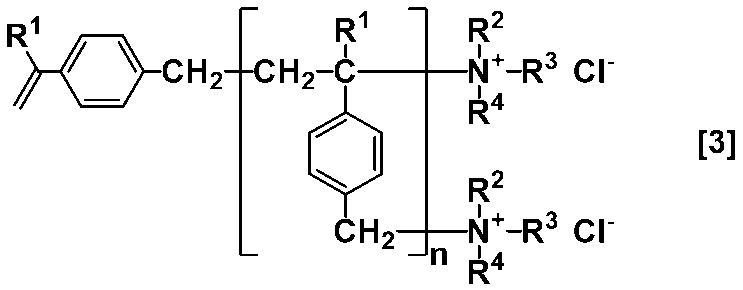
- (A)支持基材上に(B)有機薄膜からなる剥離層を成膜する工程、および
(B)有機薄膜からなる剥離層上に(C)無電解めっき触媒層を成膜する工程
を含む請求項2~13のいずれか1項記載の積層体の製造方法。 - さらに、(C)無電解めっき触媒層上に(D)無電解銅層を形成する工程を含む請求項14記載の積層体の製造方法。
- 請求項2~13のいずれか1項記載の積層体の(D)無電解銅層を樹脂基板に圧着し、(A)支持基材を剥離して、上記(D)無電解銅層を上記樹脂基板側に転写するプリント配線基板用シード層の製造方法。
- 請求項2~13のいずれかの積層体の(D)無電解銅層を樹脂基板に圧着し、(A)支持基材を剥離して、上記(D)無電解銅層を上記樹脂基板に転写した後、パラジウムエッチング液で(C)無電解めっき触媒層を除去するプリント配線基板用シード層の製造方法。
- 上記(A)支持基材を剥離する際、(B)有機薄膜からなる剥離層と(C)無電解めっき触媒層の界面で剥離する、請求項16記載のプリント配線基板用シード層の製造方法。
- 請求項16記載のプリント配線基板用シード層を用いるプリント配線基板の製造方法。
- 上記(A)支持基材を剥離する際、(B)有機薄膜からなる剥離層と(C)無電解めっき触媒層の界面で剥離する、請求項17記載のプリント配線基板用シード層の製造方法。
- 請求項17記載のプリント配線基板用シード層を用いるプリント配線基板の製造方法。
Priority Applications (3)
| Application Number | Priority Date | Filing Date | Title |
|---|---|---|---|
| CN202480033662.0A CN121175187A (zh) | 2023-05-31 | 2024-05-10 | 层叠体 |
| KR1020257038281A KR20260018806A (ko) | 2023-05-31 | 2024-05-10 | 적층체 |
| JP2025523415A JPWO2024247656A1 (ja) | 2023-05-31 | 2024-05-10 |
Applications Claiming Priority (2)
| Application Number | Priority Date | Filing Date | Title |
|---|---|---|---|
| JP2023-090041 | 2023-05-31 | ||
| JP2023090041 | 2023-05-31 |
Publications (1)
| Publication Number | Publication Date |
|---|---|
| WO2024247656A1 true WO2024247656A1 (ja) | 2024-12-05 |
Family
ID=93657276
Family Applications (1)
| Application Number | Title | Priority Date | Filing Date |
|---|---|---|---|
| PCT/JP2024/017383 Ceased WO2024247656A1 (ja) | 2023-05-31 | 2024-05-10 | 積層体 |
Country Status (5)
| Country | Link |
|---|---|
| JP (1) | JPWO2024247656A1 (ja) |
| KR (1) | KR20260018806A (ja) |
| CN (1) | CN121175187A (ja) |
| TW (1) | TW202508826A (ja) |
| WO (1) | WO2024247656A1 (ja) |
Citations (9)
| Publication number | Priority date | Publication date | Assignee | Title |
|---|---|---|---|---|
| JP2003198183A (ja) * | 2001-12-25 | 2003-07-11 | Dainippon Printing Co Ltd | 電磁波遮蔽シートの製造方法及び電磁波遮蔽シート |
| WO2005098542A1 (ja) * | 2004-04-09 | 2005-10-20 | Nissan Chemical Industries, Ltd. | 縮合系ポリマーを有する半導体用反射防止膜 |
| JP2006240222A (ja) * | 2005-03-07 | 2006-09-14 | Tokyo Institute Of Technology | 金属被覆物、金属配線基板及びそれらの製造方法 |
| JP2008177490A (ja) * | 2007-01-22 | 2008-07-31 | Seiko Epson Corp | 素子基板の製造方法 |
| WO2012141215A1 (ja) * | 2011-04-12 | 2012-10-18 | 日産化学工業株式会社 | ハイパーブランチポリマー及び金属微粒子を含む無電解めっき下地剤 |
| JP2013227637A (ja) * | 2012-04-27 | 2013-11-07 | Seiren Co Ltd | キャリア付き穴開き金属箔およびその製造方法 |
| KR20160001826A (ko) * | 2014-06-27 | 2016-01-07 | 대덕전자 주식회사 | 인쇄회로기판 제조방법 |
| JP2016211028A (ja) * | 2015-05-01 | 2016-12-15 | 株式会社イオックス | 無電解めっき用転写フィルム用触媒組成物及び無電解めっき用転写フィルム |
| JP2020090717A (ja) * | 2018-12-07 | 2020-06-11 | 株式会社イオックス | 無電解めっき用真空転写フィルム |
Family Cites Families (4)
| Publication number | Priority date | Publication date | Assignee | Title |
|---|---|---|---|---|
| JPH08158027A (ja) | 1994-12-05 | 1996-06-18 | Nippon Foil Mfg Co Ltd | 圧延銅箔の焼鈍方法 |
| JP3295308B2 (ja) | 1996-06-28 | 2002-06-24 | 株式会社日鉱マテリアルズ | 電解銅箔 |
| US7026059B2 (en) | 2000-09-22 | 2006-04-11 | Circuit Foil Japan Co., Ltd. | Copper foil for high-density ultrafine printed wiring boad |
| US6893742B2 (en) | 2001-02-15 | 2005-05-17 | Olin Corporation | Copper foil with low profile bond enhancement |
-
2024
- 2024-05-10 CN CN202480033662.0A patent/CN121175187A/zh active Pending
- 2024-05-10 WO PCT/JP2024/017383 patent/WO2024247656A1/ja not_active Ceased
- 2024-05-10 KR KR1020257038281A patent/KR20260018806A/ko active Pending
- 2024-05-10 JP JP2025523415A patent/JPWO2024247656A1/ja active Pending
- 2024-05-20 TW TW113118607A patent/TW202508826A/zh unknown
Patent Citations (9)
| Publication number | Priority date | Publication date | Assignee | Title |
|---|---|---|---|---|
| JP2003198183A (ja) * | 2001-12-25 | 2003-07-11 | Dainippon Printing Co Ltd | 電磁波遮蔽シートの製造方法及び電磁波遮蔽シート |
| WO2005098542A1 (ja) * | 2004-04-09 | 2005-10-20 | Nissan Chemical Industries, Ltd. | 縮合系ポリマーを有する半導体用反射防止膜 |
| JP2006240222A (ja) * | 2005-03-07 | 2006-09-14 | Tokyo Institute Of Technology | 金属被覆物、金属配線基板及びそれらの製造方法 |
| JP2008177490A (ja) * | 2007-01-22 | 2008-07-31 | Seiko Epson Corp | 素子基板の製造方法 |
| WO2012141215A1 (ja) * | 2011-04-12 | 2012-10-18 | 日産化学工業株式会社 | ハイパーブランチポリマー及び金属微粒子を含む無電解めっき下地剤 |
| JP2013227637A (ja) * | 2012-04-27 | 2013-11-07 | Seiren Co Ltd | キャリア付き穴開き金属箔およびその製造方法 |
| KR20160001826A (ko) * | 2014-06-27 | 2016-01-07 | 대덕전자 주식회사 | 인쇄회로기판 제조방법 |
| JP2016211028A (ja) * | 2015-05-01 | 2016-12-15 | 株式会社イオックス | 無電解めっき用転写フィルム用触媒組成物及び無電解めっき用転写フィルム |
| JP2020090717A (ja) * | 2018-12-07 | 2020-06-11 | 株式会社イオックス | 無電解めっき用真空転写フィルム |
Also Published As
| Publication number | Publication date |
|---|---|
| CN121175187A (zh) | 2025-12-19 |
| TW202508826A (zh) | 2025-03-01 |
| JPWO2024247656A1 (ja) | 2024-12-05 |
| KR20260018806A (ko) | 2026-02-09 |
Similar Documents
| Publication | Publication Date | Title |
|---|---|---|
| EP3919531B1 (en) | Resin composition, resin sheet, multilayer printed wiring board, and semiconductor device | |
| JP5258489B2 (ja) | 金属膜形成方法 | |
| US20100116532A1 (en) | Photosensitive resin composition, dry film, and processed product made using the same | |
| US20110226511A1 (en) | Inkjet ink, surface metal film material and its manufacturing method, and patterned metal material and its manufacturing method | |
| JP6021804B2 (ja) | ハイパーブランチポリマー、金属微粒子及び有機酸を含む無電解めっき下地剤 | |
| TW201516087A (zh) | 感光性樹脂組成物 | |
| JP7702778B2 (ja) | 樹脂組成物 | |
| CN108884568B (zh) | 导电性层叠体的制造方法、层叠体及导电性层叠体 | |
| WO2014042215A1 (ja) | 無電解めっき下地剤 | |
| WO2012141215A1 (ja) | ハイパーブランチポリマー及び金属微粒子を含む無電解めっき下地剤 | |
| TWI683866B (zh) | 感光性無電解鍍敷底塗劑 | |
| CN101911844A (zh) | 覆有金属箔的基板及其制造方法 | |
| WO2016017625A1 (ja) | ハイパーブランチポリマー、金属微粒子及び樹脂プライマーを含む無電解めっき下地剤 | |
| JP7847136B2 (ja) | 誘電体膜形成組成物 | |
| US12338309B2 (en) | Dielectric film-forming composition | |
| JP2022077908A (ja) | 樹脂組成物 | |
| TW201708607A (zh) | 感光性無電解鍍敷基底劑 | |
| TW202508826A (zh) | 積層體 | |
| WO2019171985A1 (ja) | 高分子及び金属微粒子を含む無電解めっき下地剤 | |
| WO2012133032A1 (ja) | パターン状金属膜を有する積層体の製造方法、被めっき層形成用組成物 | |
| JP2012031447A (ja) | 被めっき層形成用組成物、表面金属膜材料およびその製造方法、並びに、金属パターン材料およびその製造方法 | |
| TW201132795A (en) | Method of plate pretreatment and production method of surface metal film material | |
| KR20250134035A (ko) | 감광성 수지 조성물 | |
| JP7139131B2 (ja) | 無電解メッキ用硬化物形成用組成物、無電解メッキ用硬化物、無電解メッキ用硬化物の製造方法、配線基板、及び配線基板の製造方法 | |
| CN121203125A (zh) | 一种碱溶性感光树脂及感光树脂组合物 |
Legal Events
| Date | Code | Title | Description |
|---|---|---|---|
| 121 | Ep: the epo has been informed by wipo that ep was designated in this application |
Ref document number: 24815140 Country of ref document: EP Kind code of ref document: A1 |
|
| ENP | Entry into the national phase |
Ref document number: 2025523415 Country of ref document: JP Kind code of ref document: A |
|
| WWE | Wipo information: entry into national phase |
Ref document number: 2025523415 Country of ref document: JP |
|
| NENP | Non-entry into the national phase |
Ref country code: DE |