WO2024247213A1 - 熱交換器及び空気調和装置 - Google Patents
熱交換器及び空気調和装置 Download PDFInfo
- Publication number
- WO2024247213A1 WO2024247213A1 PCT/JP2023/020444 JP2023020444W WO2024247213A1 WO 2024247213 A1 WO2024247213 A1 WO 2024247213A1 JP 2023020444 W JP2023020444 W JP 2023020444W WO 2024247213 A1 WO2024247213 A1 WO 2024247213A1
- Authority
- WO
- WIPO (PCT)
- Prior art keywords
- heat transfer
- heat exchanger
- refrigerant
- transfer tubes
- heat
- Prior art date
- Legal status (The legal status is an assumption and is not a legal conclusion. Google has not performed a legal analysis and makes no representation as to the accuracy of the status listed.)
- Ceased
Links
Images






Classifications
-
- F—MECHANICAL ENGINEERING; LIGHTING; HEATING; WEAPONS; BLASTING
- F28—HEAT EXCHANGE IN GENERAL
- F28D—HEAT-EXCHANGE APPARATUS, NOT PROVIDED FOR IN ANOTHER SUBCLASS, IN WHICH THE HEAT-EXCHANGE MEDIA DO NOT COME INTO DIRECT CONTACT
- F28D1/00—Heat-exchange apparatus having stationary conduit assemblies for one heat-exchange medium only, the media being in contact with different sides of the conduit wall, in which the other heat-exchange medium is a large body of fluid, e.g. domestic or motor car radiators
- F28D1/02—Heat-exchange apparatus having stationary conduit assemblies for one heat-exchange medium only, the media being in contact with different sides of the conduit wall, in which the other heat-exchange medium is a large body of fluid, e.g. domestic or motor car radiators with heat-exchange conduits immersed in the body of fluid
- F28D1/03—Heat-exchange apparatus having stationary conduit assemblies for one heat-exchange medium only, the media being in contact with different sides of the conduit wall, in which the other heat-exchange medium is a large body of fluid, e.g. domestic or motor car radiators with heat-exchange conduits immersed in the body of fluid with plate-like or laminated conduits
-
- F—MECHANICAL ENGINEERING; LIGHTING; HEATING; WEAPONS; BLASTING
- F28—HEAT EXCHANGE IN GENERAL
- F28D—HEAT-EXCHANGE APPARATUS, NOT PROVIDED FOR IN ANOTHER SUBCLASS, IN WHICH THE HEAT-EXCHANGE MEDIA DO NOT COME INTO DIRECT CONTACT
- F28D1/00—Heat-exchange apparatus having stationary conduit assemblies for one heat-exchange medium only, the media being in contact with different sides of the conduit wall, in which the other heat-exchange medium is a large body of fluid, e.g. domestic or motor car radiators
- F28D1/02—Heat-exchange apparatus having stationary conduit assemblies for one heat-exchange medium only, the media being in contact with different sides of the conduit wall, in which the other heat-exchange medium is a large body of fluid, e.g. domestic or motor car radiators with heat-exchange conduits immersed in the body of fluid
- F28D1/04—Heat-exchange apparatus having stationary conduit assemblies for one heat-exchange medium only, the media being in contact with different sides of the conduit wall, in which the other heat-exchange medium is a large body of fluid, e.g. domestic or motor car radiators with heat-exchange conduits immersed in the body of fluid with tubular conduits
-
- F—MECHANICAL ENGINEERING; LIGHTING; HEATING; WEAPONS; BLASTING
- F28—HEAT EXCHANGE IN GENERAL
- F28D—HEAT-EXCHANGE APPARATUS, NOT PROVIDED FOR IN ANOTHER SUBCLASS, IN WHICH THE HEAT-EXCHANGE MEDIA DO NOT COME INTO DIRECT CONTACT
- F28D7/00—Heat-exchange apparatus having stationary tubular conduit assemblies for both heat-exchange media, the media being in contact with different sides of a conduit wall
- F28D7/10—Heat-exchange apparatus having stationary tubular conduit assemblies for both heat-exchange media, the media being in contact with different sides of a conduit wall the conduits being arranged one within the other, e.g. concentrically
-
- F—MECHANICAL ENGINEERING; LIGHTING; HEATING; WEAPONS; BLASTING
- F28—HEAT EXCHANGE IN GENERAL
- F28F—DETAILS OF HEAT-EXCHANGE AND HEAT-TRANSFER APPARATUS, OF GENERAL APPLICATION
- F28F1/00—Tubular elements; Assemblies of tubular elements
- F28F1/02—Tubular elements of cross-section which is non-circular
-
- F—MECHANICAL ENGINEERING; LIGHTING; HEATING; WEAPONS; BLASTING
- F28—HEAT EXCHANGE IN GENERAL
- F28F—DETAILS OF HEAT-EXCHANGE AND HEAT-TRANSFER APPARATUS, OF GENERAL APPLICATION
- F28F1/00—Tubular elements; Assemblies of tubular elements
- F28F1/02—Tubular elements of cross-section which is non-circular
- F28F1/04—Tubular elements of cross-section which is non-circular polygonal, e.g. rectangular
-
- F—MECHANICAL ENGINEERING; LIGHTING; HEATING; WEAPONS; BLASTING
- F28—HEAT EXCHANGE IN GENERAL
- F28F—DETAILS OF HEAT-EXCHANGE AND HEAT-TRANSFER APPARATUS, OF GENERAL APPLICATION
- F28F3/00—Plate-like or laminated elements; Assemblies of plate-like or laminated elements
- F28F3/08—Elements constructed for building-up into stacks, e.g. capable of being taken apart for cleaning
-
- F—MECHANICAL ENGINEERING; LIGHTING; HEATING; WEAPONS; BLASTING
- F28—HEAT EXCHANGE IN GENERAL
- F28F—DETAILS OF HEAT-EXCHANGE AND HEAT-TRANSFER APPARATUS, OF GENERAL APPLICATION
- F28F9/00—Casings; Header boxes; Auxiliary supports for elements; Auxiliary members within casings
- F28F9/02—Header boxes; End plates
-
- F—MECHANICAL ENGINEERING; LIGHTING; HEATING; WEAPONS; BLASTING
- F28—HEAT EXCHANGE IN GENERAL
- F28F—DETAILS OF HEAT-EXCHANGE AND HEAT-TRANSFER APPARATUS, OF GENERAL APPLICATION
- F28F9/00—Casings; Header boxes; Auxiliary supports for elements; Auxiliary members within casings
- F28F9/22—Arrangements for directing heat-exchange media into successive compartments, e.g. arrangements of guide plates
-
- F—MECHANICAL ENGINEERING; LIGHTING; HEATING; WEAPONS; BLASTING
- F28—HEAT EXCHANGE IN GENERAL
- F28F—DETAILS OF HEAT-EXCHANGE AND HEAT-TRANSFER APPARATUS, OF GENERAL APPLICATION
- F28F9/00—Casings; Header boxes; Auxiliary supports for elements; Auxiliary members within casings
- F28F9/26—Arrangements for connecting different sections of heat-exchange elements, e.g. of radiators
Definitions
- This disclosure relates to a heat exchanger and an air conditioning device equipped with this heat exchanger.
- fin-tube heat exchangers in which heat transfer tubes penetrate the fins, have been used for heat exchangers.
- Fin-tube heat exchangers have been designed to improve heat exchange efficiency and reduce size by reducing the diameter of the heat transfer tubes, but structural difficulties have also limited this.
- plate-fin stacked heat exchangers can have a smaller cross-sectional area of the heat transfer flow path than fin-tube heat transfer tubes, improving heat exchange efficiency and allowing for size reduction.
- heat exchangers have been proposed that incorporate functions such as an internal heat exchanger (HIC: Heat Inter Changer) or gas-liquid separation into the conventional heat exchangers (see, for example, Patent Document 1).
- HIC Heat Inter Changer
- the heat exchanger of Patent Document 1 realizes an internal heat exchanger by processing the header portion, but processing the header portion leads to an increase in size of the header portion, and there is a risk that the heat exchanger will be larger than a heat exchanger that does not have a processed header portion.
- the present disclosure is intended to solve the problems described above, and aims to provide a heat exchanger and air conditioner that are compact while improving heat exchange efficiency.
- the heat exchanger includes a plurality of heat transfer tubes arranged in a first direction, each extending in a second direction intersecting the first direction, both ends in the second direction sealed, and through which a refrigerant flows in the second direction; and a pipe penetrating the plurality of heat transfer tubes in the first direction, through which a refrigerant flows.
- Each of the plurality of heat transfer tubes has a plurality of first through holes formed inside the both ends in the second direction and connecting the internal space of each of the plurality of heat transfer tubes to the outside, and a pair of second through holes formed to face each other in the first direction.
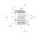
- FIG. 1 is a perspective view showing a schematic configuration of a heat exchanger according to a first embodiment
- 1 is a vertical cross-sectional view of a heat exchanger according to a first embodiment of the present invention
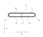
- 2 is a view of a heat transfer tube of the heat exchanger according to the first embodiment viewed in a first direction.
- FIG. 4 is a conceptual diagram of a cross section of the heat transfer tube of FIG. 3 taken along line AA in the heat exchanger according to the first embodiment, as viewed in the direction of the arrows.
- FIG. 4 is a vertical cross-sectional view of a modified example of the heat exchanger according to the first embodiment.
- FIG. 13 is a view of a heat transfer tube of a modified example in the heat exchanger according to the first embodiment, viewed in a first direction.
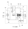
- FIG. 1 is a refrigerant circuit diagram during cooling operation of an air-conditioning apparatus equipped with a heat exchanger according to a first embodiment.
- FIG. 1 is a refrigerant circuit diagram during defrost operation of an air conditioner equipped with a heat exchanger according to Embodiment 1.
- FIG. 4 is another refrigerant circuit diagram during defrost operation of the air conditioner equipped with the heat exchanger according to the first embodiment.
- FIG. 1 is a refrigerant circuit diagram during heating operation of an air conditioner equipped with a heat exchanger according to a first embodiment.
- FIG. 11 is a perspective view showing a schematic configuration of a heat exchanger according to a second embodiment.
- FIG. 11 is a vertical cross-sectional view of a modified example of the heat exchanger according to the second embodiment.
- FIG. 11 is a refrigerant circuit diagram during heating operation of an air conditioner equipped with a heat exchanger according to a second embodiment.
- FIG. 1 is a perspective view showing a schematic configuration of a heat exchanger 100 according to the first embodiment.
- the white arrows shown in Fig. 1 indicate an example of a refrigerant flow direction.
- the configuration of the heat exchanger 100 will be described with reference to Fig. 1.
- the refrigerant flow direction shown by the white arrows below is an example, and the refrigerant flow direction may be opposite to that shown in the figure depending on the case where the heat exchanger 100 functions as an evaporator or a condenser.
- Heat exchanger 100 is a device that exchanges heat between the refrigerant flowing inside heat exchanger 100 and the fluid flowing outside heat exchanger 100. In the case of an air conditioning device, heat exchanger 100 exchanges heat between the refrigerant flowing inside heat exchanger 100 and the air flowing outside heat exchanger 100. Heat exchanger 100 is connected to other heat exchangers and compressors, etc. by refrigerant piping, and constitutes part of the various devices that make up the refrigerant circuit.
- FIG. 2 is a vertical cross-sectional view of the heat exchanger 100 according to the first embodiment.
- FIG. 3 is a view of the heat transfer tube 10 of the heat exchanger 100 according to the first embodiment in the first direction D1.
- FIG. 4 is a conceptual diagram of the heat exchanger 100 according to the first embodiment, in which the cross section of the heat transfer tube 10 in FIG. 3 at the line A-A is viewed in the direction of the arrows.
- the cross-sectional view shown in FIG. 2 shows the cross section of the heat exchanger 100 in a plane along the first direction D1 and the second direction D2.
- FIG. 2 also shows a part of the heat exchanger 100.
- a part of the second direction D2 is omitted from the illustration.
- FIG. 1 and FIG. 2 the direction of the refrigerant flow when the heat exchanger 100 is used as an outdoor heat exchanger described later is indicated by a solid white arrow.
- the heat exchanger 100 includes a plurality of heat transfer tubes 10 arranged in a first direction D1, each extending in a second direction D2 intersecting the first direction D1, sealed at both ends in the second direction D2, through which a refrigerant flows in the second direction D2.
- the heat exchanger 100 also includes a pipe 70 that passes through the plurality of heat transfer tubes 10 in the first direction D1, through which a refrigerant flows.
- the heat exchanger 100 has a plurality of heat transfer tubes 10 arranged in a first direction D1 and connected to each other.
- the heat transfer tubes 10 are flat tubes that extend in a direction in which a tube axis Ax extends (hereinafter also referred to as a tube axis direction) and have a flat shape that is long in one direction in a cross section perpendicular to the tube axis Ax.
- the heat transfer tubes 10 are preferably flat tubes, but are not limited to flat tubes.
- the first direction D1 in which the multiple heat transfer tubes 10 are arranged is referred to as the arrangement direction
- the axial direction of the heat transfer tubes 10 is referred to as the second direction D2 or the longitudinal direction of the heat transfer tubes 10
- the longitudinal direction of the cross section of the heat transfer tubes 10 is referred to as the third direction D3 or the short side direction of the heat transfer tubes 10.
- the third direction D3 is a direction perpendicular to the first direction D1 and the second direction D2.
- the heat exchanger 100 is defined as being installed so that the arrangement direction (first direction D1) of the heat transfer tubes 10 is the left-right direction, as shown in Figure 1.
- Each heat transfer tube 10 is defined as being arranged so that its tube axis Ax is the up-down direction perpendicular to the arrangement direction (first direction D1) and its short side direction (third direction D3) is the front-rear direction perpendicular to the tube axis direction and the arrangement direction.
- the arrangement of the heat exchanger 100, or the angle between the arrangement direction (first direction D1) of the heat transfer tubes 10 in the heat exchanger 100 and the tube axis direction (second direction D2) of each heat transfer tube 10, is not limited to the above case.
- the heat exchanger 100 may be arranged at an angle so that the tube axis direction of each heat transfer tube 10 is inclined with respect to the vertical direction.
- the heat exchanger 100 when the heat exchanger 100 is installed so that the arrangement direction (first direction D1) of the heat transfer tubes 10 is the left-right direction, the heat exchanger 100 may be configured so that the tube axis direction of each heat transfer tube 10 is inclined with respect to the vertical direction.
- Gaps that are air flow paths P2 are formed between the tube walls 11 of adjacent heat transfer tubes 10 in the arrangement direction of the heat transfer tubes 10 (first direction D1), and air flows through each gap in the heat exchanger 100 along the short side direction of the heat transfer tube 10 (third direction D3).
- the fluid that flows through the heat transfer tube 10 is a refrigerant.
- a heat transfer flow path P1a through which the refrigerant flows is provided inside the heat transfer tube 10.
- the fluid that flows through the heat transfer tube 10 may be other fluids such as water or brine instead of a refrigerant.
- the heat exchanger 100 has tube sealing portions 20 that close each open end 10e on both sides in the longitudinal direction (second direction D2) of the heat transfer tubes 10.
- the tube sealing portions 20 are provided for each heat transfer tube 10 at two locations, on the upper and lower sides of the flat tube.
- the tube sealing portions 20 are joined to the open end 10e of the heat transfer tube 10 by a joining means such as brazing or adhesive, for example.
- each of the heat transfer tubes 10 has a tube wall 11 in which a heat transfer flow path P1a is provided, through which a fluid flows in the internal space.
- the heat transfer tube 10 has a tube structure that maintains an internal space through which the refrigerant flows along its longitudinal direction (second direction D2), i.e., from the upper end to the lower end of the tube wall 11.
- the tube wall 11 of the heat transfer tube 10 has substantially flat tube side wall portions 10a and 10b that face each other in the first direction D1.
- the tube wall 11 of the heat transfer tube 10 also has curved connecting wall portions 10c and 10d that connect the tube side wall portions 10a and 10b at each end on both sides of the tube side wall portions 10a and 10b in the third direction D3.
- the tube side wall portions 10a and 10b may be referred to as the tube side wall portions 10a, etc.
- the tube side wall 10a and the tube side wall 10b each have a rectangular shape with a long side extending in the longitudinal direction (second direction D2) of the heat transfer tube 10 and a short side extending in the lateral direction (third direction D3) of the heat transfer tube 10.
- the tube side wall 10a and the tube side wall 10b are each flat, but the "flat" in this application does not have to be a completely flat surface, and may have a structure that appears to spread out in a plane as a whole.
- the tube side wall 10a and the tube side wall 10b may have a depression, protrusion, or wave shape formed in a part of the area that spreads out in a plane.
- the wall on the left side of the tube wall 11 is the tube side wall 10a, and the wall on the right side of the tube wall 11 is the tube side wall 10b. If the heat transfer tube 10 is a circular tube, the tube wall 11 is formed in a cylindrical shape.
- each of the heat transfer tubes 10 is formed with a plurality of first through holes 30 that are formed inward from both ends in the second direction D2 and connect the internal space of each of the heat transfer tubes 10 to the outside.
- each of the heat transfer tubes 10 is formed with a pair of second through holes 40 that are formed to face each other in the first direction D1.
- a first through hole 30 is formed in the tube side wall portion 10a and the tube side wall portion 10b.
- the left tube side wall portion 10a is formed with a first through hole 30a and a first through hole 30c that penetrate in the first direction D1
- the right tube side wall portion 10b is formed with a first through hole 30b and a first through hole 30d that penetrate in the first direction D1.
- the first through hole 30a and the first through hole 30b are through holes that constitute the first header section 51 described later.
- the first through hole 30a and the first through hole 30b are formed in positions facing each other in the first direction D1.
- the first through hole 30c and the first through hole 30d are through holes that constitute the second header section 52 described later.
- the first through hole 30c and the first through hole 30d are formed in positions facing each other in the first direction D1.
- the first through hole 30 is a general term for the first through hole 30a, the first through hole 30b, the first through hole 30c, and the first through hole 30d.
- the first through hole 30 is a general term for the first through hole 30a, the first through hole 30b, the first through hole 30c, and the first through hole 30d that constitute the header section 50 described later.
- a second through hole 40 is formed in the pipe side wall portion 10a and the pipe side wall portion 10b, penetrating in the first direction D1.
- a pipe 70 is inserted into the second through hole 40.
- adjacent heat transfer tubes 10 have connecting portions 12 for connecting their tube walls 11.
- Adjacent heat transfer tubes 10 have connecting portions 12 that connect their tube walls 11 and communicate the heat transfer flow paths P1a inside the tube walls 11.
- Each heat transfer tube 10 has a tube wall 11 and connecting protrusions 12a and 12b that constitute the connecting portion 12 and extend from the tube wall 11 in the first direction D1 outward.
- Each heat transfer tube 10 also has a tube wall 11 and connecting protrusions 12c and 12d that constitute the connecting portion 12 and extend from the tube wall 11 in the first direction D1 outward.
- the connecting portion 12 of adjacent heat transfer tubes 10 has a cylindrical shape with a hollow portion Sg that penetrates in the first direction D1.
- the connecting portion 12 is formed by combining connecting protrusions 12a and 12b.
- the connecting portion 12 is also formed by combining connecting protrusions 12c and 12d.
- the connecting portion 12 is formed by inserting connecting protrusion 12b into connecting protrusion 12a.
- the connecting protrusions 12a and 12b that constitute the connecting portion 12 are configured to fit together, for example.
- the connecting portion 12 is formed by inserting the connecting protrusion 12d into the connecting protrusion 12c.
- the connecting protrusion 12c and the connecting protrusion 12d that constitute the connecting portion 12 are configured to fit together, for example.
- the connecting protrusion 12a, the connecting protrusion 12b, the connecting protrusion 12c, and the connecting protrusion 12d may be referred to as the connecting protrusion 12a, etc.
- the connecting portion 12 is composed of the connecting protrusion 12a, etc. that protrudes in the first direction D1 from the periphery of the first through hole 30 formed on at least one of the opposing tube side wall portions 10a, etc. of adjacent heat transfer tubes 10.
- connecting portion 12 does not have to be configured such that the connecting protrusions 12a and 12b fit together.
- the connecting portion 12 may be configured such that the connecting protrusions 12a and 12b are joined by a joining means such as brazing or adhesive.
- the connecting protrusions 12c and 12d may also be joined by the above-mentioned joining means.
- the connecting portion 12 is composed of a connecting protrusion 12a or a connecting protrusion 12b provided on at least one of the opposing tube side wall portions 10a and 10b of the adjacent heat transfer tubes 10.
- the connecting protrusion 12a extends from the periphery of the first through hole 30a toward the opposing tube side wall portion 10b.
- the connecting protrusion 12b extends from the periphery of the first through hole 30b toward the opposing tube side wall portion 10a.
- the connecting portion 12 is composed of a connecting protrusion 12c or a connecting protrusion 12d provided on at least one of the opposing tube side wall portions 10a and 10b of the adjacent heat transfer tubes 10.
- the connecting protrusion 12c extends from the periphery of the first through hole 30c toward the opposing tube side wall portion 10b.
- the connecting protrusion 12d extends from the periphery of the first through hole 30d toward the opposing tube side wall portion 10a.
- the connecting portion 12 is composed of cylindrical connecting protrusions 12a and 12b formed on both of the opposing tube side wall portions 10a and 10b of adjacent heat transfer tubes 10.
- the connecting portion 12 is also composed of cylindrical connecting protrusions 12c and 12d formed on both of the opposing tube side wall portions 10a and 10b of adjacent heat transfer tubes 10.
- the first through holes 30a and 30b and the connecting protrusions 12a and 12b can be formed, for example, by a burring process in which holes are drilled in the flat plate portion of the heat transfer tube 10 and the flat plate portion at the periphery is deformed so as to rise into a cylindrical shape.
- the first through holes 30c and 30d and the connecting protrusions 12c and 12d can also be formed by a burring process or the like.
- the connecting portion 12 connects the first through hole 30a and the first through hole 30b provided in the tube side wall portion 10a and the tube side wall portion 10b by the hollow portion Sg, thereby communicating the internal spaces of the adjacent tube walls 11.
- the connecting portion 12 connects the first through hole 30c and the first through hole 30d provided in the tube side wall portion 10a and the tube side wall portion 10b by the hollow portion Sg, thereby communicating the internal spaces of the adjacent tube walls 11.
- the connecting portion 12 also has the function of separating the inner hollow portion Sg from the air flow path P2, which is the space outside the connecting portion 12.
- the first through holes 30 and the connecting portions 12 are formed inward of both open ends 10e in the longitudinal direction (second direction D2) of the heat transfer tubes 10. Specifically, in the heat exchanger 100 arranged as shown in Fig. 1, the first through holes 30, the connecting protrusions 12a and the connecting protrusions 12b of each heat transfer tube 10 are formed below the upper open end 10e of the heat transfer tube 10 and above the lower open end 10e of the heat transfer tube 10.
- Such a heat transfer tube 10 can be manufactured, for example, by forming the first through hole 30 and the connecting protrusions 12a and 12b in advance in the base material of the heat transfer tube 10, and then shaping the base material by roll forming.
- the connecting protrusions 12a and 12b may also be formed by raising the periphery of the hole when forming the first through hole 30 in the base material of the heat transfer tube 10.
- a metal material with high thermal conductivity such as aluminum, copper, or brass is used.
- the refrigerant flow path in the heat exchanger 100 is provided in the tube wall 11 of each heat transfer tube 10 and has a heat transfer flow path P1a that extends in the longitudinal direction of the heat transfer tube 10 (second direction D2).
- the refrigerant flow path in the heat exchanger 10 also has a header flow path P1b that extends in the arrangement direction of the multiple heat transfer tubes 10 (first direction D1) and connects the heat transfer flow paths P1a of the multiple heat transfer tubes 10.
- the refrigerant flow path in the heat exchanger 100 also has a header flow path P1c that extends in the arrangement direction of the multiple heat transfer tubes 10 (first direction D1) and connects the heat transfer flow paths P1a of the multiple heat transfer tubes 10.
- the heat transfer flow path P1a communicates with the header flow path P1b at one end of the heat transfer flow path P1a in the longitudinal direction (second direction D2) of the heat transfer tube 10, and communicates with the header flow path P1c at the other end of the heat transfer flow path P1a.
- the header flow path P1b and the header flow path P1c each communicate with multiple heat transfer flow paths P1a.
- the refrigerant flow path of the heat exchanger 100 is composed of multiple heat transfer flow paths P1a, a header flow path P1b provided at the top of the heat exchanger 100, and a header flow path P1c provided at the bottom of the heat exchanger 100.
- first through hole 30a, first through hole 30b, hollow portion Sg of connecting portion 12, etc. constitute the header flow path P1b, and refrigerant flows through hollow portion Sg.
- the first through hole 30c, first through hole 30d, hollow portion Sg of connecting portion 12, etc. constitute the header flow path P1c, and refrigerant flows through hollow portion Sg.
- the connecting portion 12 is formed from a part of the heat transfer tube 10, and the portion of the header flow path P1b and the header flow path P1c that is arranged between the tube walls 11 of the heat transfer tube 10 is the hollow portion Sg inside the connecting portion 12. Therefore, in the heat exchanger 100, the header flow path P1b and the header flow path P1c are formed in the heat transfer tube 10, which is the heat exchange member, so that there is no need to provide a header portion on the outside of the multiple heat transfer tubes 10.
- the heat transfer tubes 10 have a plurality of header sections 50 formed by connecting the first through holes 30 of adjacent heat transfer tubes 10.
- the header section 50 is formed to extend, for example, in the horizontal direction.
- the header section 50 is formed to be smaller than the width of the heat transfer tubes 10 in a third direction D3 perpendicular to the first direction D1 and the second direction D2.
- the header section 50 communicates the refrigerant with the internal spaces of the heat transfer tubes 10, and serves as the refrigerant inlet/outlet 51a and inlet/outlet 52a of the heat transfer tube group 15 formed by the heat transfer tubes 10.
- the opposite ends of the header section 50 to the inlet/outlet 51a and inlet/outlet 52a are blocked by the tube wall 11 or the like.
- the header section 50 functions as a distribution mechanism that distributes the refrigerant flowing into the heat transfer tube group 15 to the multiple heat transfer tubes 10.
- the header section 50 also functions as a confluence mechanism that joins the refrigerant flowing out of the multiple heat transfer tubes 10 when the refrigerant flows out of the heat transfer tube group 15.
- the header section 50 includes at least a first header section 51 and a second header section 52.
- the header section 50 is a general term for the first header section 51 and the second header section 52. As shown in Figures 1 and 2, the multiple header sections 50 have a first header section 51 provided at one end side of the heat transfer tube 10 in the second direction D2, and a second header section 52 provided at the other end side of the heat transfer tube 10.
- the header section 50 is provided inside the end of the heat transfer tube 10 in the second direction D2.
- the heat transfer tubes 10 have a plurality of connecting portions 12 that directly connect the first through holes 30 of adjacent heat transfer tubes 10, and each of the header portions 50 is composed of a plurality of connecting portions 12.
- the first through holes 30 are directly connected to each other by the connecting portions 12 provided in the first through holes 30.
- the internal heat exchanger (HIC: Heat Inter Changer) portion of the heat exchanger 100 may be a part or the entirety of the heat transfer tube group 15. If the internal heat exchanger (HIC: Heat Inter Changer) portion of the heat exchanger 100 is a part of the heat transfer tube group 15, for example, the heat exchanger 100 has a part of the connection portion 12 blocked by a partition plate (not shown) or the like.
- the pipe 70 penetrates the heat transfer tubes 10 in the first direction D1, and a refrigerant flows inside the pipe 70.
- the flow of the refrigerant flowing through the pipe 70 may be a counter flow or a parallel flow with respect to the flow direction of the refrigerant flowing through the header portion 50.
- a refrigerant of a system separate from the refrigerant flowing through the header portion 50 flows through the pipe 70.
- the piping 70 is inserted into a pair of second through holes 40 in each heat transfer tube 10. That is, the piping 70 is inserted into multiple second through holes 40 in the heat transfer tube group 15.
- the piping 70 is arranged so as to be closer to either the first header section 51 or the second header section 52.
- the piping 70 is arranged closer to either one of the header sections 50 than the center between the first header section 51 and the second header section 52 in the second direction D2. It is preferable that the piping 70 is arranged close to the header section 50 on the side into which the refrigerant flows when the air conditioning device 200 described below is in cooling operation.
- the piping 70 is arranged, for example, between the first header section 51 and the second header section 52 in the second direction D2.
- the pipe diameter of the pipe 70 is smaller than the inner diameter of the heat transfer tube 10 in the third direction D3.
- the pipe diameter of the pipe 70 is smaller than the pipe diameter of the header section 50.
- the pipe 70 is a circular pipe having a cylindrical cross-sectional shape. Note that the pipe 70 is not limited to a circular pipe, and may be a pipe having a cross-sectional shape other than a cylinder.
- the heat exchanger 100 has one pipe 70 for either the first header section 51 or the second header section 52. Note that the number of pipes 70 is not limited to one, and multiple pipes may be used.
- the refrigerant flowing through the pipe 70 is different from the refrigerant flowing into the header section 50.
- the pipe 70 does not have a through hole that communicates with the internal space of each heat transfer tube 10. Therefore, the pipe 70 does not communicate with the internal space of each of the heat transfer tubes 10.
- heat exchanger 100 heat exchange is performed between the refrigerant flowing inside the pipe 70 and the refrigerant flowing inside the heat transfer tubes 10. Refrigerant flows in and out of the pipe 70 from a circuit outside the heat exchanger 100, and exchanges heat with the refrigerant inside the heat transfer tube 10.
- FIG. 5 is a vertical cross-sectional view of a modified example of the heat exchanger 100 according to the first embodiment.
- Fig. 6 is a view of a modified heat transfer tube 10 in the heat exchanger 100 according to the first embodiment, viewed in the first direction D1. Note that a portion of the second direction D2 is omitted from illustration in Figs. 5 and 6.
- Fig. 5 also shows a portion of the heat exchanger 100.
- a modified example of the heat exchanger 100 will be described with reference to Figs. 5 and 6.
- the heat exchanger 100 may have a header pipe 80 without using the connecting portion 12 to configure the header section 50. That is, the heat exchanger 100 may use a header pipe 80 instead of the connecting portion 12 to connect the first through holes 30 together. The heat exchanger 100 may connect the first through holes 30 together using the header pipe 80 as a separate member from the heat transfer tube 10.
- the heat transfer tubes 10 are inserted into the first through holes 30, and have header tubes 80 that connect the first through holes 30 of adjacent heat transfer tubes 10.
- Each of the header sections 50 is formed of a header tube 80 inserted into the first through hole 30.
- the header tube 80 has a plurality of holes 82 formed therein that communicate with the internal space of each of the heat transfer tubes 10.
- Each of the heat transfer tubes 10 has a tube wall 11 with a heat transfer flow path P1a through which fluid flows in the internal space.
- the tube walls 11 have tube side wall portions 10a etc. that face each other in the first direction D1, and the tube side wall portions 10a etc. have first through holes 30 formed therein into which the header tubes 80 are inserted.
- the header tubes 80 indirectly connect the first through holes 30 to each other.
- the header pipe 80 penetrates the heat transfer pipes 10 in the first direction D1, and the refrigerant flows inside.
- the pipe diameter of the header pipe 80 is larger than the pipe diameter of the pipe 70.
- the header pipe 80 is, for example, a circular pipe having a cylindrical cross-sectional shape. Note that the header pipe 80 is not limited to a circular pipe, and may be a pipe having a cross-sectional shape other than a cylinder.
- a header flow path P1b or a header flow path P1c is formed inside the header pipe 80 or the connecting portion 12.
- the header pipe 80 or the connecting portion 12 constituting the first header portion 51 constitutes the header flow path P1b
- the header pipe 80 or the connecting portion 12 constituting the second header portion 52 constitutes the header flow path P1c.
- high-temperature, high-pressure gaseous refrigerant flows into the heat exchanger 100 from the refrigerant inlet/outlet 51a of the first header section 51.
- the high-temperature, high-pressure gaseous refrigerant first flows into the header flow path P1b of the first header section 51 that penetrates the upper part of the multiple heat transfer tubes 10 in the left-right direction, and flows through the header flow path P1b.
- the high-temperature, high-pressure gaseous refrigerant is distributed and flows into the heat transfer flow paths P1a provided in the tube walls 11 of each of the multiple heat transfer tubes 10.
- the high-pressure gas-liquid two-phase refrigerant flows from the multiple heat transfer flow paths P1a into the header flow paths P1c of the second header section 52 that penetrates the lower parts of the multiple heat transfer tubes 10, and merges in the header flow paths P1c.
- the high-pressure gas-liquid two-phase refrigerant that merges in the header flow paths P1c flows through the header flow paths P1c and flows out of the heat exchanger 100 from the refrigerant inlet/outlet 52a (see FIG. 1) of the second header section 52.
- the heat exchanger 100 shown in Figures 1 to 6 is an example of the heat exchanger 100 of the present disclosure, and the number, shape, arrangement, etc. of the heat transfer tubes 10, the piping 70, the heat transfer flow paths P1a, the header flow paths P1b, and the header flow paths P1c can be changed as appropriate.
- FIG. 7 is a refrigerant circuit diagram of the air conditioning apparatus 200 equipped with the heat exchanger 100 according to the first embodiment during cooling operation.
- FIG. 8 is a refrigerant circuit diagram of the air conditioning apparatus 200 equipped with the heat exchanger 100 according to the first embodiment during defrost operation.
- FIG. 9 is another refrigerant circuit diagram of the air conditioning apparatus 200 equipped with the heat exchanger 100 according to the first embodiment during defrost operation.
- FIG. 10 is a refrigerant circuit diagram of the air conditioning apparatus 200 equipped with the heat exchanger 100 according to the first embodiment during heating operation.
- the heat exchanger 100 constitutes a part of the refrigerant circuit 250 through which the refrigerant circulates in the air conditioning apparatus 200.
- the air conditioning device 200 is composed of a compressor 201, a flow path switching device 202 that switches the flow path of the refrigerant, and a heat exchanger 100, and has an outdoor heat exchanger 203 that exchanges heat between the outdoor air and the refrigerant flowing inside.
- the air conditioning device 200 also has an expansion valve 204 that reduces the pressure of the refrigerant flowing inside, and an indoor heat exchanger 205 that exchanges heat between the indoor air and the refrigerant flowing inside. Note that the air conditioning device 200 does not need to have the flow path switching device 202.
- the refrigerant circuit 250 of the air conditioning device 200 is configured in the part of the flow path switching device 202 as in the circuit configuration of the flow path switching device 202 shown in each figure.
- the air conditioning device 200 has a compressor 201, a flow path switching device 202, an outdoor heat exchanger 203, and an expansion valve 204 provided in an outdoor unit 231, and an indoor heat exchanger 205 provided in an indoor unit 232.
- the header section 50 (see Figure 2), which serves as the refrigerant inlet and outlet of the heat exchanger 100, is connected to the flow path switching device 202 and the expansion valve 204 of the refrigerant circuit 250.
- a compressor 201 In the air conditioning device 200, a compressor 201, a flow path switching device 202, an outdoor heat exchanger 203, an expansion valve 204, and an indoor heat exchanger 205 are connected by refrigerant piping 255 to form a refrigerant circuit 250 through which the refrigerant circulates.
- the air conditioning device 200 shown in Figures 7 to 10 can operate in both cooling and heating modes by switching the flow path switching device 202.
- the compressor 201 draws in low-temperature, low-pressure refrigerant, compresses it, and discharges high-temperature, high-pressure refrigerant.
- the flow path switching device 202 is, for example, a four-way valve, and switches between cooling and heating operations by switching the direction in which the refrigerant flows.
- the flow path switching device 202 connects the discharge side of the compressor 201 to the indoor heat exchanger 205 during heating operation, and connects the discharge side of the compressor 201 to the outdoor heat exchanger 203 during cooling operation.
- the outdoor heat exchanger 203 is composed of a heat exchanger 100.
- the outdoor heat exchanger 203 exchanges heat between the outdoor air and the refrigerant flowing inside the outdoor heat exchanger 203.
- the outdoor heat exchanger 203 functions as a condenser 221 that radiates heat of the refrigerant to the outdoor air and condenses the refrigerant during cooling operation.
- the outdoor heat exchanger 203 functions as an evaporator 222 that evaporates the refrigerant and cools the outdoor air with the heat of evaporation during heating operation.
- a two-phase gas-liquid refrigerant flows through the outdoor heat exchanger 203.
- the expansion valve 204 is, for example, an electronic expansion valve that can adjust the throttle opening, and by adjusting the opening, the pressure of the refrigerant flowing into the outdoor heat exchanger 203 or the indoor heat exchanger 205 is controlled. Note that, in the embodiment, the expansion valve 204 is provided in the outdoor unit 231, but it may also be provided in the indoor unit 232, and the installation location is not limited.
- the indoor heat exchanger 205 exchanges heat between the indoor air and the refrigerant flowing inside the indoor heat exchanger 205.
- the indoor heat exchanger 205 functions as an evaporator 222 that evaporates the refrigerant during cooling operation and cools the outdoor air with the heat of vaporization.
- the indoor heat exchanger 205 functions as a condenser 221 that dissipates heat of the refrigerant to the outdoor air and condenses the refrigerant during heating operation.
- the air conditioning device 200 may also have an outdoor fan 203a and an indoor fan 205a for blowing air to the outdoor heat exchanger 203 and the indoor heat exchanger 205.
- the outdoor fan 203a and the indoor fan 205a form a flow of air that flows through a flow path P2 (see FIG. 2) between adjacent heat transfer tubes 10.
- the refrigerant circuit 250 includes a main circuit 251 and a branch circuit 252.
- the main circuit 251 is a circuit in which the compressor 201, the flow switching device 202, the outdoor heat exchanger 203, the expansion valve 204, and the indoor heat exchanger 205 are connected via refrigerant piping 255, and in which the refrigerant circulates.
- the branch circuit 252 is connected to the piping 70 of the outdoor heat exchanger 203, and is a circuit formed by the refrigerant piping 255 in which the refrigerant that branches off from the main circuit 251 and merges with the main circuit 251 via the piping 70 flows.
- the branch circuit 252 of the air conditioning device 200 shown in FIG. 7 has one end connected to the main circuit 251 between the expansion valve 204 and the outdoor heat exchanger 203, and the other end connected to the main circuit 251 on the suction side of the compressor 201 via piping 70.
- the main circuit 251 on the suction side of the compressor 201 is the main circuit 251 between the compressor 201 and the flow path switching device 202 during cooling operation, in other words, the main circuit 251 between the compressor 201 and the indoor heat exchanger 205 during cooling operation.
- the branch circuit 252 is provided with a check valve 206, a fixed fluid resistor 207, and a pipe 70.
- the check valve 206, the fixed fluid resistor 207, and the pipe 70 are provided in this order in the direction of the refrigerant flowing through the branch circuit 252 during cooling operation.
- the check valve 206 and the fixed fluid resistor 207 are provided upstream of the pipe 70.
- the heat exchanger 100 extracts a portion of the high-temperature, high-pressure refrigerant through the branch circuit 252 by the fixed fluid resistor 207, and a low-pressure gas-liquid two-phase refrigerant that has been reduced in pressure flows through the branch circuit 252 during cooling operation.
- the branch circuit 252 of the air conditioning device 200 shown in FIG. 8 has one end connected to the main circuit 251 on the discharge side of the compressor 201, and the other end connected to the main circuit 251 on the suction side of the compressor 201 via the piping 70.
- the main circuit 251 on the discharge side of the compressor 201 is the main circuit 251 between the compressor 201 and the flow path switching device 202 during defrost operation, in other words, the main circuit 251 between the compressor 201 and the outdoor heat exchanger 203 during defrost operation.
- the main circuit 251 on the suction side of the compressor 201 is the main circuit 251 between the flow path switching device 202 and the compressor 201 during defrost operation, in other words, the main circuit 251 between the indoor heat exchanger 205 and the compressor 201 during defrost operation.
- the branch circuit 252 is provided with a bypass valve 208 and a pipe 70.
- the bypass valve 208 and the pipe 70 are provided in this order in the direction of the refrigerant flowing through the branch circuit 252 during defrost operation.
- the bypass valve 208 is provided upstream of the pipe 70.
- hot gas which is part of the refrigerant discharged from the compressor 201, is extracted by the bypass valve 208 and flows through the branch circuit 252, and flows near the outlet of the condenser 221 during defrost operation.
- the branch circuit 252 of the air conditioning device 200 shown in FIG. 9 has one end connected to the main circuit 251 between the flow switching device 202 and the outdoor heat exchanger 203, and the other end connected to the main circuit 251 between the expansion valve 204 and the outdoor heat exchanger 203 via the piping 70.
- the branch circuit 252 of the air conditioning device 200 has one end connected to the main circuit 251 between the compressor 201 and the outdoor heat exchanger 203, and the other end connected to the main circuit 251 between the expansion valve 204 and the outdoor heat exchanger 203 via the piping 70.
- the branch circuit 252 is provided with a bypass valve 209 and piping 70.
- the bypass valve 209 and piping 70 are provided in the order of the bypass valve 209, piping 70 in the flow direction of the refrigerant flowing through the branch circuit 252 during defrost operation.
- the bypass valve 209 is provided upstream of the piping 70.
- the heat exchanger 100 extracts a portion of the high-temperature, high-pressure refrigerant flowing out from upstream of the condenser 221 by the bypass valve 209, flows through the branch circuit 252, and flows into the condenser 221 during defrost operation, promoting the melting of frost.
- the branch circuit 252 of the air conditioning device 200 shown in FIG. 10 has one end connected to the main circuit 251 between the indoor heat exchanger 205 and the expansion valve 204, and the other end connected to the main circuit 251 between the outdoor heat exchanger 203 and the flow path switching device 202 via the piping 70.
- the branch circuit 252 of the air conditioning device 200 has one end connected to the main circuit 251 between the indoor heat exchanger 205 and the expansion valve 204, and the other end connected to the main circuit 251 between the outdoor heat exchanger 203 and the suction side of the compressor 201 via the piping 70.
- the branch circuit 252 is provided with a bypass valve 209, a pipe 70, and a fixed fluid resistance 210.
- the bypass valve 209, the pipe 70, and the fixed fluid resistance 210 are provided in this order in the direction of the refrigerant flowing through the branch circuit 252 during heating operation.
- the bypass valve 209 is provided upstream of the pipe 70.
- the fixed fluid resistance 210 is provided downstream of the pipe 70.
- the heat exchanger 100 during heating operation as shown in FIG. 10, a part of the high-temperature, high-pressure refrigerant flowing out from the condenser 221 flows through the branch circuit 252.
- the air conditioning device 200 can achieve the following effects.
- the air conditioning device 200 extracts high-temperature, high-pressure refrigerant from the refrigerant circuit 250 between the outlet of the condenser 221 and the expansion valve 204, and causes it to flow into the piping 70 provided near the outlet of the evaporator 222.
- the air conditioning device 200 then reduces the pressure of the refrigerant flowing out of the piping 70 by passing it through the fixed fluid resistance 210, and makes it uniform with the refrigerant drawn into the compressor 201.
- the air conditioning device 200 connects the branch circuit 252 having the piping 70 to the piping of the main circuit 251 through which the refrigerant drawn into the compressor 201 flows.
- the air conditioning device 200 heat-exchanges the two-phase refrigerant near the outlet of the heat exchanger 100 and gasifies it, thereby increasing the proportion of the two-phase refrigerant in the heat exchanger 100, thereby reducing pressure loss and improving performance.
- the air conditioning device 200 When the compressor 201 operates, the air conditioning device 200 performs a refrigeration cycle in which the refrigerant circulates through the compressor 201, the outdoor heat exchanger 203, the expansion valve 204, and the indoor heat exchanger 205 while undergoing a phase change.
- the refrigerant compressed by the compressor 201 is sent to the outdoor heat exchanger 203.
- the refrigerant releases heat to the outdoor air and is condensed.
- the refrigerant is then sent to the expansion valve 204, where it is decompressed and sent to the indoor heat exchanger 205.
- the refrigerant then absorbs heat from the indoor air in the indoor heat exchanger 205 and evaporates, before returning to the compressor 201. Therefore, during cooling operation of the air conditioner 200, the outdoor heat exchanger 203 functions as a condenser 221, and the indoor heat exchanger 205 functions as an evaporator 222.
- the refrigerant flows through the main circuit 251 during the defrost operation shown in FIG. 8 and FIG. 9, the refrigerant flows as described in FIG. 7.
- the refrigerant compressed by the compressor 201 is sent to the indoor heat exchanger 205.
- the refrigerant releases heat to the indoor air and is condensed.
- the refrigerant is then sent to the expansion valve 204, where it is decompressed, and then sent to the outdoor heat exchanger 203.
- the refrigerant then absorbs heat from the outdoor air in the outdoor heat exchanger 203 and evaporates, before returning to the compressor 201. Therefore, when the air conditioner 200 is in heating operation, the outdoor heat exchanger 203 functions as the evaporator 222, and the indoor heat exchanger 205 functions as the condenser 221.
- the heat exchanger 100 is used in the outdoor heat exchanger 203, but the heat exchanger 100 may also be used in the indoor heat exchanger 205.
- the piping 70 is installed near the outlet of the heat exchanger 100 has been described, but the piping 70 can also be installed in the header section 50 inside the heat exchanger 100 in a double pipe structure.
- the heat exchanger 100 includes a plurality of heat transfer tubes 10 arranged in a first direction D1, each extending in a second direction D2 intersecting the first direction D1, with both ends in the second direction D2 sealed and a refrigerant flowing through the inside in the second direction D2.
- the heat exchanger 100 also includes a pipe 70 penetrating the plurality of heat transfer tubes 10 in the first direction D1 and through which a refrigerant flows.
- Each of the plurality of heat transfer tubes 10 has a plurality of first through holes 30 formed on the inside of both ends in the second direction D2 and connecting the internal space of each of the plurality of heat transfer tubes 10 to the outside.
- Each of the plurality of heat transfer tubes 10 also has a pair of second through holes 40 formed to face each other in the first direction D1.
- the plurality of heat transfer tubes 10 include a plurality of header portions 50 formed by connecting the plurality of first through holes 30 of adjacent heat transfer tubes 10 among the plurality of heat transfer tubes 10.
- the multiple header portions 50 are formed to be smaller in width than the multiple heat transfer tubes 10 in a third direction D3 perpendicular to the first direction D1 and the second direction D2.
- the multiple header portions 50 communicate the refrigerant with the internal spaces of the multiple heat transfer tubes 10, and serve as inlets and outlets for the refrigerant of the heat transfer tube group 15 formed by the multiple heat transfer tubes 10. Then, piping 70 is inserted into the pair of second through holes 40.
- the heat exchanger 100 can be provided with a configuration having the function of an internal heat exchanger within the configuration range of the heat transfer tube group 15 by the heat transfer tube 10 having a plurality of header portions 50 formed by connecting the first through holes 30 together and the piping 70 arranged in the second through hole 40 of the heat transfer tube 10.
- the heat exchanger 100 does not need to have a configuration having the function of an internal heat exchanger outside the heat transfer tube 10, and by incorporating the function of an internal heat exchanger, it is not necessary to provide a header portion larger than a header portion that does not have that function.
- the heat exchanger 100 can be made smaller than a heat exchanger having that function outside the heat transfer tube group 15 while improving heat exchange efficiency by performing the function as an internal heat exchanger by the heat transfer tube 10 having the header portion 50 and the piping 70. Therefore, the heat exchanger 100 can be installed in a smaller space than a heat exchanger having that function outside the heat transfer tube group 15.
- the heat exchanger 100 can perform heat exchange between the external refrigerant brought into the heat exchanger 100 from the piping 70 and the refrigerant flowing inside the heat transfer tube 10 with a simple structure.
- the heat exchanger 100 In a heat exchanger, if the header section is made to function as an internal heat exchanger, the manufacturing process for the header section may become complicated, resulting in increased costs. Compared to a case in which the header section is made to function as an internal heat exchanger, the heat exchanger 100 only requires the provision of piping 70, making it easier to manufacture and reducing costs compared to machining the header section to function as an internal heat exchanger. With the above configuration, the heat exchanger 100 can provide a small, high-performance, cost-effective heat exchanger.
- the multiple header sections 50 have a first header section 51 provided at one end of the heat transfer tube 10 in the second direction D2 and a second header section 52 provided at the other end of the heat transfer tube 10.
- the piping 70 is arranged so as to be closer to either the first header section 51 or the second header section 52.
- the heat exchanger 100 is likely to exchange heat between the refrigerant inside the heat transfer tube 10 and the air outside the heat transfer tube 10.
- the heat transfer tubes 10 have a plurality of connecting portions 12 that directly connect the first through holes 30 of adjacent heat transfer tubes 10 among the plurality of heat transfer tubes 10.
- Each of the plurality of header portions 50 is composed of a plurality of connecting portions 12.
- adjacent heat transfer tubes 10 have connecting portions 12 that connect the tube walls 11 and communicate the heat transfer flow paths P1a inside the tube walls 11.
- the connecting portions 12 are formed on at least one of the opposing tube side walls 10a of adjacent heat transfer tubes 10 and are composed of connecting protrusions 12a and 12b that protrude in the first direction D1 from the periphery of the first through hole 30.
- the connecting portions 12 are also composed of connecting protrusions 12c and 12d that have a structure similar to that of connecting protrusion 12a.
- the heat exchanger 100 can change the width of the first direction D1 of the air flow path P2 (i.e., the gap between the tube walls 11) by changing the length of the connecting portion 12, so it is possible to increase the width of the first direction D1 of the air flow path P2 without narrowing the width of the first direction D1 of the fluid heat transfer flow path P1a. This allows for greater freedom in designing the air flow path P2 in the headerless heat exchanger 100.
- the connecting portion 12 is composed of connecting protrusions 12a and 12b, or connecting protrusions 12c and 12d, formed on both the opposing tube side wall portions 10a and 10b of adjacent heat transfer tubes 10.
- the connecting protrusions 12a and 12b at least partially overlap in the first direction D1.
- the connecting protrusions 12c and 12d at least partially overlap in the first direction D1. This allows a portion of the connecting portion 12 to have a double-wall structure, thereby increasing the strength of the connecting portion 12.
- the heat transfer tubes 10 are inserted into the first through holes 30 and have a plurality of header tubes 80 that connect the first through holes 30 of adjacent heat transfer tubes 10.
- Each of the header sections 50 is formed with a header tube 80 inserted into the first through hole 30, and the header tube 80 has a plurality of holes 82 that communicate with the internal space of each of the heat transfer tubes 10.
- Each of the multiple heat transfer tubes 10 has a tube wall 11 with a heat transfer flow path P1a through which fluid flows in the internal space, and the tube wall 11 has tube side wall portions 10a etc. that face each other in the first direction D1, and the tube side wall portions 10a etc. have first through holes 30 formed therein into which the header tubes 80 are inserted. Since the heat exchanger 100 can form a header section 50 by inserting the header tubes 80 into the first through holes 30, it is easier to manufacture and costs can be reduced compared to a configuration in which the header section is provided outside the heat transfer tube group 15.
- the piping 70 is not connected to the internal space of each of the heat transfer tubes 10, and heat exchange is performed between the refrigerant flowing inside the piping 70 and the refrigerant flowing inside the heat transfer tubes 10.
- the heat exchanger 100 does not need to provide a configuration having the function of an internal heat exchanger outside the heat transfer tubes 10, and by incorporating the function of an internal heat exchanger, it is also not necessary to provide a header section larger than a header section that does not have this function. Therefore, the heat exchanger 100 can be made smaller than a heat exchanger that has this function outside the heat transfer tube group 15 while improving heat exchange efficiency by performing the function as an internal heat exchanger by the piping 70. Therefore, the heat exchanger 100 can be installed in a smaller space than a heat exchanger that has this function outside the heat transfer tube group 15.
- the air conditioning device 200 also includes a compressor 201, an outdoor heat exchanger 203 composed of the heat exchanger 100, an expansion valve 204 that reduces the pressure of the refrigerant flowing inside, and an indoor heat exchanger 205 that exchanges heat between the indoor air and the refrigerant flowing inside. Because the air conditioning device 200 includes the heat exchanger 100, it can achieve the effects of the heat exchanger 100 described above.
- the air conditioning device 200 also includes a compressor 201, an outdoor heat exchanger 203 composed of a heat exchanger 100, an expansion valve 204, and an indoor heat exchanger 205.
- the air conditioning device 200 configures a refrigerant circuit 250 including a main circuit 251 and a branch circuit 252.
- the main circuit 251 is a circuit in which the compressor 201, the outdoor heat exchanger 203, the expansion valve 204, and the indoor heat exchanger 205 are connected via refrigerant piping 255, and in which the refrigerant circulates.
- the branch circuit 252 is connected to the piping 70 of the outdoor heat exchanger 203, and is a circuit composed of the refrigerant piping 255 in which the refrigerant that branches off from the main circuit 251 and merges with the main circuit 251 via the piping 70 flows.
- the air conditioning device 200 can achieve the following effects when the heat exchanger 100 functions as the condenser 221 as shown in FIG. 7.
- the air conditioning device 200 bypasses a portion of the refrigerant flowing out from the outlet of the condenser 221 using the branch circuit 252 to create a low-temperature, low-pressure state, and exchanges heat with the high-pressure refrigerant flowing near the header section 50 at the outlet of the condenser 221.
- the air conditioning device 200 makes it easier to achieve a degree of supercooling at the outlet of the condenser 221, increasing the gas-liquid two-phase region in the condenser 221 and improving the heat exchanger performance.
- the air conditioning device 200 can achieve the following effects when the branch circuit 252 causes a portion of the refrigerant flowing out from the outlet of the condenser 221 to bypass and exchange heat near the header section 50 at the outlet of the condenser 221, and merges with the main circuit 251 flowing into the compressor 201.
- the air conditioning device 200 can suppress performance degradation due to increased pressure loss in the evaporator 222 by reducing the amount of refrigerant that flows into the evaporator 222 via the expansion valve 204 after flowing out of the outlet of the condenser 221.
- the air conditioning device 200 can achieve the following effects.
- the air conditioning device 200 can promote melting of the frost in the frosted portion by flowing a portion of the refrigerant, which is hot gas ejected from the compressor 201, through the branch circuit 252 to the heat exchanger 100, thereby improving low-temperature performance.
- the air conditioning device 200 can achieve the following effects when the heat exchanger 100 functions as the condenser 221 during defrost operation as shown in FIG. 9.
- the air conditioning device 200 When the air conditioning device 200 is operating under low outside air temperature conditions and frost forms on the heat exchanger 100, it is possible to promote melting of the frost on the frosted portion by flowing a portion of the high-temperature, high-pressure refrigerant from just before the inlet of the condenser 221 to the heat exchanger 100 via the branch circuit 252, thereby improving low-temperature performance.
- FIG. 11 is a perspective view showing a schematic configuration of the heat exchanger 100 according to the second embodiment.
- FIG. 12 is a vertical cross-sectional view of a modified example of the heat exchanger 100 according to the second embodiment. Note that FIGS. 11 and 12 show a part of the heat exchanger 100. Also, in FIGS. 11 and 12, a part of the second direction D2 is omitted. In FIGS. 11 and 12, the direction of the refrigerant flow is indicated by a solid white arrow.
- the heat exchanger 100 according to the second embodiment is obtained by modifying the configuration of the piping 70 in the heat exchanger 100 according to the first embodiment. Note that the same reference numerals are used for components having the same functions and actions as those in the first embodiment, and the description thereof will be omitted.
- the pipe 70 of the heat exchanger 100 has at least one communication hole 72 formed therein that communicates with the internal space of the heat transfer tubes 10.
- a portion of the refrigerant flowing through the heat transfer tubes 10 flows into the pipe 70 through the communication hole 72.
- the communication hole 72 is provided in the lower part of the pipe 70 in the direction of gravity.
- the opening diameter of the communication hole 72 is smaller than the inner diameter of the heat transfer tube 10 in the first direction D1 and the third direction D3. That is, the communication hole 72 is formed in the internal space of the heat transfer tube 10.
- the piping 70 acts as a gas-liquid separator that extracts only the gas (gas phase) from the two-phase gas-liquid refrigerant flowing inside the heat transfer tube 10. Inside the piping 70 flows the gas (gas phase) refrigerant extracted from the two-phase gas-liquid refrigerant flowing inside the heat transfer tube 10.
- the heat exchanger 100 has a gas-liquid separation function that extracts the gas components through the piping 70 and flows the remaining liquid into the heat transfer tube 10, and can achieve higher efficiency compared to a case where the piping 70 is not provided.
- the gas-liquid separator portion of the heat exchanger 100 may be part or all of the heat transfer tube group 15.
- the heat exchanger 100 has a portion of the piping 70 that does not have a communication hole 72, and this portion penetrates the inside of the heat transfer tube 10.
- the portion of the piping 70 that does not have a communication hole 72 does not communicate with the internal space of the heat transfer tube 10.
- FIG. 13 is a refrigerant circuit diagram of an air conditioning apparatus 200 equipped with a heat exchanger 100 according to embodiment 2 during heating operation.
- the heat exchanger 100 constitutes a part of a refrigerant circuit 250 through which refrigerant circulates in the air conditioning apparatus 200.
- the configuration of a main circuit 251 in the refrigerant circuit 250 of the air conditioning apparatus 200 according to embodiment 2 is similar to the configuration of the main circuit 251 of the air conditioning apparatus 200 according to embodiment 1.
- Air-conditioning device 200 is composed of compressor 201, flow path switching device 202 that switches the flow path of the refrigerant, and heat exchanger 100, and has an evaporator 222 that exchanges heat between the outdoor air and the refrigerant flowing inside. Air-conditioning device 200 also has an expansion valve 204 that reduces the pressure of the refrigerant flowing inside, and a condenser 221 that exchanges heat between the indoor air and the refrigerant flowing inside.
- the refrigerant circuit 250 includes a main circuit 251 and a junction circuit 254.
- the main circuit 251 is a circuit in which the compressor 201, the evaporator 222, the expansion valve 204, and the condenser 221 are connected via refrigerant piping 255, and in which the refrigerant circulates.
- the junction circuit 254 is connected to the piping 70 of the evaporator 222, and is a circuit formed by the refrigerant piping 255 that causes the refrigerant to flow into the refrigerant piping 255 of the main circuit 251 at a position downstream of the refrigerant outlet of the evaporator 222.
- the junction circuit 254 of the air conditioning device 200 has one end connected to the pipe 70 of the evaporator 222, and the other end connected to the main circuit 251 on the suction side of the compressor 201.
- the main circuit 251 on the suction side of the compressor 201 is the main circuit 251 between the evaporator 222 and the flow path switching device 202 during heating operation, in other words, the main circuit 251 between the evaporator 222 and the compressor 201 during heating operation.
- the junction circuit 254 is provided with a fixed fluid resistor 210 and a pipe 70.
- the fixed fluid resistor 210 and the pipe 70 are provided in the order of the pipe 70 and the fixed fluid resistor 207 in the flow direction of the refrigerant flowing through the junction circuit 254 during heating operation.
- the fixed fluid resistor 210 is provided downstream of the pipe 70.
- the heat exchanger 100 extracts some of the gas components from the refrigerant in a gas-liquid two-phase state inside the heat exchanger 100, and the refrigerant in a gaseous (vapor phase) state flows through the junction circuit 254 and is decompressed by the fixed fluid resistor 210 so that it becomes uniform with the refrigerant sucked into the compressor 201.
- the air conditioning device 200 extracts a portion of the two-phase gas-liquid refrigerant flowing through the heat transfer tube 10 from the communication hole 72, and the extracted refrigerant is joined at any position in the refrigerant pipe 255 downstream of the outlet of the heat exchanger 100.
- the piping 70 of the second embodiment is formed with at least one or more communication holes 72 communicating with the internal space of the heat transfer tubes 10, and a part of the refrigerant flowing through the heat transfer tubes 10 flows into the piping 70 through the communication holes 72.
- the heat exchanger 100 can extract gas (gas phase) from the refrigerant in a gas-liquid two-phase state flowing through the heat transfer tube 10 by having the piping 70, and can play the role of a gas-liquid separator.
- the heat exchanger 100 can exchange more heat with the liquid phase refrigerant, which has a higher heat exchange efficiency than the gas refrigerant, in the heat exchanger 100 by using the piping 70 with the communication holes 72, and thus the heat exchanger performance is improved.
- the heat exchanger 100 uses the piping 70 with the communication holes 72 to extract the gas refrigerant, which has a large pressure loss, thereby reducing the pressure loss of the heat exchanger 100 and improving the heat exchanger performance.
- the heat exchanger 100 can be provided with a configuration having the function of a gas-liquid separator within the configuration range of the heat transfer tube group 15 by using the piping 70 with the communication holes 72.
- the heat exchanger 100 does not need to have a configuration having the function of a gas-liquid separator outside the heat transfer tube 10, and by incorporating the function of a gas-liquid separator, it is also not necessary to provide a header section larger than a header section that does not have that function. Therefore, the heat exchanger 100 can be made smaller than a heat exchanger that has that function outside the heat transfer tube group 15 while improving heat exchange efficiency by performing the function of a gas-liquid separator using the piping 70 with the communication holes 72. Therefore, the heat exchanger 100 can be installed in a smaller space than a heat exchanger that has that function outside the heat transfer tube group 15.
- the communication hole 72 is provided in the lower part of the pipe 70 in the direction of gravity.
- the air conditioning device 200 also includes a compressor 201, an outdoor heat exchanger 203 composed of the heat exchanger 100, an expansion valve 204 that reduces the pressure of the refrigerant flowing inside, and an indoor heat exchanger 205 that exchanges heat between the indoor air and the refrigerant flowing inside.
- the air conditioning device 200 includes the heat exchanger 100 of the second embodiment, and is therefore able to achieve the effects of the heat exchanger 100 described above.
- the air conditioning device 200 also includes a compressor 201, an evaporator 222 composed of a heat exchanger 100, an expansion valve 204, and a condenser 221.
- the air conditioning device 200 configures a refrigerant circuit 250 including a main circuit 251 and a junction circuit 254.
- the main circuit 251 is a circuit in which the compressor 201, the evaporator 222, the expansion valve 204, and the condenser 221 are connected via refrigerant piping 255, and in which the refrigerant circulates.
- the junction circuit 254 is connected to the piping 70 of the evaporator 222, and is a circuit configured by the refrigerant piping 255 that causes the refrigerant to flow into the refrigerant piping 255 of the main circuit 251 at a position downstream of the refrigerant outlet of the evaporator 222.
- the heat exchanger 100 extracts only the gas (gas phase) from the refrigerant in a gas-liquid two-phase state through the piping 70 and allows it to flow into the refrigerant piping 255 of the main circuit 251 downstream of the outlet of the heat exchanger 100, thereby increasing the amount of liquid phase refrigerant inside the heat transfer tube 10.
- the heat exchanger 100 can exchange more heat with the liquid phase refrigerant, which has a higher heat exchange efficiency than the gas refrigerant, compared to when the piping 70 is not used, thereby improving the heat exchanger performance.
- the present disclosure is not limited to the above-described embodiments.
- the present disclosure may be configured by combining the various embodiments.
- 10 heat transfer tube 10a tube side wall, 10b tube side wall, 10c connection wall, 10d connection wall, 10e opening end, 11 tube wall, 12 connection portion, 12a connection protrusion, 12b connection protrusion, 12c connection protrusion, 12d connection protrusion, 15 heat transfer tube group, 20 tube sealing portion, 30 first through hole, 30a first through hole, 30b first through hole, 30c first through hole, 30d first through hole, 40 second through hole, 50 header portion, 51 first header portion, 51a inlet/outlet, 52 second header portion, 52a inlet/outlet, 70 piping, 72 communication hole, 80 header pipe, 82 hole, 100 heat exchanger, 200 air conditioning device, 201 compressor, 202 flow path switching device, 203 outdoor heat exchanger, 203a outdoor fan, 204 expansion valve, 205 indoor heat exchanger, 205a indoor fan, 206 check valve, 207 fixed fluid resistance, 208 bypass valve, 209 bypass valve, 210 fixed fluid resistance, 221 condenser, 222 evaporator, 231 outdoor
Landscapes
- Engineering & Computer Science (AREA)
- Physics & Mathematics (AREA)
- Thermal Sciences (AREA)
- Mechanical Engineering (AREA)
- General Engineering & Computer Science (AREA)
- Geometry (AREA)
- Heat-Exchange Devices With Radiators And Conduit Assemblies (AREA)
- Details Of Heat-Exchange And Heat-Transfer (AREA)
Priority Applications (2)
| Application Number | Priority Date | Filing Date | Title |
|---|---|---|---|
| JP2023571865A JP7455290B1 (ja) | 2023-06-01 | 2023-06-01 | 熱交換器及び空気調和装置 |
| PCT/JP2023/020444 WO2024247213A1 (ja) | 2023-06-01 | 2023-06-01 | 熱交換器及び空気調和装置 |
Applications Claiming Priority (1)
| Application Number | Priority Date | Filing Date | Title |
|---|---|---|---|
| PCT/JP2023/020444 WO2024247213A1 (ja) | 2023-06-01 | 2023-06-01 | 熱交換器及び空気調和装置 |
Publications (1)
| Publication Number | Publication Date |
|---|---|
| WO2024247213A1 true WO2024247213A1 (ja) | 2024-12-05 |
Family
ID=90367107
Family Applications (1)
| Application Number | Title | Priority Date | Filing Date |
|---|---|---|---|
| PCT/JP2023/020444 Ceased WO2024247213A1 (ja) | 2023-06-01 | 2023-06-01 | 熱交換器及び空気調和装置 |
Country Status (2)
| Country | Link |
|---|---|
| JP (1) | JP7455290B1 (https=) |
| WO (1) | WO2024247213A1 (https=) |
Citations (7)
| Publication number | Priority date | Publication date | Assignee | Title |
|---|---|---|---|---|
| JPS63154967U (https=) * | 1987-03-30 | 1988-10-12 | ||
| JPH10141875A (ja) * | 1996-11-06 | 1998-05-29 | Showa Alum Corp | 熱交換器 |
| JP2000130983A (ja) * | 1998-08-20 | 2000-05-12 | Showa Alum Corp | 積層型熱交換器 |
| JP2004184057A (ja) * | 2002-10-11 | 2004-07-02 | Showa Denko Kk | 熱交換器およびその製造方法 |
| JP2006300415A (ja) * | 2005-04-20 | 2006-11-02 | Isuzu Motors Ltd | 熱交換装置 |
| JP2007053307A (ja) * | 2005-08-19 | 2007-03-01 | Denso Corp | 積層型熱交換器及びその製造方法 |
| JP2016118335A (ja) * | 2014-12-22 | 2016-06-30 | 株式会社ケーヒン・サーマル・テクノロジー | 熱交換器 |
Family Cites Families (1)
| Publication number | Priority date | Publication date | Assignee | Title |
|---|---|---|---|---|
| DE10025486A1 (de) * | 2000-05-23 | 2001-11-29 | Behr Gmbh & Co | Wärmeübertragerblock |
-
2023
- 2023-06-01 JP JP2023571865A patent/JP7455290B1/ja active Active
- 2023-06-01 WO PCT/JP2023/020444 patent/WO2024247213A1/ja not_active Ceased
Patent Citations (7)
| Publication number | Priority date | Publication date | Assignee | Title |
|---|---|---|---|---|
| JPS63154967U (https=) * | 1987-03-30 | 1988-10-12 | ||
| JPH10141875A (ja) * | 1996-11-06 | 1998-05-29 | Showa Alum Corp | 熱交換器 |
| JP2000130983A (ja) * | 1998-08-20 | 2000-05-12 | Showa Alum Corp | 積層型熱交換器 |
| JP2004184057A (ja) * | 2002-10-11 | 2004-07-02 | Showa Denko Kk | 熱交換器およびその製造方法 |
| JP2006300415A (ja) * | 2005-04-20 | 2006-11-02 | Isuzu Motors Ltd | 熱交換装置 |
| JP2007053307A (ja) * | 2005-08-19 | 2007-03-01 | Denso Corp | 積層型熱交換器及びその製造方法 |
| JP2016118335A (ja) * | 2014-12-22 | 2016-06-30 | 株式会社ケーヒン・サーマル・テクノロジー | 熱交換器 |
Also Published As
| Publication number | Publication date |
|---|---|
| JP7455290B1 (ja) | 2024-03-25 |
| JPWO2024247213A1 (https=) | 2024-12-05 |
Similar Documents
| Publication | Publication Date | Title |
|---|---|---|
| US8235101B2 (en) | Parallel flow heat exchanger for heat pump applications | |
| KR101949059B1 (ko) | 열교환기 및 공기 조화 장치 | |
| JP5195733B2 (ja) | 熱交換器及びこれを備えた冷凍サイクル装置 | |
| JP2009085569A (ja) | 蒸発器ユニット | |
| AU2012208118A1 (en) | Heat exchanger and air conditioner | |
| WO2017203566A1 (ja) | 分配器、積層型ヘッダ、熱交換器、及び、空気調和装置 | |
| CN116134282B (zh) | 热交换器 | |
| JP6890509B2 (ja) | 空気調和機 | |
| JP7292510B2 (ja) | 熱交換器及び空気調和機 | |
| JP6980117B2 (ja) | 熱交換器、熱交換器ユニット、及び冷凍サイクル装置 | |
| JP6987227B2 (ja) | 熱交換器及び冷凍サイクル装置 | |
| JP6929451B2 (ja) | 空気調和機および熱交換器 | |
| JP7399286B2 (ja) | 熱交換器および冷凍サイクル装置 | |
| US12359853B2 (en) | Heat exchanger | |
| JP7486671B2 (ja) | 冷媒分配器、熱交換器及び冷凍サイクル装置 | |
| JP6104378B2 (ja) | 空気調和装置 | |
| CN113544458B (zh) | 气体集管、热交换器以及制冷循环装置 | |
| US12392505B2 (en) | Air conditioner | |
| JP6198976B2 (ja) | 熱交換器、及び冷凍サイクル装置 | |
| WO2024247213A1 (ja) | 熱交換器及び空気調和装置 | |
| CN115698617A (zh) | 热交换器以及使用该热交换器的空调装置 | |
| US20190024954A1 (en) | Heat Exchange System | |
| CN211552123U (zh) | 换热组件及空调系统 | |
| CN117545970A (zh) | 制冷循环装置 | |
| WO2022215164A1 (ja) | 熱交換器及び空気調和装置 |
Legal Events
| Date | Code | Title | Description |
|---|---|---|---|
| WWE | Wipo information: entry into national phase |
Ref document number: 2023571865 Country of ref document: JP |
|
| 121 | Ep: the epo has been informed by wipo that ep was designated in this application |
Ref document number: 23939688 Country of ref document: EP Kind code of ref document: A1 |
|
| NENP | Non-entry into the national phase |
Ref country code: DE |