WO2024247156A1 - 切削インサートおよび加工方法 - Google Patents
切削インサートおよび加工方法 Download PDFInfo
- Publication number
- WO2024247156A1 WO2024247156A1 PCT/JP2023/020257 JP2023020257W WO2024247156A1 WO 2024247156 A1 WO2024247156 A1 WO 2024247156A1 JP 2023020257 W JP2023020257 W JP 2023020257W WO 2024247156 A1 WO2024247156 A1 WO 2024247156A1
- Authority
- WO
- WIPO (PCT)
- Prior art keywords
- cutting edge
- edge portion
- cutting
- angle
- less
- Prior art date
- Legal status (The legal status is an assumption and is not a legal conclusion. Google has not performed a legal analysis and makes no representation as to the accuracy of the status listed.)
- Ceased
Links
Images







Classifications
-
- B—PERFORMING OPERATIONS; TRANSPORTING
- B23—MACHINE TOOLS; METAL-WORKING NOT OTHERWISE PROVIDED FOR
- B23B—TURNING; BORING
- B23B27/00—Tools for turning or boring machines; Tools of a similar kind in general; Accessories therefor
- B23B27/14—Cutting tools of which the bits or tips or cutting inserts are of special material
- B23B27/18—Cutting tools of which the bits or tips or cutting inserts are of special material with cutting bits or tips or cutting inserts rigidly mounted, e.g. by brazing
- B23B27/20—Cutting tools of which the bits or tips or cutting inserts are of special material with cutting bits or tips or cutting inserts rigidly mounted, e.g. by brazing with diamond bits or cutting inserts
-
- B—PERFORMING OPERATIONS; TRANSPORTING
- B23—MACHINE TOOLS; METAL-WORKING NOT OTHERWISE PROVIDED FOR
- B23B—TURNING; BORING
- B23B27/00—Tools for turning or boring machines; Tools of a similar kind in general; Accessories therefor
- B23B27/14—Cutting tools of which the bits or tips or cutting inserts are of special material
-
- B—PERFORMING OPERATIONS; TRANSPORTING
- B23—MACHINE TOOLS; METAL-WORKING NOT OTHERWISE PROVIDED FOR
- B23B—TURNING; BORING
- B23B27/00—Tools for turning or boring machines; Tools of a similar kind in general; Accessories therefor
- B23B27/14—Cutting tools of which the bits or tips or cutting inserts are of special material
- B23B27/141—Specially shaped plate-like cutting inserts, i.e. length greater or equal to width, width greater than or equal to thickness
- B23B27/143—Specially shaped plate-like cutting inserts, i.e. length greater or equal to width, width greater than or equal to thickness characterised by having chip-breakers
-
- B—PERFORMING OPERATIONS; TRANSPORTING
- B23—MACHINE TOOLS; METAL-WORKING NOT OTHERWISE PROVIDED FOR
- B23B—TURNING; BORING
- B23B27/00—Tools for turning or boring machines; Tools of a similar kind in general; Accessories therefor
- B23B27/14—Cutting tools of which the bits or tips or cutting inserts are of special material
- B23B27/141—Specially shaped plate-like cutting inserts, i.e. length greater or equal to width, width greater than or equal to thickness
- B23B27/145—Specially shaped plate-like cutting inserts, i.e. length greater or equal to width, width greater than or equal to thickness characterised by having a special shape
-
- B—PERFORMING OPERATIONS; TRANSPORTING
- B23—MACHINE TOOLS; METAL-WORKING NOT OTHERWISE PROVIDED FOR
- B23B—TURNING; BORING
- B23B2200/00—Details of cutting inserts
- B23B2200/20—Top or side views of the cutting edge
- B23B2200/201—Details of the nose radius and immediately surrounding area
-
- B—PERFORMING OPERATIONS; TRANSPORTING
- B23—MACHINE TOOLS; METAL-WORKING NOT OTHERWISE PROVIDED FOR
- B23B—TURNING; BORING
- B23B2200/00—Details of cutting inserts
- B23B2200/20—Top or side views of the cutting edge
- B23B2200/204—Top or side views of the cutting edge with discontinuous cutting edge
-
- B—PERFORMING OPERATIONS; TRANSPORTING
- B23—MACHINE TOOLS; METAL-WORKING NOT OTHERWISE PROVIDED FOR
- B23B—TURNING; BORING
- B23B2200/00—Details of cutting inserts
- B23B2200/28—Angles
- B23B2200/286—Positive cutting angles
-
- B—PERFORMING OPERATIONS; TRANSPORTING
- B23—MACHINE TOOLS; METAL-WORKING NOT OTHERWISE PROVIDED FOR
- B23B—TURNING; BORING
- B23B2226/00—Materials of tools or workpieces not comprising a metal
- B23B2226/31—Diamond
Definitions
- This disclosure relates to cutting inserts and machining methods.
- Patent Document 1 discloses a cutting insert having a rake face, a clearance face, and a chamfer disposed between the rake face and the clearance face.
- the objective of this disclosure is to provide a cutting insert that can improve tool life.
- the cutting insert according to the present disclosure has a surface involved in cutting that is made of a cBN-based sintered body, a diamond-based sintered body, ceramics, cermet, or cemented carbide, and includes a rake face, a clearance face, and a cutting edge that is made up of a ridge between the rake face and the clearance face.
- the cutting edge has a first cutting edge portion for corner machining, a second cutting edge portion for low-depth drawing, a third cutting edge portion for high-depth drawing, a fourth cutting edge portion for finishing surface machining, a first connecting cutting edge portion that connects the first cutting edge portion and the fourth cutting edge portion, a second connecting cutting edge portion that connects the second cutting edge portion and the fourth cutting edge portion, and a third connecting cutting edge portion that connects the second cutting edge portion and the third cutting edge portion.
- the fourth cutting edge portion is disposed between the first cutting edge portion and the second cutting edge portion.
- the second cutting edge portion is disposed between the fourth cutting edge portion and the third cutting edge portion.
- Each of the first cutting edge portion, the second cutting edge portion, and the fourth cutting edge portion has a curved shape.
- the radius of curvature of the first cutting edge portion is 0.1 mm or more and 2.4 mm or less.
- the radius of curvature of the second cutting edge portion is 3 mm or more.
- the radius of curvature of the fourth cutting edge portion is 3 mm or more.
- the third cutting edge portion has a straight shape.
- Each of the first connecting cutting edge portion, the second connecting cutting edge portion, and the third connecting cutting edge portion has a curved shape.
- the present disclosure provides a cutting insert that can improve tool life.
- FIG. 1 is a schematic perspective view showing a configuration of a cutting insert according to a first embodiment.
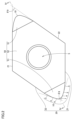
- FIG. 2 is a schematic plan view showing the configuration of the cutting tool according to the first embodiment.
- FIG. 3 is an enlarged schematic view of region III in FIG.
- FIG. 4 is a schematic cross-sectional view taken along line IV-IV in FIG.
- FIG. 5 is a schematic perspective view showing a configuration of a cutting insert according to a second embodiment.
- FIG. 6 is a schematic plan view showing the configuration of a cutting insert according to the second embodiment.
- FIG. 7 is a schematic cross-sectional view taken along line VII-VII in FIG.
- FIG. 8 is a schematic cross-sectional view taken along line VIII-VIII in FIG.
- FIG. 9 is a schematic cross-sectional view taken along line IX-IX in FIG.
- FIG. 10 is a schematic cross-sectional view taken along line XX in FIG.
- FIG. 11 is a schematic cross-sectional view taken along line XI-XI in FIG.
- FIG. 12 is a schematic diagram showing the first processing method according to the present embodiment.
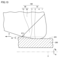
- FIG. 13 is an enlarged schematic view showing the processed state.
- FIG. 14 is a schematic diagram showing the relationship between the cutting depth and the side cutting edge angle of the cutting edge.
- FIG. 15 is a schematic side view showing the side rake angle of the cutting edge.
- FIG. 16 is a schematic diagram showing a second processing method according to the present embodiment.
- the cutting insert 100 has a surface involved in cutting that is composed of a cBN-based sintered body, a diamond-based sintered body, a ceramic, a cermet, or a cemented carbide, and includes a rake face 50, a clearance face 70, and a cutting edge 10 that is composed of a ridge line 20 between the rake face 50 and the clearance face 70.
- the cutting edge 10 has a first cutting edge portion 1 for corner machining, a second cutting edge portion 2 for low cutting edge machining, a third cutting edge portion 3 for high cutting edge machining, a fourth cutting edge portion 4 for finishing surface machining, a first connecting cutting edge portion 11 that connects the first cutting edge portion 1 and the fourth cutting edge portion 4, a second connecting cutting edge portion 12 that connects the second cutting edge portion 2 and the fourth cutting edge portion 4, and a third connecting cutting edge portion 13 that connects the second cutting edge portion 2 and the third cutting edge portion 3.
- the fourth cutting edge portion 4 is disposed between the first cutting edge portion 1 and the second cutting edge portion 2.
- the second cutting edge portion 2 is disposed between the fourth cutting edge portion 4 and the third cutting edge portion 3.
- Each of the first cutting edge portion 1, the second cutting edge portion 2, and the fourth cutting edge portion 4 has a curved shape.
- the radius of curvature of the first cutting edge portion 1 is 0.1 mm or more and 2.4 mm or less.
- the radius of curvature of the second cutting edge portion 2 is 3 mm or more.
- the radius of curvature of the fourth cutting edge portion 4 is 3 mm or more.
- the third cutting edge portion 3 has a straight shape.
- Each of the first connecting cutting edge portion 11, the second connecting cutting edge portion 12, and the third connecting cutting edge portion 13 has a curved shape.
- the radius of curvature of each of the first connecting cutting edge portion 11, the second connecting cutting edge portion 12, and the third connecting cutting edge portion 13 may be 0.2 mm or more.
- the clearance angle of each of the first cutting edge portion 1, the second cutting edge portion 2, the third cutting edge portion 3, and the fourth cutting edge portion 4 may be greater than or equal to 3° and less than or equal to 20°.
- the clearance surface 70 may have a constraint surface 71 that is constrained by the holder. If the apex angle of the second cutting edge portion 2 is a first angle ⁇ 8, and the apex angle of the ridge between the constraint surface 71 and the rake face 50 is a second angle ⁇ 9, the second angle ⁇ 9 may be smaller than the first angle ⁇ 8. The second angle ⁇ 9 may be 30° or more and 80° or less.
- the clearance surface 70 may have a constraint surface 71 that is constrained by the holder. If the apex angle of the second cutting edge portion 2 is a first angle ⁇ 8, and the apex angle of the ridge between the constraint surface 71 and the rake face 50 is a second angle ⁇ 9, the second angle ⁇ 9 may be smaller than the first angle ⁇ 8.
- the first angle ⁇ 8 may be 35° or more and 85° or less.
- the clearance angle of the restraint surface 71 may be 0°.
- a processing method is a processing method using a cutting insert described in any one of (1) to (6) above, in which the side rake angle of the second cutting edge portion 2 in a pulling process for cutting a workpiece using the second cutting edge portion 2 may be greater than or equal to -20° and less than or equal to 20°.
- the side rake angle of the third cutting edge portion 3 may be greater than or equal to -20° and less than or equal to 20°.
- the second cutting edge portion 2 may be within a range of 0.15 mm or less from a position closest to the workpiece in a direction perpendicular to the rotation axis.
- the lateral cutting edge angle of the second cutting edge portion 2 may be 70° or more and 89° or less.
- the third cutting edge portion 3 may be in a range of 0.05 mm to 0.5 mm from the position closest to the workpiece in a direction perpendicular to the rotation axis.
- the lateral cutting edge angle of the third cutting edge portion 3 may be 60° to 85°.
- the minimum value of the side cutting edge angle of the second cutting edge portion 2 may be the same as the side cutting edge angle of the third cutting edge portion 3.
- FIG. 1 is a schematic perspective view showing the configuration of the cutting insert according to the first embodiment.
- the cutting insert 100 according to the first embodiment has a blade member 6 and a base metal 7.
- the blade member 6 is attached to the base metal 7.
- the blade member 6 is involved in cutting.
- the planar shape of the base metal 7 is not particularly limited, but is, for example, a rhombus.
- the blade member 6 is joined to an acute corner portion of the base metal 7.
- the base metal 7 is made of, for example, cemented carbide or cermet.
- the cutting insert 100 according to this embodiment is formed by joining the blade member 6 to an acute corner portion of the base metal 7, but the entire cutting insert 100 may be formed of the blade member 6.
- a countersunk portion 8 is formed at the acute corner of the base metal 7 by partially recessing part of the upper surface.
- the blade member 6 is joined to the base metal 7 at the countersunk portion 8 by a joining means such as brazing.
- the blade member 6 is composed of a cBN-based sintered body, a diamond-based sintered body, ceramics, a cermet, or a cemented carbide.
- the cBN-based sintered body is a sintered body containing cBN (cubic boron nitride) at a volume ratio of 10% to 99.9%.
- the diamond-based sintered body is a sintered body containing diamond at a volume ratio of 10% to 99.9%.
- the ceramic is not particularly limited, but for example, ceramics such as alumina (Al 2 O 3 ), silicon nitride (Si 3 N 4 ), and titanium carbide (TiC) can be preferably used.
- the cermet is not particularly limited, but for example, nitride-based cermet and carbide-based cermet can be preferably used.
- the cutting insert 100 has a rake face 50, a clearance face 70, a cutting edge 10, and a bottom surface 60.
- the cutting edge 10 is formed by a ridge 20 between the rake face 50 and the clearance face 70.
- the ridge 20 has two cutting edges 10, two first ridge portions 21, and two second ridge portions 22.
- the cutting edge 10 is a part of the ridge 20.
- the clearance face 70 has a first clearance portion 30, a second clearance portion 40, and a restraining surface 71.
- the first clearance portion 30 is continuous with the cutting edge 10.
- the second clearance portion 40 is continuous with each of the first clearance portion 30 and the bottom surface 60.
- the cutting edge 10 has a first cutting edge portion 1 for corner processing, a second cutting edge portion 2 for low-depth cutting, a third cutting edge portion 3 for high-depth cutting, and a fourth cutting edge portion 4 for finishing surface processing.
- the fourth cutting edge portion 4 is disposed between the first cutting edge portion 1 and the second cutting edge portion 2.
- the second cutting edge portion 2 is disposed between the fourth cutting edge portion 4 and the third cutting edge portion 3.
- FIG. 2 is a schematic plan view showing the configuration of the cutting tool according to the first embodiment.
- the schematic plan view shown in FIG. 2 shows the state as seen along a straight line perpendicular to the rake face 50.
- the first cutting edge portion 1 has a curved shape.
- the first cutting edge portion 1 is curved so as to be convex outward.
- the first cutting edge portion 1 is a corner cutting edge portion.
- the radius of curvature of the first cutting edge portion 1 is 0.1 mm or more and 2.4 mm or less.
- the radius of curvature of the first cutting edge portion 1 is not particularly limited, but may be 0.2 mm or more and 2.2 mm or less, 0.4 mm or more and 2.0 mm or less, or 0.6 mm or more and 1.8 mm or less.
- the fourth cutting edge portion 4 has a curved shape.
- the radius of curvature of the fourth cutting edge portion 4 is 3 mm or more.
- the radius of curvature of the fourth cutting edge portion 4 is not particularly limited, but may be 5 mm or more, 10 mm or more, 20 mm or more, or 40 mm or more.
- the radius of curvature of the fourth cutting edge portion 4 may be 80 mm or less, 70 mm or less, or 60 mm or less.
- the second cutting edge portion 2 has a curved shape.
- the radius of curvature of the second cutting edge portion 2 is 3 mm or more.
- the radius of curvature of the second cutting edge portion 2 is not particularly limited, but may be 5 mm or more, 10 mm or more, 20 mm or more, or 40 mm or more.
- the radius of curvature of the second cutting edge portion 2 may be 80 mm or less, 70 mm or less, or 60 mm or less.
- the radius of curvature of the second cutting edge portion 2 may be different from or the same as the radius of curvature of the fourth cutting edge portion 4.
- the third cutting edge portion 3 has a straight line shape.
- the length of the third cutting edge portion 3 may be longer than the length of the second cutting edge portion 2.
- the length of the second cutting edge portion 2 is the length measured when the curved second cutting edge portion 2 is made straight.
- the length of the third cutting edge portion 3 is, for example, 0.5 mm or more and 5.0 mm or less.
- the scooping surface 50 has a first scooping surface portion 51 and a second scooping surface portion 52.
- the first scooping surface portion 51 is formed of a blade member 6.
- the second scooping surface portion 52 is formed of a base metal 7.
- a through hole 5 is formed in the second scooping surface portion 52.
- the cutting insert according to this embodiment has two cutting edges 10. When viewed along a straight line perpendicular to the cutting face 50, the through hole 5 is located between the two cutting edges 10.
- Each of the two cutting edges 10 may have one first cutting edge portion 1, two second cutting edge portions 2, two third cutting edge portions 3, and two fourth cutting edge portions 4.
- the first cutting edge portion 1 may be located between the two fourth cutting edge portions 4.
- each of the two cutting edges 10 When viewed along a straight line perpendicular to the cutting face 50, each of the two cutting edges 10 may have a shape that is line-symmetrical with respect to a straight line (a diagonal line of the cutting insert) that passes through the two first cutting edge portions 1. Each of the two cutting edges 10 may have a shape that is two-fold symmetrical with respect to an axis that passes through the through hole 5.
- the first ridges 21 and the second ridges 22 are formed by the base metal 7.
- the cutting edge 10 is formed by the blade member 6.
- the two first ridges 21 face each other.
- the two second ridges 22 face each other.
- each of the two first ridges 21 and each of the two second ridges 22 has a linear shape.
- the first third cutting edge portion 3 may be connected to the first ridge portion 21, and the second third cutting edge portion 3 may be connected to the second ridge portion 22.
- the length of the first ridge portion 21 may be longer than the length of the third cutting edge portion 3 connected to the first ridge portion 21.
- the length of the second ridge portion 22 may be longer than the length of the third cutting edge portion 3 connected to the second ridge portion 22.
- the apex angle of the second cutting edge portion 2 is a first angle ⁇ 8.
- the first angle ⁇ 8 is an angle formed by a straight line passing through both ends of each of the two second cutting edge portions 2.
- the clearance surface 70 has a constraint surface 71 that is constrained to the holder (see FIG. 1).
- the clearance angle of the constraint surface 71 is, for example, 0°.
- the clearance angle of the constraint surface 71 is the angle of the constraint surface 71 with respect to a plane perpendicular to the rake face 50.
- the apex angle of the ridge between the constraint surface 71 and the rake face 50 is a second angle ⁇ 9.
- the second angle ⁇ 9 is an angle formed by the first ridge portion 21 and the second ridge portion 22.
- the first angle ⁇ 8 is, for example, 70°.
- the first angle ⁇ 8 may be greater than or equal to 35° and less than or equal to 85°, greater than or equal to 45° and less than or equal to 80°, or greater than or equal to 55° and less than or equal to 75°.
- the second angle ⁇ 9 is smaller than the first angle ⁇ 8.
- the second angle ⁇ 9 is, for example, 55°.
- the second angle ⁇ 9 may be greater than or equal to 30° and less than or equal to 80°, greater than or equal to 35° and less than or equal to 70°, or greater than or equal to 40° and less than or equal to 60°.
- the third cutting edge portion 3 may be inclined relative to the first ridge portion 21.
- the third cutting edge portion 3 may be inclined relative to the second ridge portion 22.
- the apex angle of the third cutting edge portion 3 may be smaller than the first angle ⁇ 8.
- the apex angle of the third cutting edge portion 3 may be larger than the second angle ⁇ 9.
- the apex angle of the third cutting edge portion 3 is the angle formed by the two third cutting edge portions 3 when viewed along a straight line perpendicular to the rake face 50.
- FIG. 3 is an enlarged schematic diagram of region III in FIG. 1.
- the cutting edge 10 has a first connecting cutting edge portion 11, a second connecting cutting edge portion 12, and a third connecting cutting edge portion 13.
- the first connecting cutting edge portion 11 connects the first cutting edge portion 1 and the fourth cutting edge portion 4.
- the first connecting cutting edge portion 11 is located between the first cutting edge portion 1 and the fourth cutting edge portion 4.
- the second connecting cutting edge portion 12 connects the second cutting edge portion 2 and the fourth cutting edge portion 4.
- the second connecting cutting edge portion 12 is located between the second cutting edge portion 2 and the fourth cutting edge portion 4.
- the third connecting cutting edge portion 13 connects the second cutting edge portion 2 and the third cutting edge portion 3.
- the third connecting cutting edge portion 13 is located between the second cutting edge portion 2 and the third cutting edge portion 3.
- each of the first connecting cutting edge portion 11, the second connecting cutting edge portion 12, and the third connecting cutting edge portion 13 When viewed along a straight line perpendicular to the cutting face 50, each of the first connecting cutting edge portion 11, the second connecting cutting edge portion 12, and the third connecting cutting edge portion 13 has a curved shape. Each of the first connecting cutting edge portion 11, the second connecting cutting edge portion 12, and the third connecting cutting edge portion 13 is curved so as to be convex outward. The radius of curvature of the third connecting cutting edge portion 13 may be greater than the radius of curvature of each of the first connecting cutting edge portion 11 and the second connecting cutting edge portion 12.
- the radius of curvature of each of the first connecting cutting edge portion 11, the second connecting cutting edge portion 12, and the third connecting cutting edge portion 13 may be, for example, 0.2 mm or more.
- the radius of curvature of each of the first connecting cutting edge portion 11, the second connecting cutting edge portion 12, and the third connecting cutting edge portion 13 may be, for example, 0.3 mm or more, or 0.5 mm or more.
- the radius of curvature of each of the first connecting cutting edge portion 11, the second connecting cutting edge portion 12, and the third connecting cutting edge portion 13 may be less than 3 mm, or less than 2 mm.
- the first connecting cutting edge portion 11 may have a different radius of curvature from the adjacent first cutting edge portion 1 and fourth cutting edge portion 4.
- the second connecting cutting edge portion 12 may have a different radius of curvature from the adjacent second cutting edge portion 2 and fourth cutting edge portion 4.
- the third connecting cutting edge portion 13 may have a different radius of curvature from the adjacent second cutting edge portion 2 and third cutting edge portion 3.
- the first flank portion 30 has a first flank region 31, a second flank region 32, a third flank region 33, a fourth flank region 34, a fifth flank region 35, a sixth flank region 36, and a seventh flank region 37.
- the first flank region 31 is connected to the first cutting edge portion 1.
- the second flank region 32 is connected to the second cutting edge portion 2.
- the third flank region 33 is connected to the third cutting edge portion 3.
- the fourth flank region 34 is connected to the fourth cutting edge portion 4.
- the fifth flank region 35 is connected to the first connecting cutting edge portion 11.
- the sixth flank region 36 is connected to the second connecting cutting edge portion 12.
- the seventh flank region 37 is connected to the third connecting cutting edge portion 13.
- the first flank region 31, the second flank region 32, the third flank region 33, the fourth flank region 34, the fifth flank region 35, the sixth flank region 36, and the seventh flank region 37 are formed by the blade member 6.
- the second flank portion 40 has a first side region 41, a second side region 42, a third side region 43, a fourth side region 44, a fifth side region 45, a sixth side region 46, and a seventh side region 47.
- the first side region 41 is connected to each of the first flank region 31 and the bottom surface 60.
- the second side region 42 is connected to each of the second flank region 32 and the bottom surface 60.
- the third side region 43 is connected to each of the third flank region 33 and the bottom surface 60.
- the fourth side region 44 is connected to each of the fourth flank region 34 and the bottom surface 60.
- the fifth side region 45 is connected to the fifth flank region 35 and the bottom surface 60.
- the sixth side region 46 is connected to the sixth flank region 36 and the bottom surface 60.
- the seventh side region 47 is connected to the seventh flank region 37 and the bottom surface 60.
- the first side region 41, the second side region 42, the third side region 43, the fourth side region 44, the fifth side region 45, the sixth side region 46, and the seventh side region 47 are formed by the base metal 7.
- FIG. 4 is a schematic cross-sectional view taken along line IV-IV in FIG. 2.
- the cross section shown in FIG. 4 passes through the midpoints of the two first cutting edge portions 1.
- a straight line passing through the midpoints of the two first cutting edge portions 1 is a diagonal line of the cutting insert 100.
- the through hole 5 passes through the base metal 7.
- the through hole 5 opens into each of the rake face 50 and the bottom face 60.
- the rake face 70 may be inclined perpendicularly to the rake face 50.
- each of the first rake face portion 30 and the second rake face portion 40 may be inclined perpendicularly to the rake face 50.
- the cutting insert 100 according to the second embodiment differs from the cutting insert 100 according to the first embodiment mainly in the configuration in which the clearance angle of the first clearance portion 30 is 3° or more and 20° or less, and other configurations are substantially the same as those of the cutting insert 100 according to the first embodiment.
- the configurations different from the cutting insert 100 according to the first embodiment will be mainly described.
- FIG. 5 is a schematic perspective view showing the configuration of the cutting insert according to the second embodiment.
- the flank 70 has a holder restraining surface 71, a first flank portion 30, and a second flank portion 40.
- the second flank portion 40 is continuous with the holder restraining surface 71.
- the first flank portion 30 is inclined inward with respect to a plane perpendicular to the rake face 50.
- the second flank portion 40 is inclined with respect to the holder restraining surface 71.
- the second flank portion 40 is formed of a base metal.
- the second flank portion 40 is continuous with each of the first flank portion 30 and the bottom surface 60.
- FIG. 6 is a schematic plan view showing the configuration of a cutting insert according to the second embodiment.
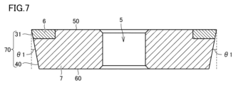
- FIG. 7 is a schematic cross-sectional view taken along line VII-VII in FIG. 6. The cross section shown in FIG. 7 passes through the midpoints of each of the two first cutting edge portions 1.
- the clearance angle of the first cutting edge portion 1 is the inclination angle of the first clearance surface region 31 with respect to a plane perpendicular to the rake face 50.
- the first clearance angle ⁇ 1 may be, for example, 3° or more and 20° or less, 5° or more and 18° or less, or 7° or more and 15° or less.
- FIG. 8 is a schematic cross-sectional view taken along line VIII-VIII in FIG. 6.
- the cross section shown in FIG. 8 intersects with each of the two fourth cutting edge portions 4 and is perpendicular to the diagonal of the cutting insert.
- the fourth clearance region 34 is inclined inward with respect to a plane perpendicular to the rake face 50.
- the clearance angle of the fourth cutting edge portion 4 (fourth clearance angle ⁇ 4) is the inclination angle of the fourth clearance region 34 with respect to the plane perpendicular to the rake face 50.
- the fourth clearance angle ⁇ 4 may be, for example, 3° or more and 20° or less, 5° or more and 18° or less, or 7° or more and 15° or less.
- FIG. 9 is a schematic cross-sectional view taken along line IX-IX in FIG. 6.
- the cross section shown in FIG. 9 intersects with each of the two second cutting edge portions 2 and is perpendicular to the diagonal of the cutting insert.
- the second clearance region 32 is inclined inward with respect to a plane perpendicular to the rake face 50.
- the clearance angle of the second cutting edge portion 2 (second clearance angle ⁇ 2) is the inclination angle of the second clearance region 32 with respect to the plane perpendicular to the rake face 50.
- the second clearance angle ⁇ 2 may be, for example, 3° or more and 20° or less, 5° or more and 18° or less, or 7° or more and 15° or less.
- FIG. 10 is a schematic cross-sectional view taken along line X-X in FIG. 6.
- the cross section shown in FIG. 10 intersects with each of the two third cutting edge portions 3 and is perpendicular to the diagonal of the cutting insert.
- the third clearance region 33 is inclined inward with respect to a plane perpendicular to the rake face 50.
- the clearance angle of the third cutting edge portion 3 (third clearance angle ⁇ 3) is the inclination angle of the third clearance region 33 with respect to the plane perpendicular to the rake face 50.
- the third clearance angle ⁇ 3 may be, for example, 3° or more and 20° or less, 5° or more and 18° or less, or 7° or more and 15° or less.
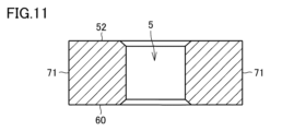
- FIG. 11 is a schematic cross-sectional view taken along line XI-XI in FIG. 6.
- the cross-section shown in FIG. 11 intersects with each of the first ridge portion 21 and the second ridge portion 22, and is perpendicular to the diagonal of the cutting insert.
- the holder clamping surface 71 is perpendicular to the rake face 50.
- the clearance angle of the holder clamping surface 71 is the inclination angle of the holder clamping surface 71 with respect to a plane perpendicular to the rake face 50.
- the clearance angle of the holder clamping surface 71 is, for example, 0°.
- a processing method according to this embodiment will be described.
- a workpiece is processed using the cutting insert 100 according to this embodiment.
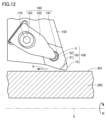
- FIG. 12 is a schematic diagram showing a first processing method according to this embodiment.
- the cutting insert 100 is attached to the holder 150 using a pressing member 160.
- the pressing member 160 has a main body portion 162 and an insertion portion 161.
- the insertion portion 161 is inserted into the through hole 5 of the cutting insert 100.
- the main body portion 162 has an attachment hole 163.
- a fastening screw 170 is inserted into the attachment hole 163. In this way, the pressing member 160 is fixed to the holder 150.
- the pressing member 160 pulls the cutting insert 100 toward the holder 150, thereby fixing the cutting insert 100 to the holder 150.
- the cutting insert 100 is capable of external diameter drawing.
- the workpiece 200 has an outer peripheral surface 201.
- the drawing process is performed while moving the cutting insert 100 in a first feed direction A.
- the first feed direction A is the direction from the cutting insert 100 toward the holder 150.
- the workpiece 200 is machined using the cutting edge 10.
- the first feed direction A is parallel to the rotation axis X of the workpiece 200.
- the workpiece 200 rotates in a rotation direction R around the rotation axis X.
- FIG. 13 is an enlarged schematic diagram showing the machining state.
- the enlarged schematic diagram shown in FIG. 13 shows the state as seen along a straight line perpendicular to the rake face 50.
- the cutting edge 10 cuts into the workpiece 200 with a cutting depth ap.
- the lateral cutting edge angle of the second cutting edge portion 2 during drawing is the fifth angle ⁇ 5.
- the fifth angle ⁇ 5 is the angle between the tangent to the cutting edge 10 at the contact point between the outer peripheral surface 201 of the workpiece 200 and the cutting edge 10, and a straight line perpendicular to the rotation axis X of the workpiece 200.
- Figure 14 is a schematic diagram showing the relationship between the depth of cut and the side cutting edge angle of the cutting edge. As shown in Figure 14, as the depth of cut into the workpiece 200 changes, the side cutting edge angle of the second cutting edge portion 2 changes. Specifically, as the depth of cut into the workpiece 200 increases, the side cutting edge angle of the second cutting edge portion 2 monotonically decreases.
- the side cutting edge angle of the second cutting edge portion 2 is less than 90°. In a drawing process in which the workpiece 200 is machined using the second cutting edge portion 2, the side cutting edge angle of the second cutting edge portion 2 may be 70° or more and 89° or less, or 73° or more and 86° or less.
- the second cutting edge portion 2 is used in low-depth cutting. Specifically, the depth of cut of the second cutting edge portion 2 is, for example, 0.15 mm or less. The depth of cut of the second cutting edge portion 2 may be, for example, 0.1 mm or less, or 0.05 mm or less. From another perspective, the second cutting edge portion 2 may be in a range of 0.15 mm or less from the position closest to the workpiece 200 in the direction perpendicular to the rotation axis.
- the side cutting edge angle of the third cutting edge portion 3 does not change. Specifically, when the amount of cutting into the workpiece 200 increases, the side cutting edge angle of the third cutting edge portion 3 remains constant. For example, when the amount of cutting is in the range of 0.05 mm or more and 0.5 mm or less, the side cutting edge angle of the third cutting edge portion 3 may be constant.
- the side cutting edge angle of the third cutting edge portion 3 is, for example, 60° or more and 85° or less.
- the side cutting edge angle of the third cutting edge portion 3 may be, for example, 63° or more and 82° or less, or 65° or more and 80° or less.
- the minimum value of the side cutting edge angle of the second cutting edge portion 2 is the same as the side cutting edge angle of the third cutting edge portion 3.
- the third cutting edge portion 3 is used in high-depth drawing. Specifically, the depth of cut of the third cutting edge portion 3 is, for example, 0.05 mm or more. The depth of cut of the third cutting edge portion 3 may be, for example, 0.1 mm or more, or may be greater than 0.15 mm. The depth of cut of the third cutting edge portion 3 may be 0.5 mm or less. From another perspective, the third cutting edge portion 3 may be in the range of 0.05 mm or more and 0.5 mm or less from the position closest to the workpiece 200 in the direction perpendicular to the rotation axis.
- FIG. 15 is a schematic side view showing the side rake angle of the cutting edge.
- the schematic side view shown in FIG. 15 shows the state as seen along a straight line perpendicular to the rotation axis X of the workpiece 200.
- the cutting insert 100 is fed in a first feed direction A along a direction parallel to the rotation axis X of the workpiece 200.
- the side rake angle of the second cutting edge portion 2 is the inclination angle of the second cutting edge portion 2 with respect to a straight line C1 parallel to the rotation axis X of the workpiece 200.
- the side rake angle of the second cutting edge portion 2 is a sixth angle ⁇ 6.
- the sixth angle ⁇ 6 may be, for example, -20° or more and 20° or less.
- the sixth angle ⁇ 6 may be -15° or more and 15° or less, or -10° or more and 10° or less.
- the cutting insert 100 is fed in the first feed direction A along a direction parallel to the rotation axis X of the workpiece 200.
- the side rake angle of the third cutting edge portion 3 is the inclination angle of the third cutting edge portion 3 with respect to a straight line C2 parallel to the rotation axis X of the workpiece 200.
- the side rake angle of the third cutting edge portion 3 is a seventh angle ⁇ 7.
- the seventh angle ⁇ 7 may be, for example, -20° or more and 20° or less.
- the seventh angle ⁇ 7 may be -15° or more and 15° or less, or -10° or more and 10° or less.
- the side rake angle is a positive angle. Conversely, during cutting, if the cutting edge 10 lags behind the rake face 50, the side rake angle is a negative angle.
- FIG. 16 is a schematic diagram showing the second machining method according to this embodiment.
- end face machining and outer diameter machining may be performed.
- the workpiece 200 has an outer peripheral surface 201 and an end surface 202.
- the outer peripheral surface 201 is parallel to the rotation axis X of the workpiece 200.
- the end surface 202 is perpendicular to the rotation axis X of the workpiece 200.
- the pushing and corner machining are performed while moving the cutting insert 100 in the second feed direction B1. In the pushing and corner machining, the workpiece 200 is machined using the first cutting edge portion 1.
- the pulling is performed while moving the cutting insert 100 in the third feed direction B2.
- the workpiece 200 is machined using the second cutting edge portion 2.
- the workpiece 200 is machined using the third cutting edge portion 3.
- the second feed direction B1 is perpendicular to the rotation axis X of the workpiece 200.
- the third feed direction B2 is parallel to the rotation axis X of the workpiece 200.
- the cutting insert 100 has a second cutting edge portion 2 for low-depth cutting and a third cutting edge portion 3 for high-depth cutting.
- the radius of curvature of the second cutting edge portion 2 is 3 mm or more.
- the third cutting edge portion 3 has a straight line shape.
- the side cutting edge angle of the second cutting edge portion 2 decreases as the depth of cut increases. By reducing the side cutting edge angle as the load increases, chipping of the cutting edge 10 can be prevented. On the other hand, if the side cutting edge angle becomes too small, the stability of the cutting process decreases.
- the third cutting edge portion 3 for high-depth cutting has a linear shape. Therefore, in high-depth cutting, the lateral cutting edge angle can be maintained constant regardless of the amount of cut. Therefore, in high-depth cutting, the stability of the cutting process can be prevented from decreasing. Therefore, the cutting insert 100 can have a long life in both low-depth cutting and high-depth cutting.
- the cutting insert 100 according to this embodiment has the fourth cutting edge portion 4 for finishing the surface, the roughness of the finished surface can be significantly improved. Therefore, a stable and good surface roughness can be obtained even in high-efficiency machining.
- high-efficiency machining refers to machining in which the volume of the workpiece 200 that can be removed per unit time is, for example, 10 cm3 /min or more.
- the clearance angle of each of the first cutting edge portion 1, the second cutting edge portion 2, the third cutting edge portion 3, and the fourth cutting edge portion 4 may be greater than or equal to 3° and less than or equal to 20°.
- the clearance surface 70 may have a restraining surface 71 that is restrained by the holder. If the apex angle of the second cutting edge portion 2 is a first angle ⁇ 8 and the apex angle of the ridge between the restraining surface 71 and the rake face 50 is a second angle ⁇ 9, the second angle ⁇ 9 may be smaller than the first angle ⁇ 8. This makes it possible to increase the side cutting edge angle of the second cutting edge portion 2 while maintaining a high restraining force of the cutting insert by the holder.
- the clearance angle of the restraining surface 71 may be 0°. This allows the restraining force of the cutting insert by the holder to be maintained at an even higher level.
- the side rake angle of the second cutting edge portion 2 may be greater than or equal to -20° and less than or equal to 20°. This reduces the load on the second cutting edge portion 2. As a result, damage to the second cutting edge portion 2 can be suppressed. This further extends the life of the cutting insert 100.
- the side rake angle of the third cutting edge portion 3 may be -20° or more and 20° or less. This reduces the load on the third cutting edge portion 3. As a result, damage to the third cutting edge portion 3 can be suppressed. Therefore, the life of the cutting insert 100 can be further extended.
- the second cutting edge portion 2 may be within a range of 0.15 mm or less from the position closest to the workpiece 200 in the direction perpendicular to the rotation axis.
- the lateral cutting edge angle of the second cutting edge portion 2 may be 70° or more and 89° or less. This reduces the load on the second cutting edge portion 2. As a result, damage to the second cutting edge portion 2 can be suppressed. Therefore, the life of the cutting insert 100 can be further extended in a low-depth pull process.
- the third cutting edge portion 3 may be in the range of 0.05 mm to 0.5 mm from the position closest to the workpiece 200 in the direction perpendicular to the rotation axis.
- the lateral cutting edge angle of the third cutting edge portion 3 may be 60° to 85°. This reduces the load on the third cutting edge portion 3. As a result, damage to the third cutting edge portion 3 can be suppressed. Therefore, the life of the cutting insert 100 can be further extended in high-depth pull machining.
- Example 1 Low cutting depth machining conditions> Cutting inserts 100 (samples SA1 to SA35 and SB1 to SB9) having shapes shown in Tables 1 and 2 were produced as prototypes, and cutting evaluation was performed under the following conditions.
- the cutting inserts 100 of samples SA1 to SA35 and SB1 to SB9 have a blade member 6 and a base metal 7 (see FIG. 1).
- the material of the blade member 6 was a cBN-based sintered body.
- the first cutting edge, second cutting edge, third cutting edge, fourth cutting edge, first connecting portion, second connecting portion, and third connecting portion correspond to the first cutting edge portion 1, the second cutting edge portion 2, the third cutting edge portion 3, the fourth cutting edge portion 4, the first connecting cutting edge portion 11, the second connecting cutting edge portion 12, and the third connecting cutting edge portion 13, respectively.
- the numerical values listed in each column for the first cutting edge, second cutting edge, fourth cutting edge, first connecting portion, second connecting portion, and third connecting portion indicate the radius of curvature of the corresponding portion.
- Cutting inserts 100 of samples SA1 to SA35 are examples.
- the radius of curvature of the first cutting edge portion 1 was 0.1 mm or more and 2.4 mm or less.
- the fourth cutting edge portion 4 was curved with a radius of curvature of 3 mm or more.
- the second cutting edge portion 2 was curved with a radius of curvature of 3 mm or more.
- the third cutting edge portion 3 was linear.
- Each of the first connecting cutting edge portion 11, the second connecting cutting edge portion 12, and the third connecting cutting edge portion 13 was curved.
- Cutting inserts 100 of samples SB1 to SB9 are comparative examples.
- the radius of curvature of the first cutting edge portion 1 was 0.09 mm.
- the radius of curvature of the first cutting edge portion 1 was 2.5 mm.
- the radius of curvature of the second cutting edge portion 2 was 2.9 mm.
- the third cutting edge portion 3 was curved with a radius of curvature of 30 mm.
- the first connecting cutting edge portion 11 was linear.
- the second connecting cutting edge portion 12 was linear.
- the third connecting cutting edge portion 13 was linear.
- the second cutting edge portion 2 was linear, and the third connecting cutting edge portion 13 and the third cutting edge portion 3 were not formed.
- the third connecting cutting edge portion 13 and the third cutting edge portion 3 were not formed.
- the cutting insert 100 was attached to the holder 150, and the following workpiece 200 was machined under the following cutting conditions.
- the cutting time (tool life) when the cutting edge 10 of the cutting insert 100 was chipped was evaluated.
- the side rake angle of the cutting edge 10 was set to be -21° or more and 21° or less.
- the side cutting edge angle of the second cutting edge portion 2 was set to be 69° or more and 89° or less. Only in the cutting insert 100 of sample SA35, the side cutting edge angle of the third cutting edge portion 3 was set to be 80°.
- the cutting inserts 100 of samples SA1 to SA3 it was confirmed that the cutting inserts 100 have a long tool life when the radius of curvature of the first cutting edge portion 1 is 0.1 mm or more and 2.4 mm or less.
- the cutting inserts 100 of samples SA4 to SA6 it was confirmed that the cutting inserts 100 have a long tool life when the radius of curvature of the second cutting edge portion 2 is 3 mm or more and 20 mm or less.
- the cutting inserts 100 of samples SA7 to SA9 it was confirmed that the cutting inserts 100 have a long tool life when the radius of curvature of the fourth cutting edge portion 4 is 3 mm or more and 20 mm or less.
- the cutting inserts 100 of samples SA15 to SA18 it was confirmed that the cutting inserts 100 have a long tool life when the clearance angles of the first cutting edge portion 1, the second cutting edge portion 2, the third cutting edge portion 3, and the fourth cutting edge portion 4 are each 20° or less.
- the cutting inserts 100 of samples SA19 to SA22 it was confirmed that the cutting inserts 100 have a long tool life when the apex angle of the holder clamping surface 71 is 30° or more and 80° or less.
- the cutting inserts 100 of samples SA23 to SA25 it was confirmed that the cutting inserts 100 have a long tool life when the clearance angle of the holder clamping surface 71 is 11° or less.
- the cutting inserts 100 of samples SA26 to SA29 it was confirmed that the cutting inserts 100 have a long tool life when the side rake angle of the cutting edge 10 is greater than -20° and less than 20°.
- Cutting inserts 100 (samples SC1 to SC36 and SD1 to SD9) having shapes shown in Tables 5 and 6 were produced and evaluated under the following conditions.
- the cutting inserts 100 of samples SC1 to SC36 and SD1 to SD9 have a blade member 6 and a base metal 7 (see FIG. 1).
- the material of the blade member 6 was a cBN-based sintered body.
- the first cutting edge, second cutting edge, third cutting edge, fourth cutting edge, first connecting portion, second connecting portion, and third connecting portion correspond to the first cutting edge portion 1, the second cutting edge portion 2, the third cutting edge portion 3, the fourth cutting edge portion 4, the first connecting cutting edge portion 11, the second connecting cutting edge portion 12, and the third connecting cutting edge portion 13, respectively.
- the numerical values listed in each column for the first cutting edge, second cutting edge, fourth cutting edge, first connecting portion, second connecting portion, and third connecting portion indicate the radius of curvature of the corresponding portion.
- Cutting inserts 100 of samples SC1 to SC36 are examples.
- the radius of curvature of the first cutting edge portion 1 was 0.1 mm or more and 2.4 mm or less.
- the fourth cutting edge portion 4 was curved with a radius of curvature of 3 mm or more.
- the second cutting edge portion 2 was curved with a radius of curvature of 3 mm or more.
- the third cutting edge portion 3 was linear.
- Each of the first connecting cutting edge portion 11, the second connecting cutting edge portion 12, and the third connecting cutting edge portion 13 was curved.
- Cutting inserts 100 of samples SD1 to SD9 are comparative examples.
- the radius of curvature of the first cutting edge portion 1 was 0.09 mm.
- the radius of curvature of the first cutting edge portion 1 was 2.5 mm.
- the radius of curvature of the second cutting edge portion 2 was 2.9 mm.
- the third cutting edge portion 3 was curved with a radius of curvature of 30 mm.
- the first connecting cutting edge portion 11 was linear.
- the second connecting cutting edge portion 12 was linear.
- the third connecting cutting edge portion 13 was linear.
- the second cutting edge portion 2 was linear, and the third connecting cutting edge portion 13 and the third cutting edge portion 3 were not formed.
- the third connecting cutting edge portion 13 and the third cutting edge portion 3 were not formed.
- the cutting insert 100 was attached to the holder 150, and the following workpiece 200 was machined under the following cutting conditions.
- the cutting time (tool life) when the cutting edge 10 of the cutting insert 100 was chipped was evaluated.
- the side rake angle of the cutting edge 10 was set to be -21° or more and 21° or less.
- the side cutting edge angle of the third cutting edge portion 3 was set to be 59° or more and 86° or less. Only in the cutting inserts 100 of samples SD8 and SD9, the side cutting edge angle of the second cutting edge portion 2 was set to be 85°.
- the cutting inserts 100 of samples SC1 to SC3 it was confirmed that the cutting inserts 100 have a long tool life when the radius of curvature of the first cutting edge portion 1 is 0.1 mm or more and 2.4 mm or less.
- the cutting inserts 100 of samples SC4 to SC6 it was confirmed that the cutting inserts 100 have a long tool life when the radius of curvature of the second cutting edge portion 2 is 3 mm or more and 20 mm or less.
- the cutting inserts 100 of samples SC7 to SC9 it was confirmed that the cutting inserts 100 have a long tool life when the radius of curvature of the fourth cutting edge portion 4 is 3 mm or more and 20 mm or less.
- the cutting inserts 100 of samples SC15 to SC18 it was confirmed that the cutting inserts 100 have a long tool life when the clearance angles of the first cutting edge portion 1, the second cutting edge portion 2, the third cutting edge portion 3, and the fourth cutting edge portion 4 are each 20° or less.
- the cutting inserts 100 of samples SC19 to SC22 it was confirmed that the cutting inserts 100 have a long tool life when the apex angle of the holder clamping surface 71 is 30° or more and 80° or less.
- the cutting inserts 100 of samples SC23 to SC25 it was confirmed that the cutting inserts 100 have a long tool life when the clearance angle of the holder clamping surface 71 is 11° or less.
- the cutting inserts 100 of samples SC26 to SC29 it was confirmed that the cutting inserts 100 have a long tool life when the side rake angle of the cutting edge 10 is greater than -20° and less than 20°.
- the cutting inserts 100 of samples SC32 to SC35 it was confirmed that the cutting inserts 100 have a long tool life when the side cutting edge angle of the third cutting edge portion 3 is 60° or more and 86° or less.
- the cutting inserts 100 of samples SB8 and SD8 had a long tool life under high depth of cut machining conditions, but did not have a long tool life under low depth of cut machining conditions.
- the cutting inserts 100 of samples SB9 and SD9 had a long tool life under low depth of cut machining conditions, but did not have a long tool life under high depth of cut machining conditions.
Landscapes
- Engineering & Computer Science (AREA)
- Mechanical Engineering (AREA)
- Cutting Tools, Boring Holders, And Turrets (AREA)
- Milling Processes (AREA)
Priority Applications (5)
| Application Number | Priority Date | Filing Date | Title |
|---|---|---|---|
| JP2024506910A JP7563667B1 (ja) | 2023-05-31 | 2023-05-31 | 切削インサートおよび加工方法 |
| CN202380098424.3A CN121194844A (zh) | 2023-05-31 | 2023-05-31 | 切削刀片以及加工方法 |
| US19/114,970 US12485492B2 (en) | 2023-05-31 | 2023-05-31 | Cutting insert and processing method |
| PCT/JP2023/020257 WO2024247156A1 (ja) | 2023-05-31 | 2023-05-31 | 切削インサートおよび加工方法 |
| EP23939632.8A EP4721898A1 (en) | 2023-05-31 | 2023-05-31 | Cutting insert and machining method |
Applications Claiming Priority (1)
| Application Number | Priority Date | Filing Date | Title |
|---|---|---|---|
| PCT/JP2023/020257 WO2024247156A1 (ja) | 2023-05-31 | 2023-05-31 | 切削インサートおよび加工方法 |
Publications (1)
| Publication Number | Publication Date |
|---|---|
| WO2024247156A1 true WO2024247156A1 (ja) | 2024-12-05 |
Family
ID=92969823
Family Applications (1)
| Application Number | Title | Priority Date | Filing Date |
|---|---|---|---|
| PCT/JP2023/020257 Ceased WO2024247156A1 (ja) | 2023-05-31 | 2023-05-31 | 切削インサートおよび加工方法 |
Country Status (5)
| Country | Link |
|---|---|
| US (1) | US12485492B2 (https=) |
| EP (1) | EP4721898A1 (https=) |
| JP (1) | JP7563667B1 (https=) |
| CN (1) | CN121194844A (https=) |
| WO (1) | WO2024247156A1 (https=) |
Families Citing this family (2)
| Publication number | Priority date | Publication date | Assignee | Title |
|---|---|---|---|---|
| JP1771198S (ja) * | 2023-09-08 | 2024-05-23 | 切削工具用インサート | |
| JP1771199S (ja) * | 2023-09-08 | 2024-05-23 | 切削工具用インサート |
Citations (5)
| Publication number | Priority date | Publication date | Assignee | Title |
|---|---|---|---|---|
| JP2004237438A (ja) * | 2003-01-16 | 2004-08-26 | Ngk Spark Plug Co Ltd | スローアウェイチップ及びバイト |
| WO2016190351A1 (ja) * | 2015-05-26 | 2016-12-01 | 京セラ株式会社 | 切削インサート、切削工具及びこれを用いた切削加工物の製造方法 |
| WO2017090770A1 (ja) * | 2015-11-28 | 2017-06-01 | 京セラ株式会社 | 切削インサート、切削工具及び切削加工物の製造方法 |
| JP2018534159A (ja) * | 2015-10-09 | 2018-11-22 | サンドビック インテレクチュアル プロパティー アクティエボラーグ | 旋削インサートおよび方法 |
| WO2019087496A1 (ja) | 2017-10-31 | 2019-05-09 | 住友電工ハードメタル株式会社 | 切削インサート |
Family Cites Families (21)
| Publication number | Priority date | Publication date | Assignee | Title |
|---|---|---|---|---|
| SE448431B (sv) * | 1985-07-03 | 1987-02-23 | Santrade Ltd | Vendsker for spanavskiljande bearbetning |
| DE59508102D1 (de) * | 1994-09-13 | 2000-05-04 | Widia Gmbh | Schneideinsatz |
| SE519133C2 (sv) * | 1998-10-13 | 2003-01-21 | Sandvik Ab | Borrskär för metallborrning |
| DE60041320D1 (de) * | 1999-11-25 | 2009-02-26 | Sumitomo Electric Industries | Schneidwerkzeug aus polykristallinem Hartmetall |
| US6862966B2 (en) * | 2001-06-13 | 2005-03-08 | Toledo Metal Spinning Company | Device to cut and deburr metal and method of use thereof |
| SE525829C2 (sv) * | 2002-06-26 | 2005-05-10 | Seco Tools Ab | Dubbelsidigt vändskär med bomberad biskäregg samt tillverkningsmetod för skäret |
| US7220083B2 (en) * | 2003-10-15 | 2007-05-22 | Tdy Industries, Inc. | Cutting insert for high feed face milling |
| SE530153C2 (sv) * | 2005-02-22 | 2008-03-11 | Seco Tools Ab | Skär för svarvning med ett perifert land av konstant bredd |
| EP1886749B1 (en) * | 2005-10-06 | 2017-08-09 | Sumitomo Electric Hardmetal Corp. | Cutting tool for high quality and high efficiency machining and cutting method using the cutting tool |
| SE531508C2 (sv) * | 2007-08-31 | 2009-05-05 | Sandvik Intellectual Property | Skär för spånavskiljande bearbetning med ett avstrykningssegment |
| EP2412462B1 (en) * | 2009-03-27 | 2015-05-13 | Kyocera Corporation | Cutting insert, cutting tool, and method of cutting material to be cut using the cutting tool |
| GB0907737D0 (en) * | 2009-05-06 | 2009-06-10 | Element Six Ltd | An insert for a cutting tool |
| WO2010147157A1 (ja) * | 2009-06-16 | 2010-12-23 | 株式会社タンガロイ | 切削用インサートおよび正面フライス |
| JP5762020B2 (ja) * | 2011-01-31 | 2015-08-12 | 京セラ株式会社 | 切削インサートおよび切削工具ならびにそれを用いた被削材の切削方法 |
| DE112016005138B4 (de) * | 2015-11-09 | 2024-02-29 | Kyocera Corporation | Schneidwerkzeug und Verfahren des Herstellens eines maschinell-bearbeiteten Produkts |
| JP7119780B2 (ja) * | 2018-08-30 | 2022-08-17 | 三菱マテリアル株式会社 | 切削インサートおよび刃先交換式切削工具 |
| WO2020045438A1 (ja) * | 2018-08-30 | 2020-03-05 | 三菱マテリアル株式会社 | 切削インサートおよび刃先交換式切削工具 |
| US20220097151A1 (en) * | 2020-09-28 | 2022-03-31 | Kennametal Inc. | Cutting insert for high feed face milling |
| WO2022180697A1 (ja) * | 2021-02-24 | 2022-09-01 | アイシン・エイ・ダブリュ工業株式会社 | 切削工具 |
| JP7193052B1 (ja) * | 2021-10-21 | 2022-12-20 | 住友電工ハードメタル株式会社 | 切削インサート |
| US11826834B1 (en) * | 2022-07-21 | 2023-11-28 | Sumitomo Electric Hardmetal Corp. | Cutting tool |
-
2023
- 2023-05-31 CN CN202380098424.3A patent/CN121194844A/zh active Pending
- 2023-05-31 JP JP2024506910A patent/JP7563667B1/ja active Active
- 2023-05-31 EP EP23939632.8A patent/EP4721898A1/en active Pending
- 2023-05-31 WO PCT/JP2023/020257 patent/WO2024247156A1/ja not_active Ceased
- 2023-05-31 US US19/114,970 patent/US12485492B2/en active Active
Patent Citations (5)
| Publication number | Priority date | Publication date | Assignee | Title |
|---|---|---|---|---|
| JP2004237438A (ja) * | 2003-01-16 | 2004-08-26 | Ngk Spark Plug Co Ltd | スローアウェイチップ及びバイト |
| WO2016190351A1 (ja) * | 2015-05-26 | 2016-12-01 | 京セラ株式会社 | 切削インサート、切削工具及びこれを用いた切削加工物の製造方法 |
| JP2018534159A (ja) * | 2015-10-09 | 2018-11-22 | サンドビック インテレクチュアル プロパティー アクティエボラーグ | 旋削インサートおよび方法 |
| WO2017090770A1 (ja) * | 2015-11-28 | 2017-06-01 | 京セラ株式会社 | 切削インサート、切削工具及び切削加工物の製造方法 |
| WO2019087496A1 (ja) | 2017-10-31 | 2019-05-09 | 住友電工ハードメタル株式会社 | 切削インサート |
Also Published As
| Publication number | Publication date |
|---|---|
| CN121194844A (zh) | 2025-12-23 |
| US20250256336A1 (en) | 2025-08-14 |
| JPWO2024247156A1 (https=) | 2024-12-05 |
| US12485492B2 (en) | 2025-12-02 |
| JP7563667B1 (ja) | 2024-10-08 |
| EP4721898A1 (en) | 2026-04-08 |
Similar Documents
| Publication | Publication Date | Title |
|---|---|---|
| JP7563667B1 (ja) | 切削インサートおよび加工方法 | |
| US7901161B2 (en) | Cutting insert and tool for chip removing machining | |
| CN102596459B (zh) | 切削镶刀及切削工具、以及使用该切削工具的切削加工物的制造方法 | |
| JP5379870B2 (ja) | 切削インサートおよび切削工具、ならびにそれらを用いた被削材の切削方法 | |
| JP5639656B2 (ja) | 切削インサートおよび切削工具、並びにそれらを用いた切削加工物の製造方法 | |
| EP0958873A1 (en) | Cutting insert for grooving | |
| CN111148590B (zh) | 切削刀片、切削刀具以及切削加工物的制造方法 | |
| JP6420239B2 (ja) | 切削インサート、切削工具および切削加工物の製造方法 | |
| CN115666827B (zh) | 切削刀片、切削刀具及切削加工物的制造方法 | |
| CN113613816A (zh) | 切削刀片、车削刀具以及切削加工物的制造方法 | |
| JP7612948B2 (ja) | 切削インサートおよび加工方法 | |
| JP4941082B2 (ja) | スローアウェイ式切削工具およびこれに装着される切刃チップ | |
| JP2002166305A (ja) | 切削工具 | |
| JP7325510B2 (ja) | 切削インサート、切削工具及び切削加工物の製造方法 | |
| JP2000071110A (ja) | スローアウェイチップ | |
| JP5887859B2 (ja) | 切削インサート | |
| JPH11197909A (ja) | スローアウェイチップ | |
| JP7673350B1 (ja) | 転削用切削工具および旋削用切削工具 | |
| JPH11320217A (ja) | 内径加工用スローアウェイチップ | |
| JP7023297B2 (ja) | 切削インサート、切削工具及び切削加工物の製造方法 | |
| JP4020507B2 (ja) | ツイストドリル | |
| JP4320562B2 (ja) | スローアウェイチップ | |
| WO2026094250A1 (ja) | 切削インサートおよび切削工具 | |
| JP2005052911A (ja) | スローアウェイチップ | |
| JP2007061990A (ja) | スローアウェイ式工具 |
Legal Events
| Date | Code | Title | Description |
|---|---|---|---|
| WWE | Wipo information: entry into national phase |
Ref document number: 2024506910 Country of ref document: JP |
|
| 121 | Ep: the epo has been informed by wipo that ep was designated in this application |
Ref document number: 23939632 Country of ref document: EP Kind code of ref document: A1 |
|
| WWE | Wipo information: entry into national phase |
Ref document number: CN2023800984243 Country of ref document: CN |
|
| NENP | Non-entry into the national phase |
Ref country code: DE |
|
| WWE | Wipo information: entry into national phase |
Ref document number: 2023939632 Country of ref document: EP |
|
| ENP | Entry into the national phase |
Ref document number: 2023939632 Country of ref document: EP Effective date: 20260102 |
|
| ENP | Entry into the national phase |
Ref document number: 2023939632 Country of ref document: EP Effective date: 20260102 |
|
| ENP | Entry into the national phase |
Ref document number: 2023939632 Country of ref document: EP Effective date: 20260102 |
|
| ENP | Entry into the national phase |
Ref document number: 2023939632 Country of ref document: EP Effective date: 20260102 |
|
| ENP | Entry into the national phase |
Ref document number: 2023939632 Country of ref document: EP Effective date: 20260102 |
|
| ENP | Entry into the national phase |
Ref document number: 2023939632 Country of ref document: EP Effective date: 20260102 |
|
| WWP | Wipo information: published in national office |
Ref document number: 2023939632 Country of ref document: EP |