WO2024225011A1 - 半導体装置、および、半導体装置の製造方法 - Google Patents
半導体装置、および、半導体装置の製造方法 Download PDFInfo
- Publication number
- WO2024225011A1 WO2024225011A1 PCT/JP2024/014296 JP2024014296W WO2024225011A1 WO 2024225011 A1 WO2024225011 A1 WO 2024225011A1 JP 2024014296 W JP2024014296 W JP 2024014296W WO 2024225011 A1 WO2024225011 A1 WO 2024225011A1
- Authority
- WO
- WIPO (PCT)
- Prior art keywords
- wire
- lead
- semiconductor device
- wires
- distance
- Prior art date
- Legal status (The legal status is an assumption and is not a legal conclusion. Google has not performed a legal analysis and makes no representation as to the accuracy of the status listed.)
- Ceased
Links
Images


Classifications
-
- H—ELECTRICITY
- H10—SEMICONDUCTOR DEVICES; ELECTRIC SOLID-STATE DEVICES NOT OTHERWISE PROVIDED FOR
- H10W—GENERIC PACKAGES, INTERCONNECTIONS, CONNECTORS OR OTHER CONSTRUCTIONAL DETAILS OF DEVICES COVERED BY CLASS H10
- H10W72/00—Interconnections or connectors in packages
-
- H—ELECTRICITY
- H10—SEMICONDUCTOR DEVICES; ELECTRIC SOLID-STATE DEVICES NOT OTHERWISE PROVIDED FOR
- H10W—GENERIC PACKAGES, INTERCONNECTIONS, CONNECTORS OR OTHER CONSTRUCTIONAL DETAILS OF DEVICES COVERED BY CLASS H10
- H10W72/00—Interconnections or connectors in packages
- H10W72/071—Connecting or disconnecting
Definitions
- This disclosure relates to a semiconductor device and a method for manufacturing a semiconductor device.
- Patent Document 1 discloses an example of an SOP (Small Outline Package) type semiconductor device.
- the semiconductor device disclosed in this document comprises a semiconductor element, bonding wires, a lead frame, and sealing resin.
- the semiconductor element is mounted on the die pad portion of the lead frame.
- the semiconductor element and the bonding pad portion of the lead frame are connected by multiple bonding wires.
- the multiple bonding wires are joined to the bonding pad portion at equal intervals.
- the semiconductor element, bonding wires, and lead frame are covered with sealing resin.
- the encapsulating resin is formed by injecting the encapsulating resin material into a mold and allowing it to solidify after a semiconductor element is mounted on the die pad and the semiconductor element and bonding pad are connected with bonding wires.
- the bonding wire at the front may be carried away and come into contact with an adjacent bonding wire.
- One of the objectives of this disclosure is to provide a semiconductor device that is an improvement over conventional semiconductor devices.
- one of the objectives of this disclosure is to provide a semiconductor device that can suppress contact between wires due to wire sweep.
- a semiconductor device provided by one aspect of the present disclosure includes a first lead having a die pad portion, a second lead arranged in a first direction perpendicular to the thickness direction of the die pad portion, a first semiconductor element mounted on the die pad portion, and a plurality of wires that are conductively joined to the first semiconductor element and the second lead and are arranged side by side in a second direction perpendicular to the thickness direction and the first direction.
- the plurality of wires includes a first wire arranged on the first side in the second direction, a first reference wire arranged on the second side in the second direction, a second wire adjacent to the first wire on the second side, and a second reference wire adjacent to the first reference wire on the first side.
- a first distance between a first joint of the first wire to the second lead and a second joint of the second wire to the second lead is greater than a reference distance between a first reference joint of the first reference wire to the second lead and a second reference joint of the second reference wire to the second lead.
- a method for manufacturing a semiconductor device includes the steps of mounting a first semiconductor element on a die pad portion of a first lead, forming a plurality of wires that electrically connect a second lead arranged in a first direction perpendicular to the thickness direction of the die pad portion to the first semiconductor element and are arranged in a second direction perpendicular to the thickness direction and the first direction, and injecting a resin material from a first side toward a second side in the second direction.
- the plurality of wires include a first wire arranged on the first side in the second direction, a first reference wire arranged on the second side in the second direction, a second wire adjacent to the first wire on the second side, and a second reference wire adjacent to the first reference wire on the first side.
- a first distance between a first joint of the first wire to the second lead and a second joint of the second wire to the second lead is greater than a reference distance between a first reference joint of the first reference wire to the second lead and a second reference joint of the second reference wire to the second lead.
- the above configuration makes it possible to prevent wires from coming into contact with each other due to wire drift.
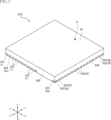
- FIG. 1 is a perspective view showing a semiconductor device according to a first embodiment of the present disclosure.
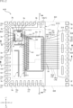
- FIG. 2 is a plan view showing the semiconductor device of FIG. 1, seen through a sealing resin.
- FIG. 3 is a bottom view showing the semiconductor device of FIG.
- FIG. 4 is a cross-sectional view taken along line IV-IV in FIG.
- FIG. 5 is a cross-sectional view taken along line VV in FIG.
- FIG. 6 is a cross-sectional view taken along line VI-VI in FIG.
- FIG. 7 is a partially enlarged view of FIG.
- FIG. 8 is a partially enlarged view of FIG.
- FIG. 9 is a plan view showing the die pad portion.
- FIG. 10 is a plan view showing a process according to the method for manufacturing the semiconductor device according to the first embodiment.
- FIG. 10 is a plan view showing a process according to the method for manufacturing the semiconductor device according to the first embodiment.
- FIG. 10 is a plan view showing a process according to the method for
- FIG. 11 is a plan view showing a process according to the method for manufacturing the semiconductor device according to the first embodiment.
- FIG. 12 is a plan view showing a process according to the method for manufacturing the semiconductor device according to the first embodiment.
- FIG. 13 is a partial enlarged plan view showing a semiconductor device according to a first modification of the first embodiment.
- FIG. 14 is a partial enlarged plan view showing a semiconductor device according to a second modification of the first embodiment.
- FIG. 15 is a partial enlarged plan view showing a semiconductor device according to a third modification of the first embodiment.
- FIG. 16 is a partial enlarged plan view showing a semiconductor device according to a fourth modification of the first embodiment.
- FIG. 17 is a partial enlarged plan view showing a semiconductor device according to a fifth modification of the first embodiment.
- FIG. 12 is a plan view showing a process according to the method for manufacturing the semiconductor device according to the first embodiment.
- FIG. 13 is a partial enlarged plan view showing a semiconductor device according to a first modification
- FIG. 18 is a partial enlarged plan view showing a semiconductor device according to a sixth modification of the first embodiment.
- FIG. 19 is a cross-sectional view showing a semiconductor device according to the second embodiment.
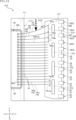
- FIG. 20 is a plan view showing the semiconductor device according to the third embodiment, seen through a sealing resin.
- FIG. 21 is a plan view showing a semiconductor device according to a first modification of the third embodiment, seen through a sealing resin.
- FIG. 22 is a plan view showing the semiconductor device according to the fourth embodiment, seen through a sealing resin.
- an object A is formed on an object B" and “an object A is formed on an object B” include “an object A is formed directly on an object B” and “an object A is formed on an object B with another object interposed between the object A and the object B” unless otherwise specified.
- an object A is disposed on an object B” and “an object A is disposed on an object B” include “an object A is disposed directly on an object B” and “an object A is disposed on an object B with another object interposed between the object A and the object B" unless otherwise specified.
- an object A is located on an object B includes “an object A is located on an object B in contact with an object B” and “an object A is located on an object B with another object interposed between the object A and the object B” unless otherwise specified.
- an object A overlaps an object B when viewed in a certain direction includes “an object A overlaps the entirety of an object B” and “an object A overlaps a part of an object B.”
- First embodiment: 1 to 9 show an example of a semiconductor device according to the present disclosure.
- the semiconductor device A10 of this embodiment includes a lead 1, a lead 2, a plurality of leads 3, semiconductor elements 61 and 62, a plurality of wires 7, and a sealing resin 8.
- the semiconductor device A10 is used in a gate driver circuit of an inverter device of an electric vehicle or a hybrid vehicle, for example.
- the semiconductor device A10 amplifies a control signal input from the outside and outputs it to a switching element (not shown).
- the use and function of the semiconductor device A10 are not limited.
- the package format of the semiconductor device A10 is a QFN type. However, the package format of the semiconductor device A10 is not limited to the QFN type.
- FIG. 1 is a perspective view of the semiconductor device A10.
- FIG. 2 is a plan view of the semiconductor device A10.
- the external shape of the sealing resin 8 is shown by imaginary lines (two-dot chain lines) through the sealing resin 8.
- FIG. 3 is a bottom view of the semiconductor device A10.
- FIG. 4 is a cross-sectional view taken along line IV-IV in FIG. 2.
- FIG. 5 is a cross-sectional view taken along line V-V in FIG. 2.
- FIG. 6 is a cross-sectional view taken along line VI-VI in FIG. 2.
- FIG. 7 is a partially enlarged view of FIG. 2.
- FIG. 8 is a partially enlarged view of FIG. 2.
- FIG. 9 is a plan view showing the die pad portion 11 (described later) of the lead 1.
- the semiconductor device A10 has a rectangular shape when viewed in the thickness direction (plan view).
- an example of the thickness direction (plan view direction) of the semiconductor device A10 is the thickness direction z
- the direction along one side of the semiconductor device A10 perpendicular to the thickness direction z (the left-right direction in Figures 2 and 3) is the first direction x
- the direction perpendicular to the thickness direction z and the first direction x (the up-down direction in Figures 2 and 3) is the second direction y.
- one side of the thickness direction z (the upper side in Figures 4 to 6) is the first side z1
- the other side is the second side z2.
- One side of the first direction x (the left side in Figures 1 and 2) is the first side x1, and the other side (the right side in Figures 1 and 2) is the second side x2.
- One side of the second direction y (the upper side in Figure 2) is the first side y1, and the other side (the lower side in Figure 2) is the second side y2.
- the shape and dimensions of the semiconductor device A10 are not limited.
- Lead 1, lead 2, and multiple leads 3 are members that form a conductive path between the semiconductor elements 61, 62 and the wiring board on which the semiconductor device A10 is mounted. Note that some of the multiple leads 3 are not conductive to the semiconductor elements 61, 62.
- the leads 1 to 3 are formed, for example, by subjecting a metal plate to etching or punching processing.
- the leads 1 to 3 are made of metal, preferably either Cu or Ni, or an alloy thereof, or 42 alloy. In this embodiment, an example will be described in which the leads 1 to 3 are made of Cu.
- the thickness of the leads 1 to 3 is, for example, 0.08 to 0.3 mm, and in this embodiment, it is about 0.2 mm.
- lead 1 is disposed toward the first side x1 in the first direction x of the semiconductor device A10, and spreads over the entire semiconductor device A10 in the second direction y.
- Lead 2 is spaced apart from lead 1 and disposed toward the second side x2 in the first direction x of the semiconductor device A10.
- Each lead 3 is spaced apart from leads 1 and 2, and is also spaced apart from each other, and disposed at either both ends of the semiconductor device A10 in the first direction x or both ends of the semiconductor device A10 in the second direction y.
- lead 1 is larger than lead 2
- each lead 3 is larger than lead 2.
- the lead 1 supports the semiconductor elements 61, 62 and has a die pad portion 11 and multiple terminal portions 12.
- the die pad portion 11 has a semiconductor element 61 and a semiconductor element 62 mounted thereon.
- the die pad portion 11 is located toward the first side x1 in the first direction x of the semiconductor device A10, in the center in the second direction y, and is generally rectangular when viewed in the thickness direction z.
- the die pad portion 11 has a main surface 111, a back surface 112, and a back surface recess 113.
- the main surface 111 and the back surface 112 face opposite each other in the thickness direction z.
- the main surface 111 faces the first side z1 in the thickness direction z.
- the main surface 111 is a surface on which the semiconductor elements 61 and 62 are mounted. As shown in FIG. 9, the main surface 111 has an edge 111a.
- the edge 111a is an edge extending in the second direction y on the first side x1 of the main surface 111 in the first direction x.
- the back surface 112 faces the second side z2 in the thickness direction z.
- the back surface 112 is exposed from the sealing resin 8 and becomes the back surface terminal.
- the back surface side recess 113 is a portion of the die pad portion 11 recessed from the back surface 112 to the first side z1 in the thickness direction z.
- the thickness (dimension in the thickness direction z) of the portion of the die pad portion 11 where the back surface side recess 113 is located is approximately half the thickness of the portion where the back surface 112 is located.
- the back surface side recess 113 is formed, for example, by half-etching from the second side z2 in the thickness direction z. As shown in FIG. 3, the back surface side recess 113 is disposed around the back surface 112. The back surface side recess 113 is not exposed from the sealing resin 8 and is covered by the sealing resin 8.
- the shape of the die pad portion 11 is not limited.
- the die pad portion 11 does not need to have the back surface side recess 113.
- the die pad portion 11 has an opening 4. Note that in Figs. 2, 8, and 9, the opening 4 is hatched relatively finely for ease of understanding.
- the opening 4 is an opening having an open end on the main surface 111, and in this embodiment, is a recess recessed from the main surface 111 to the second side z2 in the thickness direction z.
- the depth of the opening 4 (dimension in the thickness direction z) is approximately half the thickness of the die pad portion 11 (the distance between the main surface 111 and the back surface 112 in the thickness direction z).
- the opening 4 is formed, for example, by a half-etching process from the first side z1 in the thickness direction z. As shown in Fig. 9, the opening 4 includes openings 41 to 45.
- the opening 41 is located between the semiconductor element 62 shown by the imaginary line (two-dot chain line) in FIG. 9 and the edge 111a in the first direction x, and extends in the second direction y. In this embodiment, both ends of the opening 41 in the second direction y are located inside the outer edge of the main surface 111 when viewed in the thickness direction z.
- the opening 42 is connected to the end of the first side y1 of the opening 41 in the second direction y and extends to the first side x1 in the first direction x. In other words, the opening 42 is located on the first side x1 of the opening 41 in the first direction x.
- both ends of the opening 42 in the first direction x are located inside the outer edge of the main surface 111 when viewed in the thickness direction z.
- the semiconductor element 61 shown by the imaginary line (two-dot chain line) in FIG. 9 is disposed on the first side y1 of the opening 42 in the second direction y.
- the portion of the opening 4 that is composed of the opening 41 and the opening 42 is L-shaped when viewed in the thickness direction z.
- the opening 43 is located between the semiconductor element 62 and the opening 41 in the first direction x, and extends in the second direction y. In this embodiment, as viewed in the thickness direction z, both ends of the opening 43 in the second direction y are located inside the outer edge of the main surface 111.
- the opening 44 is connected to an end of the first side y1 of the opening 43 in the second direction y, and extends to the first side x1 in the first direction x. That is, the opening 44 is located on the first side x1 of the opening 43 in the first direction x.
- the opening 44 is also located between the semiconductor element 61 and the opening 42 in the second direction y.
- both ends of the opening 44 in the first direction x are located inside the outer edge of the main surface 111.
- the opening 45 is connected to an end of the first side y1 of the opening 43 in the second direction y, and extends to the first side y1 in the second direction y. That is, the opening 45 is located on the first side y1 of the opening 43 in the second direction y.
- both ends of the opening 45 in the second direction y are located inside the outer edge of the main surface 111 when viewed in the thickness direction z.
- the portion of the opening 4 that is composed of the openings 43, 44, and 45 is T-shaped when viewed in the thickness direction z.
- the main surface 111 of the die pad portion 11 includes a first region 51, a second region 52, and a third region 53.
- the first region 51, the second region 52, and the third region 53 are indicated by imaginary lines (two-dot chain lines) and are relatively coarsely hatched.
- the first region 51 is a region sandwiched between the openings 41 and 42 and the openings 43 and 44.
- the first region 51 is located on the first side x1 of the semiconductor element 62 in the first direction x, and is a region to which the wire 7 (wire 73 described later) is bonded, as shown in FIG. 2.
- the first region 51 may be plated.
- the plating layer formed by the plating process is made of a metal containing Ag, for example.
- the plating layer protects the lead 1 from impact during wire bonding of the wire 73 while increasing the bonding strength of the wire 73.
- the second region 52 is a region on the second side x2 of the openings 43 and 45 in the first direction x.
- the second region 52 is a region where a semiconductor element 62 is mounted, as shown in FIG. 2.
- the third region 53 is a region on the first side x1 of the opening 45 in the first direction x and on the first side y1 of the opening 44 in the second direction y.
- the third region 53 is located on the first side x1 from the center of the main surface 111 of the die pad portion 11 in the first direction x, and on the first side y1 from the center in the second direction y.
- the third region 53 is a region where a semiconductor element 61 is mounted, as shown in FIG. 2.
- the first region 51, the second region 52, and the third region 53 are regions partitioned by the openings 4.
- the openings 43 partition the first region 51 and the second region 52.
- the openings 44 partition the first region 51 and the third region 53.
- the openings 45 partition the second region 52 and the third region 53. Note that the shape and arrangement of the openings 4 are not limited to those described above, and the shapes and arrangement of the first region 51, the second region 52, and the third region 53 are not limited to those described above.
- the multiple terminals 12 are joined to the wiring board when the semiconductor device A10 is mounted on the wiring board. Each terminal 12 is connected to the die pad portion 11 and has a substantially rectangular shape when viewed in the thickness direction z.
- the multiple terminals 12 include six terminals 12a, two terminals 12b, eight terminals 12c, and terminals 12d and 12e.
- the six terminals 12a are connected to the first side x1 of the die pad portion 11 in the first direction x and are arranged along the second direction y near the second side y2 of the second direction y.
- the six terminals 12a overlap the opening 4 (opening 41) when viewed in the first direction x.
- the two terminals 12b are connected to the first side y1 of the die pad portion 11 in the second direction y and are arranged along the second direction y near the second side x2 of the first direction x.
- the eight terminals 12c are connected to the second side y2 in the second direction y of the die pad portion 11 and are arranged along the first direction x.
- the terminal 12d is connected to a corner of the first side y1 in the second direction y on the first side x1 in the first direction x of the die pad portion 11.
- the terminal 12e is connected to a corner of the second side y2 in the second direction y on the first side x1 in the first direction x of the die pad portion 11.
- Each terminal portion 12 has a main surface 121, a back surface 122, and an end surface 123.
- the main surface 121 and the back surface 122 face opposite each other in the thickness direction z.
- the main surface 121 faces the first side z1 in the thickness direction z.
- the main surface 121 and the main surface 111 of the die pad portion 11 are flush with each other.
- the back surface 122 faces the second side z2 in the thickness direction z.
- the back surface 122 and the back surface 112 of the die pad portion 11 are spaced apart as shown in FIG. 3, and are positioned at the same (or approximately the same) position in the thickness direction z.
- the end surface 123 is perpendicular to the main surface 121 and the back surface 122, and is connected to the main surface 121 and the back surface 122.
- the terminal portion 12d and the terminal portion 12e each have two end surfaces 123.
- the end surfaces 123 are formed by singulation during the cutting process in the manufacturing process.
- the end surface 123 and the back surface 122 are exposed from the sealing resin 8 and connected to form a terminal (see FIG. 5). Note that there are no limitations on the shape, arrangement, or number of the terminal portion 12.
- the lead 2 is arranged at a distance from the lead 1 on the second side x2 in the first direction x.
- the die pad portion 11 of the lead 1 and the lead 2 are arranged side by side in the first direction x.
- the lead 2 is electrically connected to the semiconductor element 62 by a plurality of wires 7 (a plurality of wires 74 described below).
- the lead 2 has a pad portion 21 and a plurality of terminal portions 22.
- the pad portion 21 is bonded to a plurality of wires 74.
- the pad portion 21 has a main surface 211, a back surface 212, and a through hole 213.
- the main surface 211 and the back surface 212 face opposite each other in the thickness direction z.
- the main surface 211 faces a first side z1 in the thickness direction z.
- the main surface 211 is a surface to which the plurality of wires 74 are bonded.
- the main surface 211 may be plated.
- the plating layer formed by the plating process is made of a metal containing Ag, for example. The plating layer protects the lead 2 from impact during wire bonding of the wire 74 while increasing the bonding strength of the wire 74.
- the back surface 212 faces a second side z2 in the thickness direction z.
- the back surface 212 is covered with a sealing resin 8.
- the thickness of the pad portion 21 (dimension in the thickness direction z) is about half the thickness of the die pad portion 11 and is about the same as the thickness of a portion of the die pad portion 11 where the back surface recess 113 is located.
- the pad portion 21 is formed, for example, by half-etching from the second side z2 in the thickness direction z.
- the through holes 213 are holes that penetrate the pad portion 21 in the thickness direction z.
- the through holes 213 make it easier for the material of the sealing resin 8 to be filled on the back surface 212 side of the pad portion 21 during the process of forming the sealing resin 8 in the manufacturing process of the semiconductor device A10.
- the pad portion 21 has four approximately rectangular through holes 213 that are elongated in the second direction y arranged in the second direction y.
- the shape, number, and arrangement of the through holes 213 are not limited. Furthermore, the pad portion 21 does not need to have through holes 213.
- the multiple terminal portions 22 are joined to the wiring board when the semiconductor device A10 is mounted on the wiring board.
- Each terminal portion 22 is connected to the second side x2 of the pad portion 21 in the first direction x, and is substantially rectangular when viewed in the thickness direction z.
- twelve terminal portions 22 are arranged at equal intervals along the second direction y.
- Each terminal portion 22 has a main surface 221, a back surface 222, and an end surface 223.
- the main surface 221 and the back surface 222 face opposite each other in the thickness direction z.
- the main surface 221 faces the first side z1 in the thickness direction z.
- the main surface 221 and the main surface 211 of the pad portion 21 are flush with each other.
- the back surface 222 faces the second side z2 in the thickness direction z.
- the distance Ly between the back surface 222 of the terminal portion 22 of the lead 2 and the back surface 112 of the die pad portion 11 is sufficiently large, and is 2.2 mm or more so that insulation breakdown does not occur even with a potential difference of 600 V.
- the distance between the back surface 222 and the back surface 112 is not limited to this.
- the end surface 223 is a surface that is perpendicular to the main surface 221 and the back surface 222 and connects to the main surface 221 and the back surface 222.
- the end surface 223 is formed by singulation during the cutting process in the manufacturing process.
- the end surface 223 and the back surface 222 are exposed from the sealing resin 8 and connected to form a terminal (see Figures 4 and 5).
- the shape, arrangement position, and number of the terminal portion 22 are not limited.
- the multiple leads 3 form a conductive path between the semiconductor elements 61, 62 and the wiring board on which the semiconductor device A10 is mounted.
- the multiple leads 3 also include so-called dummy leads that are not conductive to the semiconductor elements 61, 62.
- Each lead 3 has a pad portion 31 and a terminal portion 32.
- the pad portion 31 is a portion for bonding the wire 7 (wire 71 described later).
- the pad portion 31 may or may not have the wire 71 bonded thereto.
- the pad portion 31 has a main surface 311 and a back surface 312.
- the main surface 311 and the back surface 312 face opposite each other in the thickness direction z.
- the main surface 311 faces the first side z1 in the thickness direction z.
- the main surface 311 is the surface to which the wire 71 is bonded.
- the main surface 311 may be plated.
- the plating layer formed by the plating process is made of a metal containing Ag, for example. The plating layer protects the lead 3 from impact during wire bonding of the wire 71 while increasing the bonding strength of the wire 71.
- the plating layer may be formed only on the lead 3 to which the wire 71 is bonded.
- the back surface 312 faces the second side z2 in the thickness direction z.
- the back surface 312 is covered with a sealing resin 8.
- the thickness of the pad portion 31 (dimension in the thickness direction z) is about half the thickness of the die pad portion 11, and is about the same as the thickness of the portion of the die pad portion 11 where the back surface side recess 113 is located.
- the pad portion 31 is formed, for example, by half-etching processing from the second side z2 in the thickness direction z.
- the terminal portion 32 is joined to the wiring board when the semiconductor device A10 is mounted on the wiring board.
- the terminal portion 32 is connected to the pad portion 31 and has a substantially rectangular shape when viewed in the thickness direction z.
- the terminal portion 32 has a main surface 321, a back surface 322, and an end surface 323.
- the main surface 321 and the back surface 322 face opposite each other in the thickness direction z.
- the main surface 321 faces the first side z1 in the thickness direction z.
- the main surface 321 and the main surface 311 of the pad portion 31 are flush with each other.
- the wire 71 may be joined to the main surface 321 of the terminal portion 32.
- the back surface 322 faces the second side z2 in the thickness direction z.
- the end surface 323 is perpendicular to the main surface 321 and the back surface 322 and is connected to the main surface 321 and the back surface 322.
- the end surface 323 is formed by singulation in a cutting process in the manufacturing process.
- the end surface 323 and the back surface 322 are exposed from the sealing resin 8 and connected to form a terminal (see FIG. 4).
- the shape of the terminal portion 32 is not limited.
- the multiple leads 3 include multiple leads 3a, multiple leads 3b, lead 3c, lead 3e, a pair of leads 3f, and a pair of leads 3g.
- the multiple leads 3 include seven leads 3a.
- the number of leads 3a is not limited.
- the multiple leads 3a are arranged near the first side y1 in the second direction y of the end of the first side x1 in the first direction x of the semiconductor device A10.
- the multiple leads 3a are arranged on the first side x1 in the first direction x of the die pad portion 11 along the second direction y between the terminal portion 12a and the terminal portion 12d in the second direction y.
- the multiple leads 3 include seven leads 3b.
- the number of leads 3b is not limited.
- the multiple leads 3b are arranged near the first side x1 in the first direction x of the end of the first side y1 in the second direction y of the semiconductor device A10.
- the multiple leads 3b are arranged on the first side y1 in the second direction y of the die pad portion 11 along the first direction x between the terminal portion 12b and the terminal portion 12d in the first direction x.
- the multiple leads 3a and the multiple leads 3b are arranged so as to be electrically connected to the semiconductor element 61 via the wires 71.
- most of the multiple leads 3a and the multiple leads 3b are electrically connected to the semiconductor element 61, but some are not electrically connected to the semiconductor element 61. It is not limited which of the multiple leads 3a and the multiple leads 3b are electrically connected to the semiconductor element 61, or which electrode 611 (described later) of the semiconductor element 61 they are electrically connected to.
- each of the pads 31 of the multiple leads 3a and the multiple leads 3b extends toward the element center 61c, which is the center of the semiconductor element 61, when viewed in the thickness direction z.
- the multiple leads 3 include one lead 3c and one lead 3e.
- the number of leads 3c and 3e is not limited.
- Lead 3c is arranged on the first side x1 of the die pad portion 11 in the first direction x, between terminal portion 12a and terminal portion 12e in the second direction y.
- Lead 3e is arranged on the second side y2 of the die pad portion 11 in the second direction y, between terminal portion 12c and terminal portion 12e in the first direction x.
- Leads 3c and 3e are so-called dummy leads.
- the multiple leads 3 include a pair of leads 3f and a pair of leads 3g.
- the pair of leads 3g are arranged on the first side y1 and the second side y2 of the lead 2 in the second direction y, one each.
- One lead 3g is arranged at a corner on the first side y1 of the second direction y on the second side x2 of the first direction x of the semiconductor device A10, and the other lead 3g is arranged at a corner on the second side y2 of the second direction y on the second side x2 of the first direction x of the semiconductor device A10.
- the multiple leads 3 do not have to include the lead 3g.
- the pair of leads 3f are arranged on the first side y1 and the second side y2 of the lead 2 in the second direction y, one each.
- Each lead 3f is arranged between the lead 2 and each lead 3g in the second direction y. Note that the number of leads 3f is not limited.
- the leads 3f and the leads 3g are so-called dummy leads.
- a plating layer containing, for example, Sn may be disposed on the surfaces of the leads 1 to 3 that are exposed from the sealing resin 8.
- the material of the plating layer is not limited.
- the plating layer improves the adhesion of solder to the exposed surfaces while preventing erosion of the exposed parts due to solder bonding.
- the shapes and arrangements of the leads 1 to 3 are not limited to those described above.
- the semiconductor element 61 and the semiconductor element 62 are elements that perform the electrical functions of the semiconductor device A10.
- the semiconductor element 62 is a switching element.
- the semiconductor element 62 is a HEMT (High Electron Mobility Transistor) using gallium nitride (GaN).
- the semiconductor element 62 may use a nitride semiconductor other than GaN.
- the semiconductor element 62 may also be an IGBT (Insulated Gate Bipolar Transistor), a MOSFET (Metal Oxide Semiconductor Field Effect Transistor), a bipolar transistor, or the like.
- the semiconductor element 62 has an element main surface 62a, an element back surface 62b, a plurality of first electrodes 621, a second electrode 622, and a plurality of third electrodes 623.
- the element principal surface 62a and the element back surface 62b face opposite each other in the thickness direction z.
- the element principal surface 62a faces the first side z1 in the thickness direction z
- the element back surface 62b faces the second side z2 in the thickness direction z.
- a plurality of first electrodes 621, a second electrode 622, and a plurality of third electrodes 623 are arranged on the element principal surface 62a.
- the plurality of first electrodes 621 are source electrodes and are arranged side by side along the second direction y on the side of the first side x1 of the first direction x of the element principal surface 62a.
- the second electrode 622 is a gate electrode and is arranged side by side along the second direction y on the side of the first side y1 of the element principal surface 62a.
- the plurality of third electrodes 623 are drain electrodes and are arranged side by side at equal intervals along the second direction y on the side of the second side x2 of the element principal surface 62a in the first direction x.
- Other electrodes are also arranged on the element principal surface 62a.
- the layout of the electrodes 621 to 623 is not limited.
- the semiconductor element 62 has its element back surface 62b bonded to the main surface 111 of the die pad portion 11 via a bonding member 65.
- the bonding member 65 is, for example, Ag paste.
- the bonding member 65 may be a conductive bonding material such as solder or sintered silver bonding material, or may be an insulating bonding material.
- the semiconductor element 62 is disposed in the second region 52 of the main surface 111, that is, on the second side x2 in the first direction x of the openings 43 and 44.
- Semiconductor element 61 is a drive element that drives semiconductor element 62.
- Semiconductor element 61 generates a drive signal based on a control signal input from the outside and outputs it to semiconductor element 62.
- Semiconductor element 61 also controls the drive signal based on a source sense signal input from semiconductor element 62.
- Semiconductor element 61 has an element main surface 61a, an element back surface 61b, and a number of electrodes 611.
- the element principal surface 61a and the element back surface 61b face in opposite directions in the thickness direction z.
- the element principal surface 61a faces a first side z1 in the thickness direction z
- the element back surface 61b faces a second side z2 in the thickness direction z.
- a plurality of electrodes 611 are arranged on the element principal surface 61a. Note that the function and arrangement of each electrode 611 are not limited.
- the semiconductor element 61 has an element back surface 61b bonded to the main surface 111 of the die pad portion 11 via a bonding member 65.
- the semiconductor element 61 is disposed in the third region 53 of the main surface 111, that is, on the first side x1 of the opening 45 in the first direction x and on the first side y1 of the opening 44 in the second direction y.
- the semiconductor element 61 is disposed on the first side x1 relative to the semiconductor element 62 in the first direction x and on the first side y1 relative to the semiconductor element 62 in the second direction y.
- the element center 61c which is the center of the semiconductor element 61 as viewed in the thickness direction z, is located on the first side y1 from the center of the main surface 111 of the die pad portion 11 in the second direction y, and is located on the first side x1 from the center of the main surface 111 in the first direction x.
- each wire 7 is, for example, but not limited to, Cu, Au, Ag, Al, or an alloy containing any of these.
- the multiple wires 7 each include multiple wires 71, 72, 73, and 74.
- the multiple wires 71 form a conductive path between the semiconductor element 61 and the multiple leads 3.
- Each wire 71 is conductively joined to one of the electrodes 611 of the semiconductor element 61 and the main surface 311 of the pad portion 31 of one of the multiple leads 3a or the multiple leads 3b. This allows the semiconductor element 61 to receive signals from the outside and output signals to the outside via the multiple leads 3 and wires 71. Since the pad portions 31 of both the multiple leads 3a and the multiple leads 3b extend toward the element center 61c of the semiconductor element 61 when viewed in the thickness direction z, each wire 71 can be formed so as not to overlap other leads 3 adjacent to the lead 3 to which the wire 71 is joined when viewed in the thickness direction z.
- the multiple wires 72 form a conductive path between the semiconductor element 61 and the semiconductor element 62.
- One wire 72 is conductively joined to one of the electrodes 611 of the semiconductor element 61 and the second electrode 622 of the semiconductor element 62.
- the semiconductor element 61 outputs a drive signal to the second electrode 622 via the wire 72.
- the other wires 72 are conductively joined to one of the electrodes 611 of the semiconductor element 61 and one of the electrodes of the semiconductor element 62.
- the semiconductor element 61 receives a source sense signal via the wire 72 joined to the first electrode 621 (source electrode) of the semiconductor element 62.
- the semiconductor element 61 also inputs and outputs signals to and from the semiconductor element 62 via the other wires 72.
- the multiple wires 73 form a conductive path between the semiconductor element 62 and the die pad portion 11.
- Each wire 73 is conductively joined to one of the first electrodes 621 of the semiconductor element 62 and the main surface 111 of the die pad portion 11.
- the lead 1 is conductively connected to the first electrode 621 (source electrode) of the semiconductor element 62 and functions as a source terminal.
- each wire 73 is joined to the first region 51 of the main surface 111.
- the multiple wires 74 form a conductive path between the semiconductor element 62 and the leads 2.
- Each wire 74 is conductively joined to one of the third electrodes 623 of the semiconductor element 62 and the main surface 211 of the pad portion 21 of the lead 2.
- the lead 2 is conductively connected to the third electrode 623 (drain electrode) of the semiconductor element 62 and functions as a drain terminal.
- the multiple wires 74 are arranged side by side in the second direction y.
- the multiple wires 74 include wires 741, 742, 743, 74x1, and 74x2.
- the wire 741 is disposed on the first side y1 in the second direction y.
- the wire 741 has a joint 741a joined to the lead 2.
- the wire 742 is disposed adjacent to the second side y2 of the wire 741.
- the wire 742 has a joint 742a joined to the lead 2.
- the wire 743 is disposed adjacent to the second side y2 of the wire 742.
- the wire 743 has a joint 743a joined to the lead 2.
- the wire 74x1 is disposed on the second side y2 in the second direction y.
- the wire 74x1 has a joint 74x1a joined to the lead 2.
- the wire 74x2 is disposed adjacent to the first side y1 of the wire 74x1.
- Wire 74x2 has a joint 74x2a that is joined to lead 2.
- the distance L1 between joint 741a and joint 742a is greater than the distance Lx between joint 74x1a and joint 74x2a.
- the distance L2 between joint 742a and joint 743a is greater than the distance Lx.
- the distance L1 is greater than the distance L2.
- the distance between the joints of wires 74 other than wires 741 to 743 and lead 2 is approximately the same as the distance Lx. In other words, the spacing between adjacent wires 74 of each wire 74 is wider only between wire 741 and wire 742, and between wire 742 and wire 743, and is equal apart.
- the distance Lx is approximately the same as the spacing between the third electrodes 623 of the semiconductor element 62, and the wires 74, other than the wires 741 and 742, extend parallel (or approximately parallel) to the first direction x when viewed in the thickness direction z.
- the wires 741 and 742 extend in a direction inclined with respect to the first direction x when viewed in the thickness direction z (located closer to the first side y1 than the second side x2) because the distances L1 and L2 are greater than the distance Lx.
- the length of the wires 74 other than the wires 741 and 742 is, for example, 2.65 mm.
- the length varies depending on the distance between the semiconductor element 62 and the pad portion 21 of the lead 2. It is desirable that the length be as short as possible, but if the dimension of the pad portion 21 in the first direction x is made too large, the strength of the pad portion 21 decreases, and there is a high possibility that the resin material of the sealing resin 8 will not be properly filled on the back surface 212 side of the pad portion 21.
- the length of wires 741 and 742 is longer than the other wires 74 by the amount of inclination.
- All of the multiple wires 74 have the same (or approximately the same) maximum distance H (see Figures 4 and 5) from the main surface 111 of the die pad portion 11 in the thickness direction z, and overlap each other when viewed in the y direction.
- the resin material of the sealing resin 8 flows along the second direction y from the first side y1 to the second side y2 in the second direction y, as shown by the dashed arrow 89 in Figure 7.
- each wire 74 is curved so that the center bulges toward the second side y2 in the second direction y.
- the wire 741 Since the wire 741 is disposed on the furthest first side y1 in the second direction y (the front side in the direction in which the resin material flows), the wire flow is larger than that of the other wires 74. Therefore, the wire 741 is curved larger than the other wires 74. Since the flow of the resin material is suppressed by the wire 741, the wire flow of the wire 742 is suppressed more than that of the wire 741. Similarly, the wires 74 located closer to the second side y2 in the second direction y are less affected by the flow of the resin material, and therefore wire sweep is more mitigated.
- the distance between wires 741 and 742 and the distance between wires 742 and 743 are larger than the distance between any other two adjacent wires 74. Also, by making distance L1 larger than distance L2, the distance between wires 741 and 742 is larger than the distance between wires 742 and 743.
- distance L1 and distance L2 are three times or more the distance Lx. Note that distance L1 and distance L2 are not limited and are set appropriately based on experiments or simulations.
- the degree of wire sweep of wires 741 and 742 varies depending on the material, length, wire diameter, distance Lx, etc. of wires 741 and 742. In this embodiment, when wires 741 and 742 are made of PdCu, have a length of about 2.75 mm, a wire diameter of 30 ⁇ m, and distance Lx of about 150 ⁇ m, distance L1 and distance L2 are set so that wires 741 and 742 will not come into contact with adjacent wires 74 even if they sweep by about 10%.
- the sealing resin 8 covers a portion of each of the leads 1 to 3, the semiconductor elements 61 and 62, and the wires 7.
- the sealing resin 8 has electrical insulation properties.
- the sealing resin 8 is made of a material that contains, for example, black epoxy resin. Note that the material of the sealing resin 8 is not limited.
- the sealing resin 8 has a resin main surface 81, a resin back surface 82, and four resin side surfaces 83.
- the resin main surface 81 and the resin back surface 82 face opposite each other in the thickness direction z.
- the resin main surface 81 faces the first side z1 in the thickness direction z
- the resin back surface 82 faces the second side z2 in the thickness direction z.
- the four resin side surfaces 83 are each perpendicular to the resin main surface 81 and the resin back surface 82, connect the resin main surface 81 and the resin back surface 82, and face outward in the first direction x or the second direction y.
- Each resin side surface 83 is formed by singulation in the cutting process in the manufacturing process.
- the four resin side surfaces 83 include a first resin side surface 831, a second resin side surface 832, a third resin side surface 833, and a fourth resin side surface 834.
- the first resin side surface 831 and the second resin side surface 832 face opposite each other in the second direction y.
- the first resin side surface 831 is a surface that is disposed on the first side y1 of the second direction y and faces the first side y1
- the second resin side surface 832 is a surface that is disposed on the second side y2 of the second direction y and faces the second side y2.
- the third resin side surface 833 and the fourth resin side surface 834 face opposite each other in the first direction x.
- the third resin side surface 833 is a surface that is disposed on a first side x1 in the first direction x and faces the first side x1
- the fourth resin side surface 834 is a surface that is disposed on a second side x2 in the first direction x and faces the second side x2.
- Each end face 123 of the lead 1 facing the first side x1 in the first direction x and each end face 323 of the lead 3a and lead 3c are exposed from the third resin side 833 and are flush with the third resin side face 833.
- Each end face 123 and each end face 323 exposed from the third resin side face 833 are spaced apart from each other and arranged at equal intervals along the second direction y.
- Each end face 123 of the lead 1 facing the first side y1 in the second direction y, each end face 323 of each lead 3b, and each end face 323 of the lead 3g facing the first side y1 are exposed from the first resin side face 831 and are flush with the first resin side face 831.
- Each end face 123 and each end face 323 of each lead 3b exposed from the first resin side face 831 are spaced apart from each other and arranged at equal intervals along the first direction x.
- Each end face 123 of the lead 1 facing the second side y2 in the second direction y, the end face 323 of the lead 3e, and the end face 323 of the lead 3g facing the second side y2 are exposed from the second resin side face 832 and are flush with the second resin side face 832.
- Each end face 123 exposed from the second resin side face 832 and the end face 323 of each lead 3e are spaced apart from each other and arranged at equal intervals along the first direction x.
- Each end face 223 of each terminal portion 22 of the lead 2, the end face 323 of each lead 3f, and the end face 323 of each lead 3g facing the second side x2 are exposed from the fourth resin side face 834 and are flush with the fourth resin side face 834.
- Each end face 223 and each end face 323 exposed from the fourth resin side face 834 are spaced apart from each other and arranged at equal intervals along the second direction y.
- the back surface 112 of the die pad portion 11 of lead 1 and the back surface 122 of each terminal portion 12, the back surface 222 of each terminal portion 22 of lead 2, and the back surface 322 of each terminal portion 32 of each lead 3 are exposed from the resin back surface 82 and are flush with the resin back surface 82.
- Figures 10 to 12 are plan views showing steps involved in the method for manufacturing the semiconductor device A10. Note that the x, y, and z directions shown in these figures are the same as those in Figures 1 to 9.
- the lead frame 9 (see FIG. 10) is prepared.
- the lead frame 9 is a plate-shaped material.
- the base material of the lead frame 9 is made of Cu.
- the lead frame 9 may be formed by subjecting a metal plate to an etching process or the like, or may be formed by subjecting a metal plate to a punching process.
- the semiconductor element 61 and the semiconductor element 62 are mounted on the main surface 111 of the die pad portion 11.
- the element back surface 61b of the semiconductor element 61 is joined to the main surface 111 of the die pad portion 11 via a joining member 65.
- the element back surface 62b of the semiconductor element 62 is joined to the main surface 111 of the die pad portion 11 via a joining member 65.
- Each wire 71 is conductively joined to one of the electrodes 611 of the semiconductor element 61 and one of the plurality of leads 3a or 3b.
- Each wire 72 is conductively joined to one of the electrodes 611 of the semiconductor element 61 and one of the electrodes of the semiconductor element 62.
- Each wire 73 is conductively joined to one of the first electrodes 621 of the semiconductor element 62 and the main surface 111 of the die pad portion 11.
- Each wire 74 is conductively joined to one of the third electrodes 623 of the semiconductor element 62 and the main surface 211 of the pad portion 21 of the lead 2.
- the wire 742 is joined such that the joint portion 742a is located at a distance L2 away from the joint portion 743a on the first side y1 in the second direction y.
- the wire 741 is joined such that the joint portion 741a is located at a distance L1 away from the joint portion 742a on the first side y1 in the second direction y.
- the sealing resin 8 is formed.
- the sealing resin 8 is formed by transfer molding.
- the lead frame 9 is placed in a mold, and a fluidized resin material is injected.
- the resin material is injected from the first side y1 to the second side y2 in the second direction y, as shown by the thick arrow in FIG. 12, and flows along the second direction y.
- This causes wire flow in the wires 74, which are particularly long, and each wire 74 is curved so that its center bulges toward the second side y2 in the second direction y. Since the wires 741 and 742 are arranged on the first side y1 in the second direction y (the front side in the direction in which the resin material flows), they are curved more than the other wires 74.
- the resin material is then solidified.
- the lead frame 9 and the resin material are cut into individual pieces by singulation. Through the steps described above, the semiconductor device A10 is manufactured.
- the wire 742 is joined at a position where the joint 742a is a distance L2 (>Lx) away from the joint 743a on the first side y1 in the second direction y.
- the wire 741 is joined at a position where the joint 741a is a distance L1 (>Lx) away from the joint 742a on the first side y1 in the second direction y.
- the sealing resin 8 forming process the fluidized resin material is injected from the first side y1 toward the second side y2 in the second direction y.
- the wires 741 and 742 have a larger wire sweep and are more curved than the other wires 74, but the distance between the wires 741 and 742 is larger than the other wires 74, so contact with the adjacent wires 74 is suppressed. As a result, the semiconductor device A10 can suppress contact between wires due to wire sweep.
- the wires 74 other than the wires 741 and 742 extend parallel (or approximately parallel) to the first direction x when viewed in the thickness direction z. Therefore, the wires 74 other than the wires 741 and 742 connect each third electrode 623 of the semiconductor element 62 to the lead 2 at the shortest distance. Therefore, the loss of power due to the electrical resistance of the wires 74 is suppressed, and the amount of wire material used is also suppressed.
- the wire 741 extends in a direction inclined with respect to the first direction x when viewed in the thickness direction z.
- the force applied to the wire 741 by the resin material is decomposed into a component parallel to the wire 741 and a component perpendicular to the wire 741.
- the perpendicular component that affects the wire flow is smaller than when the wire 741 is parallel to the first direction x, so the wire flow is suppressed.
- the semiconductor element 61 is mounted at a position shifted toward the first side y1 from the center in the second direction y of the main surface 111 of the die pad portion 11.
- the pad portions 31 of each lead 3a all extend toward the element center 61c when viewed in the thickness direction z. Therefore, the wire 71 joined to each lead 3a can be formed so as not to overlap with the other lead 3a adjacent to the lead 3a to which the wire 71 is joined when viewed in the thickness direction z. This allows the semiconductor device A10 to prevent each wire 71 from contacting the other adjacent lead 3a.
- the semiconductor element 61 is mounted at a position shifted toward the first side x1 from the center in the first direction x of the main surface 111 of the die pad portion 11.
- the pad portions 31 of each lead 3b all extend toward the element center 61c when viewed in the thickness direction z. Therefore, the wire 71 bonded to each lead 3b can be formed so as not to overlap other leads 3b adjacent to the lead 3b to which the wire 71 is bonded, as viewed in the thickness direction z. This allows the semiconductor device A10 to prevent each wire 71 from contacting the other adjacent leads 3b.
- the die pad portion 11 has an opening 4 which is a recess recessed from the main surface 111 to the second side z2 in the thickness direction z.
- the opening 4 is located between the first region 51 to which the wire 73 is bonded and the edge 111a in the first direction x, and includes an opening 41 extending in the second direction y.
- the opening 41 prevents the peeling that occurs at the edge 111a from progressing to the second side x2 in the first direction x. Since the opening 41 prevents the peeling from progressing to the first region 51, the semiconductor device A10 can suppress the peeling of the wire 73 from the die pad portion 11.
- the opening 4 includes an opening 42 which is connected to the end of the first side y1 in the second direction y of the opening 41 and extends to the first side x1 in the first direction x.
- the opening 42 prevents the peeling that occurs at the edge 111a from progressing to the first side y1 in the second direction y. Because the opening 42 prevents peeling from progressing to the first region 51 and the second region 52, the semiconductor device A10 can suppress peeling of the wire 73 from the die pad portion 11 and peeling of the semiconductor element 61 from the die pad portion 11.
- the opening 4 is located between the second region 52 on which the semiconductor element 62 is mounted and the first region 51 to which the wire 73 is bonded in the first direction x, and includes an opening 43 extending in the second direction y.
- the opening 43 can prevent the molten bonding member 65 from flowing to the first region 51. This can prevent the bonding member 65 from interfering with the bonding of the wire 73.
- the opening 43 prevents the sealing resin 8 from peeling from the die pad portion 11 toward the first side x1 in the first direction x, and can also contribute to preventing the wire 73 from peeling from the die pad portion 11.
- the opening 4 includes an opening 44 that is connected to the end of the first side y1 of the opening 43 in the second direction y and extends to the first side x1 in the first direction x.
- the opening 44 can suppress the molten bonding member 65 from flowing to the first region 51. This can suppress the bonding member 65 from interfering with the bonding of the wire 73.
- the opening 44 prevents the sealing resin 8 from peeling from the die pad portion 11 toward the second side y2 in the second direction y, and can also contribute to suppressing the peeling of the wire 73 from the die pad portion 11.
- the opening 4 includes an opening 45 that is connected to the end of the opening 43 on the first side y1 in the second direction y and extends to the first side y1 in the second direction y.
- the opening 45 suppresses the concentration of stress at the connection point between the opening 43 and the opening 44, and also strengthens the bond between the sealing resin 8 and the die pad portion 11.
- openings 43, 44, and 45 also serve to partition first region 51, second region 52, and third region 53, and to clearly indicate the positions for mounting semiconductor element 61 and semiconductor element 62.
- each end of the opening 4 is located inside the outer edge of the main surface 111 of the die pad portion 11. Therefore, the strength of the die pad portion 11 can be increased compared to when each end extends to the outer edge of the main surface 111. Furthermore, according to this embodiment, the opening 4 is a recess recessed from the main surface 111 toward the second side z2 in the thickness direction z. Therefore, the strength of the die pad portion 11 can be increased compared to when the opening 4 penetrates the die pad portion 11 in the thickness direction z.
- the distance between the back surface 112 of the die pad portion 11 and the back surface 222 of the terminal portion 22 of the lead 2 is sufficiently large. Therefore, electrical continuity between the back surfaces 112 and 222 due to dielectric breakdown is suppressed.
- the dimension of the pad portion 21 of the lead 2 in the first direction x is sufficiently large. This makes it possible to suppress the length of the wire 74 that electrically connects the semiconductor element 62 and the pad portion 21.
- the semiconductor device A10 is provided with leads 3c, 3e, 3f, and 3g, which are dummy leads. Therefore, the semiconductor device A10 has improved mounting reliability compared to a case where the semiconductor device A10 does not have the leads 3c, 3e, 3f, and 3g.
- the lead 1 is provided with terminal portions 12a, 12b, and 12c. Therefore, the semiconductor device A10 has improved heat dissipation and improved strength to support the die pad portion 11 compared to a case where the semiconductor device A10 has a lead spaced apart from the lead 1 instead of the terminal portions 12a, 12b, and 12c.
- distance L1 is greater than distance L2
- distance L1 and distance L2 may be approximately the same.
- distance L1 and distance L2 are greater than distance Lx, distance L1 may be smaller than distance L2.
- wire 741 has a greater wire sweep than wire 742, so it is desirable for distance L1 to be greater than distance L2.
- the opening 4 includes all of the openings 41 to 45, but this is not limited.
- the opening 4 may not include any of the openings 41 to 45.
- the opening 4 may include openings other than the openings 41 to 45.
- the manner in which the openings 41 to 45 are connected is also not limited.
- the openings 41 and 42 may not be connected and may be separated from each other, and the openings 43, 44, and 45 may not be connected and may be separated from each other.
- the arrangement of the openings 41 to 45 is also flexible. Any of the openings 41 to 45 may reach the outer edge of the main surface 111.
- Each of the openings 41 to 45 may be configured to be composed of a plurality of portions.
- the die pad portion 11 may not have an opening 4.
- each lead 3a and each lead 3b both extend toward the element center 61c when viewed in the thickness direction z, but this is not limited to this.
- the pad portion 31 of each lead 3a may extend to the second side x2 in the first direction x.
- the pad portion 31 of each lead 3b may extend to the second side y2 in the second direction y.
- the package format of the semiconductor device A10 the type and number of the semiconductor elements 61, 62 mounted thereon, and the shape, number, and arrangement of the leads 1 to 3.
- FIGS. 13 to 18 show modified examples of the semiconductor device A10 according to the first embodiment.
- elements that are the same as or similar to those in the above embodiment are given the same reference numerals as in the above embodiment, and duplicated explanations will be omitted.
- Fig. 13 is a diagram for explaining a semiconductor device A11 according to a first modification of the first embodiment.
- Fig. 13 is a partially enlarged plan view showing the semiconductor device A11, and corresponds to Fig. 7.
- the semiconductor device A11 differs from the semiconductor device A10 in the configuration of the multiple wires 74.
- the distance L2 between the joint 742a of the wire 742 and the joint 743a of the wire 743 is approximately the same as the distance Lx.
- the distance between adjacent wires 74 of each wire 74 is wider only between wires 741 and 742, and the distances are equal otherwise.
- Fig. 14 is a diagram for explaining a semiconductor device A12 according to a second modification of the first embodiment.
- Fig. 14 is a partially enlarged plan view showing the semiconductor device A12, and corresponds to Fig. 7.
- the semiconductor device A12 differs from the semiconductor device A10 in the configuration of the multiple wires 74.
- the multiple wires 74 further include a wire 744.
- the wire 744 is disposed adjacent to the second side y2 of the wire 743.
- the wire 744 has a joint 744a joined to the lead 2.
- the distance L3 between the joints 743a and 744a is greater than the distance Lx between the joints 74x1a and 74x2a.
- the distance between adjacent wires 74 of each wire 74 is wider only between wires 741 and 742, between wires 742 and 743, and between wires 743 and 744, and is equal otherwise.
- the distance L2 is greater than the distance L3, and the distance between wires 742 and 743 is greater than the distance between wires 743 and 744.
- the number of wires 74 with a wider gap is not limited as long as the gap between wires 741 and 742 is wider than the gap between wires 74x1 and 74x2.
- the gap between wire 744 and the wire 74 adjacent to wire 744 on the second side y2 in the second direction y may also be wider.
- the greater the number of wires 74 with wider gaps the more effectively wires 74 can be prevented from contacting each other due to wire drift.
- wires 74 with wider gaps between adjacent wires 74 will be longer. In order to prevent many wires 74 from becoming longer and to prevent wires from contacting each other, it is desirable to widen the gap only between wires 741 and 742, as in semiconductor device A10.
- Fig. 15 is a diagram for explaining a semiconductor device A13 according to a third modification of the first embodiment.
- Fig. 15 is a partially enlarged plan view showing the semiconductor device A13, and corresponds to Fig. 7.
- the semiconductor device A13 differs from the semiconductor device A10 in the configuration of the multiple wires 74.
- the wires 741 extend parallel (or approximately parallel) to the first direction x when viewed in the thickness direction z.
- the wires 74 other than the wires 741 extend in a direction inclined relative to the first direction x when viewed in the thickness direction z (located toward the second side y2, closer to the second side x2).
- Fig. 16 is a diagram for explaining a semiconductor device A14 according to a fourth modification of the first embodiment.
- Fig. 16 is a partially enlarged plan view showing the semiconductor device A14, and corresponds to Fig. 7.
- the semiconductor device A14 differs from the semiconductor device A10 in the configuration of the multiple wires 74.
- all the wires 74 extend in a direction inclined with respect to the first direction x when viewed in the thickness direction z (located closer to the second side y2 as the second side x2).
- the joint of each wire 74 to the third electrode 623 of the semiconductor element 62 is located on the first side y1 in the second direction y than the joint of the wire 74 to the lead 2.
- the joint 74x1b of the wire 74x1 to the third electrode 623 of the semiconductor element 62 is located on the first side y1 in the second direction y than the joint 74x1a.
- Fig. 17 is a diagram for explaining a semiconductor device A15 according to a fifth modification of the first embodiment.
- Fig. 17 is a partially enlarged plan view showing the semiconductor device A15, and corresponds to Fig. 7.
- the semiconductor device A15 differs from the semiconductor device A10 in the configuration of the multiple wires 74.
- wire 742 extends parallel (or approximately parallel) to first direction x when viewed in thickness direction z.
- Wire 741 extends in a direction inclined to first direction x when viewed in thickness direction z (located closer to first side y1 as the second side x2).
- Wires 74 other than wires 741 and 742 extend in a direction inclined to first direction x when viewed in thickness direction z (located closer to second side y2 as the second side x2).
- Fig. 18 is a diagram for explaining a semiconductor device A16 according to a sixth modified example of the first embodiment.
- Fig. 18 is a partially enlarged plan view showing the semiconductor device A16, and corresponds to Fig. 7.
- the semiconductor device A16 differs from the semiconductor device A10 in the configuration of the multiple wires 74.
- all the wires 74 extend in a direction inclined with respect to the first direction x when viewed in the thickness direction z (located closer to the first side y1 as the second side x2).
- the joint of each wire 74 to the third electrode 623 of the semiconductor element 62 is located on the second side y2 in the second direction y than the joint of the wire 74 to the lead 2.
- the joint 74x1b of the wire 74x1 to the third electrode 623 of the semiconductor element 62 is located on the second side y2 in the second direction y than the joint 74x1a.
- each wire 74 extends is not limited. Any wire 74 may extend parallel (or approximately parallel) to the first direction x when viewed in the thickness direction z, or may extend in an inclined direction. When each wire 74 extends in an inclined direction to the first direction x when viewed in the thickness direction z, the force applied to the wire 74 by the resin material is smaller than when the wire 74 is parallel to the first direction x, and wire sweep is suppressed. On the other hand, the length of the wire 74 is longer than when the wire 74 is parallel to the first direction x.
- the wires 74 In order to prevent many wires 74 from becoming long and to suppress the wire sweep of the wires 741 and 742 as much as possible, it is desirable to make the wires 74 other than the wires 741 and 742 parallel (or approximately parallel) to the first direction x, as in the semiconductor device A10, and to make the wires 741 and 742 inclined with respect to the first direction x.
- FIGS. 19 to 22 show other embodiments of the present disclosure.
- elements that are the same as or similar to those in the above embodiment are given the same reference numerals as those in the above embodiment.
- Second embodiment 19 is a diagram for explaining a semiconductor device A20 according to a second embodiment of the present disclosure.
- FIG. 19 is a cross-sectional view showing the semiconductor device A20, and corresponds to FIG. 5.
- the semiconductor device A20 of this embodiment differs from the first embodiment in that the opening 4 penetrates the die pad portion 11 in the thickness direction z.
- the configuration and operation of other parts of this embodiment are similar to those of the first embodiment. Note that the parts of the first embodiment and the modified examples may be combined in any manner. In this embodiment, all of the openings 41 to 45 of the opening 4 penetrate the die pad portion 11 in the thickness direction z.
- the wire 742 is joined at a position where the joint 742a is distance L2 away from the joint 743a on the first side y1 in the second direction y
- the wire 741 is joined at a position where the joint 741a is distance L1 away from the joint 742a on the first side y1 in the second direction y. Therefore, in the process of forming the sealing resin 8, even if wire sweep occurs in the wires 741 and 742, contact with adjacent wires 74 is suppressed by the fluidized resin material. This allows the semiconductor device A20 to suppress contact between wires due to wire sweep. Furthermore, the semiconductor device A20 has a common configuration with the semiconductor device A10, and thereby achieves the same effects as the semiconductor device A10.
- Third embodiment 20 is a diagram for explaining a semiconductor device A30 according to a third embodiment of the present disclosure.
- FIG. 20 is a plan view showing the semiconductor device A30, and corresponds to FIG. 2.
- the outer shape of the sealing resin 8 is shown by an imaginary line (two-dot chain line) through the sealing resin 8.
- the shape of the lead 2 is different from that of the first embodiment.
- the configuration and operation of other parts of this embodiment are similar to those of the first embodiment. Note that the parts of the first and second embodiments and the modified examples may be combined in any desired manner.
- the lead 2 according to this embodiment has a larger dimension in the second direction y than the lead 2 according to the first embodiment, and has 14 terminal portions 22.
- the semiconductor device A30 does not have a lead 3f, and the pad portion 21 extends in the second direction y to the position where the lead 3f was located in the first embodiment.
- the lead 2 according to this embodiment is the lead 3f in the first embodiment connected to the lead 2.
- the wire 742 is joined at a position where the joint 742a is separated from the joint 743a by a distance L2 on the first side y1 in the second direction y
- the wire 741 is joined at a position where the joint 741a is separated from the joint 742a by a distance L1 on the first side y1 in the second direction y. Therefore, even if the wires 741 and 742 are caused to flow in the sealing resin 8 forming process, the fluidized resin material prevents the wires 741 and 742 from contacting each other with the adjacent wires 74. As a result, the semiconductor device A30 can prevent the wires from contacting each other due to the wire flow.
- the semiconductor device A30 has a common configuration with the semiconductor device A10, and thus has the same effect as the semiconductor device A10.
- the lead 2 has a larger dimension in the second direction y than the lead 2 according to the first embodiment. Therefore, even if the dimension in the first direction x of the pad portion 21 of the lead 2 is increased, the strength of the pad portion 21 can be maintained. In this case, the length of each wire 74 can also be shortened.
- Fig. 21 is a diagram for explaining a semiconductor device A31 according to a first modified example of the third embodiment.
- Fig. 21 is a plan view showing the semiconductor device A31, and is a diagram corresponding to Fig. 2.
- the outer shape of the sealing resin 8 is shown by an imaginary line (two-dot chain line) through the sealing resin 8.
- elements that are the same as or similar to those in the third embodiment are given the same reference numerals as those in the above embodiment, and duplicated explanations will be omitted.
- the shape of the lead 2 of the semiconductor device A31 is different from that of the semiconductor device A30.
- the lead 2 of the semiconductor device A31 according to this modification has a larger dimension in the second direction y than the lead 2 according to the third embodiment, and has 16 terminal portions 22.
- the semiconductor device A31 does not have a lead 3g, and the pad portion 21 extends in the second direction y to the position where the lead 3g was located in the third embodiment.
- the lead 2 according to this modification is the lead 3g in the third embodiment connected to the lead 2.
- FIG. 22 is a diagram for explaining a semiconductor device A40 according to a fourth embodiment of the present disclosure.
- FIG. 22 is a plan view showing the semiconductor device A40, and corresponds to FIG. 2.
- the outline of the sealing resin 8 is shown by an imaginary line (two-dot chain line) through the sealing resin 8.
- the configuration of the lead 1 is different from that of the first embodiment.
- the configuration and operation of other parts of this embodiment are similar to those of the first embodiment. Note that the respective parts of the above first to third embodiments and each modified example may be combined in any desired manner.
- the lead 1 does not include terminal portion 12a, terminal portion 12b, and terminal portion 12c.
- the semiconductor device A40 includes lead 3c instead of terminal portion 12a, lead 3d instead of terminal portion 12b, and lead 3e instead of terminal portion 12c.
- the leads 3c, 3d, and 3e have the same configuration as the other leads 3 and are spaced apart from the die pad portion 11.
- Each lead 3c is disposed on the second side y2 relative to the multiple leads 3a in the second direction y.
- the pad portion 31 extends to the second side x2 in the first direction x.
- Each lead 3d is disposed on the second side x2 relative to the multiple leads 3b in the first direction x.
- the pad portion 31 extends to the second side y2 in the second direction y.
- Each lead 3e is disposed on the second side x2 relative to the terminal portion 12e in the first direction x.
- the pad portion 31 extends to the first side y1 in the second direction y.
- Leads 3c, 3d, and 3e are so-called dummy leads.
- the wire 742 is joined at a position where the joint 742a is distance L2 away from the joint 743a on the first side y1 in the second direction y
- the wire 741 is joined at a position where the joint 741a is distance L1 away from the joint 742a on the first side y1 in the second direction y. Therefore, in the process of forming the sealing resin 8, even if wire sweep occurs in the wires 741 and 742, contact with adjacent wires 74 is suppressed by the fluidized resin material. This allows the semiconductor device A40 to suppress contact between wires due to wire sweep. Furthermore, the semiconductor device A40 has a common configuration with the semiconductor device A10, and thereby achieves the same effects as the semiconductor device A10.
- the semiconductor element 61 is located on the first side x1 in the first direction x with respect to the semiconductor element 62, and is disposed at a position shifted from the center of the main surface 111 of the die pad portion 11 to the first side y1 in the second direction y on the first side x1 in the first direction x to the first side y1 in the second direction y, but this is not limited to the above.
- the semiconductor element 61 may be disposed on the first side x1 with respect to the semiconductor element 62, side by side with the semiconductor element 62 in the first direction x.
- the semiconductor element 61 is shifted from the center of the main surface 111 of the die pad portion 11 to the first side x1 in the first direction x, and disposed at the center of the main surface 111 in the second direction y.
- the pad portion 31 of the lead 3b is formed to extend toward the element center 61c, which is the center of the semiconductor element 61, as viewed in the thickness direction z
- the pad portion 31 of the lead 3a is formed to extend toward the center of the main surface 111 of the die pad portion 11 as viewed in the thickness direction z.
- the semiconductor element 61 may be arranged side by side with the semiconductor element 62 in the second direction y, on the first side y1 with respect to the semiconductor element 62.
- the semiconductor element 61 is shifted from the center of the main surface 111 of the die pad portion 11 to the first side y1 in the second direction y, and is arranged at the center of the main surface 111 in the first direction x.
- the pad portion 31 of the lead 3a is formed so as to extend toward the element center 61c, which is the center of the semiconductor element 61, as viewed in the thickness direction z
- the pad portion 31 of the lead 3b is formed so as to extend toward the center of the main surface 111 of the die pad portion 11 as viewed in the thickness direction z.
- the semiconductor device and the method for manufacturing the semiconductor device according to the present disclosure are not limited to the embodiments described above.
- the specific configuration of each part of the semiconductor device according to the present disclosure and the specific processing of each step of the method for manufacturing the semiconductor device according to the present disclosure can be freely designed in various ways.
- the present disclosure includes the embodiments described in the following appendix.
- Appendix 2 2. The semiconductor device according to claim 1, wherein the first distance is three times or more the reference distance.
- Appendix 3. the plurality of wires includes a third wire (743) adjacent to the second wire on the second side; a second distance (L2) between the second joint and a third joint (743a) of the third wire to the second lead is greater than the reference distance; 3.
- Appendix 4. The first distance is greater than the second distance. 4.
- the plurality of wires includes a fourth wire (744) adjacent the third wire on the second side; a third distance (L3) between the third bond and a fourth bond (744a) of the fourth wire to the second lead is greater than the reference distance; 5.
- the semiconductor device according to claim 3 or 4. Appendix 6, Figure 4, Figure 5.
- the plurality of wires have substantially the same maximum distance (H) from the die pad portion in the thickness direction. 6.
- the semiconductor device according to claim 1 Appendix 7.
- the semiconductor device according to claim 1, wherein the first wire is curved so that a central portion thereof bulges toward the second side in the second direction.
- the first reference wire and the second reference wire extend substantially parallel to the first direction when viewed in the thickness direction,
- the first wire extends in a direction inclined with respect to the first direction when viewed in the thickness direction.
- the semiconductor device according to claim 1 Supplementary note 9, fourth modified example of first embodiment, FIG.
- Each of the plurality of wires extends in a direction inclined with respect to the first direction when viewed in the thickness direction,
- An element joint portion (74x1b) of the first reference wire to the first semiconductor element is located on the first side in the second direction from the first reference joint portion.
- Appendix 10 10.
- a second semiconductor element (61) mounted on the die pad portion, the first semiconductor element is a switching element, the second semiconductor element is disposed on the first side in the second direction relative to the first semiconductor element and is a driving element that drives the first semiconductor element.
- the semiconductor device according to any one of claims 1 to 9. Appendix 11. Dummy leads (3f, 3g) are arranged on the first side and the second side in the second direction of the second lead, respectively. 11. The semiconductor device according to any one of claims 1 to 10. Appendix 12.
- the second lead has a through hole (213) penetrating in the thickness direction. 12.
- the semiconductor device according to any one of claims 1 to 11. Appendix 13, Figures 10-12.
- the plurality of wires include A first wire disposed on the first side in the second direction; A first reference wire disposed on the second most side in the second direction; a second wire adjacent the first wire on the second side; a second reference wire adjacent to the first side of the first reference wire; Including, a first distance between a first junction of the first wire to the second lead and a second junction of the second wire to the second lead is greater than a reference distance between a first reference junction of the first reference wire to the second lead and a second reference junction of the second reference wire to the second lead; A method for manufacturing a semiconductor device.
- Appendix 14 the plurality of wires includes a third wire adjacent to the second wire on the second side; a second distance between the second bond and a third bond of the third wire to the second lead is greater than the reference distance; 14.
- Appendix 15. the plurality of wires includes a fourth wire adjacent to the third wire on the second side; a third distance between the third bond and a fourth bond of the fourth wire to the second lead is greater than the reference distance; 15.
Landscapes
- Wire Bonding (AREA)
Priority Applications (1)
| Application Number | Priority Date | Filing Date | Title |
|---|---|---|---|
| JP2025516681A JPWO2024225011A1 (https=) | 2023-04-26 | 2024-04-08 |
Applications Claiming Priority (2)
| Application Number | Priority Date | Filing Date | Title |
|---|---|---|---|
| JP2023-072527 | 2023-04-26 | ||
| JP2023072527 | 2023-04-26 |
Publications (1)
| Publication Number | Publication Date |
|---|---|
| WO2024225011A1 true WO2024225011A1 (ja) | 2024-10-31 |
Family
ID=93256301
Family Applications (1)
| Application Number | Title | Priority Date | Filing Date |
|---|---|---|---|
| PCT/JP2024/014296 Ceased WO2024225011A1 (ja) | 2023-04-26 | 2024-04-08 | 半導体装置、および、半導体装置の製造方法 |
Country Status (2)
| Country | Link |
|---|---|
| JP (1) | JPWO2024225011A1 (https=) |
| WO (1) | WO2024225011A1 (https=) |
Citations (4)
| Publication number | Priority date | Publication date | Assignee | Title |
|---|---|---|---|---|
| JPH0691118B2 (ja) * | 1986-11-28 | 1994-11-14 | 富士通株式会社 | 半導体装置およびその製造方法 |
| JPH1167808A (ja) * | 1997-08-21 | 1999-03-09 | Hitachi Ltd | 半導体装置の製造方法および半導体装置 |
| JP2015216228A (ja) * | 2014-05-09 | 2015-12-03 | 三菱電機株式会社 | 樹脂封止型電力用半導体装置及びその製造方法 |
| JP2018110169A (ja) * | 2016-12-28 | 2018-07-12 | 富士電機株式会社 | 半導体装置および半導体装置製造方法 |
-
2024
- 2024-04-08 WO PCT/JP2024/014296 patent/WO2024225011A1/ja not_active Ceased
- 2024-04-08 JP JP2025516681A patent/JPWO2024225011A1/ja active Pending
Patent Citations (4)
| Publication number | Priority date | Publication date | Assignee | Title |
|---|---|---|---|---|
| JPH0691118B2 (ja) * | 1986-11-28 | 1994-11-14 | 富士通株式会社 | 半導体装置およびその製造方法 |
| JPH1167808A (ja) * | 1997-08-21 | 1999-03-09 | Hitachi Ltd | 半導体装置の製造方法および半導体装置 |
| JP2015216228A (ja) * | 2014-05-09 | 2015-12-03 | 三菱電機株式会社 | 樹脂封止型電力用半導体装置及びその製造方法 |
| JP2018110169A (ja) * | 2016-12-28 | 2018-07-12 | 富士電機株式会社 | 半導体装置および半導体装置製造方法 |
Also Published As
| Publication number | Publication date |
|---|---|
| JPWO2024225011A1 (https=) | 2024-10-31 |
Similar Documents
| Publication | Publication Date | Title |
|---|---|---|
| JP4173751B2 (ja) | 半導体装置 | |
| JP5272191B2 (ja) | 半導体装置および半導体装置の製造方法 | |
| US12476161B2 (en) | Semiconductor package with lead frame | |
| EP2824696B1 (en) | Semiconductor device and method of manufacture thereof | |
| JP5802695B2 (ja) | 半導体装置、半導体装置の製造方法 | |
| US20220301993A1 (en) | Semiconductor device | |
| JP4804497B2 (ja) | 半導体装置 | |
| JP5271778B2 (ja) | 半導体装置の製造方法 | |
| US20220301967A1 (en) | Semiconductor device | |
| JP7473376B2 (ja) | 半導体装置 | |
| US20220301966A1 (en) | Semiconductor device | |
| WO2023112677A1 (ja) | 半導体装置および半導体装置の製造方法 | |
| JP7649127B2 (ja) | 半導体装置 | |
| WO2022224811A1 (ja) | 半導体装置、および半導体装置の製造方法 | |
| WO2024225011A1 (ja) | 半導体装置、および、半導体装置の製造方法 | |
| WO2021002225A1 (ja) | 半導体装置 | |
| JP2013102233A (ja) | 半導体装置 | |
| US20240063097A1 (en) | Semiconductor device | |
| WO2024038736A1 (ja) | 半導体装置 | |
| JP2023127285A (ja) | 半導体装置 | |
| WO2024038746A1 (ja) | 半導体装置 | |
| WO2022070741A1 (ja) | 半導体装置 | |
| WO2022080081A1 (ja) | 半導体装置 | |
| JP4531073B2 (ja) | 半導体装置 | |
| WO2021177034A1 (ja) | 半導体装置 |
Legal Events
| Date | Code | Title | Description |
|---|---|---|---|
| 121 | Ep: the epo has been informed by wipo that ep was designated in this application |
Ref document number: 24796767 Country of ref document: EP Kind code of ref document: A1 |
|
| ENP | Entry into the national phase |
Ref document number: 2025516681 Country of ref document: JP Kind code of ref document: A |
|
| WWE | Wipo information: entry into national phase |
Ref document number: 2025516681 Country of ref document: JP |
|
| NENP | Non-entry into the national phase |
Ref country code: DE |
|
| 122 | Ep: pct application non-entry in european phase |
Ref document number: 24796767 Country of ref document: EP Kind code of ref document: A1 |