WO2024224808A1 - ガスエンジン - Google Patents
ガスエンジン Download PDFInfo
- Publication number
- WO2024224808A1 WO2024224808A1 PCT/JP2024/008028 JP2024008028W WO2024224808A1 WO 2024224808 A1 WO2024224808 A1 WO 2024224808A1 JP 2024008028 W JP2024008028 W JP 2024008028W WO 2024224808 A1 WO2024224808 A1 WO 2024224808A1
- Authority
- WO
- WIPO (PCT)
- Prior art keywords
- chamber
- sub
- injection hole
- subchamber
- gas
- Prior art date
- Legal status (The legal status is an assumption and is not a legal conclusion. Google has not performed a legal analysis and makes no representation as to the accuracy of the status listed.)
- Ceased
Links
Images






Classifications
-
- F—MECHANICAL ENGINEERING; LIGHTING; HEATING; WEAPONS; BLASTING
- F02—COMBUSTION ENGINES; HOT-GAS OR COMBUSTION-PRODUCT ENGINE PLANTS
- F02B—INTERNAL-COMBUSTION PISTON ENGINES; COMBUSTION ENGINES IN GENERAL
- F02B19/00—Engines characterised by precombustion chambers
- F02B19/12—Engines characterised by precombustion chambers with positive ignition
-
- F—MECHANICAL ENGINEERING; LIGHTING; HEATING; WEAPONS; BLASTING
- F02—COMBUSTION ENGINES; HOT-GAS OR COMBUSTION-PRODUCT ENGINE PLANTS
- F02B—INTERNAL-COMBUSTION PISTON ENGINES; COMBUSTION ENGINES IN GENERAL
- F02B19/00—Engines characterised by precombustion chambers
- F02B19/10—Engines characterised by precombustion chambers with fuel introduced partly into pre-combustion chamber, and partly into cylinder
- F02B19/1019—Engines characterised by precombustion chambers with fuel introduced partly into pre-combustion chamber, and partly into cylinder with only one pre-combustion chamber
- F02B19/108—Engines characterised by precombustion chambers with fuel introduced partly into pre-combustion chamber, and partly into cylinder with only one pre-combustion chamber with fuel injection at least into pre-combustion chamber, i.e. injector mounted directly in the pre-combustion chamber
-
- F—MECHANICAL ENGINEERING; LIGHTING; HEATING; WEAPONS; BLASTING
- F02—COMBUSTION ENGINES; HOT-GAS OR COMBUSTION-PRODUCT ENGINE PLANTS
- F02B—INTERNAL-COMBUSTION PISTON ENGINES; COMBUSTION ENGINES IN GENERAL
- F02B19/00—Engines characterised by precombustion chambers
- F02B19/10—Engines characterised by precombustion chambers with fuel introduced partly into pre-combustion chamber, and partly into cylinder
- F02B19/1004—Engines characterised by precombustion chambers with fuel introduced partly into pre-combustion chamber, and partly into cylinder details of combustion chamber, e.g. mounting arrangements
- F02B19/1014—Engines characterised by precombustion chambers with fuel introduced partly into pre-combustion chamber, and partly into cylinder details of combustion chamber, e.g. mounting arrangements design parameters, e.g. volume, torch passage cross sectional area, length, orientation, or the like
-
- F—MECHANICAL ENGINEERING; LIGHTING; HEATING; WEAPONS; BLASTING
- F02—COMBUSTION ENGINES; HOT-GAS OR COMBUSTION-PRODUCT ENGINE PLANTS
- F02B—INTERNAL-COMBUSTION PISTON ENGINES; COMBUSTION ENGINES IN GENERAL
- F02B19/00—Engines characterised by precombustion chambers
- F02B19/10—Engines characterised by precombustion chambers with fuel introduced partly into pre-combustion chamber, and partly into cylinder
- F02B19/1019—Engines characterised by precombustion chambers with fuel introduced partly into pre-combustion chamber, and partly into cylinder with only one pre-combustion chamber
- F02B19/1023—Engines characterised by precombustion chambers with fuel introduced partly into pre-combustion chamber, and partly into cylinder with only one pre-combustion chamber pre-combustion chamber and cylinder being fed with fuel-air mixture(s)
- F02B19/1028—Engines characterised by precombustion chambers with fuel introduced partly into pre-combustion chamber, and partly into cylinder with only one pre-combustion chamber pre-combustion chamber and cylinder being fed with fuel-air mixture(s) pre-combustion chamber and cylinder having both intake ports or valves, e.g. HONDS CVCC
-
- F—MECHANICAL ENGINEERING; LIGHTING; HEATING; WEAPONS; BLASTING
- F02—COMBUSTION ENGINES; HOT-GAS OR COMBUSTION-PRODUCT ENGINE PLANTS
- F02B—INTERNAL-COMBUSTION PISTON ENGINES; COMBUSTION ENGINES IN GENERAL
- F02B19/00—Engines characterised by precombustion chambers
- F02B19/16—Chamber shapes or constructions not specific to sub-groups F02B19/02 - F02B19/10
-
- F—MECHANICAL ENGINEERING; LIGHTING; HEATING; WEAPONS; BLASTING
- F02—COMBUSTION ENGINES; HOT-GAS OR COMBUSTION-PRODUCT ENGINE PLANTS
- F02B—INTERNAL-COMBUSTION PISTON ENGINES; COMBUSTION ENGINES IN GENERAL
- F02B19/00—Engines characterised by precombustion chambers
- F02B19/16—Chamber shapes or constructions not specific to sub-groups F02B19/02 - F02B19/10
- F02B19/18—Transfer passages between chamber and cylinder
-
- F—MECHANICAL ENGINEERING; LIGHTING; HEATING; WEAPONS; BLASTING
- F02—COMBUSTION ENGINES; HOT-GAS OR COMBUSTION-PRODUCT ENGINE PLANTS
- F02B—INTERNAL-COMBUSTION PISTON ENGINES; COMBUSTION ENGINES IN GENERAL
- F02B43/00—Engines characterised by operating on gaseous fuels; Plants including such engines
-
- F—MECHANICAL ENGINEERING; LIGHTING; HEATING; WEAPONS; BLASTING
- F02—COMBUSTION ENGINES; HOT-GAS OR COMBUSTION-PRODUCT ENGINE PLANTS
- F02B—INTERNAL-COMBUSTION PISTON ENGINES; COMBUSTION ENGINES IN GENERAL
- F02B43/00—Engines characterised by operating on gaseous fuels; Plants including such engines
- F02B43/02—Engines characterised by means for increasing operating efficiency
- F02B43/04—Engines characterised by means for increasing operating efficiency for improving efficiency of combustion
-
- F—MECHANICAL ENGINEERING; LIGHTING; HEATING; WEAPONS; BLASTING
- F02—COMBUSTION ENGINES; HOT-GAS OR COMBUSTION-PRODUCT ENGINE PLANTS
- F02M—SUPPLYING COMBUSTION ENGINES IN GENERAL WITH COMBUSTIBLE MIXTURES OR CONSTITUENTS THEREOF
- F02M21/00—Apparatus for supplying engines with non-liquid fuels, e.g. gaseous fuels stored in liquid form
- F02M21/02—Apparatus for supplying engines with non-liquid fuels, e.g. gaseous fuels stored in liquid form for gaseous fuels
- F02M21/0203—Apparatus for supplying engines with non-liquid fuels, e.g. gaseous fuels stored in liquid form for gaseous fuels characterised by the type of gaseous fuel
- F02M21/0206—Non-hydrocarbon fuels, e.g. hydrogen, ammonia or carbon monoxide
-
- F—MECHANICAL ENGINEERING; LIGHTING; HEATING; WEAPONS; BLASTING
- F02—COMBUSTION ENGINES; HOT-GAS OR COMBUSTION-PRODUCT ENGINE PLANTS
- F02M—SUPPLYING COMBUSTION ENGINES IN GENERAL WITH COMBUSTIBLE MIXTURES OR CONSTITUENTS THEREOF
- F02M21/00—Apparatus for supplying engines with non-liquid fuels, e.g. gaseous fuels stored in liquid form
- F02M21/02—Apparatus for supplying engines with non-liquid fuels, e.g. gaseous fuels stored in liquid form for gaseous fuels
- F02M21/0218—Details on the gaseous fuel supply system, e.g. tanks, valves, pipes, pumps, rails, injectors or mixers
-
- F—MECHANICAL ENGINEERING; LIGHTING; HEATING; WEAPONS; BLASTING
- F02—COMBUSTION ENGINES; HOT-GAS OR COMBUSTION-PRODUCT ENGINE PLANTS
- F02M—SUPPLYING COMBUSTION ENGINES IN GENERAL WITH COMBUSTIBLE MIXTURES OR CONSTITUENTS THEREOF
- F02M21/00—Apparatus for supplying engines with non-liquid fuels, e.g. gaseous fuels stored in liquid form
- F02M21/02—Apparatus for supplying engines with non-liquid fuels, e.g. gaseous fuels stored in liquid form for gaseous fuels
- F02M21/0218—Details on the gaseous fuel supply system, e.g. tanks, valves, pipes, pumps, rails, injectors or mixers
- F02M21/023—Valves; Pressure or flow regulators in the fuel supply or return system
- F02M21/0242—Shut-off valves; Check valves; Safety valves; Pressure relief valves
-
- Y—GENERAL TAGGING OF NEW TECHNOLOGICAL DEVELOPMENTS; GENERAL TAGGING OF CROSS-SECTIONAL TECHNOLOGIES SPANNING OVER SEVERAL SECTIONS OF THE IPC; TECHNICAL SUBJECTS COVERED BY FORMER USPC CROSS-REFERENCE ART COLLECTIONS [XRACs] AND DIGESTS
- Y02—TECHNOLOGIES OR APPLICATIONS FOR MITIGATION OR ADAPTATION AGAINST CLIMATE CHANGE
- Y02T—CLIMATE CHANGE MITIGATION TECHNOLOGIES RELATED TO TRANSPORTATION
- Y02T10/00—Road transport of goods or passengers
- Y02T10/10—Internal combustion engine [ICE] based vehicles
- Y02T10/12—Improving ICE efficiencies
-
- Y—GENERAL TAGGING OF NEW TECHNOLOGICAL DEVELOPMENTS; GENERAL TAGGING OF CROSS-SECTIONAL TECHNOLOGIES SPANNING OVER SEVERAL SECTIONS OF THE IPC; TECHNICAL SUBJECTS COVERED BY FORMER USPC CROSS-REFERENCE ART COLLECTIONS [XRACs] AND DIGESTS
- Y02—TECHNOLOGIES OR APPLICATIONS FOR MITIGATION OR ADAPTATION AGAINST CLIMATE CHANGE
- Y02T—CLIMATE CHANGE MITIGATION TECHNOLOGIES RELATED TO TRANSPORTATION
- Y02T10/00—Road transport of goods or passengers
- Y02T10/10—Internal combustion engine [ICE] based vehicles
- Y02T10/30—Use of alternative fuels, e.g. biofuels
Definitions
- Gas engines may use fuels that are flame-retardant.
- fuels that are flame-retardant.
- Patent Document 1 a technology has been proposed that uses ammonia, which has flame-retardant properties, as fuel. By using ammonia as fuel, carbon dioxide emissions are reduced.
- the objective of this disclosure is to provide a gas engine capable of promoting combustion in the combustion chamber.
- the gas engine of the present disclosure includes a combustion chamber, a first sub-chamber that communicates with the combustion chamber via a first communication hole, a second sub-chamber that communicates with the first sub-chamber via a second communication hole and has a volume smaller than the volume of the first sub-chamber, an ignition device provided in the second sub-chamber, and an injection hole that injects gas into the second sub-chamber.
- the injection hole may be provided in the first sub-chamber and face the second communication hole.
- the direction of the central axis of the injection hole may intersect with the direction of the central axis of the second communication hole.
- the injection hole may be provided in the second sub-chamber.
- the injection hole is connected to a gas supply source via a supply passage, and the supply passage may be provided with a check valve that restricts the flow of gas from the supply source toward the injection hole.
- FIG. 1 is a diagram showing a schematic configuration of a gas engine according to an embodiment of the present disclosure.
- FIG. 2 is a diagram showing a schematic configuration of an ignition mechanism according to an embodiment of the present disclosure.
- FIG. 3 is an extracted diagram of the portion enclosed by the dashed dotted line in FIG.
- FIG. 4 is a view of the second auxiliary chamber housing as viewed from below.
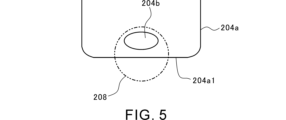
- FIG. 5 is a side view of the second auxiliary chamber housing.
- FIG. 6 is a diagram showing an example in which the positional relationship between the injection hole and the second communication hole is different from the examples in FIGS. 3 to 5.
- FIG. 7 is a diagram showing an example in which the positional relationship between the injection hole and the second communication hole is different from the examples in FIGS. 3 to 5.
- FIG. FIG. FIG. 1 is a diagram showing a schematic configuration of a gas engine according to an embodiment of the present disclosure.
- FIG. 2 is a diagram showing a schematic configuration of an ignition mechanism according to an embodiment of the present disclosure.
- FIG. 8 is a diagram showing an example in which the positional relationship between the injection hole and the second communication hole is different from the examples in FIGS. 3 to 5.
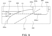
- FIG. 9 is a diagram showing an example in which a check valve is added to the example of FIGS.
- FIG. 10 is a diagram showing an example in which the shape of the injection hole is different from the examples in FIGS.
- FIG. 11 is a diagram showing an example in which the shape of the injection hole is different from the examples in FIGS.
- FIG. 12 is a diagram showing a schematic configuration of an ignition mechanism according to a modified example.
- FIG. 13 is an extracted diagram of the portion enclosed by the dashed dotted line in FIG.
- FIG. 1 is a diagram showing the general configuration of a gas engine 100. As shown in FIG. 1, the gas engine 100 includes a cylinder block 102, a cylinder head 104, and a piston 106.
- a cylinder 102a is formed in the cylinder block 102.
- the inner circumferential surface of the cylinder 102a may be formed by a cylinder liner that is pressed or cast into the interior of the cylinder block 102.
- a piston 106 is housed in the cylinder 102a.
- a combustion chamber 108 is formed inside the cylinder 102a. The combustion chamber 108 is defined by the cylinder 102a of the cylinder block 102, the cylinder head 104, and the crown surface 106a of the piston 106.
- the cylinder head 104 is formed with an intake port 104a and an exhaust port 104b.
- the intake port 104a and the exhaust port 104b open to the combustion chamber 108.
- the opening of the intake port 104a on the combustion chamber 108 side is opened and closed by an intake valve 110a.
- the opening of the exhaust port 104b on the combustion chamber 108 side is opened and closed by an exhaust valve 110b.
- An ignition mechanism 200 is provided in the cylinder head 104.
- the ignition mechanism 200 is disposed, for example, on the central axis of the piston 106.
- the ignition mechanism 200 includes a first sub-chamber 202, a second sub-chamber 204, and an ignition device 206. Details of the ignition mechanism 200 will be described later with reference to FIG. 2 etc.
- the gas engine 100 is, for example, a four-stroke engine.
- the intake stroke the intake valve 110a opens, the exhaust valve 110b closes, and the piston 106 moves toward bottom dead center.
- a mixture of fuel gas and air flows into the combustion chamber 108 from the intake port 104a.
- the intake valve 110a and the exhaust valve 110b close, and the piston 106 moves toward top dead center.
- the mixture compressed by the piston 106 is guided from the combustion chamber 108 through the first sub-chamber 202 to the second sub-chamber 204.
- the mixture is ignited by the ignition device 206, and a flame is ejected into the combustion chamber 108 through the second sub-chamber 204 and the first sub-chamber 202.
- the mixture is burned by the flame in the combustion chamber 108.
- the piston 106 is pressed toward the bottom dead center.
- the intake valve 110a closes, the exhaust valve 110b opens, and the piston 106 moves toward top dead center.
- the exhaust gas after combustion is exhausted from the combustion chamber 108 through the exhaust port 104b.
- the fuel gas used in the gas engine 100 is not particularly limited. However, in the gas engine 100, a flame-retardant fuel may be used. Examples of flame-retardant fuel include ammonia and dilute natural gas. When a flame-retardant fuel is used, if the promotion of combustion in the combustion chamber 108 is insufficient, the cylinder pressure may become low. In this embodiment, the ignition mechanism 200 is modified to promote combustion in the combustion chamber 108. Details of the ignition mechanism 200 are described below.
- the axial, circumferential, and radial directions of the piston 106 will also be referred to simply as the axial, circumferential, and radial directions, respectively.
- the top dead center side of the piston 106 will also be referred to as the upper side
- the bottom dead center side of the piston 106 will also be referred to as the lower side.
- FIG. 2 is a diagram showing the general configuration of ignition mechanism 200.
- the example in FIG. 2 is merely one example of ignition mechanism 200.
- the shape and arrangement of each component of ignition mechanism 200 are not limited to the example in FIG. 2.
- the ignition mechanism 200 includes a first subchamber 202, a second subchamber 204, an ignition device 206, an injection hole 208, a supply passage 210, and a gas supply source 212.
- the first subchamber 202 is a space that communicates with the combustion chamber 108.
- the first subchamber 202 is partitioned by a first subchamber housing 202a.
- the first subchamber housing 202a includes an upper housing 202a1 and a lower housing 202a2.
- the upper housing 202a1 has a flattened shape formed by vertically squashing a spherical shape.
- the upper housing 202a1 is arranged coaxially with the central axis of the piston 106.
- the lower part of the upper housing 202a1 is connected to the upper part of the lower housing 202a2.
- the upper housing 202a1 is in communication with the lower housing 202a2.
- the lower housing 202a2 has a cylindrical shape.
- the lower housing 202a2 is arranged coaxially with the central axis of the piston 106.
- the lower part of the lower housing 202a2 protrudes into the combustion chamber 108.
- the bottom surface 202a3 of the lower housing 202a2 is located within the combustion chamber 108.
- the combustion chamber 108 and the first sub-chamber 202 are separated by the bottom surface 202a3 of the lower housing 202a2 and the side surfaces surrounding the bottom surface 202a3.
- the first auxiliary chamber 202 communicates with the combustion chamber 108 via a first communication hole 202b.
- a plurality of first communication holes 202b are provided in the first auxiliary chamber housing 202a.
- the plurality of first communication holes 202b are provided in the lower part of the first auxiliary chamber housing 202a.
- the plurality of first communication holes 202b are provided in a portion of the first auxiliary chamber housing 202a that faces the combustion chamber 108.
- the multiple first communication holes 202b are spaced apart in the circumferential direction.
- the multiple first communication holes 202b are evenly spaced apart in the circumferential direction.
- the number and arrangement of the first communication holes 202b are not limited.
- the number of first communication holes 202b may be single.
- the multiple first communication holes 202b may be unevenly spaced apart in the circumferential direction.
- the shape of the first communication hole 202b is, for example, circular.
- the shape of the first communication hole 202b is not limited.
- the shape of the first communication hole 202b may be elliptical or polygonal.
- the second subchamber 204 is a space that communicates with the first subchamber 202.
- the volume of the second subchamber 204 is smaller than the volume of the first subchamber 202.
- the second subchamber 204 is partitioned by a second subchamber housing 204a.
- the second subchamber housing 204a has a cylindrical shape.
- the second subchamber housing 204a is arranged coaxially with the central axis of the piston 106.
- the lower part of the second subchamber housing 204a protrudes into the first subchamber 202.
- the bottom surface 204a1 of the second subchamber housing 204a is located within the first subchamber 202.
- the first subchamber 202 and the second subchamber 204 are separated by the bottom surface 204a1 of the second subchamber housing 204a and the side surfaces surrounding the bottom surface 204a1.
- the second subchamber 204 communicates with the first subchamber 202 via the second communication hole 204b.
- a plurality of second communication holes 204b are provided in the second subchamber housing 204a.
- the plurality of second communication holes 204b are provided in the lower part of the second subchamber housing 204a.
- the plurality of second communication holes 204b are provided in a portion of the second subchamber housing 204a that faces the first subchamber 202.
- the second communication holes 204b are spaced apart in the circumferential direction.
- the second communication holes 204b are equally spaced apart in the circumferential direction.
- the number and arrangement of the second communication holes 204b are not limited.
- the number of second communication holes 204b may be a single number.
- the second communication holes 204b may be unequally spaced apart in the circumferential direction.
- the shape of the second communication hole 204b is, for example, a circular shape.
- the shape of the second communication hole 204b is not limited.
- the shape of the second communication hole 204b may be an ellipse or a polygon.
- the ignition device 206 is provided to ignite the mixture of fuel gas and air.
- the ignition device 206 is provided in the second auxiliary chamber 204.
- the ignition device 206 includes a center electrode 206a and a ground electrode 206b.
- the ignition method used by the ignition device 206 is a method using a spark.
- the ignition method used by the ignition device 206 is not limited and may be pilot ignition, laser ignition, or the like.
- the center electrode 206a has, for example, a rod shape.
- the center electrode 206a extends downward in a straight line from the upper part of the second subchamber 204.
- the tip of the center electrode 206a is located near the center of the second subchamber 204.
- the center electrode 206a is disposed coaxially with the central axis of the piston 106.
- the ground electrode 206b has, for example, an arc shape.
- the ground electrode 206b extends downward in a curved manner from the upper part of the second subchamber 204.
- a gap is formed between the tip of the ground electrode 206b and the tip of the center electrode 206a. This gap is also called a spark gap.
- the potential of the ground electrode 206b is held at earth potential.
- the ignition device 206 and the second sub-chamber housing 204a may be directly connected to each other and may be detachable as a unit. In this case, the ignition device 206 and the second sub-chamber housing 204a may be connected to each other, for example, by screw fastening. Alternatively, the ignition device 206 and the second sub-chamber housing 204a may not be directly connected to each other and may be detachable separately.
- a mixture of fuel gas and air is guided from the combustion chamber 108 to the first auxiliary chamber 202 through the first communication hole 202b.
- the mixture guided to the first auxiliary chamber 202 is guided from the first auxiliary chamber 202 to the second auxiliary chamber 204 through the second communication hole 204b.
- the mixture in the second auxiliary chamber 204 is then ignited by the ignition device 206.
- a flame is ejected from the second auxiliary chamber 204 through the second communication hole 204b into the first auxiliary chamber 202.
- the mixture in the first auxiliary chamber 202 is ignited by the flame ejected into the first auxiliary chamber 202.
- a flame is ejected from the first auxiliary chamber 202 through the first communication hole 202b into the combustion chamber 108.
- the flame ejected into the combustion chamber 108 ignites the mixture in the combustion chamber 108.
- the ignition mechanism 200 includes, in addition to the first sub-chamber 202, the second sub-chamber 204, which has a volume smaller than the volume of the first sub-chamber 202.
- the mixture in the second sub-chamber 204 is ignited by the ignition device 206. Therefore, compared to directly igniting the mixture in the first sub-chamber 202, the combustion of the mixture in the second sub-chamber 204 can be completed earlier, and the timing of flame generation can be advanced. This speeds up the combustion in the first sub-chamber 202, and ultimately promotes the combustion in the combustion chamber 108.
- the injection hole 208 is a hole that injects gas into the second sub-chamber 204.
- the injection hole 208 is provided in the first sub-chamber 202.
- the injection hole 208 opens to the upper housing 202a1 of the first sub-chamber housing 202a.
- the injection hole 208 may open to a part of the first sub-chamber housing 202a other than the upper housing 202a1 (e.g., the lower housing 202a2).
- the shape of the injection hole 208 is, for example, circular.
- the shape of the injection hole 208 is not limited.
- the shape of the injection hole 208 may be elliptical or polygonal.
- the injection hole 208 is connected to a gas supply source 212 via a supply passage 210. As shown by the dashed arrow in FIG. 2, gas supplied from the supply source 212 is sent to the injection hole 208 through the supply passage 210. The gas sent to the injection hole 208 is then injected from the injection hole 208 into the first sub-chamber 202 and guided to the second sub-chamber 204 through the second communication hole 204b. The injection of gas from the injection hole 208 into the second sub-chamber 204 is performed, for example, at a timing before ignition by the ignition device 206. By supplying gas from the injection hole 208 to the second sub-chamber 204, the state of the second sub-chamber 204 can be adjusted, and the ignition of the mixture in the second sub-chamber 204 can be stabilized and accelerated.
- the gas injected by the injection hole 208 may be, for example, fuel gas, air, or a mixture of fuel gas and air.
- the gas injected by the injection hole 208 may be switchable between multiple types of gas.
- the injection hole 208 may be capable of switching between injecting fuel gas, air, and a mixture of fuel gas and air.
- the fuel concentration in the second sub-chamber 204 can be adjusted to be higher. This stabilizes and speeds up the ignition of the mixture in the second sub-chamber 204. Because the volume of the second sub-chamber 204 is smaller than the volume of the first sub-chamber 202, the time required to adjust the fuel concentration can be shortened, and the amount of fuel gas required to adjust the fuel concentration can be reduced.
- the temperature of the second sub-chamber 204 can be adjusted to be higher. This stabilizes and speeds up the ignition of the mixture in the second sub-chamber 204. Because the volume of the second sub-chamber 204 is smaller than the volume of the first sub-chamber 202, the time required to adjust the temperature can be shortened, and the amount of air supplied to adjust the temperature can be reduced.
- FIG. 3 is an extracted view of the dashed line portion of FIG. 2.
- FIG. 4 is a view of the second auxiliary chamber housing 204a from below.
- FIG. 4 is a view of the second auxiliary chamber housing 204a as viewed in the direction of arrow A1 in FIG. 3.
- FIG. 5 is a view of the second auxiliary chamber housing 204a as viewed from the side.
- FIG. 5 is a view of the second auxiliary chamber housing 204a as viewed in the direction of arrow A2 in FIG. 3.
- the shape of the injection hole 208 and the shape of the second communication hole 204b are circular.
- Figure 3 shows the central axis C1 of the injection hole 208 and the central axis C2 of the second communication hole 204b.
- the central axis C1 of the injection hole 208 is an axis along the direction in which gas is injected from the injection hole 208.
- the central axis C2 of the second communication hole 204b is an axis along the direction in which flame is injected from the second communication hole 204b.
- the central axis C1 of the injection hole 208 extends in the radial direction of the second sub-chamber housing 204a.
- the central axis C2 of the second communication hole 204b extends in the radial direction of the second sub-chamber housing 204a when viewed from below.
- the central axis C2 of the second communication hole 204b extends in a direction that inclines downward as it moves radially outward of the second sub-chamber housing 204a. Therefore, the direction of the central axis C1 of the injection hole 208 intersects with the direction of the central axis C2 of the second communication hole 204b.
- the direction of the central axis C1 of the injection hole 208 is parallel to the direction of the central axis C2 of the second communication hole 204b.
- the second sub-chamber housing 204a has four second communication holes 204b arranged at equal intervals in the circumferential direction. As shown in FIG. 5, when viewed in the direction of the central axis C1 of the injection hole 208, one second communication hole 204b is present within the projection area of the injection hole 208. In this way, the injection hole 208 faces one of the four second communication holes 204b. Therefore, the gas injected from the injection hole 208 is smoothly guided to the second sub-chamber 204 through the second communication hole 204b that the injection hole 208 faces.
- the entire area of one second communication hole 204b exists within the projection area of the injection hole 208.
- the injection hole 208 faces the second communication hole 204b.
- multiple second communication holes 204b may exist within the projection area of the injection hole 208. In this case, the injection hole 208 faces multiple second communication holes 204b.
- the ignition mechanism 200 includes the combustion chamber 108, the first sub-chamber 202 communicating with the combustion chamber 108 via the first communication hole 202b, the second sub-chamber 204 communicating with the first sub-chamber 202 via the second communication hole 204b and having a volume smaller than that of the first sub-chamber 202, and the ignition device 206 provided in the second sub-chamber 204.
- the combustion of the mixture in the second sub-chamber 204 can be completed earlier and the timing of the flame generation can be advanced. Therefore, the combustion in the first sub-chamber 202 can be accelerated, and the combustion in the combustion chamber 108 can be promoted.
- the ignition mechanism 200 includes an injection hole 208 that injects gas into the second sub-chamber 204.
- the state of the second sub-chamber 204 can be adjusted, and the ignition of the mixture in the second sub-chamber 204 can be stabilized and accelerated.
- the ignition mechanism 200 according to this embodiment can promote combustion in the combustion chamber 108.
- the injection hole 208 is provided in the first subchamber 202 and faces the second communication hole 204b. This allows the gas injected from the injection hole 208 to be smoothly guided to the second subchamber 204 through the second communication hole 204b to which the injection hole 208 faces. Therefore, the injection hole 208 can appropriately inject gas into the second subchamber 204.
- the injection hole 208 may be provided in the second subchamber 204.
- the volume of the first subchamber 202 is larger than the volume of the second subchamber 204, when the injection hole 208 is provided in the first subchamber 202, the freedom of installation of the injection hole 208 and the supply passage 210 is higher than when the injection hole 208 is provided in the second subchamber 204.
- the direction of the central axis C1 of the injection hole 208 intersects with the direction of the central axis C2 of the second communication hole 204b. If the direction of the central axis C1 is parallel to the direction of the central axis C2 of the second communication hole 204b, the flame ejected from the second sub-chamber 204 through the second communication hole 204b into the first sub-chamber 202 advances toward the injection hole 208, and is therefore unlikely to contribute to the ignition of the mixture in the first sub-chamber 202.
- the ignition of the mixture in the first sub-chamber 202 by the flame ejected from the second sub-chamber 204 through the second communication hole 204b into the first sub-chamber 202 can be promoted.
- the direction of the central axis C1 may be parallel to the direction of the central axis C2 of the second communication hole 204b.
- FIGS. 6 to 8 are diagrams showing examples in which the positional relationship between the injection hole 208 and the second communication hole 204b is different from that of the examples of FIGS. 3 to 5.
- the direction of the central axis C1 of the injection hole 208 intersects with the direction of the central axis C2 of the second communication hole 204b. Therefore, in each of the examples of FIGS. 6 to 8, ignition of the mixture in the first sub-chamber 202 by the flame ejected from the second sub-chamber 204 through the second communication hole 204b into the first sub-chamber 202 can be promoted.
- FIG. 6 is a diagram showing a portion corresponding to FIG. 3.
- the central axis C2 of the second communication hole 204b extends in the radial direction of the second sub-chamber housing 204a.
- the central axis C1 of the injection hole 208 extends in a direction that inclines downward as it advances radially inward of the second sub-chamber housing 204a.
- Figures 7 and 8 are views of the injection hole 208 and the second auxiliary housing 204a as viewed from below.
- the direction of the central axis C1 of the injection hole 208 is parallel to the direction of the central axis C2 of the second communication hole 204b.
- the direction of the central axis C1 of the injection hole 208 intersects with the direction of the central axis C2 of the second communication hole 204b.
- the central axis C1 of the injection hole 208 extends in a direction inclined relative to the radial direction of the second sub-chamber housing 204a, and the central axis C2 of the second communication hole 204b extends in the radial direction of the second sub-chamber housing 204a.
- the central axis C1 of the injection hole 208 extends in a direction inclined relative to the radial direction of the second sub-chamber housing 204a
- the central axis C2 of the second communication hole 204b extends in a direction inclined relative to the radial direction of the second sub-chamber housing 204a.
- FIG. 9 is a diagram showing an example in which a check valve 214 is added to the examples of FIGS. 3 to 5.
- a check valve 214 is provided in the supply flow passage 210.
- the check valve 214 restricts the flow of gas in a direction from the supply source 212 toward the injection hole 208.
- the check valve 214 allows the flow of gas in the supply flow passage 210 from the supply source 212 toward the injection hole 208, while prohibiting the flow of gas in the direction from the injection hole 208 toward the supply source 212.
- the check valve 214 is provided in the supply flow passage 210, and when combustion is taking place in the first sub-chamber 202, it is possible to prevent a flame from progressing from the first sub-chamber 202 through the injection hole 208 into the supply flow passage 210.
- the injection hole 208 is an elongated hole extending in a direction perpendicular to the up-down direction.
- the injection hole 208 is shaped as an elongated hole, which increases the reliability of the injection hole 208 facing the second communication hole 204b.
- the length of the injection hole 208 in the extension direction (length in the left-right direction in FIG. 10) is approximately the same as the diameter of the second sub-chamber housing 204a. Therefore, regardless of the position of the second sub-chamber housing 204a in the rotation direction, the injection hole 208 can face at least two second communication holes 204b.
- the length of the injection hole 208 in the extension direction (length in the left-right direction in FIG. 11) is approximately the same as the diameter of the second sub-chamber housing 204a minus the diameter of the second communication hole 204b. Therefore, regardless of the position of the second sub-chamber housing 204a in the rotation direction, the injection hole 208 can face at least one second communication hole 204b.
- FIG. 12 is a diagram showing the general configuration of a modified ignition mechanism 200A.
- the installation position of the injection hole 208 is different from that of the ignition mechanism 200 described above.
- the injection hole 208 is provided in the second subchamber 204.
- the injection hole 208 opens to the side surface of the second subchamber housing 204a of the second subchamber 204.
- the injection hole 208 may open to a part of the second subchamber housing 204a other than the side surface.
- the injection hole 208 faces into the second subchamber 204.
- the gas supplied from the supply source 212 is sent to the injection hole 208 through the supply passage 210.
- the gas sent to the injection hole 208 is then directly injected from the injection hole 208 into the second sub-chamber 204.
- the injection of gas from the injection hole 208 into the second sub-chamber 204 is performed, for example, at a timing before ignition by the ignition device 206.
- the gas injected from the injection hole 208 can be, for example, fuel gas, air, or a mixture of fuel gas and air.
- the ignition mechanism 200A includes a combustion chamber 108, a first sub-chamber 202 that communicates with the combustion chamber 108 via a first communication hole 202b, a second sub-chamber 204 that communicates with the first sub-chamber 202 via a second communication hole 204b and has a volume smaller than that of the first sub-chamber 202, an ignition device 206 provided in the second sub-chamber 204, and an injection hole 208 that injects gas into the second sub-chamber 204.
- This can promote combustion in the combustion chamber 108, like the ignition mechanism 200 described above.
- the injection hole 208 is provided in the second sub-chamber 204. This allows gas to be directly injected from the injection hole 208 into the second sub-chamber 204. Therefore, the reliability of supplying gas to the second sub-chamber 204 can be increased compared to when the injection hole 208 is provided in the first sub-chamber 202.
- FIG. 13 is an extracted view of the dashed line portion of FIG. 12.
- the supply flow passage 210 is provided with a check valve 214, similar to the example of FIG. 9.
- the check valve 214 restricts the flow of gas in a direction from the supply source 212 toward the injection hole 208, similar to the example of FIG. 9.
- the check valve 214 may be omitted from the example of FIG. 13.
- One or more additional subchambers may be interposed between the first subchamber 202 and the second subchamber 204.
- a third subchamber may be interposed between the first subchamber 202 and the second subchamber 204.
- the first subchamber 202 and the third subchamber communicate with each other via a communication hole
- the third subchamber and the second subchamber 204 communicate with each other via another communication hole different from the above communication hole.
- the first subchamber 202 and the second subchamber 204 communicate with each other via the third subchamber.
- the shape of the first sub-chamber housing 202a and the shape of the second sub-chamber housing 204a are not limited to the example of FIG. 2 or the example of FIG. 12.
- the upper housing 202a1 may be omitted from the example of FIG. 2 or the example of FIG. 12, and the first sub-chamber housing 202a may have a cylindrical shape as a whole.
- the shape of the second sub-chamber housing 204a may be a shape other than a cylindrical shape.
- each component is not limited to the example of FIG. 2 or the example of FIG. 12.
- the first subchamber housing 202a, the second subchamber housing 204a, and the ignition device 206 do not have to be arranged coaxially with the central axis of the piston 106.
- the first subchamber housing 202a and the second subchamber housing 204a do not have to be arranged coaxially with each other.
- the second subchamber housing 204a and the ignition device 206 do not have to be arranged coaxially with each other.
- the disclosure helps promote combustion in combustion chambers, which can contribute, for example, to Sustainable Development Goal (SDG) Goal 7 "Ensure access to affordable, reliable, sustainable and modern energy” and Goal 13 "Take urgent action to combat climate change and its impacts.”
- SDG Sustainable Development Goal
- Gas engine 108 Combustion chamber 202: First auxiliary chamber 202b: First communication hole 204: Second auxiliary chamber 204b: Second communication hole 206: Ignition device 208: Injection hole 210: Supply passage 212: Supply source 214: Check valve C1: Central axis C2: Central axis
Landscapes
- Engineering & Computer Science (AREA)
- Chemical & Material Sciences (AREA)
- Combustion & Propulsion (AREA)
- Mechanical Engineering (AREA)
- General Engineering & Computer Science (AREA)
- Chemical Kinetics & Catalysis (AREA)
- General Chemical & Material Sciences (AREA)
- Oil, Petroleum & Natural Gas (AREA)
- Combustion Methods Of Internal-Combustion Engines (AREA)
Priority Applications (5)
| Application Number | Priority Date | Filing Date | Title |
|---|---|---|---|
| JP2025516565A JPWO2024224808A1 (https=) | 2023-04-27 | 2024-03-04 | |
| CN202480019854.6A CN120898063A (zh) | 2023-04-27 | 2024-03-04 | 燃气发动机 |
| KR1020257034042A KR20250168316A (ko) | 2023-04-27 | 2024-03-04 | 가스 엔진 |
| EP24796566.8A EP4703573A1 (en) | 2023-04-27 | 2024-03-04 | Gas engine |
| US19/331,031 US20260015965A1 (en) | 2023-04-27 | 2025-09-17 | Gas engine |
Applications Claiming Priority (2)
| Application Number | Priority Date | Filing Date | Title |
|---|---|---|---|
| JP2023073394 | 2023-04-27 | ||
| JP2023-073394 | 2023-04-27 |
Related Child Applications (1)
| Application Number | Title | Priority Date | Filing Date |
|---|---|---|---|
| US19/331,031 Continuation US20260015965A1 (en) | 2023-04-27 | 2025-09-17 | Gas engine |
Publications (1)
| Publication Number | Publication Date |
|---|---|
| WO2024224808A1 true WO2024224808A1 (ja) | 2024-10-31 |
Family
ID=93255950
Family Applications (1)
| Application Number | Title | Priority Date | Filing Date |
|---|---|---|---|
| PCT/JP2024/008028 Ceased WO2024224808A1 (ja) | 2023-04-27 | 2024-03-04 | ガスエンジン |
Country Status (6)
| Country | Link |
|---|---|
| US (1) | US20260015965A1 (https=) |
| EP (1) | EP4703573A1 (https=) |
| JP (1) | JPWO2024224808A1 (https=) |
| KR (1) | KR20250168316A (https=) |
| CN (1) | CN120898063A (https=) |
| WO (1) | WO2024224808A1 (https=) |
Citations (8)
| Publication number | Priority date | Publication date | Assignee | Title |
|---|---|---|---|---|
| JP2004204835A (ja) * | 2002-10-28 | 2004-07-22 | Toyota Motor Corp | 火花点火式内燃機関 |
| JP2009257320A (ja) * | 2008-04-11 | 2009-11-05 | Man Diesel Se | エンジン |
| JP2009299593A (ja) * | 2008-06-13 | 2009-12-24 | Osaka Gas Co Ltd | エンジン |
| JP2010242739A (ja) * | 2009-04-04 | 2010-10-28 | Man Diesel Se | ガスエンジンのための点火システム、当該点火システムを備えるガスエンジンおよび当該ガスエンジンを駆動する方法 |
| JP2015530514A (ja) * | 2012-09-06 | 2015-10-15 | プロメテウス アプライド テクノロジーズ,エルエルシー | 大口径ガスエンジン用2段式予燃焼室 |
| JP2020148198A (ja) | 2019-03-08 | 2020-09-17 | Jfeエンジニアリング株式会社 | ディーゼルエンジン |
| JP7226639B2 (ja) * | 2020-02-10 | 2023-02-21 | 三菱自動車工業株式会社 | 副室式火花点火エンジン |
| JP2023073394A (ja) | 2020-01-31 | 2023-05-25 | 富士フイルム株式会社 | 磁気テープ、磁気テープカートリッジおよび磁気テープ装置 |
-
2024
- 2024-03-04 EP EP24796566.8A patent/EP4703573A1/en active Pending
- 2024-03-04 WO PCT/JP2024/008028 patent/WO2024224808A1/ja not_active Ceased
- 2024-03-04 CN CN202480019854.6A patent/CN120898063A/zh active Pending
- 2024-03-04 JP JP2025516565A patent/JPWO2024224808A1/ja active Pending
- 2024-03-04 KR KR1020257034042A patent/KR20250168316A/ko active Pending
-
2025
- 2025-09-17 US US19/331,031 patent/US20260015965A1/en active Pending
Patent Citations (8)
| Publication number | Priority date | Publication date | Assignee | Title |
|---|---|---|---|---|
| JP2004204835A (ja) * | 2002-10-28 | 2004-07-22 | Toyota Motor Corp | 火花点火式内燃機関 |
| JP2009257320A (ja) * | 2008-04-11 | 2009-11-05 | Man Diesel Se | エンジン |
| JP2009299593A (ja) * | 2008-06-13 | 2009-12-24 | Osaka Gas Co Ltd | エンジン |
| JP2010242739A (ja) * | 2009-04-04 | 2010-10-28 | Man Diesel Se | ガスエンジンのための点火システム、当該点火システムを備えるガスエンジンおよび当該ガスエンジンを駆動する方法 |
| JP2015530514A (ja) * | 2012-09-06 | 2015-10-15 | プロメテウス アプライド テクノロジーズ,エルエルシー | 大口径ガスエンジン用2段式予燃焼室 |
| JP2020148198A (ja) | 2019-03-08 | 2020-09-17 | Jfeエンジニアリング株式会社 | ディーゼルエンジン |
| JP2023073394A (ja) | 2020-01-31 | 2023-05-25 | 富士フイルム株式会社 | 磁気テープ、磁気テープカートリッジおよび磁気テープ装置 |
| JP7226639B2 (ja) * | 2020-02-10 | 2023-02-21 | 三菱自動車工業株式会社 | 副室式火花点火エンジン |
Non-Patent Citations (1)
| Title |
|---|
| See also references of EP4703573A1 |
Also Published As
| Publication number | Publication date |
|---|---|
| JPWO2024224808A1 (https=) | 2024-10-31 |
| US20260015965A1 (en) | 2026-01-15 |
| KR20250168316A (ko) | 2025-12-02 |
| CN120898063A (zh) | 2025-11-04 |
| EP4703573A1 (en) | 2026-03-04 |
Similar Documents
| Publication | Publication Date | Title |
|---|---|---|
| US10968814B2 (en) | Internal combustion engine for a motor vehicle | |
| KR102156098B1 (ko) | 내연기관의 예연소실 및 그 작동 방법 | |
| EP3012444B1 (en) | Pre-combustion chamber assembly for internal combustion engines | |
| JP4380691B2 (ja) | 副室式内燃機関 | |
| JP5765819B2 (ja) | 2サイクルガスエンジン | |
| EP3118433B1 (en) | Pre-combustion chamber assembly for internal combustion engines | |
| JP5192177B2 (ja) | 副室式エンジン | |
| JP2009221936A (ja) | 副室式エンジン | |
| JP2010144516A (ja) | ガスエンジンの予燃焼器 | |
| WO2024224808A1 (ja) | ガスエンジン | |
| WO2015093309A1 (ja) | ガスエンジン | |
| US4043309A (en) | Internal combustion engine having auxiliary combustion chamber | |
| JP2020159238A (ja) | デュアルフューエルエンジン | |
| CN116927939A (zh) | 预燃烧室系统、点火装置及发动机 | |
| CN100400816C (zh) | 燃料直喷式内燃机 | |
| JP7260331B2 (ja) | 副燃焼室付き内燃機関 | |
| JP7000045B2 (ja) | ガスエンジン | |
| WO2026070723A1 (ja) | 点火システム | |
| US11994058B2 (en) | Ignition charge formation stabilization in gaseous fuel engine system | |
| JP5085419B2 (ja) | エンジン及びエンジン用点火プラグ | |
| JP2016006325A (ja) | 2サイクルガスエンジン及び2サイクルガスエンジン用の燃料ガス噴射システム | |
| JP2015021391A (ja) | 内燃機関 | |
| JP7643293B2 (ja) | 内燃機関用のスパークプラグ及びこれを備えた内燃機関 | |
| WO2026070311A1 (ja) | 点火システム | |
| JP7740516B2 (ja) | エンジン |
Legal Events
| Date | Code | Title | Description |
|---|---|---|---|
| 121 | Ep: the epo has been informed by wipo that ep was designated in this application |
Ref document number: 24796566 Country of ref document: EP Kind code of ref document: A1 |
|
| ENP | Entry into the national phase |
Ref document number: 2025516565 Country of ref document: JP Kind code of ref document: A |
|
| WWE | Wipo information: entry into national phase |
Ref document number: 2025516565 Country of ref document: JP |
|
| WWE | Wipo information: entry into national phase |
Ref document number: 202480019854.6 Country of ref document: CN |
|
| ENP | Entry into the national phase |
Ref document number: 1020257034042 Country of ref document: KR Free format text: ST27 STATUS EVENT CODE: A-0-1-A10-A15-NAP-PA0105 (AS PROVIDED BY THE NATIONAL OFFICE) |
|
| WWE | Wipo information: entry into national phase |
Ref document number: KR1020257034042 Country of ref document: KR Ref document number: 1020257034042 Country of ref document: KR |
|
| WWP | Wipo information: published in national office |
Ref document number: 202480019854.6 Country of ref document: CN |
|
| WWE | Wipo information: entry into national phase |
Ref document number: 2024796566 Country of ref document: EP |
|
| NENP | Non-entry into the national phase |
Ref country code: DE |
|
| ENP | Entry into the national phase |
Ref document number: 2024796566 Country of ref document: EP Effective date: 20251127 |
|
| WWP | Wipo information: published in national office |
Ref document number: 1020257034042 Country of ref document: KR |
|
| ENP | Entry into the national phase |
Ref document number: 2024796566 Country of ref document: EP Effective date: 20251127 |
|
| ENP | Entry into the national phase |
Ref document number: 2024796566 Country of ref document: EP Effective date: 20251127 |
|
| ENP | Entry into the national phase |
Ref document number: 2024796566 Country of ref document: EP Effective date: 20251127 |
|
| ENP | Entry into the national phase |
Ref document number: 2024796566 Country of ref document: EP Effective date: 20251127 |
|
| ENP | Entry into the national phase |
Ref document number: 2024796566 Country of ref document: EP Effective date: 20251127 |
|
| ENP | Entry into the national phase |
Ref document number: 2024796566 Country of ref document: EP Effective date: 20251127 |
|
| ENP | Entry into the national phase |
Ref document number: 2024796566 Country of ref document: EP Effective date: 20251127 |
|
| ENP | Entry into the national phase |
Ref document number: 2024796566 Country of ref document: EP Effective date: 20251127 |
|
| WWP | Wipo information: published in national office |
Ref document number: 2024796566 Country of ref document: EP |