EP3118433B1 - Pre-combustion chamber assembly for internal combustion engines - Google Patents
Pre-combustion chamber assembly for internal combustion engines Download PDFInfo
- Publication number
- EP3118433B1 EP3118433B1 EP15176983.3A EP15176983A EP3118433B1 EP 3118433 B1 EP3118433 B1 EP 3118433B1 EP 15176983 A EP15176983 A EP 15176983A EP 3118433 B1 EP3118433 B1 EP 3118433B1
- Authority
- EP
- European Patent Office
- Prior art keywords
- combustion chamber
- central axis
- main portion
- main
- combustion
- Prior art date
- Legal status (The legal status is an assumption and is not a legal conclusion. Google has not performed a legal analysis and makes no representation as to the accuracy of the status listed.)
- Active
Links
- 238000002485 combustion reaction Methods 0.000 title claims description 259
- 239000000446 fuel Substances 0.000 claims description 84
- 230000004308 accommodation Effects 0.000 claims description 34
- 239000000203 mixture Substances 0.000 claims description 19
- 238000000034 method Methods 0.000 claims description 11
- 230000006835 compression Effects 0.000 claims description 5
- 238000007906 compression Methods 0.000 claims description 5
- 230000000712 assembly Effects 0.000 description 4
- 238000000429 assembly Methods 0.000 description 4
- 239000007789 gas Substances 0.000 description 4
- 230000000694 effects Effects 0.000 description 3
- 238000003466 welding Methods 0.000 description 3
- ATUOYWHBWRKTHZ-UHFFFAOYSA-N Propane Chemical compound CCC ATUOYWHBWRKTHZ-UHFFFAOYSA-N 0.000 description 2
- 238000004891 communication Methods 0.000 description 2
- 239000012530 fluid Substances 0.000 description 2
- VNWKTOKETHGBQD-UHFFFAOYSA-N methane Chemical compound C VNWKTOKETHGBQD-UHFFFAOYSA-N 0.000 description 2
- 238000007789 sealing Methods 0.000 description 2
- 238000005476 soldering Methods 0.000 description 2
- 238000001816 cooling Methods 0.000 description 1
- 239000012809 cooling fluid Substances 0.000 description 1
- -1 diesel Substances 0.000 description 1
- 238000006073 displacement reaction Methods 0.000 description 1
- 230000000977 initiatory effect Effects 0.000 description 1
- 238000009434 installation Methods 0.000 description 1
- 230000003137 locomotive effect Effects 0.000 description 1
- 239000000463 material Substances 0.000 description 1
- 239000002184 metal Substances 0.000 description 1
- 238000000465 moulding Methods 0.000 description 1
- 239000003345 natural gas Substances 0.000 description 1
- 230000010355 oscillation Effects 0.000 description 1
- 239000001294 propane Substances 0.000 description 1
- 238000000926 separation method Methods 0.000 description 1
- 238000005245 sintering Methods 0.000 description 1
- 239000011343 solid material Substances 0.000 description 1
- 230000000087 stabilizing effect Effects 0.000 description 1
Images

Classifications
-
- F—MECHANICAL ENGINEERING; LIGHTING; HEATING; WEAPONS; BLASTING
- F02—COMBUSTION ENGINES; HOT-GAS OR COMBUSTION-PRODUCT ENGINE PLANTS
- F02M—SUPPLYING COMBUSTION ENGINES IN GENERAL WITH COMBUSTIBLE MIXTURES OR CONSTITUENTS THEREOF
- F02M21/00—Apparatus for supplying engines with non-liquid fuels, e.g. gaseous fuels stored in liquid form
- F02M21/02—Apparatus for supplying engines with non-liquid fuels, e.g. gaseous fuels stored in liquid form for gaseous fuels
- F02M21/0218—Details on the gaseous fuel supply system, e.g. tanks, valves, pipes, pumps, rails, injectors or mixers
- F02M21/0248—Injectors
- F02M21/0275—Injectors for in-cylinder direct injection, e.g. injector combined with spark plug
-
- F—MECHANICAL ENGINEERING; LIGHTING; HEATING; WEAPONS; BLASTING
- F02—COMBUSTION ENGINES; HOT-GAS OR COMBUSTION-PRODUCT ENGINE PLANTS
- F02B—INTERNAL-COMBUSTION PISTON ENGINES; COMBUSTION ENGINES IN GENERAL
- F02B19/00—Engines characterised by precombustion chambers
- F02B19/10—Engines characterised by precombustion chambers with fuel introduced partly into pre-combustion chamber, and partly into cylinder
- F02B19/1004—Engines characterised by precombustion chambers with fuel introduced partly into pre-combustion chamber, and partly into cylinder details of combustion chamber, e.g. mounting arrangements
- F02B19/1014—Engines characterised by precombustion chambers with fuel introduced partly into pre-combustion chamber, and partly into cylinder details of combustion chamber, e.g. mounting arrangements design parameters, e.g. volume, torch passage cross sectional area, length, orientation, or the like
-
- F—MECHANICAL ENGINEERING; LIGHTING; HEATING; WEAPONS; BLASTING
- F02—COMBUSTION ENGINES; HOT-GAS OR COMBUSTION-PRODUCT ENGINE PLANTS
- F02B—INTERNAL-COMBUSTION PISTON ENGINES; COMBUSTION ENGINES IN GENERAL
- F02B19/00—Engines characterised by precombustion chambers
- F02B19/12—Engines characterised by precombustion chambers with positive ignition
-
- F—MECHANICAL ENGINEERING; LIGHTING; HEATING; WEAPONS; BLASTING
- F02—COMBUSTION ENGINES; HOT-GAS OR COMBUSTION-PRODUCT ENGINE PLANTS
- F02M—SUPPLYING COMBUSTION ENGINES IN GENERAL WITH COMBUSTIBLE MIXTURES OR CONSTITUENTS THEREOF
- F02M21/00—Apparatus for supplying engines with non-liquid fuels, e.g. gaseous fuels stored in liquid form
- F02M21/02—Apparatus for supplying engines with non-liquid fuels, e.g. gaseous fuels stored in liquid form for gaseous fuels
- F02M21/0218—Details on the gaseous fuel supply system, e.g. tanks, valves, pipes, pumps, rails, injectors or mixers
- F02M21/0248—Injectors
- F02M21/0281—Adapters, sockets or the like to mount injection valves onto engines; Fuel guiding passages between injectors and the air intake system or the combustion chamber
-
- F—MECHANICAL ENGINEERING; LIGHTING; HEATING; WEAPONS; BLASTING
- F02—COMBUSTION ENGINES; HOT-GAS OR COMBUSTION-PRODUCT ENGINE PLANTS
- F02P—IGNITION, OTHER THAN COMPRESSION IGNITION, FOR INTERNAL-COMBUSTION ENGINES; TESTING OF IGNITION TIMING IN COMPRESSION-IGNITION ENGINES
- F02P13/00—Sparking plugs structurally combined with other parts of internal-combustion engines
Definitions
- the present disclosure generally relates to a pre-combustion chamber assembly for internal combustion engines.
- the present disclosure relates further to an internal combustion engine and a pre-combustion chamber section.
- the present disclosure relates further to a method for operating an internal combustion engine operating at least partly on gaseous fuel.
- a pre-combustion chamber assembly including a pre-combustion chamber may have a spark plug partially protruding into the pre-combustion chamber.
- Such a pre-combustion chamber assembly may further include a fuel supply for supplying some amount of fuel into the pre-combustion chamber.
- the flames may advance through orifices provided in the pre-combustion chamber into the main combustion chamber, where the flames may ignite the main amount of fuel and air for operating the internal combustion engine.
- a fuel nozzle includes at least one port for receiving fuel, a sidewall forming ports for introducing fuel into a pre-combustion chamber, and a plurality of conduits formed between the first end and the sidewall.
- US 7,451,727 B2 discloses an engine comprising a working cylinder provided with a piston, a pre-ignition chamber provided with a spark plug, and a combustion chamber which are connected to a compressor cylinder by channels.
- the compressor cylinder is provided with fuel and air supplying channels arranged in the top section thereof and with a piston and shutoff valve.
- pre-combustion chamber assemblies are known from, for example, US 4,119,065 A , US 3,970,053 A , US 6,513,483 B2 , EP 0 338 882 B1 , AT 510 435 B1 , and WO 2009/109694 A2 .
- US 3,406,667 A discloses a stratified charge ignition system for a spark type internal combustion engine.
- the apparatus comprises a precombustion chamber coupled in fluid communication with each primary combustion chamber of the engine in place of the spark plug normally coupled thereto.
- Carburetion means supply a relatively rich fuel-air mixture to each precombustion chamber.
- a spark ignition means effects the ignition of the fuel air mixture supplied to each of said chambers in timed sequence to the operation of the engine.
- Fluid communication between each precombustion chamber and the primary combustion chamber coupled thereto is provided by an orifice comprising a Borda mouthpiece opening into the precombustion to define an imperforate lip extending thereinto.
- a nozzle of substantially truncated conical shape extends from the mouthpiece in diverging relationship relative thereto and opening into the primary combustion chamber.
- US 5 230 313 A refers to a cylinder head having a conventional spark plug therein, for engine start-up, and having a precombustion chamber unit mounted therein as well, for cleaner, more stable normal running of the engine.
- the method defines the reaming out of spark plug apertures in the head to accommodate the installation of the precombustion chamber unit.
- the assembly disclosed herein comprises a sleeve with a plurality of fluid-accommodating ports formed in a pre-combustion chamber, and these ports are arranged in parallel and radially aligned in the upper section. But only one orificial without a plurality of flow transfer passages has an outlet located in the flame nozzle in the lower section. An offset between a main portion having a main portion central axis and a longitudinal central axis of the pre-combustion chamber upper and lower sections is not mentioned.
- EP 2 700 796 A1 shows a pre-combustion chamber tip of an internal combustion engine exposed to high thermal and mechanical stress. It is disclosed to efficiently use an limited space by providing a first group of orifices extending at a first angle with respect to a center axis and a second group of orifices extending at a second angle with respect to the center axis , wherein the outlets of the orifices are arranged at a first axial position.
- the chamber disclosed herein is symmetrical.
- EP0377265 and WO2013096979 disclose pre-combustion chamber assemblies.
- the present disclosure is directed, at least in part, to improving or overcoming one or more aspects of prior systems.
- a pre-combustion chamber assembly for internal combustion engines operating at least partly on gaseous fuel and having a cylinder defining a main combustion chamber.
- the pre-combustion chamber assembly extends along a longitudinal central axis and comprises a pre-combustion chamber upper section extending along the longitudinal central axis and including an ignition device accommodation portion configured to accommodate an ignition device and a fuel supply accommodation portion for accommodating a fuel supply device, the fuel supply accommodation portion having a central axis extending in parallel to the longitudinal central axis with a predetermined offset.
- the precombustion chamber assembly further comprises a pre-combustion chamber lower section extending along the longitudinal central axis and connected to the pre-combustion chamber upper section.
- the pre-combustion chamber lower section includes a plurality of flow transfer passages.
- the pre-combustion chamber assembly further comprises a pre-combustion chamber delimited within the pre-combustion chamber upper section and the precombustion chamber lower section, and fluidly connectable to the main combustion chamber via the plurality of flow transfer passages.
- the precombustion chamber includes a main portion having a main portion central axis extending in parallel to the longitudinal central axis with a predetermined offset.
- the pre-combustion chamber assembly further comprises an ignition device mounted to the ignition device accommodation portion and configured to initiate a combustion event at an ignition point within the main portion. The ignition point lies substantially on the main portion central axis.
- an internal combustion engine operating at least partly on gaseous fuel comprises a cylinder defining a main combustion chamber, a cylinder head delimiting the main combustion chamber at a top end, and a pre-combustion chamber assembly according to the present disclosure.
- the pre-combustion chamber assembly is mounted to the cylinder head and configured to initiate a main combustion event within the main combustion chamber.
- a method for operating an internal combustion engine operating at least partly on gaseous fuel and that includes a main combustion chamber and a pre-combustion chamber assembly including a longitudinal central axis and a pre-combustion chamber with a main portion having a main portion central axis extending substantially in parallel to the longitudinal central axis with a predetermined offset is disclosed.
- the pre-combustion chamber is fluidly connected to the main combustion chamber via a plurality of flow transfer passages.
- the disclosed method comprises the steps of supplying a combustion mixture into the main portion via the plurality of flow transfer passages during a compression stroke of the internal combustion engine, and igniting the combustion mixture at an ignition point within the main portion.
- the ignition point lies on the main portion central axis.
- the disclosed method further may comprise the step of supplying a predetermined amount of gaseous fuel into the main portion for enriching the main portion with gaseous fuel by means of a fuel supply accommodation portion included in a pre-combustion chamber upper section of the pre-combustion chamber assembly and configured to accommodate a fuel supply device, the fuel supply accommodation portion having a central axis extending in parallel to the longitudinal central axis with a predetermined offset.
- a precombustion chamber lower section of a pre-combustion chamber assembly as disclosed herein includes a pre-combustion chamber lower section body extending along the longitudinal central axis and is configured to be mounted to the pre-combustion chamber upper section of the pre-combustion chamber assembly disclosed herein.
- a pre-combustion chamber tip connects to the precombustion chamber lower section body and includes a plurality of flow transfer passages, the pre-combustion chamber tip extending along the longitudinal central axis.
- a pre-combustion chamber has a main portion formed substantially within the connecting portion and a riser passage fluidly connected to the main portion and formed substantially within the pre-combustion chamber tip, the main portion having a main portion central axis extending in parallel to the longitudinal central axis with a predetermined offset, such that, in a circumferential direction about the longitudinal central axis, the pre-combustion chamber lower section includes a varying radial wall thickness.
- the present disclosure is based at least in part on the realization that asymmetrically arranging a pre-combustion chamber within a precombustion chamber assembly with respect to a longitudinally axis of the precombustion chamber assembly and providing a ignition point lying on a central axis of the pre-combustion chamber may support in stabilizing a combustion event within the pre-combustion chamber.
- the combustion event is provided symmetrically within the pre-combustion chamber and, hence, extinguishing of flames generated during the combustion event may be prevent due to a uniform distance of the ignition point to the inner walls of the combustion chamber.
- the distance between the ignition point and the inner walls of the combustion chamber is as great as possible for preventing the flames from being extinguished too early during the ignition event.
- a "central axis” describes an axis of symmetry of a respective element or portion. That is that an element or portion having a “central axis” is substantially symmetrical with respect to said axis. In particular, an element or portion having a “central axis” is rotationally symmetrical with respect to said axis.
- the internal combustion engine 10 may include features not shown, such as fuel systems, air systems, cooling systems, peripheries, drivetrain components, turbochargers, etc.
- the internal combustion engine 10 is considered as a four-stroke gaseous fuel internal combustion engine.
- the gaseous fuel internal combustion engine 10 may be any type of engine (two-stroke, turbine, gas, diesel, natural gas, propane, etc.) that would utilize a pre-combustion chamber.
- the internal combustion engine 10 may be of any size, with any number of cylinders, and in any configuration ("V", in-line, radial, etc.).
- the internal combustion engine 10 may be used to power any machine or other device, including locomotive applications, on-highway trucks or vehicles, off-highway trucks or machines, earth moving equipment, generators, aerospace applications, marine applications, pumps, stationary equipment, or other engine powered applications.
- the internal combustion engine 10 may include an engine block 12 having a plurality of cylinders 14 (one of which is illustrated in Fig. 1 ).
- a piston 16 may be slidably disposed within the cylinder (or cylinder liner) 14 to reciprocate between a top dead center position and a bottom dead center position.
- a connecting rod 18 may connect the piston 16 to an eccentric crankpin 20 of a crankshaft 22 such that reciprocating motion of the piston may result in rotation of the crankshaft 22.
- the internal combustion engine 10 may also include a cylinder head 24 engaged with the engine block 12 to cover the cylinder 14, thereby delimiting a main combustion chamber 26.
- the cylinder head 24 may define intake and exhaust openings 28 that may allow intake gases into the main combustion chamber 26 and exhaust gases out of the main combustion chamber 26, respectively.
- Engine valves 30 may be positioned to selectively open and close the openings 28.
- Each cylinder 14 may include multiple intake and exhaust openings 28.
- the internal combustion engine 10 may include a series of valve actuation assemblies 40 (one of which is illustrated in Fig. 1 ).
- the multiple valve actuation assemblies 40 may be provided per cylinder 14.
- one valve actuation assembly may be used to open and close the intake valves and another valve actuation assembly may be provided to open and close the exhaust valves.
- the valve actuation assembly 40 may include a rocker arm 46.
- the rocker arm 46 may be pivotally mounted in the cylinder head 24 and may attach to the engine valves 30 at one end and may attach to a push rod 48 at the other end. Oscillation of rocker arm 46 about its pivot point 50 may cause the valves 30 to move between an open position and a closed position.
- the valve actuation assembly 40 may also include valve springs 52 that may bias the valves 30 toward the closed position (i.e. closing the intake and exhaust openings 28).
- the other end of the push rod 48 may engage a lifter 54 which may engage a camshaft 56.
- the camshaft 56 may operatively engage the crankshaft 22.
- the camshaft 56 may be connected with crankshaft 22 in any manner readily apparent to one skilled in the art where rotation of the crankshaft 22 may result in rotation of the camshaft 56.
- camshaft 56 may be connected to crankshaft 22 through a gear train (not shown).
- a first cam lobe 58 may be disposed on the camshaft 56 to engage the lifter 54.
- the camshaft 56 may include additional cam lobes to engage with other lifters in order to actuate additional engine valves.
- the internal combustion engine 10 may also include a precombustion chamber assembly 60 (also referred to as pre-combustion chamber ignition device), which is positioned within the cylinder head 24 between the valves 30.
- the pre-combustion chamber assembly 60 may be configured in a variety of ways. Any assembly capable of being positioned in the cylinder head 24 to support a combustion event outside of the main combustion chamber 26, and direct the combustion into the main combustion chamber 26 may be used.
- the pre-combustion chamber assembly 60 of Fig. 1 is shown in greater detail.
- the pre-combustion chamber assembly 60 defining a longitudinal central axis 63 may extend from the cylinder head 24 into the main combustion chamber 26.
- the precombustion chamber assembly 60 comprises a pre-combustion chamber upper section 70 and a pre-combustion chamber lower section 80 detachably mounted to the pre-combustion chamber upper section 70.
- the pre-combustion chamber lower section 80 may be mounted to the precombustion chamber upper section 70 via, for example, welding or soldering.
- the pre-combustion chamber upper section 70 is disposed above the pre-combustion chamber lower section 80.
- a separation between the pre-combustion chamber upper section 70 and the precombustion chamber lower section 80 is indicated by a dashed line C.
- the pre-combustion chamber assembly 60 may be a one-piece element manufactured by, for example, metal sintering, moulding, or any other suitable process.
- the pre-combustion chamber assembly 60 is attached to the cylinder head 24 via, for example, a fastening device 61.
- the fastening device 61 may at least partially press the pre-combustion chamber assembly 60 towards the main combustion chamber 26 (in Fig. 2 in a downward direction).
- the pre-combustion chamber assembly 60 contacts a flange 114, such that the pre-combustion chamber upper and lower sections 70, 80 are at least partially compressed, thereby forming a robust device.
- the pre-combustion chamber upper and lower sections 70, 80 are relatively fixed to one another with respect to axial displacement and rotation.
- the pre-combustion chamber upper section 70 may be generally cylindrical and may be made of any suitable material.
- the flange 114 is sealed against the main combustion chamber 26.
- the flange 114 extends transversely relative to the longitudinal central axis 63 and is provided to seal against a sealing surface 116 provided in the cylinder head 24 to prevent leakage between the main combustion chamber 26 and first and second cooling fluid passages 32, 34.
- the pre-combustion chamber upper section 70 is configured to accommodate an ignition device, such as, for example, a spark plug 62 therein such that a sparking end of the spark plug 62 at least partially protrudes into a pre-combustion chamber 90 provided within the pre-combustion chamber assembly 60.
- the spark plug 62 in the context of this invention may mean any suitable ignition device available in the prior art, such as, for instance, a plasma generator, a laser ignition device, a pilot fuel injector, a glow plug, or a glow pencil.
- the pre-combustion chamber lower section 80 is generally cylindrical and is mountable to the pre-combustion chamber upper section 70.
- the pre-combustion chamber lower section 80 may be detachably mountable to the pre-combustion chamber upper section 70. This may allow replacing of, for example, the pre-combustion chamber lower section 80 by a new pre-combustion chamber lower section in the case of wear of the pre-combustion chamber lower section 80, especially in the case of wear of a pre-combustion chamber tip 81 including a plurality of flow transfer passages 83. For instance, after a usage time of, for example, about 15.000 hours of engine operation, the pre-combustion chamber lower section 80 may be replaced.
- the pre-combustion chamber lower section 80 may be cast to the general configuration and subsequently machined to final dimensions where required. In some embodiments, the pre-combustion chamber lower section 80 may be machined out of a solid material block. In some further embodiments, the pre-combustion chamber lower section 80 may be sintered, or manufactured in any other suitable way known in the art.
- the pre-combustion chamber upper section 70 may have a stepped bore 64 that may be adapted to receive the spark plug 62.
- the stepped bore 64 may have an ignition device accommodation portion 66, such as a mounting bore adapted to receive an end of the spark plug 62.
- the ignition device accommodation portion 66 may include a thread adapted to mate with threads on the end of the spark plug 62.
- the stepped bore 64 may define a sealing surface 65 that may be adapted to sealingly contact the spark plug 62.
- the ignition device accommodation portion 66 may have any suitable configuration for accommodating the ignition device.
- the pre-combustion chamber lower section 80 includes the pre-combustion chamber tip 81 which is generally cylindrical and which may at least partially protrude into the main combustion chamber 26 through a bore 120 provided in the cylinder head 24 (see Fig. 2 ).
- the pre-combustion chamber upper section 70 and the precombustion chamber lower section 80 each define at least a portion of the precombustion chamber 90.
- the pre-combustion chamber lower section 80 defines at least a portion of the pre-combustion chamber 90
- the precombustion chamber upper section 70 defines a remaining portion of the precombustion chamber 90.
- the pre-combustion chamber upper and lower sections 70, 80 together define the pre-combustion chamber 90.
- the pre-combustion chamber 90 includes a main portion 92, a riser passage 94, and an intermediate portion 96 fluidly interconnected between the main portion 92 and the riser passage 94.
- the main portion 92, the riser passage 94, and the intermediate portion 96 are indicated in dash-two-dot lines.
- the electrode end of the spark plug 62 at least partially protrudes into the pre-combustion chamber 90, particularly into the main portion 92.
- the pre-combustion chamber tip 81 having a substantially domelike shape includes a plurality of spaced apart, particularly radially oriented flow transfer passages 83.
- the plurality of flow transfer passages 83 may extend tangentially with respect to a circle about the longitudinal axis 63.
- the plurality of flow transfer passages 83 fluidly connects the precombustion chamber 90, particularly the riser passage 94, to the main combustion chamber 26.
- the plurality of flow transfer passages 83 is configured to direct burning fuel, for example, expanding gases from the pre-combustion chamber 90 in a predetermined pattern into the main combustion chamber 26 and to direct an air/fuel mixture from the main combustion chamber 26 into the pre-combustion chamber 90.
- the pre-combustion chamber upper section 70 includes a precombustion chamber upper section body 72 and a fuel supply accommodation portion 74 fluidly connected to the pre-combustion chamber 90 via a fuel supply channel 76.
- the fuel supply accommodation portion 74 is further fluidly connected to a fuel system (not explicitly shown in the drawings) including, for example, a fuel reservoir, fuel pumps, control valves, and further elements configured to provide fuel, such as, for example, gaseous fuel, to the precombustion chamber 90.
- the pre-combustion chamber upper section 70 may include more than one fuel supply accommodation portion 74.
- the fuel supply accommodation portion 74 is configured to accommodate, for example, a gaseous fuel valve (not shown in the drawings) and to supply a predetermined amount of gaseous fuel into the pre-combustion chamber 90.
- the gaseous fuel valve may be configured to control the supply of gaseous fuel into the pre-combustion chamber 90.
- the fuel supply accommodation portion 74 includes a central axis 75 extending substantially in parallel to the longitudinal central axis 63 with a predetermined offset 77.
- the central axis 75 of the fuel supply accommodation portion 74 may extend obliquely and inclined with respect to the longitudinal central axis 63.
- the predetermined amount of gaseous fuel supplied into the main portion 92 may be configured to at least locally enrich the combustion mixture within the pre-combustion chamber 90, particularly within the main portion 92.
- the pre-combustion chamber upper section 70 is mountable to the pre-combustion chamber lower section 80 via, for instance, welding, soldering, screwing, bolting, form-fitting, or any other suitable fixing means.
- the precombustion chamber lower section 80 includes a pre-combustion chamber lower section body 82 and an annular protrusion 84 configured to engage and match with an annular recess 73 of the pre-combustion chamber upper section body 72.
- the pre-combustion chamber upper and lower sections 70, 80 are mounted to one another via a thread (not shown in the drawings) provided on an inner circumferential surface of the annular protrusion 84 and on an outer circumferential surface of the annular recess 73, respectively.
- the pre-combustion chamber upper and lower sections 70, 80 are mounted to one another by welding, particularly via a laser beam weld extending about the outer circumference of the pre-combustion chamber upper and lower sections 70, 80.
- the main portion 92 of the pre-combustion chamber 90 is substantially cylindrical with a substantially circular cross-section and has a main portion central axis 93 extending substantially in parallel to the longitudinal central axis 63 with a predetermined offset 91.
- the main portion 92 is not centrally and not symmetrically provided in the pre-combustion chamber upper and lower sections 70, 80 with respect to the longitudinal central axis 63.
- the substantially cylindrical main portion 92 may have any other suitable cross-sectional shape, such as, for instance, a rectangular, square, and oval.
- the riser passage 94 is substantially cylindrical with a substantially circular cross-section and has a riser passage central axis 95 extending coaxially with respect to the longitudinal central axis 63.
- the riser passage 94 is centrally and symmetrically provided in the precombustion chamber lower section 80 with respect to the longitudinal central axis 63.
- the riser passage central axis 95 is substantially coaxial with respect to the longitudinal central axis 63, that is that the riser passage central axis 95 is coincident with the longitudinal axis 63.
- the riser passage central axis 95 extends substantially in parallel to the main portion central axis 93 with the predetermined offset 91.
- the riser passage central axis 95 may extend obliquely and inclined with respect to the longitudinal central axis 63. In such case, a tumble flow imparted into the combustion mixture flowing from the main combustion chamber 26 into the pre-combustion chamber 90 during a compression stroke of the internal combustion engine 10 may be enhanced.
- the ignition device accommodation portion 66 includes a central axis 67 extending substantially in parallel to the longitudinal central axis 63 and coaxially with respect to the main portion central axis 93. That is that the central axis 67 is coincident with the longitudinal central axis 63.
- the spark plug 62 is mounted to the ignition device accommodation portion 66 along the central axis 67 (see Fig. 2 ).
- the spark plug 62 is configured to generate a spark within the main portion 92 for initiating a combustion event within the main portion 92 at an ignition point 99.
- the ignition point 99 lies on both the central axis 67 of the ignition device accommodation portion 66 and the main portion central axis 93 of the main portion 92.
- a radial distance 97 between the ignition point 99 and an inner wall of the pre-combustion chamber 90 is equal in each radial direction with respect to the main portion central axis 93.
- the ignition point 99 is centrally provided within the main portion 92 with respect to the main portion central axis 93.
- the central axis 67 of the ignition device accommodation portion 66 may extend obliquely with respect to the main portion central axis 93 and the longitudinal central axis 63.
- the spark plug 62 may extend obliquely with respect to the longitudinal central axis 63 such that the ignition point 99 lies on the main portion central axis 93 and, hence, centrally within the main portion 92 in a radial direction
- the central axis 67 may extend obliquely with respect to the longitudinal central axis 63 with an angle between about 0° and about 30°.
- the ignition point 99 may further be centrally arranged within the main portion 92 with respect to an axial direction of the main portion central axis 93. That is that the ignition point 99 is centrally disposed between an upper end of the main portion 92 and a lower end of the main portion 92.
- Fig. 4 a cut view of the pre-combustion chamber assembly 60 taken along line IV - IV of Fig. 3 is shown.
- the main portion 92 includes a substantially cylindrical shape with a substantially circular cross-section.
- the ignition point 99 lying on the main portion central axis 93 is, thus, centrally disposed within the main portion 92 and has a radial distance 97 to the inner wall of the pre-combustion chamber 90 that corresponds substantially to the radius of the main portion 92.
- the pre-combustion chamber lower section body 82 includes, in a circumferential direction about the longitudinal central axis 63, a varying radials wall thickness. That is that the radial wall thickness of the pre-combustion chamber lower section body 82 with respect to the longitudinal central axis 63 is smaller on the left side in Fig. 4 than on the right side in Fig. 4 (see also Fig. 3 ).
- At least some amount of an air/fuel mixture provided to the cylinder 14 through the engine valves 30 during an intake stroke is forced into the pre-combustion chamber 90 through the flow transfer passages 83. Then, for enriching the air/fuel mixture within the precombustion chamber 90 in order to support the ignition event, at least some amount of fuel, such as gaseous fuel, is provided into the pre-combustion chamber 90, particularly into the main portion 92, via the gaseous fuel valve mounted to the fuel supply accommodation portion 74, and fuel supply channel 76.
- fuel such as gaseous fuel
- the fuel supplied into the pre-combustion chamber 90 via the gaseous fuel valve and the fuel supply channel 76, respectively, may be supplied at a piston position in the vicinity of its bottom dead center.
- the gaseous fuel supplied into the pre-combustion chamber 90 via the gaseous fuel valve and the fuel supply channel 76, respectively, may be supplied shortly before the ignition event is initiated.
- the ignition device accommodation portion 66 needs to be displaced with respect to the longitudinal central axis 63 by the offset 91. Particularly, in view of the fuel supply accommodation portion 74 and the fuel supply channel 76, there may be not enough space at the pre-combustion chamber upper section 70 for centrally providing the ignition device accommodation portion 66.
- the ignition device mounted to the ignition device accommodation portion 66 may initiate a combustion event at the ignition point 99 lying on the main portion central axis 93 and, hence, in a central region of the main portion 92. Due to the central position of the ignition point 99, a uniform and symmetric combustion event may be initiated within the main portion 92, such that the flames generated during the ignition event may expand in all spatial directions in an improved manner. Moreover, the better the combustion within the pre-combustion chamber 90, the better the combustion within the main combustion chamber 26, in particular with respect to thermal efficiency.
- the burning fuel may advance through the intermediate portion 96, the riser passage 94, and the plurality of flow transfer passages 83 into the main combustion chamber 26, where the main combustion mixture may be ignited.
- the asymmetric arrangement of the pre-combustion chamber 90 with respect to the longitudinal central axis 63 may further have the effect of imparting at least partially a tumble flow into the combustion mixture pushed into the pre-combustion chamber 90 during a compression stroke. Specifically due to the asymmetric arrangement of the main portion 92 and the symmetric arrangement of the riser passage 94, the tumble flow may be imparted.
- a tumble flow within the pre-combustion chamber 90, particularly within the main portion 92, may have the advantageous effect that it is substantially stable.
- the combustion mixture flow flowing into the main portion 92 may detach from the inner wall in all spatial directions.
- the combustion mixture flow may detach in less spatial directions, that is that the combustion mixture flow may be substantially guided along at least a portion of the inner wall of the pre-combustion chamber 90 in a substantially defined manner.
Description
- The present disclosure generally relates to a pre-combustion chamber assembly for internal combustion engines. The present disclosure relates further to an internal combustion engine and a pre-combustion chamber section. The present disclosure relates further to a method for operating an internal combustion engine operating at least partly on gaseous fuel.
- Internal combustion engines running, for example, at least in part on gaseous fuel usually need an ignition device (also referred to as precombustion chamber assembly) to ignite the mixture of gaseous fuel and air. A pre-combustion chamber assembly including a pre-combustion chamber may have a spark plug partially protruding into the pre-combustion chamber. Such a pre-combustion chamber assembly may further include a fuel supply for supplying some amount of fuel into the pre-combustion chamber. Upon ignition of the air/fuel mixture within the pre-combustion chamber, the flames may advance through orifices provided in the pre-combustion chamber into the main combustion chamber, where the flames may ignite the main amount of fuel and air for operating the internal combustion engine.
-
US 8,028,674 B2 discloses a fuel processor apparatus and method. A fuel nozzle includes at least one port for receiving fuel, a sidewall forming ports for introducing fuel into a pre-combustion chamber, and a plurality of conduits formed between the first end and the sidewall. -
US 7,451,727 B2 discloses an engine comprising a working cylinder provided with a piston, a pre-ignition chamber provided with a spark plug, and a combustion chamber which are connected to a compressor cylinder by channels. The compressor cylinder is provided with fuel and air supplying channels arranged in the top section thereof and with a piston and shutoff valve. - Further pre-combustion chamber assemblies are known from, for example,
US 4,119,065 A ,US 3,970,053 A ,US 6,513,483 B2 ,EP 0 338 882 B1 ,AT 510 435 B1 WO 2009/109694 A2 . -
US 3,406,667 A discloses a stratified charge ignition system for a spark type internal combustion engine. The apparatus comprises a precombustion chamber coupled in fluid communication with each primary combustion chamber of the engine in place of the spark plug normally coupled thereto. Carburetion means supply a relatively rich fuel-air mixture to each precombustion chamber. A spark ignition means effects the ignition of the fuel air mixture supplied to each of said chambers in timed sequence to the operation of the engine. Fluid communication between each precombustion chamber and the primary combustion chamber coupled thereto is provided by an orifice comprising a Borda mouthpiece opening into the precombustion to define an imperforate lip extending thereinto. A nozzle of substantially truncated conical shape extends from the mouthpiece in diverging relationship relative thereto and opening into the primary combustion chamber. -
US 5 230 313 A refers to a cylinder head having a conventional spark plug therein, for engine start-up, and having a precombustion chamber unit mounted therein as well, for cleaner, more stable normal running of the engine. The method defines the reaming out of spark plug apertures in the head to accommodate the installation of the precombustion chamber unit. The assembly disclosed herein comprises a sleeve with a plurality of fluid-accommodating ports formed in a pre-combustion chamber, and these ports are arranged in parallel and radially aligned in the upper section. But only one orificial without a plurality of flow transfer passages has an outlet located in the flame nozzle in the lower section. An offset between a main portion having a main portion central axis and a longitudinal central axis of the pre-combustion chamber upper and lower sections is not mentioned. -
EP 2 700 796 A1 -
EP0377265 andWO2013096979 disclose pre-combustion chamber assemblies. - The present disclosure is directed, at least in part, to improving or overcoming one or more aspects of prior systems.
- According to an aspect of the present disclosure, a pre-combustion chamber assembly for internal combustion engines operating at least partly on gaseous fuel and having a cylinder defining a main combustion chamber is disclosed. The pre-combustion chamber assembly extends along a longitudinal central axis and comprises a pre-combustion chamber upper section extending along the longitudinal central axis and including an ignition device accommodation portion configured to accommodate an ignition device and a fuel supply accommodation portion for accommodating a fuel supply device, the fuel supply accommodation portion having a central axis extending in parallel to the longitudinal central axis with a predetermined offset. The precombustion chamber assembly further comprises a pre-combustion chamber lower section extending along the longitudinal central axis and connected to the pre-combustion chamber upper section. The pre-combustion chamber lower section includes a plurality of flow transfer passages. The pre-combustion chamber assembly further comprises a pre-combustion chamber delimited within the pre-combustion chamber upper section and the precombustion chamber lower section, and fluidly connectable to the main combustion chamber via the plurality of flow transfer passages. The precombustion chamber includes a main portion having a main portion central axis extending in parallel to the longitudinal central axis with a predetermined offset. The pre-combustion chamber assembly further comprises an ignition device mounted to the ignition device accommodation portion and configured to initiate a combustion event at an ignition point within the main portion. The ignition point lies substantially on the main portion central axis.
- According to another aspect of the present disclosure, an internal combustion engine operating at least partly on gaseous fuel comprises a cylinder defining a main combustion chamber, a cylinder head delimiting the main combustion chamber at a top end, and a pre-combustion chamber assembly according to the present disclosure. The pre-combustion chamber assembly is mounted to the cylinder head and configured to initiate a main combustion event within the main combustion chamber.
- According to another aspect of the present disclosure, a method for operating an internal combustion engine operating at least partly on gaseous fuel and that includes a main combustion chamber and a pre-combustion chamber assembly including a longitudinal central axis and a pre-combustion chamber with a main portion having a main portion central axis extending substantially in parallel to the longitudinal central axis with a predetermined offset is disclosed. The pre-combustion chamber is fluidly connected to the main combustion chamber via a plurality of flow transfer passages. The disclosed method comprises the steps of supplying a combustion mixture into the main portion via the plurality of flow transfer passages during a compression stroke of the internal combustion engine, and igniting the combustion mixture at an ignition point within the main portion. The ignition point lies on the main portion central axis. The disclosed method further may comprise the step of supplying a predetermined amount of gaseous fuel into the main portion for enriching the main portion with gaseous fuel by means of a fuel supply accommodation portion included in a pre-combustion chamber upper section of the pre-combustion chamber assembly and configured to accommodate a fuel supply device, the fuel supply accommodation portion having a central axis extending in parallel to the longitudinal central axis with a predetermined offset.
- According to another aspect of the present disclosure, a precombustion chamber lower section of a pre-combustion chamber assembly as disclosed herein includes a pre-combustion chamber lower section body extending along the longitudinal central axis and is configured to be mounted to the pre-combustion chamber upper section of the pre-combustion chamber assembly disclosed herein. A pre-combustion chamber tip connects to the precombustion chamber lower section body and includes a plurality of flow transfer passages, the pre-combustion chamber tip extending along the longitudinal central axis. A pre-combustion chamber has a main portion formed substantially within the connecting portion and a riser passage fluidly connected to the main portion and formed substantially within the pre-combustion chamber tip, the main portion having a main portion central axis extending in parallel to the longitudinal central axis with a predetermined offset, such that, in a circumferential direction about the longitudinal central axis, the pre-combustion chamber lower section includes a varying radial wall thickness.
- Other features and aspects of this disclosure will be apparent from the following description and the accompanying drawings.
- The accompanying drawings, which are incorporated herein and constitute a part of the specification, illustrate exemplary embodiments of the disclosure and, together with the description, serve to explain the principles of the disclosure. In the drawings:
-
Fig. 1 is a diagrammatic cross-sectional view of an internal combustion engine with a pre-combustion chamber assembly installed in a cylinder head of the internal combustion engine; -
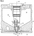
Fig. 2 is a diagrammatic cross-sectional view of the cylinder head with an installed pre-combustion chamber assembly shown in greater detail; -
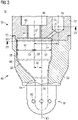
Fig. 3 is a partial cut view of the pre-combustion chamber assembly ofFig. 2 ; and -
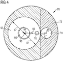
Fig. 4 is a cross-sectional view of the pre-combustion chamber assembly ofFig. 3 taken along line IV - IV ofFig. 3 . - The following is a detailed description of exemplary embodiments of the present disclosure. The exemplary embodiments described therein and illustrated in the drawings are intended to teach the principles of the present disclosure, enabling those of ordinary skill in the art to implement and use the present disclosure in many different environments and for many different applications. Therefore, the exemplary embodiments are not intended to be, and should not be considered as, a limiting description of the scope of patent protection. Rather, the scope of patent protection shall be defined by the appended claims.
- The present disclosure is based at least in part on the realization that asymmetrically arranging a pre-combustion chamber within a precombustion chamber assembly with respect to a longitudinally axis of the precombustion chamber assembly and providing a ignition point lying on a central axis of the pre-combustion chamber may support in stabilizing a combustion event within the pre-combustion chamber. In particular, the combustion event is provided symmetrically within the pre-combustion chamber and, hence, extinguishing of flames generated during the combustion event may be prevent due to a uniform distance of the ignition point to the inner walls of the combustion chamber. More particularly, it is preferable that the distance between the ignition point and the inner walls of the combustion chamber is as great as possible for preventing the flames from being extinguished too early during the ignition event. The better the combustion within the pre-combustion chamber with respect to efficiency, the better the combustion within the main combustion chamber with respect to efficiency.
- Within the meaning of the present disclosure, a "central axis" describes an axis of symmetry of a respective element or portion. That is that an element or portion having a "central axis" is substantially symmetrical with respect to said axis. In particular, an element or portion having a "central axis" is rotationally symmetrical with respect to said axis.
- Referring now to the drawings, an exemplary embodiment of an
internal combustion engine 10 is illustrated inFig. 1 . Theinternal combustion engine 10 may include features not shown, such as fuel systems, air systems, cooling systems, peripheries, drivetrain components, turbochargers, etc. For the purpose of the present disclosure, theinternal combustion engine 10 is considered as a four-stroke gaseous fuel internal combustion engine. One skilled in the art will recognize, however, that the gaseous fuelinternal combustion engine 10 may be any type of engine (two-stroke, turbine, gas, diesel, natural gas, propane, etc.) that would utilize a pre-combustion chamber. Furthermore, theinternal combustion engine 10 may be of any size, with any number of cylinders, and in any configuration ("V", in-line, radial, etc.). Theinternal combustion engine 10 may be used to power any machine or other device, including locomotive applications, on-highway trucks or vehicles, off-highway trucks or machines, earth moving equipment, generators, aerospace applications, marine applications, pumps, stationary equipment, or other engine powered applications. - The
internal combustion engine 10 may include anengine block 12 having a plurality of cylinders 14 (one of which is illustrated inFig. 1 ). Apiston 16 may be slidably disposed within the cylinder (or cylinder liner) 14 to reciprocate between a top dead center position and a bottom dead center position. A connectingrod 18 may connect thepiston 16 to aneccentric crankpin 20 of acrankshaft 22 such that reciprocating motion of the piston may result in rotation of thecrankshaft 22. - The
internal combustion engine 10 may also include acylinder head 24 engaged with theengine block 12 to cover thecylinder 14, thereby delimiting amain combustion chamber 26. Thecylinder head 24 may define intake andexhaust openings 28 that may allow intake gases into themain combustion chamber 26 and exhaust gases out of themain combustion chamber 26, respectively.Engine valves 30 may be positioned to selectively open and close theopenings 28. Eachcylinder 14 may include multiple intake andexhaust openings 28. - The
internal combustion engine 10 may include a series of valve actuation assemblies 40 (one of which is illustrated inFig. 1 ). The multiplevalve actuation assemblies 40 may be provided percylinder 14. For example, one valve actuation assembly may be used to open and close the intake valves and another valve actuation assembly may be provided to open and close the exhaust valves. - The
valve actuation assembly 40 may include arocker arm 46. Therocker arm 46 may be pivotally mounted in thecylinder head 24 and may attach to theengine valves 30 at one end and may attach to apush rod 48 at the other end. Oscillation ofrocker arm 46 about itspivot point 50 may cause thevalves 30 to move between an open position and a closed position. Thevalve actuation assembly 40 may also include valve springs 52 that may bias thevalves 30 toward the closed position (i.e. closing the intake and exhaust openings 28). - The other end of the
push rod 48 may engage alifter 54 which may engage acamshaft 56. Thecamshaft 56 may operatively engage thecrankshaft 22. Thecamshaft 56 may be connected withcrankshaft 22 in any manner readily apparent to one skilled in the art where rotation of thecrankshaft 22 may result in rotation of thecamshaft 56. For example,camshaft 56 may be connected to crankshaft 22 through a gear train (not shown). - As shown in
Fig. 1 , afirst cam lobe 58 may be disposed on thecamshaft 56 to engage thelifter 54. One skilled in the art may recognize that thecamshaft 56 may include additional cam lobes to engage with other lifters in order to actuate additional engine valves. - The
internal combustion engine 10 may also include a precombustion chamber assembly 60 (also referred to as pre-combustion chamber ignition device), which is positioned within thecylinder head 24 between thevalves 30. Thepre-combustion chamber assembly 60 may be configured in a variety of ways. Any assembly capable of being positioned in thecylinder head 24 to support a combustion event outside of themain combustion chamber 26, and direct the combustion into themain combustion chamber 26 may be used. - With reference to
Fig. 2 , thepre-combustion chamber assembly 60 ofFig. 1 is shown in greater detail. Thepre-combustion chamber assembly 60 defining a longitudinalcentral axis 63 may extend from thecylinder head 24 into themain combustion chamber 26. In the depicted embodiment, theprecombustion chamber assembly 60 comprises a pre-combustion chamberupper section 70 and a pre-combustion chamberlower section 80 detachably mounted to the pre-combustion chamberupper section 70. In some further embodiments, the pre-combustion chamberlower section 80 may be mounted to the precombustion chamberupper section 70 via, for example, welding or soldering. - As illustrated in
Fig. 2 , the pre-combustion chamberupper section 70 is disposed above the pre-combustion chamberlower section 80. InFig. 2 , a separation between the pre-combustion chamberupper section 70 and the precombustion chamberlower section 80 is indicated by a dashed line C. In some embodiments, thepre-combustion chamber assembly 60 may be a one-piece element manufactured by, for example, metal sintering, moulding, or any other suitable process. - The
pre-combustion chamber assembly 60 is attached to thecylinder head 24 via, for example, afastening device 61. In the assembled state, thefastening device 61 may at least partially press thepre-combustion chamber assembly 60 towards the main combustion chamber 26 (inFig. 2 in a downward direction). On the opposite side, thepre-combustion chamber assembly 60 contacts aflange 114, such that the pre-combustion chamber upper andlower sections lower sections upper section 70 may be generally cylindrical and may be made of any suitable material. - The
flange 114 is sealed against themain combustion chamber 26. Theflange 114 extends transversely relative to the longitudinalcentral axis 63 and is provided to seal against a sealingsurface 116 provided in thecylinder head 24 to prevent leakage between themain combustion chamber 26 and first and second coolingfluid passages - The pre-combustion chamber
upper section 70 is configured to accommodate an ignition device, such as, for example, aspark plug 62 therein such that a sparking end of thespark plug 62 at least partially protrudes into apre-combustion chamber 90 provided within thepre-combustion chamber assembly 60. Thespark plug 62 in the context of this invention may mean any suitable ignition device available in the prior art, such as, for instance, a plasma generator, a laser ignition device, a pilot fuel injector, a glow plug, or a glow pencil. - The pre-combustion chamber
lower section 80 is generally cylindrical and is mountable to the pre-combustion chamberupper section 70. Preferably, the pre-combustion chamberlower section 80 may be detachably mountable to the pre-combustion chamberupper section 70. This may allow replacing of, for example, the pre-combustion chamberlower section 80 by a new pre-combustion chamber lower section in the case of wear of the pre-combustion chamberlower section 80, especially in the case of wear of apre-combustion chamber tip 81 including a plurality offlow transfer passages 83. For instance, after a usage time of, for example, about 15.000 hours of engine operation, the pre-combustion chamberlower section 80 may be replaced. The pre-combustion chamberlower section 80 may be cast to the general configuration and subsequently machined to final dimensions where required. In some embodiments, the pre-combustion chamberlower section 80 may be machined out of a solid material block. In some further embodiments, the pre-combustion chamberlower section 80 may be sintered, or manufactured in any other suitable way known in the art. - The pre-combustion chamber
upper section 70 may have a stepped bore 64 that may be adapted to receive thespark plug 62. The stepped bore 64 may have an ignitiondevice accommodation portion 66, such as a mounting bore adapted to receive an end of thespark plug 62. The ignitiondevice accommodation portion 66 may include a thread adapted to mate with threads on the end of thespark plug 62. The stepped bore 64 may define a sealingsurface 65 that may be adapted to sealingly contact thespark plug 62. The ignitiondevice accommodation portion 66 may have any suitable configuration for accommodating the ignition device. - Referring to
Fig. 3 , a partial cut view of thepre-combustion chamber assembly 60 is illustrated. The pre-combustion chamberlower section 80 includes thepre-combustion chamber tip 81 which is generally cylindrical and which may at least partially protrude into themain combustion chamber 26 through abore 120 provided in the cylinder head 24 (seeFig. 2 ). - The pre-combustion chamber
upper section 70 and the precombustion chamberlower section 80 each define at least a portion of theprecombustion chamber 90. Particularly, the pre-combustion chamberlower section 80 defines at least a portion of thepre-combustion chamber 90, and the precombustion chamberupper section 70 defines a remaining portion of theprecombustion chamber 90. Thus, the pre-combustion chamber upper andlower sections pre-combustion chamber 90. - The
pre-combustion chamber 90 includes amain portion 92, ariser passage 94, and anintermediate portion 96 fluidly interconnected between themain portion 92 and theriser passage 94. InFig. 3 , themain portion 92, theriser passage 94, and theintermediate portion 96 are indicated in dash-two-dot lines. As shown inFig. 2 , the electrode end of thespark plug 62 at least partially protrudes into thepre-combustion chamber 90, particularly into themain portion 92. - The
pre-combustion chamber tip 81 having a substantially domelike shape includes a plurality of spaced apart, particularly radially orientedflow transfer passages 83. In some embodiments, the plurality offlow transfer passages 83 may extend tangentially with respect to a circle about thelongitudinal axis 63. - The plurality of
flow transfer passages 83 fluidly connects theprecombustion chamber 90, particularly theriser passage 94, to themain combustion chamber 26. The plurality offlow transfer passages 83 is configured to direct burning fuel, for example, expanding gases from thepre-combustion chamber 90 in a predetermined pattern into themain combustion chamber 26 and to direct an air/fuel mixture from themain combustion chamber 26 into thepre-combustion chamber 90. - The pre-combustion chamber
upper section 70 includes a precombustion chamberupper section body 72 and a fuelsupply accommodation portion 74 fluidly connected to thepre-combustion chamber 90 via afuel supply channel 76. The fuelsupply accommodation portion 74 is further fluidly connected to a fuel system (not explicitly shown in the drawings) including, for example, a fuel reservoir, fuel pumps, control valves, and further elements configured to provide fuel, such as, for example, gaseous fuel, to theprecombustion chamber 90. In some embodiments, the pre-combustion chamberupper section 70 may include more than one fuelsupply accommodation portion 74. The fuelsupply accommodation portion 74 is configured to accommodate, for example, a gaseous fuel valve (not shown in the drawings) and to supply a predetermined amount of gaseous fuel into thepre-combustion chamber 90. The gaseous fuel valve may be configured to control the supply of gaseous fuel into thepre-combustion chamber 90. - As shown, the fuel
supply accommodation portion 74 includes acentral axis 75 extending substantially in parallel to the longitudinalcentral axis 63 with a predetermined offset 77. In some embodiments, thecentral axis 75 of the fuelsupply accommodation portion 74 may extend obliquely and inclined with respect to the longitudinalcentral axis 63. - The predetermined amount of gaseous fuel supplied into the
main portion 92 may be configured to at least locally enrich the combustion mixture within thepre-combustion chamber 90, particularly within themain portion 92. - The pre-combustion chamber
upper section 70 is mountable to the pre-combustion chamberlower section 80 via, for instance, welding, soldering, screwing, bolting, form-fitting, or any other suitable fixing means. The precombustion chamberlower section 80 includes a pre-combustion chamberlower section body 82 and an annular protrusion 84 configured to engage and match with anannular recess 73 of the pre-combustion chamberupper section body 72. For example, the pre-combustion chamber upper andlower sections annular recess 73, respectively. In some embodiments, the pre-combustion chamber upper andlower sections lower sections - With additional reference to
Fig. 4 , it can be seen that themain portion 92 of thepre-combustion chamber 90 is substantially cylindrical with a substantially circular cross-section and has a main portioncentral axis 93 extending substantially in parallel to the longitudinalcentral axis 63 with a predetermined offset 91. Thus, themain portion 92 is not centrally and not symmetrically provided in the pre-combustion chamber upper andlower sections central axis 63. In further embodiments, the substantially cylindricalmain portion 92 may have any other suitable cross-sectional shape, such as, for instance, a rectangular, square, and oval. - As also shown in
Fig. 4 , theriser passage 94 is substantially cylindrical with a substantially circular cross-section and has a riser passagecentral axis 95 extending coaxially with respect to the longitudinalcentral axis 63. Thus, theriser passage 94 is centrally and symmetrically provided in the precombustion chamberlower section 80 with respect to the longitudinalcentral axis 63. As shown in the embodiment ofFigs. 3 and4 , the riser passagecentral axis 95 is substantially coaxial with respect to the longitudinalcentral axis 63, that is that the riser passagecentral axis 95 is coincident with thelongitudinal axis 63. The riser passagecentral axis 95 extends substantially in parallel to the main portioncentral axis 93 with the predetermined offset 91. - In some embodiments, the riser passage
central axis 95 may extend obliquely and inclined with respect to the longitudinalcentral axis 63. In such case, a tumble flow imparted into the combustion mixture flowing from themain combustion chamber 26 into thepre-combustion chamber 90 during a compression stroke of theinternal combustion engine 10 may be enhanced. - As indicated in
Fig. 3 , the ignitiondevice accommodation portion 66 includes acentral axis 67 extending substantially in parallel to the longitudinalcentral axis 63 and coaxially with respect to the main portioncentral axis 93. That is that thecentral axis 67 is coincident with the longitudinalcentral axis 63. Specifically, thespark plug 62 is mounted to the ignitiondevice accommodation portion 66 along the central axis 67 (seeFig. 2 ). - The
spark plug 62 is configured to generate a spark within themain portion 92 for initiating a combustion event within themain portion 92 at anignition point 99. As shown inFigs. 3 and4 , theignition point 99 lies on both thecentral axis 67 of the ignitiondevice accommodation portion 66 and the main portioncentral axis 93 of themain portion 92. Thus, aradial distance 97 between theignition point 99 and an inner wall of thepre-combustion chamber 90 is equal in each radial direction with respect to the main portioncentral axis 93. Hence, theignition point 99 is centrally provided within themain portion 92 with respect to the main portioncentral axis 93. - In some embodiments, the
central axis 67 of the ignitiondevice accommodation portion 66 may extend obliquely with respect to the main portioncentral axis 93 and the longitudinalcentral axis 63. In particular, thespark plug 62 may extend obliquely with respect to the longitudinalcentral axis 63 such that theignition point 99 lies on the main portioncentral axis 93 and, hence, centrally within themain portion 92 in a radial direction For example, thecentral axis 67 may extend obliquely with respect to the longitudinalcentral axis 63 with an angle between about 0° and about 30°. - In some embodiments, the
ignition point 99 may further be centrally arranged within themain portion 92 with respect to an axial direction of the main portioncentral axis 93. That is that theignition point 99 is centrally disposed between an upper end of themain portion 92 and a lower end of themain portion 92. - Referring to
Fig. 4 , a cut view of thepre-combustion chamber assembly 60 taken along line IV - IV ofFig. 3 is shown. InFig. 4 , it can be seen that themain portion 92 includes a substantially cylindrical shape with a substantially circular cross-section. Theignition point 99 lying on the main portioncentral axis 93 is, thus, centrally disposed within themain portion 92 and has aradial distance 97 to the inner wall of thepre-combustion chamber 90 that corresponds substantially to the radius of themain portion 92. - As further shown in
Fig. 4 , the pre-combustion chamberlower section body 82 includes, in a circumferential direction about the longitudinalcentral axis 63, a varying radials wall thickness. That is that the radial wall thickness of the pre-combustion chamberlower section body 82 with respect to the longitudinalcentral axis 63 is smaller on the left side inFig. 4 than on the right side inFig. 4 (see alsoFig. 3 ). - In the following, operation of the
internal combustion engine 10 comprising an exemplary disclosed pre-combustion chamber assembly is described with respect to the drawings. - During operation of the
internal combustion engine 10, especially during a compression stroke of one of thecylinders 14, at least some amount of an air/fuel mixture provided to thecylinder 14 through theengine valves 30 during an intake stroke is forced into thepre-combustion chamber 90 through theflow transfer passages 83. Then, for enriching the air/fuel mixture within theprecombustion chamber 90 in order to support the ignition event, at least some amount of fuel, such as gaseous fuel, is provided into thepre-combustion chamber 90, particularly into themain portion 92, via the gaseous fuel valve mounted to the fuelsupply accommodation portion 74, andfuel supply channel 76. The fuel supplied into thepre-combustion chamber 90 via the gaseous fuel valve and thefuel supply channel 76, respectively, may be supplied at a piston position in the vicinity of its bottom dead center. In some embodiments, the gaseous fuel supplied into thepre-combustion chamber 90 via the gaseous fuel valve and thefuel supply channel 76, respectively, may be supplied shortly before the ignition event is initiated. - Due to the arrangement of the fuel
supply accommodation portion 74 and thefuel supply channel 76, the ignitiondevice accommodation portion 66 needs to be displaced with respect to the longitudinalcentral axis 63 by the offset 91. Particularly, in view of the fuelsupply accommodation portion 74 and thefuel supply channel 76, there may be not enough space at the pre-combustion chamberupper section 70 for centrally providing the ignitiondevice accommodation portion 66. - Then, the ignition device mounted to the ignition
device accommodation portion 66 may initiate a combustion event at theignition point 99 lying on the main portioncentral axis 93 and, hence, in a central region of themain portion 92. Due to the central position of theignition point 99, a uniform and symmetric combustion event may be initiated within themain portion 92, such that the flames generated during the ignition event may expand in all spatial directions in an improved manner.. Moreover, the better the combustion within thepre-combustion chamber 90, the better the combustion within themain combustion chamber 26, in particular with respect to thermal efficiency. - Subsequently, the burning fuel may advance through the
intermediate portion 96, theriser passage 94, and the plurality offlow transfer passages 83 into themain combustion chamber 26, where the main combustion mixture may be ignited. - The asymmetric arrangement of the
pre-combustion chamber 90 with respect to the longitudinalcentral axis 63 may further have the effect of imparting at least partially a tumble flow into the combustion mixture pushed into thepre-combustion chamber 90 during a compression stroke. Specifically due to the asymmetric arrangement of themain portion 92 and the symmetric arrangement of theriser passage 94, the tumble flow may be imparted. - A tumble flow within the
pre-combustion chamber 90, particularly within themain portion 92, may have the advantageous effect that it is substantially stable. For example, for a pre-combustion chambermain portion 92 symmetrically disposed within the pre-combustion chamberlower section 80 with acombustion point 99 being offset thecentral axis 93, the combustion mixture flow flowing into themain portion 92 may detach from the inner wall in all spatial directions. To the contrary, for a pre-combustion chambermain porton 92 asymmetrically disposed within the pre-combustion chamberlower section 80 with acombustion point 99 centrally provided within the main portion 92 (as shown inFig. 3 ), the combustion mixture flow may detach in less spatial directions, that is that the combustion mixture flow may be substantially guided along at least a portion of the inner wall of thepre-combustion chamber 90 in a substantially defined manner.
Claims (11)
- A pre-combustion chamber assembly (60) for internal combustion engines (10) operating at least partly on gaseous fuel and having a cylinder (14) defining a main combustion chamber (26), the pre-combustion chamber assembly (60) extending along a longitudinal central axis (63) and comprising:a pre-combustion chamber upper section (70) extending along the longitudinal central axis (63), including an ignition device accommodation portion (66) configured to accommodate an ignition device (62) and including a fuel supply accommodation portion (74) for accommodating a fuel supply device, the fuel supply accommodation portion (74) having a central axis (75) extending in parallel to the longitudinal central axis (63) with a predetermined offset (77);a pre-combustion chamber lower section (80) extending along the longitudinal central axis (63) and connected to the pre-combustion chamber upper section (70), the pre-combustion chamber lower section (80) including a plurality of flow transfer passages (83);a pre-combustion chamber (90) delimited within the precombustion chamber upper section (70) and the pre-combustion chamber lower section (80) and fluidly connectable to the main combustion chamber (26) via the plurality of flow transfer passages (83), the pre-combustion chamber (90) including a main portion (92) having a main portion central axis (93) extending in parallel to the longitudinal central axis (63) with a predetermined offset (91); andan ignition device (62) mounted to the ignition device accommodation portion (66) and configured to initiate a combustion event at an ignition point (99) within the main portion (92), characterized in that the ignition point (99) lies substantially on the main portion central axis (93).
- The pre-combustion chamber assembly (60) of claim 1, wherein the ignition device is a spark plug (62) for generating a spark at the ignition point (99), the spark plug (62) having a spark plug central axis (67) extending in parallel to the longitudinal central axis (63) with the predetermined offset (91).
- The pre-combustion chamber assembly (60) of any one of the preceding claims, wherein the ignition device (62) includes an ignition device central axis (67) extending coaxially with respect to the main portion central axis (93).
- The pre-combustion chamber assembly (60) of any one of the preceding claims, wherein the pre-combustion chamber (90) further includes a riser passage (94) fluidly interconnected between the main portion (92) and the plurality of flow transfer passages (83), the riser passage (94) having a riser passage central axis (95) extending in parallel to the main portion central axis (93) with the predetermined offset (91).
- The pre-combustion chamber assembly (60) of claim 4, wherein the riser passage central axis (95) extends coaxially with respect to the longitudinal central axis (63).
- The pre-combustion chamber assembly (60) of any one of the preceding claims, further comprising a gaseous fuel valve mounted to the fuel supply accommodation portion (74) along the fuel supply accommodation portion central axis (75).
- The pre-combustion chamber assembly (60) of claim 6, wherein the gaseous fuel valve is configured to supply a predetermined amount of gaseous fuel to the main portion (92) via a fuel supply channel (76) fluidly connecting the fuel supply accommodation portion (74) to the main portion (92).
- An internal combustion engine (10) operating at least partly on gaseous fuel, the internal combustion engine (10) comprising:a cylinder (14) defining a main combustion chamber (26);a cylinder head (24) delimiting the main combustion chamber (26) at a top end; anda pre-combustion chamber assembly (60) according to any one of the preceding claims, the pre-combustion chamber assembly (60) being mounted to the cylinder head (24) and configured to initiate a main combustion event within the main combustion chamber (26).
- A method for operating an internal combustion engine (10) operating at least partly on gaseous fuel and that includes a main combustion chamber (26) and a pre-combustion chamber assembly (60) including a longitudinal central axis (63) and a pre-combustion chamber (90) with a main portion (92) having a main portion central axis (93) extending substantially in parallel to the longitudinal central axis (63) with a predetermined offset (91), the pre-combustion chamber (90) being fluidly connected to the main combustion chamber (26) via a plurality of flow transfer passages (83), the method comprising:supplying a combustion mixture into the main portion (92) via the plurality of flow transfer passages (83) during a compression stroke of the internal combustion engine (10);igniting the combustion mixture at an ignition point (99) within the main portion (92), andsupplying a predetermined amount of gaseous fuel into the main portion (92) for enriching the main portion (92) with gaseous fuel by means of a fuel supply accommodation portion (74) included in a pre-combustion chamber upper section (70) of the pre-combustion chamber assembly (60) and configured to accommodate a fuel supply device, the fuel supply accommodation portion (74) having a central axis (75) extending in parallel to the longitudinal central axis (63) with a predetermined offset (77), characterized in that the ignition point (99) lies on the main portion central axis (93).
- The method of claim 9, wherein igniting the combustion mixture includes generating a spark by a spark plug (62) having a spark plug central axis (67) extending coaxially with respect to the main portion central axis (93).
- The method of any one of claims 9 to 10, further comprising directing burning fuel through a riser passage (94) fluidly interconnected between the main portion (92) and the plurality of flow transfer passages (83), the riser passage (94) having a riser passage central axis (95) extending substantially in parallel to the main portion central axis (93).
Priority Applications (1)
| Application Number | Priority Date | Filing Date | Title |
|---|---|---|---|
| EP15176983.3A EP3118433B1 (en) | 2015-07-16 | 2015-07-16 | Pre-combustion chamber assembly for internal combustion engines |
Applications Claiming Priority (1)
| Application Number | Priority Date | Filing Date | Title |
|---|---|---|---|
| EP15176983.3A EP3118433B1 (en) | 2015-07-16 | 2015-07-16 | Pre-combustion chamber assembly for internal combustion engines |
Publications (2)
| Publication Number | Publication Date |
|---|---|
| EP3118433A1 EP3118433A1 (en) | 2017-01-18 |
| EP3118433B1 true EP3118433B1 (en) | 2022-08-31 |
Family
ID=53761956
Family Applications (1)
| Application Number | Title | Priority Date | Filing Date |
|---|---|---|---|
| EP15176983.3A Active EP3118433B1 (en) | 2015-07-16 | 2015-07-16 | Pre-combustion chamber assembly for internal combustion engines |
Country Status (1)
| Country | Link |
|---|---|
| EP (1) | EP3118433B1 (en) |
Families Citing this family (5)
| Publication number | Priority date | Publication date | Assignee | Title |
|---|---|---|---|---|
| JP6762712B2 (en) | 2015-12-21 | 2020-09-30 | 三菱重工エンジン&ターボチャージャ株式会社 | Sub-chamber engine |
| CN107091145A (en) * | 2017-06-07 | 2017-08-25 | 哈尔滨工程大学 | A kind of precombustion chamber of marine large-diameter gas engine |
| AT523918B1 (en) * | 2020-08-10 | 2022-01-15 | Avl List Gmbh | CYLINDER HEAD |
| CN113982740B (en) * | 2021-11-18 | 2022-08-26 | 山东大学 | Pre-combustion chamber for engine combustion system, combustion system and working method |
| CN115111048B (en) * | 2022-01-28 | 2023-09-19 | 长城汽车股份有限公司 | Initiative precombustion chamber, ignition mechanism and automobile engine |
Citations (1)
| Publication number | Priority date | Publication date | Assignee | Title |
|---|---|---|---|---|
| EP3176423A1 (en) * | 2014-07-31 | 2017-06-07 | Denso Corporation | Laser ignition device |
Family Cites Families (13)
| Publication number | Priority date | Publication date | Assignee | Title |
|---|---|---|---|---|
| US3406667A (en) * | 1966-09-29 | 1968-10-22 | Alvin W. Evans | Ignition amplifying apparatus |
| US3970053A (en) | 1973-11-05 | 1976-07-20 | Fiat Societa Per Azioni | Internal combustion engines |
| JPS5281405A (en) | 1975-12-26 | 1977-07-07 | Toyota Motor Corp | Internal combustion engine equipped with subchamber and its combustion control method |
| FR2630497B1 (en) | 1988-04-21 | 1993-05-28 | Peugeot | COMPRESSION IGNITION ENGINE HAVING A PRECHAMBER HAVING THE TRANSFER CHANNEL IS STRAIGHT AND INCLINED |
| US4903656A (en) * | 1988-12-29 | 1990-02-27 | Yanmar Deisel Engine Co., Ltd. | Gas engine |
| US5230313A (en) * | 1992-11-23 | 1993-07-27 | Dresser-Rand Company | Gas engine cylinder head, and a method of retrofitting the head with a precombustion chamber unit |
| US6513483B2 (en) | 2001-02-07 | 2003-02-04 | Cooper Cameron Corporation | Pre-combustion chamber for an internal combustion engine |
| DE112005000152T5 (en) | 2004-03-30 | 2007-02-15 | Aleksandr Nikolaevic Sergeev | Internal combustion engine and the method of its control |
| US8028674B2 (en) | 2007-08-07 | 2011-10-04 | Lytesyde, Llc | Fuel processor apparatus and method |
| FI123915B (en) | 2008-03-03 | 2013-12-13 | Waertsilae Finland Oy | Förkammararrangemang |
| AT510435B1 (en) | 2010-11-02 | 2012-04-15 | Ge Jenbacher Gmbh & Co Ohg | reciprocating engine |
| AT13172U1 (en) * | 2011-12-28 | 2013-07-15 | Ge Jenbacher Gmbh & Co Ohg | Pre-chamber system for an internal combustion engine |
| EP2700796B1 (en) * | 2012-08-22 | 2016-08-10 | Caterpillar Motoren GmbH & Co. KG | Pre-combustion chamber of an internal combustion engine and method of operating the same |
-
2015
- 2015-07-16 EP EP15176983.3A patent/EP3118433B1/en active Active
Patent Citations (1)
| Publication number | Priority date | Publication date | Assignee | Title |
|---|---|---|---|---|
| EP3176423A1 (en) * | 2014-07-31 | 2017-06-07 | Denso Corporation | Laser ignition device |
Also Published As
| Publication number | Publication date |
|---|---|
| EP3118433A1 (en) | 2017-01-18 |
Similar Documents
| Publication | Publication Date | Title |
|---|---|---|
| EP3012431B1 (en) | Pre-combustion chamber assembly for internal combustion engines | |
| EP2700796B1 (en) | Pre-combustion chamber of an internal combustion engine and method of operating the same | |
| EP3118433B1 (en) | Pre-combustion chamber assembly for internal combustion engines | |
| CN105298624B (en) | Igniter with precombustion chamber | |
| CN111164285B (en) | Internal combustion engine for a motor vehicle | |
| EP2935865B1 (en) | Ignition plug tip of an internal combustion engine | |
| EP2927458A1 (en) | Pre-chamber with flow transfer passages | |
| EP2573355B1 (en) | Pre-combustion chamber tip | |
| EP3051092B1 (en) | Cooling of pre-chamber in internal combustion engine | |
| EP3907384B1 (en) | Prechamber sparkplug having electrodes located for inhibiting flame kernel quenching | |
| US20160363094A1 (en) | Spark plug assembly having improved cooling | |
| CN114439600A (en) | Pre-chamber assembly | |
| JP2020037939A (en) | Pre-chamber | |
| JP2019116865A (en) | Internal combustion engine | |
| JP3885071B2 (en) | Hydrogen engine | |
| CN115777041A (en) | Pre-chamber spark plug with optimized cap and internal combustion engine | |
| WO2017102465A1 (en) | Spark plug | |
| EP3431745A1 (en) | Spark plug for an internal combustion engine | |
| WO2022054344A1 (en) | Two-stroke engine provided with ignition device | |
| JP6565968B2 (en) | engine | |
| GB2545479A (en) | Pre-combustion chamber | |
| WO2022150757A1 (en) | Passive prechamber lean burn combustion system | |
| KR20090124492A (en) | Engine with plural cylinder |
Legal Events
| Date | Code | Title | Description |
|---|---|---|---|
| PUAI | Public reference made under article 153(3) epc to a published international application that has entered the european phase |
Free format text: ORIGINAL CODE: 0009012 |
|
| STAA | Information on the status of an ep patent application or granted ep patent |
Free format text: STATUS: THE APPLICATION HAS BEEN PUBLISHED |
|
| AK | Designated contracting states |
Kind code of ref document: A1 Designated state(s): AL AT BE BG CH CY CZ DE DK EE ES FI FR GB GR HR HU IE IS IT LI LT LU LV MC MK MT NL NO PL PT RO RS SE SI SK SM TR |
|
| AX | Request for extension of the european patent |
Extension state: BA ME |
|
| STAA | Information on the status of an ep patent application or granted ep patent |
Free format text: STATUS: REQUEST FOR EXAMINATION WAS MADE |
|
| 17P | Request for examination filed |
Effective date: 20170717 |
|
| RBV | Designated contracting states (corrected) |
Designated state(s): AL AT BE BG CH CY CZ DE DK EE ES FI FR GB GR HR HU IE IS IT LI LT LU LV MC MK MT NL NO PL PT RO RS SE SI SK SM TR |
|
| STAA | Information on the status of an ep patent application or granted ep patent |
Free format text: STATUS: EXAMINATION IS IN PROGRESS |
|
| 17Q | First examination report despatched |
Effective date: 20181122 |
|
| STAA | Information on the status of an ep patent application or granted ep patent |
Free format text: STATUS: EXAMINATION IS IN PROGRESS |
|
| STAA | Information on the status of an ep patent application or granted ep patent |
Free format text: STATUS: EXAMINATION IS IN PROGRESS |
|
| GRAP | Despatch of communication of intention to grant a patent |
Free format text: ORIGINAL CODE: EPIDOSNIGR1 |
|
| STAA | Information on the status of an ep patent application or granted ep patent |
Free format text: STATUS: GRANT OF PATENT IS INTENDED |
|
| INTG | Intention to grant announced |
Effective date: 20220405 |
|
| GRAS | Grant fee paid |
Free format text: ORIGINAL CODE: EPIDOSNIGR3 |
|
| GRAA | (expected) grant |
Free format text: ORIGINAL CODE: 0009210 |
|
| STAA | Information on the status of an ep patent application or granted ep patent |
Free format text: STATUS: THE PATENT HAS BEEN GRANTED |
|
| AK | Designated contracting states |
Kind code of ref document: B1 Designated state(s): AL AT BE BG CH CY CZ DE DK EE ES FI FR GB GR HR HU IE IS IT LI LT LU LV MC MK MT NL NO PL PT RO RS SE SI SK SM TR |
|
| REG | Reference to a national code |
Ref country code: CH Ref legal event code: EP Ref country code: GB Ref legal event code: FG4D |
|
| REG | Reference to a national code |
Ref country code: AT Ref legal event code: REF Ref document number: 1515442 Country of ref document: AT Kind code of ref document: T Effective date: 20220915 Ref country code: DE Ref legal event code: R096 Ref document number: 602015080549 Country of ref document: DE |
|
| REG | Reference to a national code |
Ref country code: IE Ref legal event code: FG4D |
|
| REG | Reference to a national code |
Ref country code: LT Ref legal event code: MG9D |
|
| REG | Reference to a national code |
Ref country code: NL Ref legal event code: MP Effective date: 20220831 |
|
| PG25 | Lapsed in a contracting state [announced via postgrant information from national office to epo] |
Ref country code: SE Free format text: LAPSE BECAUSE OF FAILURE TO SUBMIT A TRANSLATION OF THE DESCRIPTION OR TO PAY THE FEE WITHIN THE PRESCRIBED TIME-LIMIT Effective date: 20220831 Ref country code: RS Free format text: LAPSE BECAUSE OF FAILURE TO SUBMIT A TRANSLATION OF THE DESCRIPTION OR TO PAY THE FEE WITHIN THE PRESCRIBED TIME-LIMIT Effective date: 20220831 Ref country code: NO Free format text: LAPSE BECAUSE OF FAILURE TO SUBMIT A TRANSLATION OF THE DESCRIPTION OR TO PAY THE FEE WITHIN THE PRESCRIBED TIME-LIMIT Effective date: 20221130 Ref country code: LV Free format text: LAPSE BECAUSE OF FAILURE TO SUBMIT A TRANSLATION OF THE DESCRIPTION OR TO PAY THE FEE WITHIN THE PRESCRIBED TIME-LIMIT Effective date: 20220831 Ref country code: LT Free format text: LAPSE BECAUSE OF FAILURE TO SUBMIT A TRANSLATION OF THE DESCRIPTION OR TO PAY THE FEE WITHIN THE PRESCRIBED TIME-LIMIT Effective date: 20220831 Ref country code: FI Free format text: LAPSE BECAUSE OF FAILURE TO SUBMIT A TRANSLATION OF THE DESCRIPTION OR TO PAY THE FEE WITHIN THE PRESCRIBED TIME-LIMIT Effective date: 20220831 Ref country code: ES Free format text: LAPSE BECAUSE OF FAILURE TO SUBMIT A TRANSLATION OF THE DESCRIPTION OR TO PAY THE FEE WITHIN THE PRESCRIBED TIME-LIMIT Effective date: 20220831 |
|
| REG | Reference to a national code |
Ref country code: AT Ref legal event code: MK05 Ref document number: 1515442 Country of ref document: AT Kind code of ref document: T Effective date: 20220831 |
|
| PG25 | Lapsed in a contracting state [announced via postgrant information from national office to epo] |
Ref country code: PL Free format text: LAPSE BECAUSE OF FAILURE TO SUBMIT A TRANSLATION OF THE DESCRIPTION OR TO PAY THE FEE WITHIN THE PRESCRIBED TIME-LIMIT Effective date: 20220831 Ref country code: IS Free format text: LAPSE BECAUSE OF FAILURE TO SUBMIT A TRANSLATION OF THE DESCRIPTION OR TO PAY THE FEE WITHIN THE PRESCRIBED TIME-LIMIT Effective date: 20221231 Ref country code: HR Free format text: LAPSE BECAUSE OF FAILURE TO SUBMIT A TRANSLATION OF THE DESCRIPTION OR TO PAY THE FEE WITHIN THE PRESCRIBED TIME-LIMIT Effective date: 20220831 Ref country code: GR Free format text: LAPSE BECAUSE OF FAILURE TO SUBMIT A TRANSLATION OF THE DESCRIPTION OR TO PAY THE FEE WITHIN THE PRESCRIBED TIME-LIMIT Effective date: 20221201 |
|
| PG25 | Lapsed in a contracting state [announced via postgrant information from national office to epo] |
Ref country code: SM Free format text: LAPSE BECAUSE OF FAILURE TO SUBMIT A TRANSLATION OF THE DESCRIPTION OR TO PAY THE FEE WITHIN THE PRESCRIBED TIME-LIMIT Effective date: 20220831 Ref country code: RO Free format text: LAPSE BECAUSE OF FAILURE TO SUBMIT A TRANSLATION OF THE DESCRIPTION OR TO PAY THE FEE WITHIN THE PRESCRIBED TIME-LIMIT Effective date: 20220831 Ref country code: PT Free format text: LAPSE BECAUSE OF FAILURE TO SUBMIT A TRANSLATION OF THE DESCRIPTION OR TO PAY THE FEE WITHIN THE PRESCRIBED TIME-LIMIT Effective date: 20230102 Ref country code: DK Free format text: LAPSE BECAUSE OF FAILURE TO SUBMIT A TRANSLATION OF THE DESCRIPTION OR TO PAY THE FEE WITHIN THE PRESCRIBED TIME-LIMIT Effective date: 20220831 Ref country code: CZ Free format text: LAPSE BECAUSE OF FAILURE TO SUBMIT A TRANSLATION OF THE DESCRIPTION OR TO PAY THE FEE WITHIN THE PRESCRIBED TIME-LIMIT Effective date: 20220831 Ref country code: AT Free format text: LAPSE BECAUSE OF FAILURE TO SUBMIT A TRANSLATION OF THE DESCRIPTION OR TO PAY THE FEE WITHIN THE PRESCRIBED TIME-LIMIT Effective date: 20220831 |
|
| PG25 | Lapsed in a contracting state [announced via postgrant information from national office to epo] |
Ref country code: SK Free format text: LAPSE BECAUSE OF FAILURE TO SUBMIT A TRANSLATION OF THE DESCRIPTION OR TO PAY THE FEE WITHIN THE PRESCRIBED TIME-LIMIT Effective date: 20220831 Ref country code: EE Free format text: LAPSE BECAUSE OF FAILURE TO SUBMIT A TRANSLATION OF THE DESCRIPTION OR TO PAY THE FEE WITHIN THE PRESCRIBED TIME-LIMIT Effective date: 20220831 |
|
| REG | Reference to a national code |
Ref country code: DE Ref legal event code: R097 Ref document number: 602015080549 Country of ref document: DE |
|
| P01 | Opt-out of the competence of the unified patent court (upc) registered |
Effective date: 20230517 |
|
| PG25 | Lapsed in a contracting state [announced via postgrant information from national office to epo] |
Ref country code: NL Free format text: LAPSE BECAUSE OF FAILURE TO SUBMIT A TRANSLATION OF THE DESCRIPTION OR TO PAY THE FEE WITHIN THE PRESCRIBED TIME-LIMIT Effective date: 20220831 Ref country code: AL Free format text: LAPSE BECAUSE OF FAILURE TO SUBMIT A TRANSLATION OF THE DESCRIPTION OR TO PAY THE FEE WITHIN THE PRESCRIBED TIME-LIMIT Effective date: 20220831 |
|
| PLBE | No opposition filed within time limit |
Free format text: ORIGINAL CODE: 0009261 |
|
| STAA | Information on the status of an ep patent application or granted ep patent |
Free format text: STATUS: NO OPPOSITION FILED WITHIN TIME LIMIT |
|
| 26N | No opposition filed |
Effective date: 20230601 |
|
| PG25 | Lapsed in a contracting state [announced via postgrant information from national office to epo] |
Ref country code: SI Free format text: LAPSE BECAUSE OF FAILURE TO SUBMIT A TRANSLATION OF THE DESCRIPTION OR TO PAY THE FEE WITHIN THE PRESCRIBED TIME-LIMIT Effective date: 20220831 |
|
| PGFP | Annual fee paid to national office [announced via postgrant information from national office to epo] |
Ref country code: GB Payment date: 20230620 Year of fee payment: 9 |
|
| PGFP | Annual fee paid to national office [announced via postgrant information from national office to epo] |
Ref country code: DE Payment date: 20230620 Year of fee payment: 9 |
|
| PG25 | Lapsed in a contracting state [announced via postgrant information from national office to epo] |
Ref country code: MC Free format text: LAPSE BECAUSE OF FAILURE TO SUBMIT A TRANSLATION OF THE DESCRIPTION OR TO PAY THE FEE WITHIN THE PRESCRIBED TIME-LIMIT Effective date: 20220831 |
|
| PG25 | Lapsed in a contracting state [announced via postgrant information from national office to epo] |
Ref country code: MC Free format text: LAPSE BECAUSE OF FAILURE TO SUBMIT A TRANSLATION OF THE DESCRIPTION OR TO PAY THE FEE WITHIN THE PRESCRIBED TIME-LIMIT Effective date: 20220831 |
|
| REG | Reference to a national code |
Ref country code: CH Ref legal event code: PL |
|
| PG25 | Lapsed in a contracting state [announced via postgrant information from national office to epo] |
Ref country code: LU Free format text: LAPSE BECAUSE OF NON-PAYMENT OF DUE FEES Effective date: 20230716 |
|
| PG25 | Lapsed in a contracting state [announced via postgrant information from national office to epo] |
Ref country code: LU Free format text: LAPSE BECAUSE OF NON-PAYMENT OF DUE FEES Effective date: 20230716 |