WO2024224709A1 - テーブル移動機構およびそれを備えたインクジェットプリンタ - Google Patents
テーブル移動機構およびそれを備えたインクジェットプリンタ Download PDFInfo
- Publication number
- WO2024224709A1 WO2024224709A1 PCT/JP2024/000768 JP2024000768W WO2024224709A1 WO 2024224709 A1 WO2024224709 A1 WO 2024224709A1 JP 2024000768 W JP2024000768 W JP 2024000768W WO 2024224709 A1 WO2024224709 A1 WO 2024224709A1
- Authority
- WO
- WIPO (PCT)
- Prior art keywords
- base member
- slide
- shaft
- adjustment
- lifting
- Prior art date
- Legal status (The legal status is an assumption and is not a legal conclusion. Google has not performed a legal analysis and makes no representation as to the accuracy of the status listed.)
- Ceased
Links
Images





Classifications
-
- B—PERFORMING OPERATIONS; TRANSPORTING
- B41—PRINTING; LINING MACHINES; TYPEWRITERS; STAMPS
- B41J—TYPEWRITERS; SELECTIVE PRINTING MECHANISMS, i.e. MECHANISMS PRINTING OTHERWISE THAN FROM A FORME; CORRECTION OF TYPOGRAPHICAL ERRORS
- B41J11/00—Devices or arrangements of selective printing mechanisms, e.g. ink-jet printers or thermal printers, for supporting or handling copy material in sheet or web form
- B41J11/20—Platen adjustments for varying the strength of impression, for a varying number of papers, for wear or for alignment, or for print gap adjustment
-
- B—PERFORMING OPERATIONS; TRANSPORTING
- B41—PRINTING; LINING MACHINES; TYPEWRITERS; STAMPS
- B41J—TYPEWRITERS; SELECTIVE PRINTING MECHANISMS, i.e. MECHANISMS PRINTING OTHERWISE THAN FROM A FORME; CORRECTION OF TYPOGRAPHICAL ERRORS
- B41J11/00—Devices or arrangements of selective printing mechanisms, e.g. ink-jet printers or thermal printers, for supporting or handling copy material in sheet or web form
- B41J11/02—Platens
-
- B—PERFORMING OPERATIONS; TRANSPORTING
- B41—PRINTING; LINING MACHINES; TYPEWRITERS; STAMPS
- B41J—TYPEWRITERS; SELECTIVE PRINTING MECHANISMS, i.e. MECHANISMS PRINTING OTHERWISE THAN FROM A FORME; CORRECTION OF TYPOGRAPHICAL ERRORS
- B41J11/00—Devices or arrangements of selective printing mechanisms, e.g. ink-jet printers or thermal printers, for supporting or handling copy material in sheet or web form
- B41J11/02—Platens
- B41J11/06—Flat page-size platens or smaller flat platens having a greater size than line-size platens
-
- B—PERFORMING OPERATIONS; TRANSPORTING
- B41—PRINTING; LINING MACHINES; TYPEWRITERS; STAMPS
- B41J—TYPEWRITERS; SELECTIVE PRINTING MECHANISMS, i.e. MECHANISMS PRINTING OTHERWISE THAN FROM A FORME; CORRECTION OF TYPOGRAPHICAL ERRORS
- B41J11/00—Devices or arrangements of selective printing mechanisms, e.g. ink-jet printers or thermal printers, for supporting or handling copy material in sheet or web form
- B41J11/02—Platens
- B41J11/14—Platen-shift mechanisms; Driving gear therefor
-
- B—PERFORMING OPERATIONS; TRANSPORTING
- B41—PRINTING; LINING MACHINES; TYPEWRITERS; STAMPS
- B41J—TYPEWRITERS; SELECTIVE PRINTING MECHANISMS, i.e. MECHANISMS PRINTING OTHERWISE THAN FROM A FORME; CORRECTION OF TYPOGRAPHICAL ERRORS
- B41J2/00—Typewriters or selective printing mechanisms characterised by the printing or marking process for which they are designed
- B41J2/005—Typewriters or selective printing mechanisms characterised by the printing or marking process for which they are designed characterised by bringing liquid or particles selectively into contact with a printing material
- B41J2/01—Ink jet
-
- B—PERFORMING OPERATIONS; TRANSPORTING
- B41—PRINTING; LINING MACHINES; TYPEWRITERS; STAMPS
- B41J—TYPEWRITERS; SELECTIVE PRINTING MECHANISMS, i.e. MECHANISMS PRINTING OTHERWISE THAN FROM A FORME; CORRECTION OF TYPOGRAPHICAL ERRORS
- B41J25/00—Actions or mechanisms not otherwise provided for
- B41J25/001—Mechanisms for bodily moving print heads or carriages parallel to the paper surface
-
- B—PERFORMING OPERATIONS; TRANSPORTING
- B41—PRINTING; LINING MACHINES; TYPEWRITERS; STAMPS
- B41J—TYPEWRITERS; SELECTIVE PRINTING MECHANISMS, i.e. MECHANISMS PRINTING OTHERWISE THAN FROM A FORME; CORRECTION OF TYPOGRAPHICAL ERRORS
- B41J3/00—Typewriters or selective printing or marking mechanisms characterised by the purpose for which they are constructed
- B41J3/28—Typewriters or selective printing or marking mechanisms characterised by the purpose for which they are constructed for printing downwardly on flat surfaces, e.g. of books, drawings, boxes, envelopes, e.g. flat-bed ink-jet printers
-
- B—PERFORMING OPERATIONS; TRANSPORTING
- B65—CONVEYING; PACKING; STORING; HANDLING THIN OR FILAMENTARY MATERIAL
- B65H—HANDLING THIN OR FILAMENTARY MATERIAL, e.g. SHEETS, WEBS, CABLES
- B65H5/00—Feeding articles separated from piles; Feeding articles to machines
- B65H5/18—Feeding articles separated from piles; Feeding articles to machines by rotary dials or tables
Definitions
- the present invention relates to a table movement mechanism and an inkjet printer equipped with the same.
- Patent Document 1 discloses a table movement mechanism that includes a slide mechanism for moving a table unit, which includes a table on which a recording medium is placed, in a forward/backward direction, and a lifting mechanism for moving the table unit in an up/down direction.
- the table unit includes a table carriage that houses a lifting mechanism such as a lifting shaft and has an opening at the top, and a lifting case that has a table on which the media is placed.
- the lifting case is inserted into an opening formed in the table carriage.
- the lifting case is configured to be movable in the up/down direction relative to the table carriage.
- the slide mechanism moves the table carriage in the forward/backward direction.
- the lifting mechanism is housed inside the table carriage and moves the lifting case in the up/down direction. This allows the recording medium to be moved in the forward/backward direction and up/down directions.
- a lifting mechanism that moves the table unit up and down is mounted on a slide mechanism that moves the table unit back and forth.
- a lifting shaft for lifting the table unit is housed in the table carriage, and the height of the lifting case (table) can be adjusted relative to the slidable table carriage by the lifting case protruding upward from the table carriage. Therefore, the table carriage is formed in a box shape that can house the slide shaft, and the lifting case is formed in a box shape to ensure the movement of the table. Therefore, the table movement mechanism has a double box shape with the table carriage and the lifting case. Therefore, the size of the table movement mechanism is relatively large. Furthermore, because the size of the table movement mechanism is relatively large, the size of the inkjet printer equipped with the table movement mechanism is also relatively large.
- the present invention was made in consideration of these points, and its purpose is to provide a compact table movement mechanism and an inkjet printer equipped with the same.
- the table movement mechanism comprises a table on which a recording medium is placed, a slide mechanism for transporting the table in a horizontal first direction, and a lifting unit for adjusting the vertical height of the table.
- the slide mechanism comprises a slide rail for supporting the table and extending in the first direction, a first base member on which the slide rail is provided, and a transport mechanism for moving the table in the first direction along the slide rail relative to the first base member.
- the lifting unit comprises a lifting shaft that engages with the first base member and extends in the vertical direction, a second base member on which the lifting shaft is erected, and a lifting mechanism for moving the first base member in the vertical direction along the lifting shaft relative to the second base member.
- the table on which the recording medium is placed is moved by the slide mechanism and the lifting unit.
- the transport mechanism including the slide mechanism moves the table in the first direction along the slide rail relative to the first base member.
- the lifting mechanism including the lifting unit moves the first base member in the vertical direction along the lifting shaft relative to the second base member.
- the first base member moves in the vertical direction.
- the first base member supporting the table moves in the vertical direction relative to the second base member by the lifting unit. Therefore, since the lifting mechanism does not move in the first direction as in the conventional structure, a table carriage for moving the lifting mechanism in the first direction can be omitted, and it is sufficient to move the table itself (the first base member supporting the table) in the vertical direction. Therefore, there is no need to form the lifting mechanism into a double box shape. This allows the table moving mechanism to be made smaller.
- the present invention provides a compact table movement mechanism and an inkjet printer equipped with the same.
- FIG. 1 is a perspective view of a printer according to an embodiment.
- FIG. 2 is a perspective view of the inside of a printer according to an embodiment.
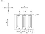
- FIG. 3 is a schematic diagram showing the configuration of the bottom surface of the head carriage according to the embodiment.
- FIG. 4 is a perspective view of a table according to an embodiment.
- FIG. 5 is a perspective view of a slide mechanism according to an embodiment.
- FIG. 6 is a schematic diagram showing the configuration of the bottom surface of the slide mechanism according to one embodiment.
- FIG. 7 is a schematic diagram of the second base member according to one embodiment as viewed from below.
- FIG. 8 is a partial cross-sectional view of the vicinity of the bush.
- FIG. 9 is a perspective view showing a part of a lifting unit and its periphery according to an embodiment.
- FIG. 10 is a side view of a table moving mechanism according to an embodiment.
- FIG. 11 is a perspective view of the inside of a printer according to the second embodiment.
- FIG. 12 is a perspective view showing a part of the lifting unit and its periphery according to the second embodiment.
- FIG. 13 is a partial cross-sectional view of the periphery of the guiding jig according to the second embodiment.
- FIG. 14 is a perspective view showing the guiding jig.
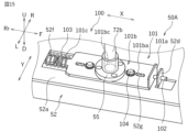
- FIG. 15 is a perspective view of the adjustment mechanism.
- FIG. 16 is a plan view of the adjustment mechanism and its periphery according to the second embodiment.
- FIG. 1 is a perspective view of a printer 10 according to this embodiment.
- the side away from the printer 10 is referred to as the front, and the side approaching the printer 10 is referred to as the rear.
- Left, right, top, and bottom refer to the left, right, top, and bottom of the printer 10 when viewed from the front.
- the symbols F, Rr, L, R, U, and D in the drawings refer to the front, back, left, right, top, and bottom, respectively.
- the symbol Y in the drawings indicates the main scanning direction.
- the main scanning direction Y is the left-right direction.
- the main scanning direction Y is an example of the second direction in the present invention.
- the symbol X indicates the sub-scanning direction.
- the sub-scanning direction X is the front-rear direction, and is perpendicular to the main scanning direction Y in a plan view.
- the sub-scanning direction X is an example of the first direction in the present invention.
- the symbol Z indicates the up-down direction.
- the above directions are merely defined for the convenience of explanation, and do not limit the installation mode of the printer 10 or the present invention in any way.
- the printer 10 is an inkjet printer.
- the printer 10 prints an image on the recording medium 5 by moving the recording medium 5 in the front-to-rear direction and ejecting ink from multiple ink heads 34 mounted on an ink head unit 30 that moves in the left-to-right direction.
- the recording medium 5 is, for example, recording paper.
- the recording medium 5 is not limited to recording paper.
- the recording medium 5 includes relatively thick materials such as sheets made of resin materials such as PVC and polyester, metal plates made of aluminum or iron, glass plates, and wooden plates.
- the recording medium 5 is an example of a workpiece.
- the recording medium 5 is an example of a medium.
- the printer 10 includes a main body case 12 (see FIG. 1), a main body frame 14, a carriage movement mechanism 20, an ink head unit 30, and a table movement mechanism 90.
- the table movement mechanism 90 includes a table 40, a slide mechanism 50, a lifting unit 60, a first side wall member 73, and a second side wall member 74.
- the main body case 12 is a box-shaped member that, together with the second base member 63 of the table movement mechanism 90 described later, forms a storage space for accommodating the main body frame 14, the carriage movement mechanism 20, the ink head unit 30, etc.
- a front cover 13C is provided in the center of the front of the main body case 12.
- a left cover 13L is provided on the left side of the front of the main body case 12.
- a right cover 13R is provided on the right side of the front of the main body case 12.
- the front cover 13C, the left cover 13L, and the right cover 13R are configured to be able to be opened and closed relative to the main body case 12.
- the front cover 13C is provided with a window 13W.
- the window 13W is formed, for example, of a transparent acrylic plate.
- the ink head unit 30 is disposed above the table 40.
- the ink head unit 30 is disposed inside the main body case 12 (see FIG. 1).
- the ink head unit 30 includes an ink head 34, a case 31, and a head carriage 32 on which the ink head 34 is mounted.
- the main body case 12 is not shown in FIG. 2.
- the main frame 14 is a structural member that extends upward in the main scanning direction Y from a second base member 63 (described later), and an opening 14H that penetrates the main frame 14 in the sub-scanning direction X is formed.
- the slide mechanism 50 is configured to pass through the opening 14H.
- the printer 10 has a guide rail 18 provided on the main frame 14.
- the guide rail 18 is supported by a second base member 63 (described later) via the main frame 14.
- the guide rail 18 extends in the main scanning direction Y.
- the guide rail 18 is provided along the front surface of the main frame 14.
- the guide rail 18 is disposed above the opening 14H.
- the guide rail 18 is disposed above the table 40.
- the head carriage 32 of the ink head unit 30 is slidably provided on the guide rail 18.
- the guide rail 18 guides the movement of the head carriage 32 in the main scanning direction Y.
- the case 31 is attached to the head carriage 32.
- the carriage movement mechanism 20 is a mechanism that moves the head carriage 32 in the main scanning direction Y relative to the recording medium 5 placed on the table 40.
- the configuration of the carriage movement mechanism 20 is not particularly limited.
- the carriage movement mechanism 20 includes a pulley 21, a pulley 22, a belt 23, and a head carriage motor 24.
- the left pulley 21 is provided to the left of the left end of the guide rail 18.
- the right pulley 22 is provided to the right of the right end of the guide rail 18.
- the belt 23 is wound around the pulleys 21 and 22.
- the head carriage motor 24 is connected to the right pulley 22. However, the head carriage motor 24 may be connected to the left pulley 21.
- the head carriage motor 24 is driven to rotate the pulley 22, causing the belt 23 to run between the pulleys 21 and 22.
- the head carriage 32 is attached to the belt 23.
- the head carriage 32 is connected to the guide rail 18 so that it can slide freely.
- the head carriage 32 is positioned above the table 40.
- An ink head 34 is mounted on the head carriage 32.
- the belt 23 runs when driven by the head carriage motor 24, and the head carriage 32 moves in the main scanning direction Y. As the head carriage 32 moves in the main scanning direction Y, the ink head 34 mounted on the head carriage 32 moves in the main scanning direction Y.
- the ink heads 34 are formed in a shape in which the length in the sub-scanning direction X is longer than the length in the main scanning direction Y.
- the ink heads 34 are each formed in the same shape and size.
- the ink heads 34 are provided with a plurality of nozzles 35 aligned in the sub-scanning direction X, and a nozzle surface 36 in which the plurality of nozzles 35 are formed.
- Each ink head 34 is provided with two nozzle rows each composed of the plurality of nozzles 35.
- the nozzles 35 eject ink onto the recording medium 5.
- the inside of the nozzles 35 is set to a negative pressure (pressure lower than atmospheric pressure).
- the ink head unit 30 is provided with three ink heads 34, but the number of ink heads 34 is not limited to three. Also, each ink head 34 is provided with two nozzle rows, but the number of nozzle rows is not limited to two.
- the slide mechanism 50 is a mechanism for moving the table 40 shown in FIG. 4 in the sub-scanning direction X as shown in FIG. 5.
- the slide mechanism 50 includes a slide rail 51 for supporting the table 40 (see FIG. 4) so that it can move, a first base member 52 on which the slide rail 51 is provided, a transport mechanism 53 for moving the table 40 in the sub-scanning direction X, and a transport motor 54 (see FIG. 5).
- the lifting unit 60 includes a lifting shaft 72, a holder 57, a nut 56 (see FIG. 8), a bush 55, a lifting mechanism 61 for moving the first base member 52 up and down along the lifting shaft, a lifting motor 62 for driving the lifting mechanism, and a second base member 63 on which the lifting shaft 72 is erected.
- the recording medium 5 is placed on the table 40.
- the table 40 is disposed below the ink head 34.
- the table 40 includes a table body 40a, an engagement portion 40b, a connecting portion 40c, and a ball bush 40d.
- the table body 40a is a rectangular member on which the recording medium 5 is placed.
- the table body 40a is formed in a rectangular shape with a length in the sub-scanning direction X shorter than the length in the main scanning direction Y. Note that the length of the table body 40a in the sub-scanning direction X may be longer than the length in the main scanning direction Y, or the length of the sub-scanning direction X may be the same as the length of the main scanning direction Y.
- a slide rail 51 (see FIG. 6) is inserted into the engagement portion 40b.
- a hole 40ba penetrating in the sub-scanning direction X is formed in the engagement portion 40b.
- a hole (not shown) having a diameter approximately the same as that of the hole 40ba is also formed in the ball bush 40d.
- the slide rail 51 is inserted through a hole 40ba formed in the engagement portion 40b and a hole formed in the ball bush 40d, so that the table 40 is slidably supported by the slide rail 51.
- the ball bush 40d is connected to the engagement portion 40b.
- the ball bush 40d is disposed so as to be closer to the center of the table body 40a in the front-rear direction than the engagement portion 40b.
- the connecting portion 40c is a portion that connects the table body 40a and the engagement portion 40b. That is, the table body 40a is located above the connecting portion 40c, and the engagement portion 40b is located below the connecting portion 40c. As shown in FIG. 2, the slide rail 51 is inserted into the engagement portion 40b in a state in which the connecting portion 40c is inserted into a through hole 52aa described later in the vertical direction. Therefore, the table body 40a located above the connecting portion 40c is disposed above the through hole 52aa. The engaging portion 40b, which is located below the connecting portion 40c, is disposed below the through hole 52aa.
- two engaging portions 40b and connecting portions 40c are arranged side by side in the main scanning direction Y, and two engaging portions 40b and connecting portions 40c are arranged side by side in the sub-scanning direction X.
- the number and arrangement of the engaging portions 40b and connecting portions 40c are not limited to this.
- the slide rail 51 extends in the sub-scanning direction X.
- the slide rail 51 is disposed below the upper surface 52a of the first base member 52, which will be described later. As shown in FIG. 6, both ends of the slide rail 51 are fixed to fixing members 52c provided below the first base member 52.
- the slide rail 51 is slidably inserted through the engagement portion 40b and the ball bushing 40d.
- two slide rails 51 are provided, and each is inserted into two engagement portions 40b aligned in the sub-scanning direction X.
- the number of slide rails 51 is not limited to two.
- the first base member 52 is a member on which the table 40 is supported so as to be movable in the sub-scanning direction X, and is disposed above the lifting unit 60 (see FIG. 2).
- the upper surface 52a of the first base member 52 is formed in a rectangular shape in which the length in the sub-scanning direction X is shorter than the length in the main scanning direction Y in a plan view.
- the length of the first base member 52 in the sub-scanning direction X may be longer than the length in the main scanning direction Y, or the length of the sub-scanning direction X may be the same as the length of the main scanning direction Y.
- the first base member 52 has a side wall 52b extending approximately vertically from the upper surface 52a.
- a hole 52ba is formed in the side wall 52b.
- the hole 52ba is a hole that penetrates the side wall 52b in the main scanning direction Y.
- a through hole 52aa that penetrates in the vertical direction is formed in the upper surface 52a of the first base member 52.
- the number of through holes 52aa is equal to the number of slide rails 51.
- two through holes 52aa are formed side by side in the main scanning direction Y.
- the through holes 52aa are holes through which the engaging portion 40b (see FIG. 4) and the connecting portion 40c (see FIG. 4) of the table 40 are inserted in the vertical direction.
- the table body 40a of the table 40 is disposed above the through holes 52aa, and the engaging portion 40b is disposed below the through holes 52aa.
- a fixing member 52c is provided below the upper surface 52a of the first base member 52.
- the fixing members 52c are plate-shaped members for fixing the slide rail 51, and a total of four fixing members 52c are provided, two in the sub-scanning direction X and two in the main scanning direction Y. Both ends of the slide rail 51 are fixed to a pair of fixing members 52c aligned in the sub-scanning direction X.
- a hole (not shown) through which the lift shaft 72 is inserted is formed in the upper surface 52a of the first base member 52, and the lift shaft 72 is inserted in the vertical direction.
- the slide mechanism 50 includes a transport mechanism 53.
- the transport mechanism 53 includes a pulley 53a, a pulley 53b, and a belt 53c.
- the front pulley 53a is provided on the front side of the first base member 52.
- the rear pulley 53b is provided on the rear side of the first base member 52.
- the belt 53c is wound around the pulley 53a and the pulley 53b.
- the transport motor 54 is disposed on the upper surface 52a of the first base member 52.
- the transport motor 54 is electrically connected to, for example, a control device (not shown) provided in the printer 10 and is controlled by the control device.
- the transport motor 54 has a rotating shaft 54a, which is inserted into the first base member 52 toward the lower side of the first base member 52 as shown in FIG. 6.
- a gear (not shown) is attached near the lower end of the rotating shaft 54a.
- the rotating shaft 54a and the pulley 53b are rotatably connected via the gear.
- the pulley 53b rotates.
- the belt 53c runs.
- the lifting unit 60 moves the first base member 52 in the up-down direction relative to the second base member 63.
- the up-down movement of the first base member 52 adjusts the height of the table 40 in the up-down direction Z.
- the lift shaft 72 includes a screw shaft 72a and a slide shaft 72b.
- the screw shaft 72a and the slide shaft 72b are erected on the second base member 63.
- the screw shafts 72a are arranged in pairs in the sub-scanning direction X.
- the slide shafts 72b are arranged in pairs in the main scanning direction Y.
- a screw shaft 72a is arranged in pairs in the sub-scanning direction X.
- the slide shaft 72b is a reference position for moving the first base member 52 in the up-down direction relative to the second base member 63, and is erected on the second base member 63 and extends approximately perpendicular to the second base member 63.
- the slide shaft 72b is disposed at a midpoint between the pair of screw shafts 72a in the sub-scanning direction X.
- the slide shaft 72b is adjusted to be approximately perpendicular to the second base member 63.
- the slide shaft 72b is fixed to the second base member 63 via an assembly jig (not shown). After the slide shaft 72b is adjusted to be approximately perpendicular to the second base member 63, the assembly jig is removed. As shown in FIG.
- the slide shaft 72b is provided with a bush 55 for slidably connecting to the first base member 52, and the slide shaft 72b is inserted through the bush 55.
- the lower end of the slide shaft 72b is fixed to the second base member 63 (see FIG. 10).
- the upper end of the slide shaft 72b is fixed to a first horizontal portion 73a (see FIG. 9) of the first sidewall member 73 or a second horizontal portion 74a (see FIG. 9) of the second sidewall member 74, which will be described later.
- the bush 55 is a cylindrical member that is fixed to the first base member 52 and through which the slide shaft 72b (see FIG. 9) is inserted.
- the bush 55 is fixed to the first base member 52 by, for example, a screw.
- the screw shaft 72a (described later) rotates to move the first base member 52 in the vertical direction, the bush 55 also moves in the vertical direction along the slide shaft 72b (see FIG. 9).
- the screw shaft 72a is erected on the second base member 63 and extends approximately perpendicular to the second base member 63.
- the outer diameter of the screw shaft 72a is smaller than the outer diameter of the slide shaft 72b.
- a nut 56 is screwed onto the screw shaft 72a.
- the nut 56 is a hexagonal nut and abuts against a holder 57 fixed to the first base member 52. Therefore, the screw shaft 72a is connected to the first base member 52 via the holder 57.
- the screw shaft 72a rotates, the nut 56 moves in the vertical direction.
- the first base member 52 fixed to the holder 57 moves in the vertical direction.
- the lower end of the screw shaft 72a is connected to a pulley shaft 61f of the lifting mechanism 61 described later. Therefore, the screw shaft 72a is connected to a pulley 61d via the pulley shaft 61f. As shown in FIG. 9, the upper end of the screw shaft 72a is fixed to a first horizontal portion 73a of the first sidewall member 73 or a second horizontal portion 74a of the second sidewall member 74, which will be described later.
- the holder 57 is provided with a screw 57a arranged in a pair with respect to the screw shaft 72a on the radial outside of the nut 56, and a cylindrical spacer 57b arranged around the screw 57a.
- the screw 57a and the spacer 57b are inserted into a through hole 57p that passes through the holder 57 in the vertical direction.
- a gap G1 is provided between the wall surface of the through hole 57p and the spacer 57b.
- the vertical length of the spacer 57b is slightly longer than the vertical length of the holder 57.
- the upper end of the spacer 57b is in contact with the first base member 52.
- grease (not shown) is applied between the first base member 52 and the upper end of the spacer 57b.
- a washer 57c is arranged below the spacer 57b.
- the screw 57a is attached to the first base member 52 while being in contact with the lower surface of the washer 57c, and the spacer 57b is fixed via the washer 57c.
- the vertical length of the spacer 57b is slightly longer than the vertical length of the holder 57, so the holder 57 is not fixed. Therefore, the holder 57 is configured to be movable in the horizontal direction by the gap G1.
- the holder 57 is formed with an adjustment screw hole 57s (see FIG. 13) extending toward the radial direction of the holder 57.
- a set screw 57d (see FIG. 13) is arranged in the adjustment screw hole 57s. When the set screw 57d is tightened, the set screw 57d comes into contact with the nut 56, and the holder 57 can be moved in the vertical direction.
- two adjustment screw holes 57s and two set screws 57d are provided.
- the first base member 52 is attached via a predetermined jig 58 with the slide shaft 72b as a reference so that it moves in the vertical direction in a state parallel to the second base member 63 (ink head 34). At this time, the parallelism of the first base member 52 with respect to the second base member 63 is adjusted.
- the screw shaft 72a may bend due to the dimensional tolerance of the screw shaft 72a. If the screw shaft 72a is bent, the load on the screw shaft 72a increases when the first base member 52 moves in the vertical direction relative to the second base member 63.
- the gap G1 allows the holder 57 to move in the horizontal direction and is configured to absorb the bending of the screw shaft 72d. Note that the position of the holder 57 with respect to the gap G1 changes by adjusting the amount by which the set screw 57d is screwed. This allows the direction and amount by which the screw shaft 72a bends to be adjusted. Therefore, the parallelism of the first base member 52 relative to the second base member 63 is ensured when the nut 56 moves up and down.
- the lifting mechanism 61 is a drive mechanism that moves the first base member 52 up and down relative to the second base member 63, and is provided on the underside of the second base member 63.
- FIG. 7 is a view of the second base member 63 viewed from below.
- the lifting mechanism 61 includes a motor pulley 61b, a tension pulley 61c, a pulley 61d, a belt 61e, and a pulley shaft 61f (see FIG. 10).
- the two tension pulleys 61c are disposed in front of the motor pulley 61b.
- the pulleys 61d are disposed in four locations so as to be the vertices of a rectangle.
- the belt 61e is wound around the motor pulley 61b, the tension pulley 61c, and the pulley 61d.
- the tension pulley 61c applies a predetermined tension to the belt 61e.
- a pulley shaft 61f is inserted through each of the pulleys 61d.
- a screw shaft 72a is connected to the pulley shaft 61f. Therefore, when the pulley 61d rotates, the screw shaft 72a rotates via the pulley shaft 61f.
- the lift motor 62 is provided on the second base member 63.
- the lift motor 62 is electrically connected to, for example, a control device (not shown) provided in the printer 10 and is controlled by the control device.
- the lift motor 62 has a rotating shaft (not shown), and the tip of the rotating shaft is connected to the motor pulley 61b shown in FIG. 7.
- the second base member 63 has a hole (not shown) that penetrates in the vertical direction and through which the rotating shaft of the lift motor 62 is inserted. When the rotating shaft of the lift motor 62 rotates, the motor pulley 61b rotates.
- the second base member 63 is a structural member that supports the table moving mechanism, and is provided below the slide mechanism 50.
- the second base member 63 has a first bottom 63a, a second bottom 63b, and a third bottom 63c.
- the first bottom 63a is an area sandwiched between the first side wall member 73 and the second side wall member 74 in the main scanning direction Y.
- the slide mechanism 50 (see FIG. 2) is disposed above the first bottom 63a.
- the second bottom 63b is an area of the second base member 63 to the right of the first side wall member 73.
- the third bottom 63c is an area of the second base member 63 to the left of the second side wall member 74.
- the main frame 14 (see FIG. 2) is placed on the second bottom 63b and the third bottom 63c.
- an ink tank that stores ink may be placed on the second bottom 63b and the third bottom 63c.
- the first sidewall member 73 and the second sidewall member 74 are plate-shaped members provided on the second base member 63 and extending upward.
- the first sidewall member 73 is provided to the right of the second sidewall member 74.
- the first sidewall member 73 and the second sidewall member 74 are members that support the slide shaft 72b and the screw shaft 72a.
- the first sidewall member 73 has a first horizontal portion 73a extending leftward from its upper end.
- the second sidewall member 74 has a second horizontal portion 74a extending rightward from its upper end.
- the upper end of the lift shaft 72 is fixed to the first horizontal portion 73a and the second horizontal portion 74a, respectively.
- legs 80 are provided below the second base member 63.
- four legs 80 are provided on the underside of the first bottom 63a of the second base member 63, and support the slide mechanism 50.
- the material from which the legs 80 are formed is not particularly limited, but it is preferable that the material be capable of suppressing vibrations of the printer 10.
- the legs 80 are formed of rubber. Since the legs 80 extend downward from the first bottom 63a, a gap is formed between the placement surface of the printer 10 and the legs 80 by the vertical length of the legs 80. In this embodiment, the vertical length H1 of the lifting mechanism 61 is shorter than the vertical length H2 of the legs 80.
- the number of legs 80 is not limited to four.
- the table 40 on which the recording medium 5 is placed is moved by the slide mechanism 50 and the lifting unit 60.
- the transport mechanism 53 of the slide mechanism 50 moves the table 40 in the sub-scanning direction X along the slide rail 51 relative to the first base member 52.
- the lifting mechanism 61 of the lifting unit 60 moves the first base member 52 vertically along the lifting shaft 72 relative to the second base member 63.
- the table 40 moves vertically.
- the first base member 52 supporting the table 40 moves vertically relative to the second base member 63 by the lifting unit 60. Therefore, there is no need to form a double box shape as in the conventional structure. This makes the table moving mechanism 90 smaller in size.
- the slide rail 51 supports the table 40, and the transport mechanism 53 moves the table 40 along the slide rail 51 in the sub-scanning direction X. At this time, the load of the table 40 is applied to the slide rail 51.
- the slide rail 51 is also provided on the first base member 52, which is moved in the vertical direction by the lifting mechanism 61.
- the first base member 52 moves in the vertical direction along the lifting shaft 72 that is erected on the second base member 63 and engages with the first base member 52. Therefore, the load applied downward to the slide rail 51 is only the load of the table 40, and the load of the lifting unit 60 that moves the table 40 in the vertical direction Z is not applied to the slide rail 51.
- the number of parts that apply a load downward to the slide rail 51 is smaller, and the load on the slide rail 51 is smaller.
- the slide rail 51 is less likely to bend downward. Since the table 40 is engaged with the slide rail 51, when the slide rail 51 bends downward, the table 40 moves downward. That is, the height of the table 40 changes.
- the height of the table 40 changes.
- the height of the recording medium 5 placed on the table changes.
- it is desirable that the interval between the recording medium 5 and the ink head unit 30 arranged above the table 40 is constant.
- the table moving mechanism 90 having a double box shape is relatively large, so that the driving force of the transport mechanism and the lifting mechanism needs to be relatively large.
- the table movement mechanism 90 of this embodiment because it is compact and relatively light, the table 40 can be moved without increasing the driving force of the transport mechanism 53 and the lift mechanism 61.
- the slide rail 51 is disposed below the first base member 52.
- the connecting portion 40c of the table 40 is inserted into the through hole 52aa formed in the first base member 52, and the slide rail 51 is inserted into the engagement portion 40b below the first base member 52.
- the table 40 can move in the sub-scanning direction X relative to the first base member 52.
- the table body 40a of the table 40 is disposed above the through hole 52aa. This allows the vertical length of the slide mechanism 50 to be shorter than when the slide rail 51 is provided above the first base member 52. Therefore, the vertical length of the table movement mechanism 90 can be prevented from becoming longer.
- the lifting mechanism 61 is provided on the underside of the second base member 63. If the lifting mechanism 61 is provided on the upper surface of the first bottom 63a of the second base member 63, the vertical movement distance of the slide mechanism 50 is limited by the vertical height of the lifting mechanism 61 to avoid contact between the first base member 52 and the lifting mechanism 61. In this case, it is necessary to increase the vertical length of the lifting shaft 72, the first side wall member 73, and the second side wall member 74 by the vertical height of the lifting mechanism 61. However, by providing the lifting mechanism 61 below the second base member 63, it is possible to prevent the vertical height of the table moving mechanism 90 from increasing without changing the vertical movement distance of the slide mechanism 50.
- the legs 80 and the lifting mechanism 61 are provided on the underside of the first bottom 63a.
- the vertical length H1 of the lifting mechanism 61 is formed to be shorter than the vertical length H2 of the legs 80. Therefore, even if the legs 80 are brought into contact with the mounting surface of the printer 10 and the table movement mechanism 90 is placed on it, the lifting mechanism 61 does not come into contact with the mounting surface.
- the lifting shaft 72 includes a screw shaft 72a and a slide shaft 72b.
- a nut 56 is screwed onto the screw shaft 72a.
- a holder 57 fixed to the first base member 52 is screwed onto the nut 56.
- the nut 56 can be moved left and right and forward and backward by tightening a set screw (not shown) screwed radially into the holder 57.
- the movement of the nut 56 allows the perpendicularity of the longitudinal axis of the screw shaft 72a to the second base member 63 to be adjusted. Therefore, the screw shaft 72a is configured to be adjustable so that its longitudinal axis is approximately parallel to the slide shaft 72b.
- the first base member 52 can be lifted and lowered while remaining approximately parallel to the second base member 63. Therefore, the table 40 and the recording medium 5 are lifted and lowered while remaining approximately parallel to the mounting surface of the printer 10.
- the bush 55 through which the slide shaft 72b is inserted is fixed to the first base member 52. Meanwhile, the nut 56 can move in the primary scanning direction Y and the secondary scanning direction X relative to the first base member 52, so that it can absorb the component tolerances and slight movements of the screw shaft 72a into which the nut 56 screws.
- the screw shafts 72a are arranged in a pair in the sub-scanning direction X.
- the slide shaft 72b is arranged at an intermediate position between the pair of screw shafts 72a arranged in the sub-scanning direction X. This allows the table 40 to be lifted and lowered stably. For example, by using an assembly jig to make the slide shaft 72b approximately perpendicular to the second base member 63, the first base member 52 and the table 40 become approximately parallel to the mounting surface. In this state, the levelness of the table 40 is ensured by fixing the nut 56 and the holder 57 with the screw 57a. However, as the first base member 52 lifts and lowers, the screw shaft 72a may move slightly.
- the bush 55 through which the slide shaft 72b is inserted is fixed to the first base member 52, so that the slide shaft 72b does not move slightly as the first base member 52 lifts and lowers. Therefore, by positioning the slide shaft 72b at the midpoint between the pair of screw shafts 72a, the elevation of the table 40 can be stabilized.
- a table moving mechanism 90A according to the second embodiment will be described.
- the same reference numerals as in the first embodiment will be used for members having the same functions as in the first embodiment, and duplicated descriptions will be omitted or simplified.
- Fig. 11 is a perspective view of the inside of a printer 10A according to the second embodiment.
- the table moving mechanism 90A includes a second side wall member 75, a fixed member 78, and a slide mechanism 50A.
- the second side wall member 75 extends along the longitudinal direction of the lifting shaft 72.
- the second side wall member 75 extends along the longitudinal direction of the lifting shaft 72 arranged on the left side of the pair of lifting shafts 72 arranged in the main scanning direction Y.
- the second side wall member 75 stands upright at approximately a right angle to the second base member 63.
- the second side wall member 75 is arranged on the outer side of the first base member 52 in the main scanning direction Y.
- the second side wall member 75 is arranged on the left side of the first base member 52.
- a predetermined gap G2 see FIG.
- the gap G2 is a gap in the main scanning direction Y between the side wall 52b (see FIG. 13) of the first base member 52 and the second side wall member 75. It is preferable that the gap G2 is formed within a range of 2 mm to 4 mm.
- the second side wall member 75 is an example of a side wall in the present invention.
- the second side wall member 75 is a member that serves as a guide for mounting the first base member 52 during assembly of the printer 10A. The mounting of the first base member 52 will be described later.
- the first side wall member 73 has a hole 73b that penetrates in the main scanning direction Y. There are no particular limitations on the size or shape of the hole 73b.
- the second side wall member 75 has a side portion 75a extending in the vertical direction, a horizontal portion 75b extending leftward from the upper end of the side portion 75a, a front end portion 75c extending rightward from the front end of the side portion 75a, and a rear end portion 75d extending rightward from the rear end of the side portion 75a.
- the horizontal portion 75b, the front end portion 75c, and the rear end portion 75d are each connected to the side portion 75a so as to form an approximately right angle.
- two horizontal portions 75b are provided side by side in the sub-scanning direction X, but the number of horizontal portions 75b is not particularly limited.
- the second side wall member 75 may be disposed to the right of the first base member 52.
- the second side wall member 75 extends along the longitudinal direction of the right-side lift shaft 72 of the pair of lift shafts 72 disposed in the main scanning direction Y.
- the horizontal portion 75b extends to the right from the upper end of the side portion 75a.
- a hole 75aa is formed in the side portion 75a, penetrating it in the primary scanning direction Y.
- the hole 75aa is located to the left of the nut 56.
- a jig 76 is attached to the second sidewall member 75.
- the jig 76 is used to determine the position of the first base member 52 (see FIG. 11) in the sub-scanning direction X.
- the jig 76 is attached to the front end 75c and the rear end 75d.
- the jig 76 is a member that extends in the vertical direction.
- the jig 76 extends higher than the second sidewall member 75.
- the jig 76 has a slit 76a that extends rightward from the surface at the left end of the jig 76.
- the jig 76 is attached by fitting the slit 76a into the front end 75c or the rear end 75d.
- a jig 77 is attached to the slide shaft 72b.
- the jig 77 is attached to each of the pair of slide shafts 72b.
- the jig 77 is a member that extends in the vertical direction, and is attached to the upper end of the slide shaft 72b.
- a screw (not shown) is formed on the bottom surface of the jig 77, and the jig 77 is attached to the upper end of the slide shaft 72b by the screw.
- the position of the upper end of the jig 77 is higher than the position of the upper end of the screw shaft 72a. Note that the jigs 76 and 77 are not shown in any figures other than Figure 11, as they are attached when assembling the printer 10A.
- the fixed member 78 is attached to the horizontal portion 75b of the second side wall member 75.
- the fixed member 78 is disposed above the first base member 52.
- the fixed member 78 is a plate-shaped member extending in the sub-scanning direction X.
- the left end of the fixed member 78 is located at approximately the same position as the left end of the horizontal portion 75b of the second side wall member 75.
- the right end of the fixed member 78 is located to the right of the left screw shaft 72a and slide shaft 72b, which are arranged as a pair in the main scanning direction Y.
- the upper ends of the slide shaft 72b and the screw shaft 72a of the lift shaft 72 are attached and fixed to the fixed member 78.
- FIG. 13 is a cross-sectional view of the slide mechanism 50A.
- the slide mechanism 50A is equipped with a guide jig 58.
- the guide jig 58 is a jig that serves as a guide for attaching the first base member 52 when assembling the printer 10A.
- the guide jig 58 is attached to the bottom side of the first base member 52.
- the guide jig 58 is attached so as to cover the holder 57.
- FIG. 14 is a perspective view of the guide jig 58.
- the guide jig 58 is equipped with an outer diameter portion 58a, a partition wall 58b, and an inclined wall 58c (see FIG. 13).
- the outer diameter portion 58a has a C-shape in plan view, with a part of the cylindrical shape cut out.
- the cut-out portion is called a cutout portion 58aa.
- the width of the cutout portion 58aa in a front view is wider than the width of the screw shaft 72a (see FIG. 13) in a front view.
- a plurality of holes 58ab are formed on the side surface of the outer diameter portion 58a.
- the holes 58ab penetrate the guide jig 58 in the radial direction.
- the number and shape of the plurality of holes 58ab are not particularly limited.
- a magnetic surface 58ac is formed on the upper end of the outer diameter portion 58a.
- the magnetic surface 58ac is configured to be able to attract a magnetic material.
- the magnetic surface 58ac is attracted to the first base member 52.
- the magnetic surface 58ac may be configured, for example, by attaching a magnet to the upper end of the outer diameter portion 58a.
- the partition wall 58b is a partition extending in the radial direction of the guiding jig 58 inside the outer diameter portion 58a. As shown in FIG. 13, the holder 57 is accommodated in the space inside the outer diameter portion 58a, above the partition wall 58b.
- the partition wall 58b has a substantially C-shape in plan view.
- the partition wall 58b has an insertion hole 58ba penetrating in the vertical direction.
- the insertion hole 58ba has a shape that is connected to an arc located at the radial center of the guiding jig 58 and the arc, and extends outward from the radial center.
- the insertion hole 58ba is a hole through which the screw shaft 72a is inserted.
- the insertion hole 58ba is connected to the cutout portion 58aa in the radial direction of the guiding jig 58.
- the inclined wall 58c is formed inside the outer diameter portion 58a, below the partition wall 58b.
- the inclined wall 58c is connected to the insertion hole 58ba and the lower end of the outer diameter portion 58a.
- the inclined wall 58c has a shape that expands radially outward of the guide jig 58 as it extends downward. In other words, the inclined wall 58c is formed in a tapered shape.
- the slide mechanism 50A includes an adjustment mechanism 100.
- the adjustment mechanism 100 is attached to the left-side slide shaft 72b of the pair of slide shafts 72b.
- the left-side slide shaft 72b of the pair of slide shafts 72b will be referred to as the "left slide shaft 72b”
- the right-side slide shaft 72b of the pair of slide shafts 72b will be referred to as the "right slide shaft 72b”.
- the adjustment mechanism 100 is a mechanism for adjusting the relative position of the first base member 52 with respect to the second base member 63 (see FIG. 11). As shown in FIG.
- the adjustment mechanism 100 shown in FIG. 15 adjusts the direction in which the ink head 34 scans and the direction in which the table 40 is transported to be perpendicular to each other.
- the adjustment mechanism 100 includes a bracket 101, an adjustment screw 102, an adjustment piece 52d, and a compression spring 103.
- the bush 55 is attached to the upper surface of the bracket 101.
- the first base member 52 is formed with an adjustment piece 52d for attaching the adjustment screw 102, a support portion 52f, and a convex portion 52g.
- the adjustment piece 52d has a plate-like shape extending upward from the upper surface 52a.
- the adjustment piece 52d is formed, for example, by bending a part of the upper surface 52a upward.
- the adjustment piece 52d is provided integrally with the first base member 52.
- the adjustment piece 52d is disposed in front of the bracket 101 so as to face the bracket 101 in the sub-scanning direction X.
- the support portion 52f is a convex portion formed on the upper surface 52a and extending in the sub-scanning direction X.
- the support portion 52f is formed by hollowing out the upper surface 52a in the vertical direction.
- the support portion 52f is disposed in contact with the inside of the compression spring 103.
- the support portion 52f supports the compression spring 103 together with a third portion 101c described later.
- the protrusion 52g protrudes upward from the upper surface 52a.
- the protrusion 52g is formed, for example, by half punching.
- the protrusion 52g is disposed inside the elongated hole 101ba, which will be described later.
- the bracket 101 is arranged to be movable relative to the first base member 52 in the sub-scanning direction X.
- the bracket 101 is an example of an adjustment member in the present invention.
- the bracket 101 in this embodiment includes a first portion 101a, a second portion 101b, and a third portion 101c.
- the first portion 101a is a portion that extends approximately perpendicular to the upper surface 52a.
- the second portion 101b is connected to the lower end of the first portion 101a and extends rearward from the lower end of the first portion 101a.
- the third portion 101c is connected to the rear end of the second portion 101b.
- the length of the third portion 101c in the main scanning direction Y is formed shorter than the length of the second portion 101b in the main scanning direction Y.
- the third portion 101c extends rearward from the rear end of the second portion 101b. Therefore, the third portion 101c is provided on the rear side of the bracket 101.
- the third portion 101c is arranged in contact with the inside of the compression spring 103.
- the bracket 101 has a generally L-shape in side view.
- the second portion 101b has an elongated hole 101ba penetrating in the vertical direction, a fixed portion 101bb that can be temporarily fixed to the first base member 52, and an insertion hole 101bc through which the left slide shaft 72b is slidably inserted.
- the elongated hole 101ba is elongated in the sub-scanning direction X longer than in the main scanning direction Y.
- the elongated holes 101ba are arranged in pairs with respect to the slide shaft 72b in the sub-scanning direction X.
- the bracket 101 moves relative to the first base member 52 in the sub-scanning direction X.
- the adjustment screw 102 is a member that changes the distance between the bracket 101 and the adjustment piece 52d.
- the adjustment screw 102 has a tip 102a and a threaded portion 102b.
- the tip 102a abuts against the first portion 101a of the bracket 101.
- the threaded portion 102b engages with the adjustment piece 52d. Therefore, when the adjustment screw 102 is screwed in with the fixing screw 104 described later in a temporary fastening state (unfixed state), the first portion 101a moves backward. At this time, the distance between the bracket 101 and the adjustment piece 52d increases.
- the bracket 101 is pressed by the compression spring 103, when the adjustment screw 102 is loosened, the first portion 101a moves forward.
- the adjustment screw 102 is, for example, a set screw.
- the tip 102a of the adjustment screw 102 may be in contact with the rear side of the adjustment piece 52d, and the threaded portion 102b may be engaged with the first portion 101a.
- the bracket 101 moves relative to the first base member in the sub-scanning direction X.
- the pair of slide shafts 72b have their upper ends fixed to the first side wall member 73 or the second side wall member 74 (see FIG. 11) and their lower ends fixed to the second base member 63 (see FIG.
- the compression spring 103 is a member that biases the bracket 101 forward.
- the compression spring 103 is an example of a biasing member in the present invention.
- the compression spring 103 is supported by the support portion 52f and the third portion 101c. Therefore, the compression spring 103 engages with the bracket 101 and the first base member 52.
- the compression spring 103 is disposed on the rear side of the bracket 101.
- the compression spring 103 is also attached so that a portion of the compression spring 103 is disposed above the upper surface 52a.
- the front end of the compression spring 103 is in contact with the rear end of the second portion 101b of the bracket 101. Therefore, the second portion is biased forward by the compression spring 103.
- the fixing screw 104 is attached to the second part 101b of the bracket 101.
- the fixing screw 104 is a member that fixes the position of the bracket 101 in the sub-scanning direction X.
- the fixing screw 104 is attached, i.e., when the bracket 101 is fixed, the bracket 101 does not move in the sub-scanning direction X.
- One fixing screw 104 is provided at the front and one at the rear of the slide shaft 72b.
- the bracket 101 and the first base member 52 have screw holes formed therein for attaching the fixing screws 104.
- the first side wall member 73, the second side wall member 75, and the lift shaft 72 are attached to the second base member 63.
- the worker attaches the first base member 52 (see FIG. 11) by lowering it from above the lift shaft 72.
- the worker first determines the position of the first base member 52 in the main scanning direction Y and the sub-scanning direction X so that the jig 77 passes through the bush 55 (see FIG. 16).
- the positions of the bush 55 and the jig 77 in the sub-scanning direction X are approximately the same.
- the first base member 52 is moved downward along the side portion 75a of the second side wall member 75. That is, the first base member 52 is moved downward while maintaining the first base member 52 so that the side wall 52b and the side portion 75a of the first base member 52 are approximately parallel.
- the screw shaft 72a passes through the guide jig 58 and is inserted into the first base member 52.
- the screw shaft 72a When the screw shaft 72a is inserted from the lower end of the guiding jig 58 shown in Figure 13, the screw shaft 72a passes through the insertion hole 58ba. If the screw shaft 72a abuts against the inclined wall 58c, the worker adjusts the position of the first base member 52 in the horizontal direction so that the screw shaft 72a does not abut against the inclined wall 58c. The worker inserts the screw shaft 72a into the insertion hole 58ba while adjusting the horizontal position of the first base member 52 to a position where the screw shaft 72a does not abut against the inclined wall 58c.
- the nut 56 is positioned inside the holder 57.
- the adjustment screw hole 57s of the holder 57, the hole 58ab of the guide jig 58, the hole 52ba formed in the side wall 52b, and the hole 73b formed in the first side wall member 73 or the hole 75aa formed in the second side wall member 75 are positioned so as to overlap in the vertical direction.
- the worker attaches the set screw 57d to the holder 57 from a position outside the first side wall member 73 or the second side wall member 75 in the main scanning direction Y. This causes the nut 56 to rise and fall together with the first base member 52.
- the worker uses the lifting mechanism 61 to raise the first base member 52 and remove the guiding jig 58.
- To remove the guiding jig 58 first release the attraction between the magnetic surface 58ac (see FIG. 14) of the guiding jig 58 and the first base member 52. Then, move the guiding jig 58 so that the screw shaft 72a passes through the cutout 58aa (see FIG. 14), and remove the guiding jig 58. This completes the installation of the first base member 52.
- the operator prints an adjustment pattern on the recording medium 5 using the printer 10A, as shown in FIG. 16.
- Printing an adjustment pattern refers to printing an adjustment pattern FG on the recording medium 5.
- the adjustment pattern FG is a pattern output by print data that prints a square shape.
- the adjustment pattern FG is a pattern surrounded by an upper side FG1, a lower side FG2, a right side FG3, and a left side FG4.
- the right side FG3 and the left side FG4 are inclined to the left by an angle ⁇ with respect to the sub-scanning direction X. Therefore, the printed adjustment pattern FG is not a square.
- the scanning direction of the ink head 34 and the direction in which the table 40 is transported are not strictly perpendicular.
- the right end of the upper side FG1 is shifted to the left by ⁇ x1 from the right end of the lower side FG2.
- the left end of the upper side FG1 is shifted to the left by ⁇ x1 from the left end of the lower side FG2.
- the values of the angle ⁇ and the deviation ⁇ x1 are obtained by an operator measuring each dimension of the adjustment figure FG. There are no particular limitations on the method for adjusting each dimension of the adjustment figure FG. Also, the angle ⁇ and the deviation ⁇ x1 are actually very small, but are exaggerated in FIG. 16.
- the position of the first base member 52 is shifted backward by ⁇ x2 at the position of the left slide shaft 72b, so that the scanning direction of the ink head 34 and the direction in which the table 40 is transported are strictly perpendicular to each other. That is, the first base member 52 is moved backward by ⁇ x2 with respect to the second base member 63.
- ⁇ x2 is a value that is uniquely determined by the length W of the adjustment figure FG in the sub-scanning direction X, the distance L between the pair of slide shafts 72b, and the angle ⁇ .
- the operator temporarily fastens the fixing screw 104 to the fixed portion 101bb shown in FIG. 15.
- the adjustment screw 102 of the adjustment mechanism 100 is screwed in, moving the position of the adjustment screw 102 backward by ⁇ x2.
- the amount of rotation of the adjustment screw 102 is uniquely determined by the value of ⁇ x2 and the pitch of the adjustment screw 102.
- the adjustment screw 102 shown in FIG. 15 pushes the first portion 101a of the bracket 101 backward.
- the bracket 101 moves backward while compressing the compression spring 103.
- the distance between the bracket 101 and the adjustment piece 52d increases by ⁇ x2.
- the convex portion 52g guides the movement of the bracket 101 in the sub-scanning direction X.
- the scanning direction of the ink head 34 (see FIG. 11) and the direction in which the table 40 (see FIG. 11) is transported are strictly perpendicular to each other.
- the fixing screw 104 is attached to fix the position of the bracket 101.
- the worker may further print the adjustment figure FG to confirm that the deviation in the angle ⁇ has been eliminated.
- the second sidewall member 75 extending along the longitudinal direction of the lift shaft 72 is disposed outside the first base member 52 in the main scanning direction Y. Furthermore, within the lift range of the first base member 52, a predetermined gap G2 is secured between the second sidewall member 75 and the first base member 52. This allows the side portion 75a of the second sidewall member 75 to be used as a guide when inserting the lift shaft 72 through the first base member 52. Therefore, for example, it is possible to prevent the first base member 52 from accidentally hitting the lift shaft 72.
- the slide mechanism 50A is provided with an adjustment mechanism 100 that adjusts the relative position of the first base member 52 with respect to the second base member 63.
- the slide shafts 72b are arranged in a pair in the main scanning direction Y and are fixed to the first base member 52.
- the adjustment piece 52d is provided integrally with the first base member 52 and is arranged in front of the bracket 101 so as to face the bracket 101.
- the amount by which the distance is increased is uniquely determined by the dimensions of the adjustment figure FG and the distance in the main scanning direction Y between the pair of slide shafts 72b.
- the distance between the bracket 101 and the adjustment piece 52d increases and the first base member 52 moves, the direction in which the ink head 34 scans and the direction in which the table 40 is transported become strictly perpendicular. At this time, tilting of the image printed on the recording medium 5 is suppressed. In other words, the quality of the printout can be improved.
- the technology disclosed here can be applied to various types of printers.
- it can also be applied to so-called gantry type printers 10, in which the media is placed on a table and the ink head is moved in the main scanning direction Y and the sub-scanning direction X relative to the table to print.
Landscapes
- Engineering & Computer Science (AREA)
- Mechanical Engineering (AREA)
- Ink Jet (AREA)
Priority Applications (2)
| Application Number | Priority Date | Filing Date | Title |
|---|---|---|---|
| JP2025516517A JPWO2024224709A1 (https=) | 2023-04-28 | 2024-01-15 | |
| US19/369,992 US20260048599A1 (en) | 2023-04-28 | 2025-10-27 | Table moving mechanism and inkjet printer including the same |
Applications Claiming Priority (2)
| Application Number | Priority Date | Filing Date | Title |
|---|---|---|---|
| JP2023074739 | 2023-04-28 | ||
| JP2023-074739 | 2023-04-28 |
Related Child Applications (1)
| Application Number | Title | Priority Date | Filing Date |
|---|---|---|---|
| US19/369,992 Continuation US20260048599A1 (en) | 2023-04-28 | 2025-10-27 | Table moving mechanism and inkjet printer including the same |
Publications (1)
| Publication Number | Publication Date |
|---|---|
| WO2024224709A1 true WO2024224709A1 (ja) | 2024-10-31 |
Family
ID=93255855
Family Applications (1)
| Application Number | Title | Priority Date | Filing Date |
|---|---|---|---|
| PCT/JP2024/000768 Ceased WO2024224709A1 (ja) | 2023-04-28 | 2024-01-15 | テーブル移動機構およびそれを備えたインクジェットプリンタ |
Country Status (3)
| Country | Link |
|---|---|
| US (1) | US20260048599A1 (https=) |
| JP (1) | JPWO2024224709A1 (https=) |
| WO (1) | WO2024224709A1 (https=) |
Citations (3)
| Publication number | Priority date | Publication date | Assignee | Title |
|---|---|---|---|---|
| JP2013244676A (ja) * | 2012-05-28 | 2013-12-09 | Seiko Epson Corp | 記録装置 |
| JP2020124895A (ja) * | 2019-02-06 | 2020-08-20 | 株式会社リコー | 液体を吐出する装置 |
| JP2020151996A (ja) * | 2019-03-20 | 2020-09-24 | ローランドディー.ジー.株式会社 | テーブル移動機構およびそれを備えたインクジェットプリンタ |
-
2024
- 2024-01-15 WO PCT/JP2024/000768 patent/WO2024224709A1/ja not_active Ceased
- 2024-01-15 JP JP2025516517A patent/JPWO2024224709A1/ja active Pending
-
2025
- 2025-10-27 US US19/369,992 patent/US20260048599A1/en active Pending
Patent Citations (3)
| Publication number | Priority date | Publication date | Assignee | Title |
|---|---|---|---|---|
| JP2013244676A (ja) * | 2012-05-28 | 2013-12-09 | Seiko Epson Corp | 記録装置 |
| JP2020124895A (ja) * | 2019-02-06 | 2020-08-20 | 株式会社リコー | 液体を吐出する装置 |
| JP2020151996A (ja) * | 2019-03-20 | 2020-09-24 | ローランドディー.ジー.株式会社 | テーブル移動機構およびそれを備えたインクジェットプリンタ |
Also Published As
| Publication number | Publication date |
|---|---|
| JPWO2024224709A1 (https=) | 2024-10-31 |
| US20260048599A1 (en) | 2026-02-19 |
Similar Documents
| Publication | Publication Date | Title |
|---|---|---|
| JP5685354B2 (ja) | 搬送機構およびプリンタ装置 | |
| JP5804922B2 (ja) | 印刷装置 | |
| CN107405913B (zh) | 喷墨式记录装置 | |
| JP6914795B2 (ja) | 円筒印刷用治具及び円筒印刷用治具を用いた印刷装置 | |
| JP4598561B2 (ja) | ヘッド支持構造体、記録装置およびその製造方法 | |
| WO2024224709A1 (ja) | テーブル移動機構およびそれを備えたインクジェットプリンタ | |
| JP6951924B2 (ja) | 円筒印刷用治具及び円筒印刷用治具を用いた印刷装置 | |
| JP6127338B2 (ja) | インクジェット記録装置 | |
| JP7203652B2 (ja) | テーブル移動機構およびそれを備えたインクジェットプリンタ | |
| JP6530207B2 (ja) | キャリッジ上下機構およびそれを備えたインクジェット式記録装置 | |
| JP7629820B2 (ja) | 保持ユニット | |
| JP7347947B2 (ja) | テーブル移動機構およびそれを備えたインクジェットプリンタ | |
| JP7660033B2 (ja) | インクジェットプリンタ | |
| JP4365577B2 (ja) | プリンタペンキャリッジ支持体 | |
| JP7194054B2 (ja) | テーブル移動機構およびそれを備えたインクジェットプリンタ | |
| JP2010131766A (ja) | インクジェットプリンタ及びインクジェットプリンタの組立方法 | |
| JP7786957B2 (ja) | インクジェットプリンタにおける媒体の浮き検出装置 | |
| JP7770856B2 (ja) | 記録装置 | |
| JP7756617B2 (ja) | プリンタ | |
| JP2025032433A5 (https=) | ||
| US12605949B2 (en) | Printer including cutting head | |
| JP2002315260A (ja) | モータ保持機構及びそれを用いた記録装置 | |
| US20230271436A1 (en) | Table mover and ink jet printer including the same | |
| JP2018111262A (ja) | プリンタ | |
| JP3829622B2 (ja) | 記録装置 |
Legal Events
| Date | Code | Title | Description |
|---|---|---|---|
| 121 | Ep: the epo has been informed by wipo that ep was designated in this application |
Ref document number: 24796468 Country of ref document: EP Kind code of ref document: A1 |
|
| ENP | Entry into the national phase |
Ref document number: 2025516517 Country of ref document: JP Kind code of ref document: A |
|
| WWE | Wipo information: entry into national phase |
Ref document number: 2025516517 Country of ref document: JP |
|
| NENP | Non-entry into the national phase |
Ref country code: DE |