WO2024214425A1 - 半導体装置 - Google Patents
半導体装置 Download PDFInfo
- Publication number
- WO2024214425A1 WO2024214425A1 PCT/JP2024/008106 JP2024008106W WO2024214425A1 WO 2024214425 A1 WO2024214425 A1 WO 2024214425A1 JP 2024008106 W JP2024008106 W JP 2024008106W WO 2024214425 A1 WO2024214425 A1 WO 2024214425A1
- Authority
- WO
- WIPO (PCT)
- Prior art keywords
- bonding layer
- semiconductor device
- semiconductor chip
- sintered
- sintered bonding
- Prior art date
- Legal status (The legal status is an assumption and is not a legal conclusion. Google has not performed a legal analysis and makes no representation as to the accuracy of the status listed.)
- Ceased
Links
Images


Classifications
-
- H—ELECTRICITY
- H10—SEMICONDUCTOR DEVICES; ELECTRIC SOLID-STATE DEVICES NOT OTHERWISE PROVIDED FOR
- H10W—GENERIC PACKAGES, INTERCONNECTIONS, CONNECTORS OR OTHER CONSTRUCTIONAL DETAILS OF DEVICES COVERED BY CLASS H10
- H10W74/00—Encapsulations, e.g. protective coatings
- H10W74/10—Encapsulations, e.g. protective coatings characterised by their shape or disposition
- H10W74/111—Encapsulations, e.g. protective coatings characterised by their shape or disposition the semiconductor body being completely enclosed
- H10W74/121—Encapsulations, e.g. protective coatings characterised by their shape or disposition the semiconductor body being completely enclosed by multiple encapsulations, e.g. by a thin protective coating and a thick encapsulation
-
- H—ELECTRICITY
- H10—SEMICONDUCTOR DEVICES; ELECTRIC SOLID-STATE DEVICES NOT OTHERWISE PROVIDED FOR
- H10W—GENERIC PACKAGES, INTERCONNECTIONS, CONNECTORS OR OTHER CONSTRUCTIONAL DETAILS OF DEVICES COVERED BY CLASS H10
- H10W42/00—Arrangements for protection of devices
- H10W42/121—Arrangements for protection of devices protecting against mechanical damage
-
- H—ELECTRICITY
- H10—SEMICONDUCTOR DEVICES; ELECTRIC SOLID-STATE DEVICES NOT OTHERWISE PROVIDED FOR
- H10W—GENERIC PACKAGES, INTERCONNECTIONS, CONNECTORS OR OTHER CONSTRUCTIONAL DETAILS OF DEVICES COVERED BY CLASS H10
- H10W70/00—Package substrates; Interposers; Redistribution layers [RDL]
- H10W70/40—Leadframes
- H10W70/464—Additional interconnections in combination with leadframes
-
- H—ELECTRICITY
- H10—SEMICONDUCTOR DEVICES; ELECTRIC SOLID-STATE DEVICES NOT OTHERWISE PROVIDED FOR
- H10W—GENERIC PACKAGES, INTERCONNECTIONS, CONNECTORS OR OTHER CONSTRUCTIONAL DETAILS OF DEVICES COVERED BY CLASS H10
- H10W74/00—Encapsulations, e.g. protective coatings
- H10W74/10—Encapsulations, e.g. protective coatings characterised by their shape or disposition
- H10W74/111—Encapsulations, e.g. protective coatings characterised by their shape or disposition the semiconductor body being completely enclosed
- H10W74/114—Encapsulations, e.g. protective coatings characterised by their shape or disposition the semiconductor body being completely enclosed by a substrate and the encapsulations
-
- H—ELECTRICITY
- H10—SEMICONDUCTOR DEVICES; ELECTRIC SOLID-STATE DEVICES NOT OTHERWISE PROVIDED FOR
- H10W—GENERIC PACKAGES, INTERCONNECTIONS, CONNECTORS OR OTHER CONSTRUCTIONAL DETAILS OF DEVICES COVERED BY CLASS H10
- H10W74/00—Encapsulations, e.g. protective coatings
- H10W74/10—Encapsulations, e.g. protective coatings characterised by their shape or disposition
- H10W74/131—Encapsulations, e.g. protective coatings characterised by their shape or disposition the semiconductor body being only partially enclosed
- H10W74/137—Encapsulations, e.g. protective coatings characterised by their shape or disposition the semiconductor body being only partially enclosed the encapsulations being directly on the semiconductor body
-
- H—ELECTRICITY
- H10—SEMICONDUCTOR DEVICES; ELECTRIC SOLID-STATE DEVICES NOT OTHERWISE PROVIDED FOR
- H10W—GENERIC PACKAGES, INTERCONNECTIONS, CONNECTORS OR OTHER CONSTRUCTIONAL DETAILS OF DEVICES COVERED BY CLASS H10
- H10W74/00—Encapsulations, e.g. protective coatings
- H10W74/40—Encapsulations, e.g. protective coatings characterised by their materials
- H10W74/47—Encapsulations, e.g. protective coatings characterised by their materials comprising organic materials, e.g. plastics or resins
- H10W74/473—Encapsulations, e.g. protective coatings characterised by their materials comprising organic materials, e.g. plastics or resins containing a filler
-
- H—ELECTRICITY
- H10—SEMICONDUCTOR DEVICES; ELECTRIC SOLID-STATE DEVICES NOT OTHERWISE PROVIDED FOR
- H10W—GENERIC PACKAGES, INTERCONNECTIONS, CONNECTORS OR OTHER CONSTRUCTIONAL DETAILS OF DEVICES COVERED BY CLASS H10
- H10W40/00—Arrangements for thermal protection or thermal control
- H10W40/20—Arrangements for cooling
- H10W40/25—Arrangements for cooling characterised by their materials
- H10W40/255—Arrangements for cooling characterised by their materials having a laminate or multilayered structure, e.g. direct bond copper [DBC] ceramic substrates
-
- H—ELECTRICITY
- H10—SEMICONDUCTOR DEVICES; ELECTRIC SOLID-STATE DEVICES NOT OTHERWISE PROVIDED FOR
- H10W—GENERIC PACKAGES, INTERCONNECTIONS, CONNECTORS OR OTHER CONSTRUCTIONAL DETAILS OF DEVICES COVERED BY CLASS H10
- H10W72/00—Interconnections or connectors in packages
- H10W72/071—Connecting or disconnecting
- H10W72/073—Connecting or disconnecting of die-attach connectors
- H10W72/07331—Connecting techniques
-
- H—ELECTRICITY
- H10—SEMICONDUCTOR DEVICES; ELECTRIC SOLID-STATE DEVICES NOT OTHERWISE PROVIDED FOR
- H10W—GENERIC PACKAGES, INTERCONNECTIONS, CONNECTORS OR OTHER CONSTRUCTIONAL DETAILS OF DEVICES COVERED BY CLASS H10
- H10W72/00—Interconnections or connectors in packages
- H10W72/071—Connecting or disconnecting
- H10W72/073—Connecting or disconnecting of die-attach connectors
- H10W72/07351—Connecting or disconnecting of die-attach connectors characterised by changes in properties of the die-attach connectors during connecting
- H10W72/07353—Connecting or disconnecting of die-attach connectors characterised by changes in properties of the die-attach connectors during connecting changes in shapes
-
- H—ELECTRICITY
- H10—SEMICONDUCTOR DEVICES; ELECTRIC SOLID-STATE DEVICES NOT OTHERWISE PROVIDED FOR
- H10W—GENERIC PACKAGES, INTERCONNECTIONS, CONNECTORS OR OTHER CONSTRUCTIONAL DETAILS OF DEVICES COVERED BY CLASS H10
- H10W72/00—Interconnections or connectors in packages
- H10W72/30—Die-attach connectors
- H10W72/321—Structures or relative sizes of die-attach connectors
- H10W72/325—Die-attach connectors having a filler embedded in a matrix
-
- H—ELECTRICITY
- H10—SEMICONDUCTOR DEVICES; ELECTRIC SOLID-STATE DEVICES NOT OTHERWISE PROVIDED FOR
- H10W—GENERIC PACKAGES, INTERCONNECTIONS, CONNECTORS OR OTHER CONSTRUCTIONAL DETAILS OF DEVICES COVERED BY CLASS H10
- H10W72/00—Interconnections or connectors in packages
- H10W72/30—Die-attach connectors
- H10W72/331—Shapes of die-attach connectors
- H10W72/334—Cross-sectional shape, i.e. in side view
-
- H—ELECTRICITY
- H10—SEMICONDUCTOR DEVICES; ELECTRIC SOLID-STATE DEVICES NOT OTHERWISE PROVIDED FOR
- H10W—GENERIC PACKAGES, INTERCONNECTIONS, CONNECTORS OR OTHER CONSTRUCTIONAL DETAILS OF DEVICES COVERED BY CLASS H10
- H10W72/00—Interconnections or connectors in packages
- H10W72/30—Die-attach connectors
- H10W72/351—Materials of die-attach connectors
- H10W72/352—Materials of die-attach connectors comprising metals or metalloids, e.g. solders
-
- H—ELECTRICITY
- H10—SEMICONDUCTOR DEVICES; ELECTRIC SOLID-STATE DEVICES NOT OTHERWISE PROVIDED FOR
- H10W—GENERIC PACKAGES, INTERCONNECTIONS, CONNECTORS OR OTHER CONSTRUCTIONAL DETAILS OF DEVICES COVERED BY CLASS H10
- H10W72/00—Interconnections or connectors in packages
- H10W72/30—Die-attach connectors
- H10W72/381—Auxiliary members
- H10W72/383—Reinforcing structures, e.g. collars
-
- H—ELECTRICITY
- H10—SEMICONDUCTOR DEVICES; ELECTRIC SOLID-STATE DEVICES NOT OTHERWISE PROVIDED FOR
- H10W—GENERIC PACKAGES, INTERCONNECTIONS, CONNECTORS OR OTHER CONSTRUCTIONAL DETAILS OF DEVICES COVERED BY CLASS H10
- H10W72/00—Interconnections or connectors in packages
- H10W72/851—Dispositions of multiple connectors or interconnections
- H10W72/874—On different surfaces
- H10W72/884—Die-attach connectors and bond wires
-
- H—ELECTRICITY
- H10—SEMICONDUCTOR DEVICES; ELECTRIC SOLID-STATE DEVICES NOT OTHERWISE PROVIDED FOR
- H10W—GENERIC PACKAGES, INTERCONNECTIONS, CONNECTORS OR OTHER CONSTRUCTIONAL DETAILS OF DEVICES COVERED BY CLASS H10
- H10W90/00—Package configurations
- H10W90/701—Package configurations characterised by the relative positions of pads or connectors relative to package parts
- H10W90/731—Package configurations characterised by the relative positions of pads or connectors relative to package parts of die-attach connectors
- H10W90/734—Package configurations characterised by the relative positions of pads or connectors relative to package parts of die-attach connectors between a chip and a stacked insulating package substrate, interposer or RDL
-
- H—ELECTRICITY
- H10—SEMICONDUCTOR DEVICES; ELECTRIC SOLID-STATE DEVICES NOT OTHERWISE PROVIDED FOR
- H10W—GENERIC PACKAGES, INTERCONNECTIONS, CONNECTORS OR OTHER CONSTRUCTIONAL DETAILS OF DEVICES COVERED BY CLASS H10
- H10W90/00—Package configurations
- H10W90/701—Package configurations characterised by the relative positions of pads or connectors relative to package parts
- H10W90/731—Package configurations characterised by the relative positions of pads or connectors relative to package parts of die-attach connectors
- H10W90/736—Package configurations characterised by the relative positions of pads or connectors relative to package parts of die-attach connectors between a chip and a stacked lead frame, conducting package substrate or heat sink
-
- H—ELECTRICITY
- H10—SEMICONDUCTOR DEVICES; ELECTRIC SOLID-STATE DEVICES NOT OTHERWISE PROVIDED FOR
- H10W—GENERIC PACKAGES, INTERCONNECTIONS, CONNECTORS OR OTHER CONSTRUCTIONAL DETAILS OF DEVICES COVERED BY CLASS H10
- H10W90/00—Package configurations
- H10W90/701—Package configurations characterised by the relative positions of pads or connectors relative to package parts
- H10W90/751—Package configurations characterised by the relative positions of pads or connectors relative to package parts of bond wires
- H10W90/754—Package configurations characterised by the relative positions of pads or connectors relative to package parts of bond wires between a chip and a stacked insulating package substrate, interposer or RDL
Definitions
- the present invention relates to a semiconductor device (semiconductor module) that incorporates a power semiconductor chip.
- Patent Document 1 discloses that in a semiconductor device including a conductive plate having a main surface, a semiconductor chip disposed opposite the main surface of the conductive plate, and a bonding layer (sintered bonding layer) made of a porous sintered material disposed between the conductive plate and the semiconductor chip, a first outer edge of the bonding interface between the sintered bonding layer and the conductive plate is located inside the outer periphery of the semiconductor chip and inside the second outer edge of the bonding interface between the sintered bonding layer and the semiconductor chip, it is possible to prevent variation in lifespan.
- Patent Document 2 discloses a method of printing a sintering paste on a substrate or the underside of a die.
- Patent Document 3 discloses that the bonding layer includes a first bonding layer formed inward from the end of the semiconductor element, and a second bonding layer formed inward from the end of the semiconductor element and outward from the first bonding layer, and the second bonding layer is formed using a sinterable metal bonding material with a smaller particle size than the first bonding layer.
- the present invention aims to provide a semiconductor device that can prevent peeling at the interface between the sintered bonding layer and the sealing resin, thereby reducing the variation in life span.
- the gist of one aspect of the present invention is that it is a semiconductor device comprising a conductive plate having a main surface, a semiconductor chip arranged opposite the main surface of the conductive plate, a sintered bonding layer arranged between the conductive plate and the semiconductor chip, a sealing resin that seals the semiconductor chip and the bonding layer, and a primer layer arranged between the bonding layer and the sealing resin, in which a first outer edge of the bonding interface between the bonding layer and the conductive plate is located inside the outer periphery of the semiconductor chip and inside a second outer edge of the bonding interface between the bonding layer and the semiconductor chip.
- the present invention provides a semiconductor device that can prevent peeling at the interface between the sintered bonding layer and the sealing resin, thereby reducing variations in lifespan.
- 1 is a cross-sectional view of a semiconductor device according to a first embodiment.
- 1 is a plan view of a semiconductor device according to a first embodiment; 3 is a cross-sectional view taken along the line AA in FIG. 2.
- 1 is a cross-sectional image of a semiconductor device according to a first embodiment.
- 1 is a cross-sectional view of a semiconductor device according to a first comparative example.
- FIG. 11 is a cross-sectional view of a semiconductor device according to a second comparative example.
- FIG. 11 is a cross-sectional view of a semiconductor device according to a third comparative example.
- FIG. 13 is a cross-sectional view of a semiconductor device according to a fourth comparative example.
- FIG. 13 is a cross-sectional view of a semiconductor device according to a fifth comparative example.
- 3 is another cross-sectional view taken along the line AA in FIG. 2.
- 1 is a table showing the results of reliability tests of an example and first to fifth comparative examples.
- 1A to 1C are schematic diagrams illustrating a method for manufacturing a semiconductor device according to a first embodiment.
- 13 is a schematic diagram continuing from FIG. 12 of the method for manufacturing the semiconductor device according to the first embodiment.
- 14 is a schematic diagram continuing from FIG. 13 of the method for manufacturing the semiconductor device according to the first embodiment.
- 15 is a schematic diagram continuing from FIG. 14 of the method for manufacturing the semiconductor device according to the first embodiment.
- 16 is a schematic diagram continuing from FIG. 15 of the method for manufacturing the semiconductor device according to the first embodiment.
- FIG. 15 of the method for manufacturing the semiconductor device according to the first embodiment.
- FIG. 11 is a cross-sectional view of a semiconductor device according to a second embodiment.
- FIG. 11 is a cross-sectional view of a semiconductor device according to a third embodiment.
- FIG. 13 is a cross-sectional view of a semiconductor device according to a fourth embodiment.
- FIG. 13 is a cross-sectional view of a semiconductor device according to a fifth embodiment.
- FIG. 13 is a cross-sectional view of a semiconductor device according to a sixth embodiment.
- FIG. 13 is a cross-sectional view of a semiconductor device according to a seventh embodiment.
- 13A to 13C are schematic diagrams illustrating a method for manufacturing a semiconductor device according to a seventh embodiment.
- 23A to 23C are schematic views illustrating the method for manufacturing a semiconductor device according to the seventh embodiment.
- 24 is a schematic view following FIG. 24 of the method for manufacturing a semiconductor device according to the seventh embodiment.
- FIG. 13 is a cross-sectional view of a semiconductor device according to an eighth embodiment.
- first to eighth embodiments will be described below with reference to the drawings.
- identical or similar parts are given the same or similar reference numerals, and duplicate explanations will be omitted.
- the drawings are schematic, and the relationship between thickness and planar dimensions, the ratio of thickness of each layer, etc. may differ from the actual ones.
- the first to eighth embodiments shown below are examples of devices and methods for embodying the technical idea of the present invention, and the technical idea of the present invention does not specify the materials, shapes, structures, arrangements, etc. of the components as described below.
- up and down and other directions in the following explanation are merely for the convenience of explanation and do not limit the technical ideas of the present invention. For example, if an object is rotated 90 degrees and observed, up and down are converted into left and right and read, and of course, if it is rotated 180 degrees and observed, up and down are read inverted.
- the semiconductor device (semiconductor module) according to the first embodiment includes an insulating circuit board 1, a semiconductor chip 3 disposed opposite the main surface (top surface) of the insulating circuit board 1, and a sintered bonding layer 2a disposed between the insulating circuit board 1 and the semiconductor chip 3. Furthermore, the semiconductor device according to the first embodiment includes a sealing resin 72 that seals the semiconductor chip 3 and the sintered bonding layer 2a, and a primer layer 71 disposed between the sintered bonding layer 2a and the sealing resin 72.
- the insulating circuit board 1 may be, for example, a direct copper bonded (DCB) board or an activated metal brazing (AMB) board.
- the insulating circuit board 1 includes an insulating plate 10, conductive plates (circuit plates) 11a and 11b arranged on the upper surface of the insulating plate 10, and a conductive plate (metal plate) 12 arranged on the lower surface of the insulating plate 10.
- the insulating plate 10 is composed of a ceramic substrate made of, for example, aluminum oxide (Al 2 O 3 ), aluminum nitride (AlN), silicon nitride (Si 3 N 4 ), or a resin insulating substrate using a polymer material.
- the conductive plates 11a and 11b and the conductive plate 12 are composed of conductor foils made of, for example, copper (Cu), aluminum (Al), or the like.
- the sintered bonding layer 2a is a bonding layer made of a porous sintered material.
- the sintered bonding layer 2a can be formed by sintering a metal particle paste (conductive paste) in which metal particles such as gold (Au), silver (Ag) or copper (Cu) are dispersed in an organic component to form a paste, or a sheet-like bonding material containing metal particles.
- the metal particles have a fine particle diameter of several nm or more and several ⁇ m or less.
- a silver (Ag)-based sintered material can be bonded at low temperatures and has the same melting point as Ag after bonding, so a highly heat-resistant and highly reliable bonding layer can be obtained without increasing the bonding temperature.
- the semiconductor chip 3 is disposed facing the main surface (upper surface) of the conductive plate 11a.
- an insulated gate bipolar transistor (IGBT), a field effect transistor (FET), a static induction (SI) thyristor, a gate turn-off (GTO) thyristor, a free wheel diode (FWD), or the like can be adopted as the semiconductor chip 3.
- the semiconductor chip 3 may be formed of, for example, a silicon (Si) substrate, or may be formed of a compound semiconductor substrate made of a wide band gap semiconductor such as silicon carbide (SiC), gallium nitride (GaN), or gallium oxide (Ga 2 O 3 ).
- the lower electrode of the semiconductor chip 3 made of gold (Au) or the like is joined to the conductive plate 11a via the sintered bonding layer 2a.
- one semiconductor chip 3 is shown as an example, but the number of semiconductor chips can be set appropriately depending on the current capacity of the semiconductor module, and two or more semiconductor chips may be included.
- a case 5 is arranged to surround the outer periphery of the insulating circuit board 1 and the semiconductor chip 3.
- the case 5 is made of a thermoplastic resin such as polyphenylene sulfide (PPS) or polybutylene terephthalate (PBT).
- External terminals 4a and 4b are fixed to the case 5.
- the semiconductor chip 3, conductive plates 11a and 11b, and external terminals 4a and 4b are electrically connected to each other via bonding wires 6a, 6b, and 6c.
- the inside of the case 5 is filled with sealing resin 72 that seals the sintered bonding layer 2a and the semiconductor chip 3.
- the sealing resin 72 is composed of a thermosetting resin such as epoxy resin, phenolic resin, maleimide resin, etc.
- the sealing resin 72 may contain an inorganic filler in addition to a resin base such as epoxy resin, phenolic resin, maleimide resin, etc.
- the inorganic filler may be, for example, a metal oxide or metal nitride, and may be composed of, for example, fused silica, silica (silicon oxide), alumina, aluminum hydroxide, titania, zirconia, aluminum nitride, talc, clay, mica, glass fiber, etc. alone or in a mixture of two or more of these.
- the content of the inorganic filler is, for example, but not limited to, about 10% by mass or more and 90% by mass or less with respect to the total mass of the sealing resin 72.
- the average particle diameter of the inorganic filler is, for example, but not limited to, about 0.2 ⁇ m or more and 20 ⁇ m or less.
- the average particle diameter refers to the particle diameter equivalent to an integrated value of 50% in the particle size distribution determined by the laser diffraction scattering method.
- the linear thermal expansion coefficient of the sealing resin 72 is, for example, but not limited to, about 2 ⁇ 10 ⁇ 6 /° C. or more and 24 ⁇ 10 ⁇ 6 /° C. or less.
- the linear thermal expansion coefficient of the sealing resin 72 is set within the range of the linear expansion coefficients of the wiring members such as the bonding wires 6a, 6b, and 6c, the semiconductor chip 3, the sintered bonding layer 2a, and the insulating circuit board 1, a stress reduction effect can be obtained.
- a primer layer 71 is provided between the sintered bonding layer 2a and the sealing resin 72.
- FIG. 1 illustrates an example in which the primer layer 71 is provided between the conductive plate 11a, the sintered bonding layer 2a, and the semiconductor chip 3 and the sealing resin 72.
- the primer layer 71 only needs to be provided between the sintered bonding layer 2a and the sealing resin 72.
- the primer layer 71 may be selectively provided only between the sintered bonding layer 2a and the sealing resin 72.
- the primer layer 71 may be provided between the conductive plate 11a, the sintered bonding layer 2a, the semiconductor chip 3 and the sealing resin 72, as well as between the conductive plate 11b or the insulating plate 10 and the sealing resin 72.
- the primer layer 71 has the function of ensuring adhesion between the sintered bonding layer 2a and the sealing resin 72.
- the primer layer 71 can be formed by a method such as a spray coating method, a dipping method, or coating with a dispenser.
- the thickness of the primer layer 71 is, for example, about 1 ⁇ m or more and 15 ⁇ m or less, but is not limited to this.
- the thickness of the primer layer 71 can be appropriately adjusted by the viscosity of the primer layer 71, the number of dipping times in the dipping method, the amount of coating in the spray coating method or coating with a dispenser, etc.
- the primer layer 71 contains a resin different from the resin contained in the sealing resin 72.
- the primer layer 71 contains, for example, a resin such as polyamide, polyimide, or polyamideimide as a main component.
- the linear expansion coefficient of the primer layer 71 is larger than the linear expansion coefficient of the sealing resin 72.
- the linear expansion coefficient of the primer layer 71 is, for example, not less than 40 ⁇ 10 ⁇ 6 /° C. and not more than 100 ⁇ 10 ⁇ 6 /° C., but is not limited thereto.
- the linear expansion coefficient of the primer layer 71 is ⁇ 1 and the linear expansion coefficient of the sealing resin 72 is ⁇ 2.
- FIG. 2 shows a plan view of the conductive plate 11a and the semiconductor chip 3 of the insulating circuit board 1 shown in FIG. 1.
- the semiconductor chip 3 has a rectangular planar pattern.
- the size of the semiconductor chip 3 is, for example, about 5 mm x 5 mm, but is not limited to this.
- the sintered bonding layer 2a has a rectangular planar pattern.
- the outer edge of the upper surface side (semiconductor chip 3 side) of the sintered bonding layer 2a is located outside the outer periphery of the semiconductor chip 3.
- the outer edge of the upper surface side (semiconductor chip 3 side) of the sintered bonding layer 2a may coincide with the outer periphery of the semiconductor chip 3, or may be located inside the outer periphery of the semiconductor chip 3.
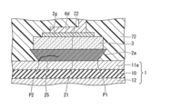
- FIG. 3 is a cross-sectional view of the semiconductor chip 3 cut diagonally as viewed from the A-A direction in FIG. 2.
- the sintered bonding layer 2a has a cross-sectional shape that is approximately trapezoidal (tapered or inverted fillet shape) in which the top base of the upper surface side (semiconductor chip 3 side) is longer than the bottom base of the lower surface side (conductive plate 11a side).
- FIG. 3 illustrates a case in which the side of the sintered bonding layer 2a is straight, but the side of the sintered bonding layer 2a may be a curved surface that is convex outward or inward.
- the surface of the sintered bonding layer 2a on the conductive plate 11a side may be a curved surface that is convex toward the conductive plate 11a side on the surface outside the outer edge of the bonding interface 21 between the sintered bonding layer 2a and the conductive plate 11a.
- the outer edge of the bonding interface 21 between the sintered bonding layer 2a and the conductive plate 11a is a triple point where the sintered bonding layer 2a, the conductive plate 11a, and the primer layer 71 come into contact.
- the width W1 of the bonding interface 21 between the sintered bonding layer 2a and the conductive plate 11a is narrower than the width W2 of the bonding interface 22 between the sintered bonding layer 2a and the semiconductor chip 3.
- the outer edge of the bonding interface 22 between the sintered bonding layer 2a and the semiconductor chip 3 coincides with the outer periphery of the semiconductor chip 3.
- the outer edge of the bonding interface 21 between the sintered bonding layer 2a and the conductive plate 11a is diagrammatically shown by a dashed line.
- the outer edge of the bonding interface 21 between the sintered bonding layer 2a and the conductive plate 11a is located inside the outer periphery of the semiconductor chip 3 and inside the outer edge of the bonding interface 22 between the sintered bonding layer 2a and the semiconductor chip 3.
- stress concentration points P1 and P2 are formed at the outer edge of the bonding interface 21 between the sintered bonding layer 2a and the conductive plate 11a. Cracks are likely to occur starting from these stress concentration points P1 and P2, and the cracks that occur gradually progress toward the center of the sintered bonding layer 2a, increasing the thermal resistance and destroying the semiconductor device.
- the stress concentration points P1 and P2 correspond to the outer edge (shown by dashed lines) of the bonding interface 21 between the sintered bonding layer 2a and the conductive plate 11a, and cracks are particularly likely to occur from the four corners of the rectangular pattern formed by the bonding interface 21.
- the outer edge of the bonding interface 21 between the sintered bonding layer 2a and the conductive plate 11a is positioned inside the outer periphery of the semiconductor chip 3 and inside the outer edge of the bonding interface 22 between the sintered bonding layer 2a and the semiconductor chip 3, so that stress concentration areas P1 and P2 are formed on the outer edge of the bonding interface 21, and cracks are actively generated starting from the stress concentration areas P1 and P2.
- the distance D1 between the outer edge of the bonding interface 21 between the sintered bonding layer 2a and the conductive plate 11a and the outer edge of the bonding interface 22 between the sintered bonding layer 2a and the semiconductor chip 3 is, for example, 5 ⁇ m or more and 50 ⁇ m or less, but is not limited to this.
- the thickness T1 of the sintered bonding layer 2a is, for example, 10 ⁇ m or more and 50 ⁇ m or less, but is not limited to this.
- the distance D1 is approximately 1/2500 to 1/50 of the length of the diagonal of the planar pattern of the semiconductor chip 3, and approximately 1/1250 to 1/50 of the thickness T1 of the sintered bonding layer 2a, but can be adjusted appropriately depending on the type of sintered bonding layer 2a, the thickness T1 of the sintered bonding layer 2a, the size of the semiconductor chip 3, etc., and is not limited to this.
- the outer edge of the upper surface side (semiconductor chip 3 side) of the sintered bonding layer 2a protrudes outward from the outer periphery of the semiconductor chip 3 by a distance D2.
- the distance D2 is, for example, about 1 ⁇ m or more and 30 ⁇ m or less, but is not limited to this.
- the part of the sintered bonding layer 2a protruding outward from the outer periphery of the semiconductor chip 3 may be removed by air blowing, cleaning, etc.
- the outer edge of the upper surface side (semiconductor chip 3 side) of the sintered bonding layer 2a may coincide with the outer periphery of the semiconductor chip 3, or may be located inside the outer periphery of the semiconductor chip 3.
- the sintered material constituting the sintered bonding layer 2a is porous and has gaps (holes) between the metal particles.
- the void ratio between the metal particles in the region of the sintered bonding layer 2a located inside the outer edge of the bonding interface 21 between the sintered bonding layer 2a and the conductive plate 11a is higher than the void ratio between the metal particles in the region of the sintered bonding layer 2a located inside the outer edge of the bonding interface 22 between the sintered bonding layer 2a and the semiconductor chip 3 and outside the outer edge of the bonding interface 21 between the sintered bonding layer 2a and the conductive plate 11a.
- the part of the sintered bonding layer 2a located inside the outer edge of the bonding interface 21 between the sintered bonding layer 2a and the conductive plate 11a is more likely to crack than the part of the sintered bonding layer 2a located inside the outer edge of the bonding interface 22 between the sintered bonding layer 2a and the semiconductor chip 3 and outside the outer edge of the bonding interface 21 between the sintered bonding layer 2a and the conductive plate 11a, and furthermore, the cracks that have occurred are more likely to propagate, which can promote the destruction of the semiconductor device.
- a primer layer 71 is inserted between the sintered bonding layer 2a and the conductive plate 11a, which corresponds to the distance (D1 + D2) from the outer edge of the upper surface (semiconductor chip 3 side) of the sintered bonding layer 2a to the outer edge of the bonding interface 21.
- the primer layer 71 is inserted between the sintered bonding layer 2a and the conductive plate 11a.
- the outer peripheral surface of the portion of the primer layer 71 located on the side of the sintered bonding layer 2a is a flat surface parallel to the vertical direction.
- the thickness of the portion of the primer layer 71 located on the side of the sintered bonding layer 2a becomes thicker as it approaches the conductive plate 11a side.
- the outer peripheral surface of the portion of the primer layer 71 located on the side of the sintered bonding layer 2a may be inclined with respect to the vertical direction or may be a curved surface.
- the thickness of the portion of the primer layer 71 located on the side of the sintered bonding layer 2a may be approximately constant, or may become thinner as it approaches the conductive plate 11a side.
- FIG. 1 illustrates an example in which a bonding wire 6b is connected to the semiconductor chip 3 as a wiring member
- FIG. 3 illustrates an example in which a lead frame 6d is connected to the semiconductor chip 3 as a wiring member.
- the lead frame 6d is connected to the semiconductor chip 3 via a bonding layer 2g.
- the bonding layer 2g is made of, for example, a sintered material or solder.
- the bonding layer 2g may be made of the same material as the sintered bonding layer 2a, or may be made of a different material.
- a heat dissipation base 8 made of a metal such as copper (Cu) is provided on the underside of the insulating circuit board 1 via a bonding layer 2b.
- a heat dissipation fin 9 made of a metal such as copper (Cu) is provided on the underside of the heat dissipation base 8 via a bonding layer 2c.
- the bonding layers 2b and 2c are made of, for example, a sintered material, solder, or a thermal interface material (TIM).
- a thermally conductive material such as thermally conductive grease, elastomer sheet, room temperature vulcanization (RTV) rubber, gel, phase change material, or silver solder can be used.
- the bonding layers 2b and 2c may be made of the same material as the sintered bonding layer 2a, or may be made of a different material.
- FIG. 4 is a cross-sectional image of a portion of the semiconductor device according to the first embodiment.
- a primer layer 71 is provided between the sintered bonding layer 2a and the sealing resin 72.
- the sealing resin 72 contains a resin base 72a and an inorganic filler 72b.
- the primer layer 71 penetrates between the sintered bonding layer 2a and the conductive plate 11a.
- the semiconductor device according to the first comparative example differs from the configuration of the semiconductor device according to the first embodiment shown in Fig. 3 in that the outer periphery of the lower surface of the sintered bonding layer 2d is located outside the outer periphery of the semiconductor chip 3, the sintered bonding layer 2d contacts the lower part of the side surface of the semiconductor chip 3, the side surface of the sintered bonding layer 2d has a shape that widens toward the end (fillet shape), there is no primer layer 71 between the sintered bonding layer 2d and the sealing resin 72, and the sealing resin 72 is made of gel.
- the semiconductor device according to the first comparative example uses the sintered bonding layer 2d, so it has a longer life than a device made of solder.
- the sintered bonding layer 2d has high heat resistance and high reliability, it is not a limiting part of the life, and the semiconductor device may be suddenly destroyed due to cracks in the semiconductor chip 3 or the insulating circuit board 1 other than the sintered bonding layer 2d. Therefore, the semiconductor device according to the first comparative example has a variable life and is prone to serious failures. Therefore, the failure mode is preferably such that the deterioration (cracks) of the bonding layer gradually progresses, as in the case of conventional solder, and the semiconductor device is destroyed due to an increase in thermal resistance, etc.
- the sealing resin 72 is made of gel.
- the semiconductor device according to the second comparative example differs from the configuration of the semiconductor device according to the first embodiment shown in FIG. 3 in that the outer periphery of the lower surface of the sintered bonding layer 2d is located outside the outer periphery of the semiconductor chip 3, the sintered bonding layer 2d contacts the lower part of the side surface of the semiconductor chip 3, and the side surface of the sintered bonding layer 2d has a flared shape (fillet shape).
- the semiconductor device according to the second comparative example also has a variable lifespan because it is not destroyed by the sintered bonding layer 2d.
- the semiconductor device according to the third comparative example differs from the configuration of the semiconductor device according to the first embodiment shown in FIG. 3 in that the outer periphery of the lower surface of the sintered bonding layer 2d is located outside the outer periphery of the semiconductor chip 3, the sintered bonding layer 2d contacts the lower part of the side surface of the semiconductor chip 3, the side surface of the sintered bonding layer 2d has a shape that widens toward the end (fillet shape), and there is no primer layer 71 between the sintered bonding layer 2d and the sealing resin 72.
- the adhesion between the sealing resin 72 and the sintered bonding layer 2d is low, so peeling occurs at the interface between the sealing resin 72 and the sintered bonding layer 2d, forming a gap 73.
- Cracks 25 occur only at the location where peeling occurs, causing destruction, but the location where peeling occurs varies, and the location where the cracks 25 occur varies, resulting in a variable lifespan.
- the semiconductor device according to the fourth comparative example differs from the configuration of the semiconductor device according to the first embodiment shown in FIG. 3 in that there is no primer layer 71 between the sintered bonding layer 2a and the sealing resin 72.
- the adhesion between the sealing resin 72 and the sintered bonding layer 2a is low, so peeling occurs at the interface between the sealing resin 72 and the sintered bonding layer 2a, forming a gap 73. Cracks 25 occur only at the locations where peeling occurs, causing destruction, but the locations where peeling occurs vary, and the locations where cracks 25 occur vary, resulting in a variable lifespan.
- the semiconductor device according to the fifth comparative example differs from the configuration of the semiconductor device according to the first embodiment shown in FIG. 3 in that there is no primer layer 71 between the sintered bonding layer 2a and the sealing resin 72, and that the sealing resin 72 is made of gel.
- the sealing resin 72 is made of gel, it is difficult to achieve high heat resistance.
- the semiconductor device according to the first embodiment has a shape (inverse fillet shape) in which the outer edge of the bonding interface 21 between the sintered bonding layer 2a and the conductive plate 11a is located inside the outer periphery of the semiconductor chip 3 and inside the outer edge of the bonding interface 22 between the sintered bonding layer 2a and the semiconductor chip 3, as shown in FIG. 3.
- a shape inverse fillet shape
- the outer edge of the bonding interface 21 between the sintered bonding layer 2a and the conductive plate 11a is located inside the outer periphery of the semiconductor chip 3 and inside the outer edge of the bonding interface 22 between the sintered bonding layer 2a and the semiconductor chip 3, as shown in FIG. 3.
- cracks 25 are actively generated starting from the stress concentration parts P1 and P2 of the sintered bonding layer 2a, and the lifespan can be determined by the sintered bonding layer 2a. Therefore, although the lifespan is shorter than that of the semiconductor devices according to the first and second comparative examples, it is possible to prevent variation in the lifespan of the semiconductor
- the semiconductor device according to the first embodiment has a primer layer 71 provided between the sintered bonding layer 2a and the sealing resin 72, thereby ensuring adhesion between the sintered bonding layer 2a and the sealing resin 72. This makes it possible to prevent peeling at the interface between the sintered bonding layer 2a and the sealing resin 72, thereby reducing variation in lifespan and stabilizing lifespan.
- the semiconductor device according to the first embodiment has sealing resin 72 made of a thermosetting resin such as epoxy resin, which makes it possible to achieve higher heat resistance than when sealing resin 72 is made of a gel.
- the distance between the sintered bonding layer 2a and the sealing resin 72 becomes smaller as one approaches the outer edge of the bonding interface 21, so that the inorganic filler contained in the sealing resin 72 has difficulty penetrating between the sintered bonding layer 2a and the sealing resin 72, and a gap may be formed between the sintered bonding layer 2a and the sealing resin 72.
- the primer layer 71 easily penetrates between the sintered bonding layer 2a and the sealing resin 72, so that the gap between the sintered bonding layer 2a and the sealing resin 72 can be easily filled.
- the width W2 of the bonding interface 22 between the sintered bonding layer 2a and the semiconductor chip 3 is wider than the width W1 of the outer edge of the bonding interface 21 between the sintered bonding layer 2a and the conductive plate 11a, so that heat from the semiconductor chip 3 can be dissipated efficiently and damage to the end of the semiconductor chip 3 can be prevented.
- FIG. 11 shows the results of a reliability test (power cycle test) for the semiconductor device according to the first embodiment (Example) shown in FIG. 3, the semiconductor device according to the first comparative example shown in FIG. 5, the semiconductor device according to the second comparative example shown in FIG. 6, the semiconductor device according to the third comparative example shown in FIG. 7, the semiconductor device according to the fourth comparative example shown in FIG. 8, and the semiconductor device according to the fifth comparative example shown in FIG. 9.
- the breakage did not occur in the sintered bonding layer 2d, but occurred in a location other than the sintered bonding layer 2d.
- a method for manufacturing (assembling) the semiconductor device according to the first embodiment will be described.
- a rubber sheet 32 is placed on the upper surface of a base 31, and a sintered sheet 2, which is a sheet-like sintered material, is placed on the upper surface of the rubber sheet 32.
- a semiconductor chip 3 is sucked by a suction portion 34 of a mounter head 33, and the lower surface of the semiconductor chip 3 is opposed to the upper surface of the sintered sheet 2.
- the mounter head 33 is lowered to press the underside of the semiconductor chip 3 against the sintered sheet 2.
- stress is concentrated at the ends of the underside of the semiconductor chip 3, compressing the sintered sheet 2 at the ends of the underside of the semiconductor chip 3, making it thinner than the sintered sheet 2 at the center of the underside of the semiconductor chip 3.
- the porosity of the relatively thin parts at the ends of the sintered sheet 2 is lower than the porosity of the relatively thick part at the center of the sintered sheet 2. Note that when pressing the underside of the semiconductor chip 3 against the sintered sheet 2, heating and pressure may be applied to make it easier to transfer the sintered sheet 2.
- the mounter head 33 is raised to cut out a portion of the sintered sheet 2, and the sintered bonding layer 2a made of a portion of the sintered sheet 2 is transferred to the underside of the semiconductor chip 3.
- the sintered bonding layer 2a is relatively thick at the center and relatively thin at the ends.
- an insulating circuit board 1 is prepared as shown in FIG. 15.
- the conductive plate 11b shown in FIG. 1 is omitted.
- multiple semiconductor chips 3, each having a sintered bonding layer 2a formed thereon are mounted on the conductive plate 11a of the insulating circuit board 1.
- FIG. 15 shows multiple semiconductor chips 3, each having a sintered bonding layer 2a formed thereon, it is also possible to mount only one semiconductor chip 3 having a sintered bonding layer 2a formed thereon, as shown in FIG. 1.
- pressure is applied from the top side of the semiconductor chip 3 by a pressure unit 41 made of silicon (Si) rubber or the like attached to a mold 42 of a press machine.
- the semiconductor chip 3 is heated in a pressurized state, causing a sintering reaction in the sintered bonding layer 2a.
- the pressure is set to about 1 MPa or more and 60 MPa or less
- the heating temperature is set to about 150°C or more and 350°C or less
- the heating time is set to about 1 minute or more and 5 minutes or less.
- a case 5 is placed around the insulating circuit board 1 and the semiconductor chip 3, and the insulating circuit board 1, the semiconductor chip 3, and the external terminals 4a, 4b are connected by wiring members such as bonding wires 6a, 6b, 6c (see FIG. 1).
- a primer layer 71 is formed so as to cover the surfaces of the sintered bonding layer 2a and the semiconductor chip 3 by a method such as spray coating, dipping, or coating with a dispenser (see FIG. 1). Thereafter, the surface of the primer layer 71 is covered and sealed with sealing resin 72, thereby completing the semiconductor device according to the first embodiment shown in FIG. 1.
- the method for manufacturing a semiconductor device according to the first embodiment makes it possible to realize a semiconductor device that is highly heat resistant and can reduce or prevent variations in lifespan due to peeling at the interface between the sintered bonding layer 2a and the sealing resin 72.
- a paste-like sintered bonding layer 2a may be applied to the underside of the semiconductor chip 3 by screen printing or the like so that the central side is relatively thick and the end sides are relatively thin.
- a rubber sheet 32 is placed on the upper surface of the base 31, but a recess may be provided in the base 31 without using the rubber sheet 32.
- a sintered bonding layer 2a that is relatively thick at the center and relatively thin at the ends can be transferred.
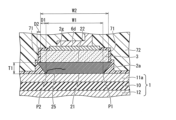
- the semiconductor device according to the second embodiment differs from the semiconductor device according to the first embodiment shown in FIG. 3 in that a primer layer 71 and a sealing resin 72 are inserted between the sintered bonding layer 2a and the conductive plate 11a.
- the primer layer 71 is provided with a substantially constant thickness along the side surface of the sintered bonding layer 2a.
- the shape of the primer layer 71 can be appropriately adjusted by the viscosity and application amount of the primer layer 71.
- the other configurations of the semiconductor device according to the second embodiment are the same as those of the semiconductor device according to the first embodiment, so that the overlapping description will be omitted.
- the semiconductor device according to the second embodiment can be realized by the same procedure as the manufacturing method of the semiconductor device according to the first embodiment.
- cracks can be actively generated starting from the stress concentration points P1 and P2 of the sintered bonding layer 2a to intentionally destroy the semiconductor device, thereby preventing variations in the life span of the semiconductor device. Furthermore, by providing a primer layer 71 between the sintered bonding layer 2a and the sealing resin 72, the life span variations due to peeling of the sealing resin 72 can be reduced. Furthermore, since the width W2 of the bonding interface 22 between the sintered bonding layer 2a and the semiconductor chip 3 is wider than the width W1 of the outer edge of the bonding interface 21 between the sintered bonding layer 2a and the conductive plate 11a, heat from the semiconductor chip 3 can be efficiently dissipated and damage to the end of the semiconductor chip 3 can be prevented.
- the semiconductor device according to the third embodiment has the same configuration as the semiconductor device according to the first embodiment shown in Fig. 3 in that the outer edge of the bonding interface 21 between the sintered bonding layer 2a and the conductive plate 11a is located inside the outer periphery of the semiconductor chip 3 and inside the outer edge of the bonding interface 22 between the sintered bonding layer 2a and the semiconductor chip 3.
- the semiconductor device according to the third embodiment differs from the configuration of the semiconductor device according to the first embodiment in that the outer edge of the upper surface side (semiconductor chip 3 side) of the sintered bonding layer 2a coincides with the outer periphery of the semiconductor chip 3 and coincides with the outer edge of the bonding interface 22 between the sintered bonding layer 2a and the semiconductor chip 3.
- the rest of the configuration of the semiconductor device according to the third embodiment is similar to that of the semiconductor device according to the first embodiment, so duplicated explanations will be omitted.
- the semiconductor device according to the third embodiment can be realized by a procedure similar to that of the manufacturing method of the semiconductor device according to the first embodiment.
- cracks can be actively generated starting from the stress concentration points P1 and P2 of the sintered bonding layer 2a to intentionally destroy the semiconductor device, thereby preventing variations in the life span of the semiconductor device. Furthermore, by providing a primer layer 71 between the sintered bonding layer 2a and the sealing resin 72, the variation in life span caused by peeling of the sealing resin 72 can be reduced. Furthermore, since the outer edge of the bonding interface 22 between the sintered bonding layer 2a and the semiconductor chip 3 coincides with the outer periphery of the semiconductor chip 3, it is possible to prevent the portion of the sintered bonding layer 2a that protrudes outward beyond the outer periphery of the semiconductor chip 3 from falling off.
- the semiconductor device according to the fourth embodiment differs from the semiconductor device according to the third embodiment shown in FIG. 18 in that a primer layer 71 and a sealing resin 72 are inserted between the sintered bonding layer 2a and the conductive plate 11a.
- the primer layer 71 is provided with a substantially constant thickness along the side surface of the sintered bonding layer 2a.
- the shape of the primer layer 71 can be appropriately adjusted by the viscosity and application amount of the primer layer 71.
- the other configurations of the semiconductor device according to the fourth embodiment are the same as those of the semiconductor device according to the third embodiment, so that the overlapping description will be omitted.
- the semiconductor device according to the fourth embodiment can be realized by the same procedure as the manufacturing method of the semiconductor device according to the third embodiment.
- cracks can be actively generated starting from the stress concentration points P1 and P2 of the sintered bonding layer 2a to intentionally destroy the semiconductor device, thereby preventing variations in the lifespan of the semiconductor device. Furthermore, by providing a primer layer 71 between the sintered bonding layer 2a and the sealing resin 72, the variation in lifespan caused by peeling of the sealing resin 72 can be reduced. Furthermore, since the outer edge of the bonding interface 22 between the sintered bonding layer 2a and the semiconductor chip 3 coincides with the outer periphery of the semiconductor chip 3, it is possible to prevent the part of the sintered bonding layer 2a that protrudes outward beyond the outer periphery of the semiconductor chip 3 from falling off.
- the semiconductor device according to the fifth embodiment is similar to the semiconductor device according to the first embodiment shown in FIG. 3 in that the outer edge of the bonding interface 21 between the sintered bonding layer 2a and the conductive plate 11a is located inside the outer periphery of the semiconductor chip 3 and inside the outer edge of the bonding interface 22 between the sintered bonding layer 2a and the semiconductor chip 3.
- the semiconductor device according to the fifth embodiment is different from the semiconductor device according to the first embodiment in that the outer edge of the upper surface side (semiconductor chip 3 side) of the sintered bonding layer 2a is located inside the outer periphery of the semiconductor chip 3 and coincides with the outer edge of the bonding interface 22 between the sintered bonding layer 2a and the semiconductor chip 3.
- the rest of the configuration of the semiconductor device according to the fifth embodiment is similar to that of the semiconductor device according to the first embodiment, so duplicated explanations will be omitted.
- the semiconductor device according to the fifth embodiment can be realized by a procedure similar to that of the manufacturing method of the semiconductor device according to the first embodiment.
- cracks can be actively generated starting from the stress concentration points P1 and P2 of the sintered bonding layer 2a to intentionally destroy the semiconductor device, thereby preventing variations in the lifespan of the semiconductor device. Furthermore, by providing a primer layer 71 between the sintered bonding layer 2a and the sealing resin 72, the variation in lifespan caused by peeling of the sealing resin 72 can be reduced. Furthermore, since the outer edge of the bonding interface 22 between the sintered bonding layer 2a and the semiconductor chip 3 is located inside the outer periphery of the semiconductor chip 3, it is possible to prevent the protruding portion of the sintered bonding layer 2a from falling off when it protrudes outside the outer periphery of the semiconductor chip 3.
- the semiconductor device according to the sixth embodiment differs from the semiconductor device according to the fifth embodiment shown in FIG. 20 in that a primer layer 71 and a sealing resin 72 are inserted between the sintered bonding layer 2a and the conductive plate 11a, as shown in FIG. 21.
- the primer layer 71 is provided with a substantially constant thickness along the side surface of the sintered bonding layer 2a.
- the shape of the primer layer 71 can be appropriately adjusted by the viscosity and application amount of the primer layer 71.
- the other configurations of the semiconductor device according to the sixth embodiment are the same as those of the semiconductor device according to the fifth embodiment, so that the overlapping description will be omitted.
- the semiconductor device according to the sixth embodiment can be realized by the same procedure as the manufacturing method of the semiconductor device according to the fifth embodiment.
- cracks can be actively generated starting from the stress concentration points P1 and P2 of the sintered bonding layer 2a to intentionally destroy the semiconductor device, thereby preventing variations in the life span of the semiconductor device. Furthermore, by providing a primer layer 71 between the sintered bonding layer 2a and the sealing resin 72, the variation in life span caused by peeling of the sealing resin 72 can be reduced. Furthermore, since the outer edge of the bonding interface 22 between the sintered bonding layer 2a and the semiconductor chip 3 is located inside the outer periphery of the semiconductor chip 3, it is possible to prevent the protruding portion of the sintered bonding layer 2a from falling off when it protrudes outside the outer periphery of the semiconductor chip 3.
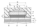
- the semiconductor device according to the seventh embodiment is similar to the semiconductor device according to the first embodiment shown in Fig. 3 in that the outer edge of the bonding interface 23 between the sintered bonding layer (2e, 2f) and the conductive plate 11a is located inside the outer periphery of the semiconductor chip 3 and inside the outer edge of the bonding interface 24 between the semiconductor chip 3 and the sintered bonding layer (2e, 2f).
- the semiconductor device according to the seventh embodiment is different from the semiconductor device according to the first embodiment in that the sintered bonding layer (2e, 2f) is configured as a two-layer structure having a first bonding layer (lower bonding layer) 2e that bonds with the conductive plate 11a and a second bonding layer (upper bonding layer) 2f that bonds the lower bonding layer 2e with the semiconductor chip 3.
- the sintered bonding layer (2e, 2f) is configured as a two-layer structure having a first bonding layer (lower bonding layer) 2e that bonds with the conductive plate 11a and a second bonding layer (upper bonding layer) 2f that bonds the lower bonding layer 2e with the semiconductor chip 3.
- the lower bonding layer 2e and the upper bonding layer 2f are each composed of a sintered material in a paste or sheet form, similar to the sintered bonding layer 2a of the semiconductor device according to the first embodiment.
- the lower bonding layer 2e and the upper bonding layer 2f may be composed of the same material or different materials.
- the thickness of the lower bonding layer 2e may be the same as the thickness of the upper bonding layer 2f, may be thinner than the thickness of the upper bonding layer 2f, or may be thicker than the thickness of the upper bonding layer 2f.
- the outer edge of the bonding interface 23 between the lower bonding layer 2e and the conductive plate 11a is located inside the outer edge of the bonding interface 24 between the semiconductor chip 3 and the upper bonding layer 2f. Therefore, stress concentration portions P3 and P4 are formed at the outer edge of the bonding interface 23 between the lower bonding layer 2e and the conductive plate 11a.
- the other configuration of the semiconductor device according to the seventh embodiment is similar to that of the semiconductor device according to the first embodiment, so a duplicated description will be omitted.
- cracks can be actively generated starting from the stress concentration points P3, P4 of the lower bonding layer 2e of the sintered bonding layer (2e, 2f) to intentionally destroy the semiconductor device, thereby preventing variation in the lifespan of the semiconductor device. Furthermore, by providing a primer layer 71 between the sintered bonding layer (2e, 2f) and the sealing resin 72, variation in the lifespan caused by peeling of the sealing resin 72 can be reduced.
- a paste-like upper bonding layer 2f is applied evenly to the underside of the semiconductor chip 3 by screen printing or the like, and then the upper bonding layer 2f is dried.
- the upper bonding layer 2f may be formed evenly on the underside of the semiconductor chip 3 by transferring a sintered sheet.
- the upper bonding layer 2f may also be formed in advance on the underside of the semiconductor wafer before the semiconductor wafer is diced to form the semiconductor chips 3.
- a paste-like lower bonding layer 2e is applied to the upper surface of the conductive plate 11a of the insulating circuit board 1 by screen printing or the like, with an area smaller than that of the upper bonding layer 2f, and then the lower bonding layer 2e is dried.
- the lower bonding layer 2e made of a sintered sheet may be mounted on the upper surface of the conductive plate 11a of the insulating circuit board 1.
- the upper bonding layer 2f formed on the underside of the semiconductor chip 3 shown in FIG. 23 and the lower bonding layer 2e formed on the upper surface of the insulating circuit board 1 are bonded together, and pressure and heat are applied to bond the insulating circuit board 1 and the semiconductor chip 3 via the sintered bonding layers (2e, 2f).
- the other steps of the manufacturing method for the semiconductor device according to the seventh embodiment are the same as those of the manufacturing method for the semiconductor device according to the first embodiment, so duplicated explanations will be omitted.
- the sintered bonding layer (2e, 2f) is illustrated as having a two-layer structure with a lower bonding layer 2e and an upper bonding layer 2f, but the bonding layer may be a laminated structure of three or more layers of sintered material.
- the bonding layer has a three-layer structure, after forming the lower bonding layer 2e on the upper surface of the conductive plate 11a of the insulating circuit board 1, a third bonding layer (intermediate bonding layer) having an area larger than that of the lower bonding layer 2e and smaller than that of the upper bonding layer 2f may be formed on the upper surface of the lower bonding layer 2e.
- the semiconductor device according to the seventh embodiment a configuration has been exemplified in which the outer periphery of the upper bonding layer 2f coincides with the outer periphery of the semiconductor chip 3 and coincides with the outer edge of the bonding interface 24 between the semiconductor chip 3 and the upper bonding layer 2f, but the outer periphery of the upper bonding layer 2f may be located inside the outer periphery of the semiconductor chip 3 and coincide with the outer edge of the bonding interface 24 between the semiconductor chip 3 and the upper bonding layer 2f.
- the outer periphery of the upper bonding layer 2f coincides with the outer periphery of the semiconductor chip 3
- the outer periphery of the upper bonding layer 2f may protrude outward from the outer periphery of the semiconductor chip 3.
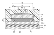
- the semiconductor device according to the eighth embodiment is different from the semiconductor device according to the seventh embodiment shown in FIG. 22 in that a primer layer 71 and a sealing resin 72 are inserted between the sintered bonding layer (2e, 2f) and the conductive plate 11a.
- the primer layer 71 is provided with a substantially constant thickness along the side of the sintered bonding layer (2e, 2f).
- the shape of the primer layer 71 can be appropriately adjusted by the viscosity of the primer layer 71, the amount of application, etc.
- the other configurations of the semiconductor device according to the eighth embodiment are the same as those of the semiconductor device according to the seventh embodiment, so that the overlapping description will be omitted.
- the semiconductor device according to the eighth embodiment can be realized by the same procedure as the manufacturing method of the semiconductor device according to the seventh embodiment.
- cracks can be actively generated starting from the stress concentration points P3, P4 of the lower bonding layer 2e of the sintered bonding layer (2e, 2f) to intentionally destroy the semiconductor device, thereby preventing variation in the lifespan of the semiconductor device. Furthermore, by providing a primer layer 71 between the sintered bonding layer (2e, 2f) and the sealing resin 72, variation in the lifespan due to peeling of the sealing resin 72 can be reduced.
- the semiconductor device according to the first to eighth embodiments is exemplified as a configuration in which the semiconductor chip 3 is connected via the bonding wires 6a, 6b, 6c or the lead frame 6d, which are wiring members, but the present invention is not limited to this.
- the present invention can also be applied to a semiconductor device configured such that an implant substrate having pin-shaped post electrodes inserted into a printed circuit board is provided above the semiconductor chip 3, and the semiconductor chip 3 is connected to the post electrodes.
Landscapes
- Structures Or Materials For Encapsulating Or Coating Semiconductor Devices Or Solid State Devices (AREA)
- Die Bonding (AREA)
Priority Applications (3)
| Application Number | Priority Date | Filing Date | Title |
|---|---|---|---|
| DE112024000132.7T DE112024000132T5 (de) | 2023-04-13 | 2024-03-04 | Halbleitervorrichtung |
| JP2025513823A JPWO2024214425A1 (https=) | 2023-04-13 | 2024-03-04 | |
| US19/093,969 US20250226276A1 (en) | 2023-04-13 | 2025-03-28 | Semiconductor device |
Applications Claiming Priority (2)
| Application Number | Priority Date | Filing Date | Title |
|---|---|---|---|
| JP2023-065562 | 2023-04-13 | ||
| JP2023065562 | 2023-04-13 |
Related Child Applications (1)
| Application Number | Title | Priority Date | Filing Date |
|---|---|---|---|
| US19/093,969 Continuation US20250226276A1 (en) | 2023-04-13 | 2025-03-28 | Semiconductor device |
Publications (1)
| Publication Number | Publication Date |
|---|---|
| WO2024214425A1 true WO2024214425A1 (ja) | 2024-10-17 |
Family
ID=93059480
Family Applications (1)
| Application Number | Title | Priority Date | Filing Date |
|---|---|---|---|
| PCT/JP2024/008106 Ceased WO2024214425A1 (ja) | 2023-04-13 | 2024-03-04 | 半導体装置 |
Country Status (4)
| Country | Link |
|---|---|
| US (1) | US20250226276A1 (https=) |
| JP (1) | JPWO2024214425A1 (https=) |
| DE (1) | DE112024000132T5 (https=) |
| WO (1) | WO2024214425A1 (https=) |
Citations (6)
| Publication number | Priority date | Publication date | Assignee | Title |
|---|---|---|---|---|
| JP2006032617A (ja) * | 2004-07-15 | 2006-02-02 | Hitachi Ltd | 半導体パワーモジュール |
| JP2013062439A (ja) * | 2011-09-14 | 2013-04-04 | Toyota Motor Corp | パワーモジュールおよびその製造方法 |
| JP2015164165A (ja) * | 2014-01-30 | 2015-09-10 | 日立化成株式会社 | 半導体装置 |
| JP2021150458A (ja) * | 2020-03-18 | 2021-09-27 | 富士電機株式会社 | 半導体装置 |
| JP2022158353A (ja) * | 2021-04-01 | 2022-10-17 | 富士電機株式会社 | 半導体モジュールおよび半導体モジュールの製造方法 |
| WO2023286432A1 (ja) * | 2021-07-16 | 2023-01-19 | 富士電機株式会社 | 半導体装置 |
-
2024
- 2024-03-04 DE DE112024000132.7T patent/DE112024000132T5/de active Pending
- 2024-03-04 WO PCT/JP2024/008106 patent/WO2024214425A1/ja not_active Ceased
- 2024-03-04 JP JP2025513823A patent/JPWO2024214425A1/ja active Pending
-
2025
- 2025-03-28 US US19/093,969 patent/US20250226276A1/en active Pending
Patent Citations (6)
| Publication number | Priority date | Publication date | Assignee | Title |
|---|---|---|---|---|
| JP2006032617A (ja) * | 2004-07-15 | 2006-02-02 | Hitachi Ltd | 半導体パワーモジュール |
| JP2013062439A (ja) * | 2011-09-14 | 2013-04-04 | Toyota Motor Corp | パワーモジュールおよびその製造方法 |
| JP2015164165A (ja) * | 2014-01-30 | 2015-09-10 | 日立化成株式会社 | 半導体装置 |
| JP2021150458A (ja) * | 2020-03-18 | 2021-09-27 | 富士電機株式会社 | 半導体装置 |
| JP2022158353A (ja) * | 2021-04-01 | 2022-10-17 | 富士電機株式会社 | 半導体モジュールおよび半導体モジュールの製造方法 |
| WO2023286432A1 (ja) * | 2021-07-16 | 2023-01-19 | 富士電機株式会社 | 半導体装置 |
Also Published As
| Publication number | Publication date |
|---|---|
| US20250226276A1 (en) | 2025-07-10 |
| JPWO2024214425A1 (https=) | 2024-10-17 |
| DE112024000132T5 (de) | 2025-05-15 |
Similar Documents
| Publication | Publication Date | Title |
|---|---|---|
| JP7532933B2 (ja) | 半導体装置及びその製造方法 | |
| JP6755386B2 (ja) | 電力用半導体モジュールおよび電力用半導体モジュールの製造方法 | |
| US5644163A (en) | Semiconductor device | |
| CN104517909B (zh) | 带有印制电路板的半导体模块及其制造方法 | |
| JP7758115B2 (ja) | 半導体装置の製造方法 | |
| CN113206048A (zh) | 半导体装置及其制造方法 | |
| CN112530915B (zh) | 半导体装置 | |
| CN114078790A (zh) | 功率半导体模块装置及其制造方法 | |
| JP7513212B2 (ja) | 半導体装置 | |
| CN111834307B (zh) | 半导体模块 | |
| CN117043931A (zh) | 电源模块及其制造方法 | |
| WO2024214425A1 (ja) | 半導体装置 | |
| JP7552917B2 (ja) | 半導体装置及びその製造方法 | |
| US20230154882A1 (en) | Semiconductor device and method for manufacturing the same | |
| JP5004837B2 (ja) | 構造体及び電子装置 | |
| US20250006622A1 (en) | Semiconductor module and manufacturing method thereof | |
| US20250233107A1 (en) | Semiconductor device and method of manufacturing the same | |
| JP7459395B1 (ja) | 半導体装置 | |
| JP7570298B2 (ja) | 半導体装置 | |
| KR102588851B1 (ko) | 파워모듈 및 그 제조방법 | |
| WO2024236885A1 (ja) | 半導体装置 | |
| JP6777440B2 (ja) | 回路基板および電子装置 | |
| JP2025026715A (ja) | 半導体装置 | |
| CN119790497A (zh) | 半导体装置及半导体装置的制造方法 | |
| JP2021044311A (ja) | パワーモジュール |
Legal Events
| Date | Code | Title | Description |
|---|---|---|---|
| 121 | Ep: the epo has been informed by wipo that ep was designated in this application |
Ref document number: 24788455 Country of ref document: EP Kind code of ref document: A1 |
|
| WWE | Wipo information: entry into national phase |
Ref document number: 112024000132 Country of ref document: DE |
|
| WWE | Wipo information: entry into national phase |
Ref document number: 2025513823 Country of ref document: JP |
|
| WWP | Wipo information: published in national office |
Ref document number: 112024000132 Country of ref document: DE |
|
| 122 | Ep: pct application non-entry in european phase |
Ref document number: 24788455 Country of ref document: EP Kind code of ref document: A1 |