WO2024209891A1 - コネクタ - Google Patents
コネクタ Download PDFInfo
- Publication number
- WO2024209891A1 WO2024209891A1 PCT/JP2024/009589 JP2024009589W WO2024209891A1 WO 2024209891 A1 WO2024209891 A1 WO 2024209891A1 JP 2024009589 W JP2024009589 W JP 2024009589W WO 2024209891 A1 WO2024209891 A1 WO 2024209891A1
- Authority
- WO
- WIPO (PCT)
- Prior art keywords
- slits
- connector
- connection
- slit
- signal terminals
- Prior art date
- Legal status (The legal status is an assumption and is not a legal conclusion. Google has not performed a legal analysis and makes no representation as to the accuracy of the status listed.)
- Ceased
Links
Images








Classifications
-
- H—ELECTRICITY
- H01—ELECTRIC ELEMENTS
- H01R—ELECTRICALLY-CONDUCTIVE CONNECTIONS; STRUCTURAL ASSOCIATIONS OF A PLURALITY OF MUTUALLY-INSULATED ELECTRICAL CONNECTING ELEMENTS; COUPLING DEVICES; CURRENT COLLECTORS
- H01R12/00—Structural associations of a plurality of mutually-insulated electrical connecting elements, specially adapted for printed circuits, e.g. printed circuit boards [PCB], flat or ribbon cables, or like generally planar structures, e.g. terminal strips, terminal blocks; Coupling devices specially adapted for printed circuits, flat or ribbon cables, or like generally planar structures; Terminals specially adapted for contact with, or insertion into, printed circuits, flat or ribbon cables, or like generally planar structures
- H01R12/70—Coupling devices
- H01R12/71—Coupling devices for rigid printing circuits or like structures
Definitions
- a known example of a conventional connector-related invention is the surface-mount connector device described in Patent Document 1.
- the surface-mount connector device described in Patent Document 1 is mounted on a printed circuit board. Pads are formed on the surface of the printed circuit board.
- the surface-mount connector device described in Patent Document 1 is connected to a mating connector device.
- the surface-mount connector device described in Patent Document 1 includes a connector body, contacts fixed to the connector body, and leads soldered to the pads and connected to the contacts.
- the connector body is made of resin.
- the printed circuit board mounting side of the connector body has multiple parallel slits.
- the mating connector side of the connector body has multiple parallel slits. Each of the multiple slits has a wedge shape extending in a direction perpendicular to the longitudinal direction of the connector body.
- the surface-mount connector device described in Patent Document 1 is heated during soldering.
- the object of the present invention is to provide a connector that can suppress warping of the resin body member due to heating.
- a connector includes:
- the device includes a resin main body member, one or more cover members, and one or more external connection terminals,
- the resin body member is A first portion; and A second part; and A third part; and a first connection portion that connects the first portion and the second portion; a second connection portion connecting the second portion and the third portion;
- Contains The second portion extends in a front-rear direction, the first portion, the first connection portion, the second portion, the second connection portion, and the third portion are arranged in this order in a forward direction, the material of the cover member is metal;
- the cover member is A first cover portion that covers at least a portion of the first portion; A second cover portion that covers at least a portion of the third portion; Contains the one or more external connection terminals are supported by the second portion;
- the first connection portion is provided with one or more first slits having a linear shape extending in the vertical direction
- the second connection portion is provided with one or more second slits having a linear shape extending in the up
- FIG. 1 is a perspective view of a connector set 1 according to the first embodiment.
- FIG. 2 is a perspective view of the first connector 10 when the first connector 10 and the second connector 110 according to the first embodiment are not connected to each other.
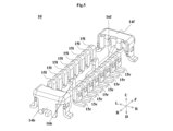
- FIG. 3 is a perspective view of the first resin body member 11 according to the first embodiment.
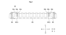
- FIG. 4 is a cross-sectional view of the first resin body member 11 according to the first embodiment viewed from the left.
- FIG. 5 is a perspective view of the first signal terminals 15l and 15r, the second signal terminals 16b and 16f, and the first ground terminals 14b and 14f according to the first preferred embodiment.
- FIG. 6 is a perspective view of the second connector 110 when the first connector 10 and the second connector 110 according to the first embodiment are not connected to each other.
- FIG. 1 is a perspective view of a connector set 1 according to the first embodiment.
- FIG. 2 is a perspective view of the first connector 10 when the first connector 10 and the second connector 110 according to the first embodiment are not connected
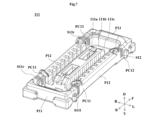
- FIG. 7 is a perspective view of the second resin body member 111 according to the first embodiment.
- FIG. 8 is a cross-sectional view of the second resin body member 111 according to the first embodiment viewed from the right.
- FIG. 9 is a perspective view of the third signal terminals 115l and 115r, the fourth signal terminals 116b and 116f, and the second ground terminal 114 according to the first embodiment.
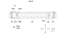
- FIG. 10 is a cross-sectional view of a first resin body member 11 according to a first modified example, viewed from the left.
- FIG. 11 is a cross-sectional view of a second resin body member 111 according to a first modified example, viewed from the right.
- FIG. 12 is a cross-sectional view of a first resin body member 11 according to a second modified example, viewed from the left.
- FIG. 13 is a cross-sectional view of a second resin body member 111 according to a second modified example, viewed from the right.
- FIG. 14 is a cross-sectional view of a first resin body member 11 according to a third modified example, viewed from the left.
- FIG. 15 is a cross-sectional view of a second resin body member 111 according to the third modified example, viewed from the right.
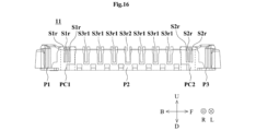
- FIG. 16 is a cross-sectional view of a first resin body member 11 according to a fourth modified example, viewed from the left.
- FIG. 17 is a cross-sectional view of a second resin body member 111 according to the fourth modified example, viewed from the right.
- FIG. 1 is a perspective view of the connector set 1 according to the first embodiment.
- directions are defined as follows.
- the direction from the second connector 110 to the first connector 10 is defined as the downward direction.
- the opposite direction of the downward direction is defined as the upward direction.
- the direction in which the first ground terminals 14b, 14f are arranged in this order in the first connector 10 is defined as the forward direction.
- the opposite direction of the forward direction is defined as the rearward direction.
- the forward or rearward direction is perpendicular to the downward or upward direction.
- the direction perpendicular to the downward and forward directions is defined as the rightward direction.
- the opposite direction of the rightward direction is defined as the leftward direction.
- the downward, upward, forward, rear, right, and left directions in this specification are directions defined for the convenience of explanation, and do not have to match the downward, upward, forward, rear, right, and left directions when the connector set 1 is in use.
- the downward and upward directions may be interchanged, the front and rear directions may be interchanged, and the right and left directions may be interchanged in each drawing.
- the positional relationship of the members is defined as follows.
- the first member to the third member constitute the connector set 1.
- a first member being positioned above a second member includes cases where at least a portion of the first member is located directly above the second member, and cases where the first member is not located directly above the second member but is located diagonally above the second member. In this case, the first member does not have to overlap with the second member when viewed from below.
- Diagonally above means, for example, top left or top right. This definition also applies to directions other than the upward direction.
- each part of the first member is defined as follows:
- the front part of the first member means the front half of the first member.
- the front end of the first member means the front end of the first member.
- the front end part of the first member means the front end of the first member and its vicinity. This definition also applies to directions other than the forward direction.
- a first member being supported by a second member includes a case in which the first member is attached to the second member so as to be immovable relative to the second member (i.e., fixed), and a case in which the first member is attached to the second member so as to be movable relative to the second member.
- a first member being supported by a second member includes both a case in which the first member is directly attached to the second member, and a case in which the first member is attached to the second member via a third member.
- a first member is held by a second member includes the case where the first member is attached to the second member (i.e., fixed) so as not to be movable relative to the second member, and does not include the case where the first member is attached to the second member so as to be movable relative to the second member.
- a first member is held by a second member includes both the case where the first member is directly attached to the second member, and the case where the first member is attached to the second member via a third member.
- the first member and the second member are electrically connected means that electricity is conducted between the first member and the second member. Therefore, the first member and the second member may be in contact with each other, or may not be in contact with each other. When the first member and the second member are not in contact with each other, a third member having electrical conductivity is disposed between the first member and the second member.
- a member extending in the vertical direction refers to a member that is inclined within a range of ⁇ 45° relative to the vertical direction.
- a member extending in the front-to-rear direction does not necessarily refer only to a member that is parallel to the front-to-rear direction.
- a member extending in the front-to-rear direction refers to a member that is inclined within a range of ⁇ 45° relative to the front-to-rear direction.
- a member extending in the left-to-right direction refers to a member that is inclined within a range of ⁇ 45° relative to the left-to-right direction.
- the connector set 1 is used, for example, to connect two circuit boards. As shown in FIG. 1, the connector set 1 includes a first connector 10 and a second connector 110. When the first connector 10 and the second connector 110 are connected, the second connector 110 is located above the first connector 10.
- FIG. 2 is a perspective view of the first connector 10 when the first connector 10 and the second connector 110 according to the first embodiment are not connected.
- Fig. 3 is a perspective view of the first resin body member 11 according to the first embodiment.
- Fig. 4 is a cross-sectional view of the first resin body member 11 according to the first embodiment viewed from the left.
- Fig. 5 is a perspective view of the first signal terminals 15l, 15r, the second signal terminals 16b, 16f, and the first ground terminals 14b, 14f according to the first embodiment. Note that in Figs.
- the first connector 10 includes a first resin body member 11, first ground terminals 14b, 14f, a plurality of first signal terminals 15l, a plurality of first signal terminals 15r, and a second signal terminals 16b, 16f.
- the first resin body member 11, the first ground terminals 14b, 14f, the plurality of first signal terminals 15l, the plurality of first signal terminals 15r, and the second signal terminals 16b, 16f are integrally molded by press-fitting.
- the first resin body member 11 corresponds to the "resin body member”.
- each of the first signal terminals 15l, 15r corresponds to the "external connection terminal”.
- the first ground terminals 14b, 14f correspond to the "cover member".
- the first ground terminal 14b corresponds to the "first cover part”.
- the first ground terminal 14f corresponds to the "second cover part”.
- the first resin body member 11 includes a bottom surface portion 11a and a frame portion 11b.
- the frame portion 11b has a ring shape when viewed in the vertical direction. More specifically, the frame portion 11b has rear and front sides extending in the left-right direction and left and right sides extending in the front-rear direction when viewed in the vertical direction.
- the bottom surface portion 11a covers the lower surface of the area surrounded by the frame portion 11b when viewed in the vertical direction.
- the material of the first resin body member 11 is an insulating material.
- the material of the first resin body member 11 is, for example, resin.
- the rear end of the first resin body member 11 is defined as the first portion P1.
- the first portion P1 includes the rear edge of the frame portion 11b, the rear end of the left side of the frame portion 11b, and the rear end of the right side of the frame portion 11b.
- the front end of the first resin body member 11 is defined as the third portion P3.
- the third portion P3 includes the front edge of the frame portion 11b, the front end of the left side of the frame portion 11b, and the front end of the right side of the frame portion 11b.
- the portion located between the first portion P1 and the third portion P3 is defined as the second portion P2.
- the second portion P2 includes a portion of the left side of the frame portion 11b and a portion of the right side of the frame portion 11b.
- the second portion P2 extends in the front-to-rear direction.
- the portion located between the first portion P1 and the second portion P2 is defined as the first connection portion PC1.
- the first connection portion PC1 includes a portion of the left side of the frame portion 11b and a portion of the right side of the frame portion 11b.
- the first connection portion PC1 connects the first portion P1 and the second portion P2.
- the portion located between the second portion P2 and the third portion P3 is defined as the second connection portion PC2.
- the second connection portion PC2 includes a portion of the left side of the frame portion 11b and a portion of the right side of the frame portion 11b.
- the second connection portion PC2 connects the second portion P2 and the third portion P3.
- the first resin body member 11 includes the first portion P1, the second portion P2, the third portion P3, the first connection portion PC1, and the second connection portion PC2.
- the first portion P1, the first connection portion PC1, the second portion P2, the second connection portion PC2, and the third portion P3 are arranged in this order in the forward direction.
- the first connection portion PC1 is provided with a plurality of first slits S1l, S1r. More specifically, the plurality of first slits S1l are provided in the left portion of the first connection portion PC1. The plurality of first slits S1l are lined up in the front-rear direction in the left portion of the first connection portion PC1. Specifically, the plurality of first slits S1l are lined up in the front-rear direction in a portion of the left side of the frame portion 11b. Also, the plurality of first slits S1r are provided in the right portion of the first connection portion PC1. The plurality of first slits S1r are lined up in the front-rear direction in the right portion of the first connection portion PC1.
- the plurality of first slits S1r are lined up in the front-rear direction in a portion of the right side of the frame portion 11b.
- the vertical length of the portion of the first connection portion PC1 in which the plurality of first slits S1l, S1r are provided is shorter than the vertical length of the first portion P1. Since the first slits S1l and S1r have the same shape, a description of the structure of the first slit S1l will be omitted.
- Each of the multiple first slits S1r has a linear shape extending in the up-down direction.
- each of the multiple first slits S1r extends downward from the upper end of the first connection part PC1 and does not reach the lower end of the first connection part PC1.
- each of the multiple first slits S1r penetrates the right side of the frame part 11b in the left-right direction.
- the second connection portion PC2 is provided with a plurality of second slits S2l, S2r. More specifically, the plurality of second slits S2l are provided in the left portion of the second connection portion PC2. The plurality of second slits S2l are lined up in the front-rear direction in the left portion of the second connection portion PC2. Specifically, the plurality of second slits S2l are lined up in the front-rear direction in a portion of the left side of the frame portion 11b. Furthermore, the plurality of second slits S2r are provided in the right portion of the second connection portion PC2. The plurality of second slits S2r are lined up in the front-rear direction in the right portion of the second connection portion PC2.
- the plurality of second slits S2r are lined up in the front-rear direction in a portion of the right side of the frame portion 11b.
- the vertical length of the portion of the second connection portion PC2 in which the plurality of second slits S2r are provided is shorter than the vertical length of the third portion P3. Since the second slits S2l and S2r have the same shape, the structure of the second slit S2l will not be described.
- Each of the multiple second slits S2r has a linear shape extending in the up-down direction.
- each of the multiple second slits S2r extends downward from the upper end of the second connection part PC2 and does not reach the lower end of the second connection part PC2.
- each of the multiple second slits S2r penetrates the right side of the frame part 11b in the left-right direction.
- the first portion P1 does not have a slit.
- the second portion P2 does not have a slit.
- the third portion P3 does not have a slit.
- the first ground terminals 14b and 14f are connected to a ground potential.
- the first ground terminal 14b covers at least a portion of the first portion P1. Specifically, the first ground terminal 14b covers the rear edge of the frame portion 11b.
- the first ground terminal 14b does not necessarily have to cover the entire rear edge of the frame portion 11b, and it is sufficient that the first ground terminal 14b covers at least a portion of the rear edge of the frame portion 11b.
- the first ground terminal 14f covers at least a portion of the third portion P3. Specifically, the first ground terminal 14f covers the front edge of the frame portion 11b.
- the first ground terminal 14f does not necessarily have to cover the entire front edge of the frame portion 11b, and it is sufficient that the first ground terminal 14f covers at least a portion of the front edge of the frame portion 11b. As a result, the first ground terminals 14b and 14f are arranged in this order from rear to front.
- the first ground terminals 14b and 14f are made by bending a plate-shaped metal member.
- the material of the first ground terminals 14b and 14f is a metal.
- the material of the first ground terminals 14b and 14f is, for example, a copper-based material such as phosphor bronze.
- the linear expansion coefficient of the first ground terminals 14b and 14f is smaller than the linear expansion coefficient of the first resin body member 11. In this specification, the linear expansion coefficient means the rate at which the length changes in response to an increase in temperature.
- High frequency signals are input and output to each of the first signal terminals 15l, the first signal terminals 15r, and the second signal terminals 16b and 16f.
- Each of the first signal terminals 15l is embedded in the left side of the frame portion 11b.
- each of the first signal terminals 15l is supported by the left side of the frame portion 11b.
- the first signal terminals 15l are supported by the second portion P2 so as to be aligned in the front-rear direction.
- the frame portion 11b is present between the first signal terminals 15l.
- the first signal terminals 15l are produced by bending a plate-shaped metal member.
- the material of the first signal terminals 15l is, for example, a copper-based material such as phosphor bronze.
- the linear expansion coefficient of the first signal terminals 15l is smaller than the linear expansion coefficient of the first resin body member 11.
- Each of the multiple first signal terminals 15r is embedded in the right side of the frame portion 11b. As a result, each of the multiple first signal terminals 15r is supported by the right side of the frame portion 11b. The multiple first signal terminals 15r are supported by the second portion P2 so as to be aligned in the front-to-rear direction.
- the frame portion 11b is present between the multiple first signal terminals 15r.
- the first signal terminals 15r are produced by bending a plate-shaped metal member.
- the material of the first signal terminals 15r is, for example, a copper-based material such as phosphor bronze.
- the linear expansion coefficient of the first signal terminals 15r is smaller than the linear expansion coefficient of the first resin body member 11.
- Each of the second signal terminals 16b, 16f is embedded in the bottom surface portion 11a. As a result, the second signal terminals 16b, 16f are supported by the bottom surface portion 11a so as to be aligned in the front-rear direction in the area overlapping with the bottom surface portion 11a when viewed in the up-down direction.
- Each of the second signal terminals 16b, 16f is produced by bending a plate-shaped metal member.
- the material of the second signal terminals 16b, 16f is, for example, a copper-based material such as phosphor bronze.
- the linear expansion coefficient of the second signal terminals 16b, 16f is smaller than the linear expansion coefficient of the first resin body member 11.
- the first connector 10 as described above is mounted on the first circuit board (not shown) so that the underside of the first resin body member 11 faces the first circuit board. More specifically, a portion of the first ground terminals 14b, 14f, a portion of the multiple first signal terminals 15l, a portion of the multiple first signal terminals 15r, and a portion of the second signal terminals 16b, 16f are exposed from the underside of the first resin body member 11. Solder is then applied to each of these portions. As a result, the first ground terminals 14b, 14f, the multiple first signal terminals 15l, the multiple first signal terminals 15r, and the second signal terminals 16b, 16f are electrically connected to the external electrodes (not shown) of the first circuit board.
- FIG. 6 is a perspective view of the second connector 110 when the first connector 10 and the second connector 110 according to the first embodiment are not connected.
- Fig. 7 is a perspective view of the second resin body member 111 according to the first embodiment.
- Fig. 8 is a cross-sectional view of the second resin body member 111 according to the first embodiment viewed from the right.
- Fig. 9 is a perspective view of the third signal terminals 115l, 115r, the fourth signal terminals 116b, 116f, and the second ground terminal 114 according to the first embodiment. Note that in Fig.
- the second connector 110 includes a second resin body member 111, a second ground terminal 114, a plurality of third signal terminals 115l, a plurality of third signal terminals 115r, and a fourth signal terminal 116b, 116f.
- the second resin body member 111, the second ground terminal 114, the plurality of third signal terminals 115l, the plurality of third signal terminals 115r, and the fourth signal terminals 116b, 116f are integrally molded by press-fitting.
- the second resin body member 111 corresponds to the "resin body member”.
- Each of the third signal terminals 115l, 115r corresponds to an "external connection terminal”.
- the second ground terminal 114 corresponds to the "cover member".
- the rear part of the second ground terminal 114 corresponds to the "first cover part”.
- the front part of the second ground terminal 114 corresponds to the "second cover part”.
- the second resin main body member 111 includes a protrusion 111a, a frame portion 111b, and a connecting portion 111c.
- the protrusion 111a When viewed in the up-down direction, the protrusion 111a extends in the front-rear direction. More specifically, when viewed in the up-down direction, the protrusion 111a has two long sides extending in the front-rear direction and two short sides extending in the left-right direction.
- frame portion 111b When viewed in the vertical direction, frame portion 111b has a ring shape that surrounds the periphery of protrusion portion 111a. Frame portion 111b has left and right sides that extend in the front-rear direction and front and rear sides that extend in the left-right direction. Furthermore, when viewed in the vertical direction, protrusion portion 111a is located within the area surrounded by frame portion 111b. Frame portion 111b is not in contact with protrusion portion 111a.
- the connecting portion 111c When viewed in the up-down direction, the connecting portion 111c is located between the protrusion portion 111a and the frame portion 111b, and connects the protrusion portion 111a and the frame portion 111b.
- the connecting portion 111c connects the upper portion of the protrusion portion 111a and the upper portion of the frame portion 111b.
- the material of the second resin body member 111 is an insulating material.
- the material of the second resin body member 111 is, for example, resin.
- the rear end of the second resin body member 111 is defined as the first portion P11.
- the first portion P11 includes the rear edge of the frame portion 111b, the rear end of the left side of the frame portion 111b, and the rear end of the right side of the frame portion 111b.
- the front end of the second resin body member 111 is defined as the third portion P13.
- the third portion P13 includes the front edge of the frame portion 111b, the front end of the left side of the frame portion 111b, and the front end of the right side of the frame portion 111b.
- the portion located between the first portion P11 and the third portion P13 is defined as the second portion P12.
- the second portion P12 includes a portion of the left side of the frame portion 111b and a portion of the right side of the frame portion 111b. That is, the second portion P12 extends in the front-rear direction.
- the portion located between the first portion P11 and the second portion P12 is defined as the first connection portion PC11.
- the first connection portion PC11 includes a part of the left side of the frame portion 111b and a part of the right side of the frame portion 111b.
- the first connection portion PC11 connects the first portion P11 and the second portion P12.
- the portion located between the second portion P12 and the third portion P13 is defined as the second connection portion PC12.
- the second connection portion PC12 includes a part of the left side of the frame portion 111b and a part of the right side of the frame portion 111b.
- the second connection portion PC12 connects the second portion P12 and the third portion P13. That is, the second resin body member 111 includes the first portion P11, the second portion P12, the third portion P13, the first connection portion PC11, and the second connection portion PC12.
- the first portion P11, the first connection portion PC11, the second portion P12, the second connection portion PC12, and the third portion P13 are arranged in this order in the forward direction.
- the first connection portion PC11 is provided with a plurality of first slits S11l, S11r.
- Each of the plurality of first slits S1r has a linear shape extending in the vertical direction.
- the vertical length of a portion of the first connection portion PC11 in which the plurality of first slits S11l, S11r are provided is shorter than the vertical length of the first portion P11.
- the first slits S11l, S11r have the same shape as the first slits S1l, S1r, so a description of the structure of the first slits S11l, S11r will be omitted.
- the first portion P11 does not have a slit.
- the second portion P12 does not have a slit.
- the third portion P13 does not have a slit.
- the second connection portion PC12 is provided with a plurality of second slits S12l, S12r.
- Each of the plurality of second slits S12r has a linear shape extending in the vertical direction.
- the vertical length of the portion of the second connection portion PC12 in which the plurality of second slits S12l, S12r are provided is shorter than the vertical length of the third portion P13.
- the second slits S12l, S12r have the same shape as the second slits S2l, S2r, so a description of the structure of the second slits S12l, S12r will be omitted.
- the second ground terminal 114 is connected to a ground potential. When viewed in the up-down direction, the second ground terminal 114 has a ring shape surrounding the periphery of the frame portion 111b. The rear portion of the second ground terminal 114 covers at least a portion of the first portion P11. Specifically, the rear portion of the second ground terminal 114 covers the rear edge of the frame portion 111b. Note that the rear portion of the second ground terminal 114 does not necessarily need to cover the entire rear edge of the frame portion 111b, and it is sufficient that the rear portion of the second ground terminal 114 covers at least a portion of the rear edge of the frame portion 111b. The front portion of the second ground terminal 114 covers at least a portion of the third portion P13.
- the front portion of the second ground terminal 114 covers the front edge of the frame portion 111b.
- the front portion of the second ground terminal 114 does not necessarily need to cover the entire front edge of the frame portion 111b, but only needs to cover at least a portion of the front edge of the frame portion 111b.
- the second ground terminal 114 is produced by bending a plate-shaped metal member.
- the material of the second ground terminal 114 is a metal.
- the material of the second ground terminal 114 is, for example, a copper-based material such as phosphor bronze.
- the linear expansion coefficient of the second ground terminal 114 is smaller than the linear expansion coefficient of the second resin body member 111.
- High frequency signals are input and output to each of the third signal terminals 115l, the third signal terminals 115r, and the fourth signal terminals 116b and 116f.
- Each of the third signal terminals 115l is embedded in the left side of the frame portion 111b.
- each of the third signal terminals 115l is supported by the left side of the frame portion 111b.
- the third signal terminals 115l are supported by the second portion P12 so as to be aligned in the front-rear direction.
- the frame portion 111b is present between the third signal terminals 115l.
- the third signal terminals 115l are produced by bending a plate-shaped metal member.
- the material of the third signal terminals 115l is, for example, a copper-based material such as phosphor bronze.
- the linear expansion coefficient of the third signal terminals 115l is smaller than the linear expansion coefficient of the second resin body member 111.
- Each of the multiple third signal terminals 115r is embedded in the right side of the frame portion 111b. As a result, each of the multiple third signal terminals 115r is supported by the right side of the frame portion 111b. The multiple third signal terminals 115r are supported by the second portion P12 so as to be aligned in the front-rear direction. The frame portion 111b is present between the multiple third signal terminals 115r. The third signal terminals 115r are produced by bending a plate-shaped metal member. The material of the third signal terminals 115r is, for example, a copper-based material such as phosphor bronze. The linear expansion coefficient of the third signal terminals 115r is smaller than the linear expansion coefficient of the second resin body member 111.
- Each of the fourth signal terminals 116b, 116f is embedded in the protrusion 111a.
- the fourth signal terminals 116b, 116f are supported by the protrusion 111a so as to be aligned in the front-rear direction in the area overlapping with the protrusion 111a when viewed in the up-down direction.
- Each of the fourth signal terminals 116b, 116f is produced by bending a plate-shaped metal member.
- the material of the fourth signal terminals 116b, 116f is, for example, a copper-based material such as phosphor bronze.
- the linear expansion coefficient of the fourth signal terminals 116b, 116f is smaller than the linear expansion coefficient of the second resin body member 111.
- the second connector 110 as described above is mounted on a second circuit board (not shown) so that the top surface of the second resin body member 111 faces the second circuit board. More specifically, a portion of the second ground terminal 114, a portion of the multiple third signal terminals 115l, a portion of the multiple third signal terminals 115r, and a portion of the fourth signal terminals 116b, 116f are exposed from the top surface of the second resin body member 111. Solder is then applied to each of these portions. As a result, the second ground terminal 114, the multiple third signal terminals 115l, the multiple third signal terminals 115r, and the fourth signal terminals 116b, 116f are electrically connected to the external electrodes (not shown) of the second circuit board.
- the frame portion 11b of the first connector 10 is inserted into the area surrounded by the frame portion 111b of the second connector 110.
- the protrusion portion 111a of the second connector 110 is inserted into the area surrounded by the frame portion 11b of the first connector 10.
- the first ground terminals 14b, 14f come into contact with the second ground terminal 114.
- each of the first signal terminals 15l comes into contact with each of the third signal terminals 115l.
- each of the first signal terminals 15r comes into contact with each of the third signal terminals 115r.
- each of the second signal terminals 16b and 16f contacts each of the fourth signal terminals 116b and 116f.
- the first connector 10 and the second connector 110 can suppress warping of the resin main body member due to heating.
- the first connector 10 will be taken as an example for explanation.
- a first connector 60 will be explained in which the first connection portion PC1 does not have a plurality of first slits S1l, S1r and the second connection portion PC2 does not have a plurality of second slits S2l, S2r.
- Solder is applied to each of the portions of the first ground terminals 14b, 14f exposed from the underside of the first resin body member 11, the portions of the first signal terminals 15l exposed from the underside of the first resin body member 11, the portions of the first signal terminals 15r exposed from the underside of the first resin body member 11, and the portions of the second signal terminals 16b, 16f exposed from the underside of the first resin body member 11.
- the first connector 60 is placed inside a reflow furnace, and the entire first connector 60 is heated. When the entire first connector 60 is heated, the first resin body member 11 expands. At this time, members other than the first resin body member 11 (for example, the first ground terminals 14b, 14f) also expand.
- the material of the first ground terminals 14b, 14f is metal. Therefore, the linear expansion coefficient of the first ground terminals 14b, 14f is smaller than the linear expansion coefficient of the first resin body member 11. This makes the first resin body member 11 more likely to expand when heated than the first ground terminals 14b and 14f.
- the first ground terminal 14b covers at least a portion of the first portion P1.
- the first ground terminal 14f covers at least a portion of the third portion P3. Therefore, in the first resin body member 11, the second portion P2, the first connection portion PC1, and the second connection portion PC2 are more likely to expand when heated than the first portion P1 and the third portion P3.
- the second portion P2, the first connection portion PC1, and the second connection portion PC2 are located between the first portion P1 and the third portion P3. Therefore, the first resin body member 11 is more likely to warp in the vertical direction when heated.
- the first connection portion PC1 is provided with a plurality of first slits S1l, S1r.
- the second connection portion PC2 is provided with a plurality of second slits S2l, S2r.
- slits are provided in the first connection portion PC1 and the second connection portion PC2.
- the plurality of first signal terminals 15l and the plurality of first signal terminals 15r are supported by the second portion P2. Therefore, the first connector 10 can support the first signal terminals 15l, 15r more firmly on the first resin body member 11.
- the first connection portion PC1 is provided with a plurality of first slits S1l, S1r.
- the second connection portion PC2 is provided with a plurality of second slits S2l, S2r.
- the slits are provided in a concentrated manner in each of the first connection portion PC1 and the second connection portion PC2. This makes each of the first connection portion PC1 and the second connection portion PC2 less likely to expand due to heating than the second portion P2. Therefore, the first resin body member 11 of the first connector 10 is less likely to warp in the vertical direction due to heating compared to the first resin body member 11 of the first connector 60. Therefore, according to the first connector 10, warping of the resin body member due to heating can be suppressed.
- the warping of the resin body member due to heating can be further suppressed. More specifically, the vertical length of the part of the first connection part PC1 where the first slits S1l, S1r are provided is shorter than the vertical length of the first part P1. Therefore, the first connection part PC1 where the first slits S1l, S1r are provided is less likely to warp in the vertical direction due to heating, compared to the first part P1 where the first slits S1l, S1r of the same shape are provided in the first part P1.
- FIG. 10 is a cross-sectional view of the first resin body member 11 according to the first modified example viewed from the left.
- Fig. 11 is a cross-sectional view of the second resin body member 111 according to the first modified example viewed from the right. Note that, for the connector set 1a according to the first modified example, only the parts different from the connector set 1 according to the first embodiment will be described, and the rest will be omitted.
- the first connector 10a according to the first modification is different from the first connector 10 according to the first embodiment in the arrangement of the first slits S1l, S1r and the second slits S2l, S2r.
- the first slits S1l, S1r and the second slits S2l, S2r have the same shape, so the description of the structure of the first slits S1l and the second slits S2l, S2r is omitted.
- the second connector 110a according to the first modification is different from the second connector 110 according to the first embodiment in the arrangement of the first slits S11l, S11r and the second slits S12l, S12r.
- the first slits S11l, S11r and the second slits S12l, S12r have the same shape, so the description of the structure of the first slits S11r and the second slits S12l, S12r is omitted.
- the first slit S1r includes two first slit portions SP1r and one second slit portion SP2r.
- Each of the first slit portion SP1r and the second slit portion SP2r has a linear shape extending in the up-down direction.
- Each of the first slit portion SP1r and the second slit portion SP2r penetrates the right side of the frame portion 11b in the left-right direction.
- Each of the two first slit portions SP1r extends downward from the upper end of the first connection portion PC1 and does not reach the lower end of the first connection portion PC1.
- the second slit portion SP2r extends upward from the lower end of the first connection portion PC1 and does not reach the upper end of the first connection portion PC1.
- the first slit portion SP1r and the second slit portion SP2r are aligned in the front-rear direction.
- the second slit portion SP2r exists between the first slit portions SP1r adjacent to each other in the front-rear direction.
- the first slit portion SP11l and the second slit portion SP12l are aligned in the front-rear direction.
- the second slit portion SP12l exists between the first slit portions SP11l adjacent to each other in the front-rear direction.
- the first connector 10a according to the first modified example described above also provides the same effects as the first connector 10.
- the second connector 110a according to the first modified example described above also provides the same effects as the second connector 110 and the first connector 10a.
- FIG. 12 is a cross-sectional view of the first resin body member 11 according to the second modified example viewed from the left.
- Fig. 13 is a cross-sectional view of the second resin body member 111 according to the second modified example viewed from the right. Note that, for the connector set 1b according to the second modified example, only the parts different from the connector set 1 according to the first embodiment will be described, and the rest will be omitted.
- the first connector 10b according to the second modified example differs from the first connector 10 according to the first embodiment in that the first connection part PC1 includes the first connection part PCP1 and the second connection part PC2 includes the second connection part PCP2.
- the second connector 110b according to the second modified example differs from the first connector 10 according to the first embodiment in that the first connection part PC11 includes the first connection part PCP11 and the second connection part PC12 includes the second connection part PCP12.
- the first slits S1l, S1r and the second slits S2l, S2r have the same shape, so the structure of the first slits S1l and the second slits S2l will not be described.
- the first slits S11l, S11r and the second slits S12l, S12r have the same shape, so the structure of the first slits S11r and the second slits S12r will not be described.
- the first slit S1r extends downward from the upper end of the first connection portion PC1 and reaches the lower end of the first connection portion PC1.
- the second slit S2r extends downward from the upper end of the second connection portion PC2 and reaches the lower end of the second connection portion PC2.
- the first slit S11l extends downward from the upper end of the first connection part PC11 and reaches the lower end of the first connection part PC11.
- the second slit S12l extends downward from the upper end of the second connection part PC12 and reaches the lower end of the second connection part PC12.
- the first connection part PCP1 is provided on the left and right sides of the frame part 11b.
- the first connection part PCP1 connects the first part P1 and the second part P2.
- a part of the first connection part PCP1 extends in the first direction DIR1 that includes a component in the front-rear direction and is not parallel to the front-rear direction. That is, the angle between the first direction DIR1 and the front-rear direction when viewed in the left-right direction is not 0 degrees, 90 degrees, 180 degrees, or 270 degrees.
- the upper end of the first connection part PCP1 is located below the upper end of the first slit S1r, and the lower end of the first connection part PCP1 is located above the lower end of the first slit S1r.
- the upper and lower ends of the first slit S1r penetrate the right side of the frame part 11b in the left-right direction.
- a portion of the first slit S1r located below the upper end of the first slit S1r and above the lower end of the first slit S1r does not penetrate the right side of the frame portion 11b in the left-right direction.
- the first connection portion PCP1 corresponds to the "connection portion.”
- the second connection part PCP2 is provided on the left and right sides of the frame part 11b.
- the second connection part PCP2 connects the second part P2 and the third part P3.
- a part of the second connection part PCP2 extends in the second direction DIR2 that includes a component in the front-rear direction and is not parallel to the front-rear direction. That is, the angle between the second direction DIR2 and the front-rear direction when viewed in the left-right direction is not 0 degrees, 90 degrees, 180 degrees, or 270 degrees.
- the upper end of the second connection part PCP2 is located below the upper end of the second slit S2r, and the lower end of the second connection part PCP2 is located above the lower end of the second slit S2r.
- the upper and lower ends of the second slit S2r penetrate the right side of the frame part 11b in the left-right direction.
- a portion of the second slit S2r that is located below the upper end of the second slit S2r and above the lower end of the second slit S2r does not penetrate the right side of the frame portion 11b in the left-right direction.
- the first connection part PCP11 is provided on the left and right sides of the frame part 111b.
- the first connection part PCP11 connects the first part P11 and the second part P12.
- a part of the first connection part PCP11 extends in the first direction DIR11 that includes a component in the front-rear direction and is not parallel to the front-rear direction. That is, the angle between the first direction DIR11 and the front-rear direction when viewed in the left-right direction is not 0 degrees, 90 degrees, 180 degrees, or 270 degrees.
- the upper end of the first connection part PCP11 is located below the upper end of the first slit S11l, and the lower end of the first connection part PCP11 is located above the lower end of the first slit S1l.
- the upper and lower ends of the first slit S1l penetrate the left side of the frame portion 111b in the left-right direction.
- a part of the first slit S1l located below the upper end of the first slit S1l and above the lower end of the first slit S1l does not penetrate the left side of the frame portion 111b in the left-right direction.
- the second connection part PCP12 is provided on the left and right sides of the frame part 111b.
- the second connection part PCP12 connects the second part P12 and the third part P13.
- a part of the second connection part PCP12 extends in a second direction DIR12 that includes a component in the front-rear direction and is not parallel to the front-rear direction. In other words, the angle between the second direction DIR12 and the front-rear direction when viewed in the left-right direction is not 0 degrees, 90 degrees, 180 degrees, or 270 degrees.
- the upper end of the second connection part PCP12 is located below the upper end of the second slit S12l, and the lower end of the second connection part PCP12 is located above the lower end of the second slit S12l.
- the upper and lower ends of the second slit S12l penetrate the left side of the frame portion 111b in the left-right direction.
- a part of the second slit S12l located below the upper end of the second slit S12l and above the lower end of the second slit S12l does not penetrate the left side of the frame portion 111b in the left-right direction.
- the first connector 10b according to the second modified example described above also provides the same effects as the first connector 10.
- the second connector 110b according to the second modified example described above also provides the same effects as the second connector 110 and the first connector 10b.
- FIG. 14 is a cross-sectional view of the first resin body member 11 according to the third modified example viewed from the left.
- Fig. 15 is a cross-sectional view of the second resin body member 111 according to the third modified example viewed from the right. Note that, for the connector set 1c according to the third modified example, only the parts different from the connector set 1 according to the first embodiment will be described, and the rest will be omitted.
- the first connector 10c according to the third modified example differs from the first connector 10 according to the first embodiment in that a plurality of third slits S3l, S3r are provided in the second portion P2. Also, the second connector 110c according to the third modified example differs from the first connector 10 according to the first embodiment in that a plurality of third slits S13l, S13r are provided in the second portion P12.
- the third slits S3l are provided in the left part of the second part P2.
- the third slits S3l are lined up in the front-rear direction in the left part of the second part P2. Specifically, the third slits S3l are lined up in the front-rear direction in a portion of the left side of the frame part 11b.
- the third slits S3r are provided in the right part of the second part P2.
- the third slits S3r are lined up in the front-rear direction in the right part of the second part P2. Specifically, the third slits S3r are lined up in the front-rear direction in a portion of the right side of the frame part 11b.
- the third slits S3l and S3r have the same shape, so a description of the structure of the third slit S3l is omitted.
- each of the multiple third slits S3r has a linear shape extending in the up-down direction.
- each of the multiple third slits S3r extends downward from the upper end of the second portion P2 and does not reach the lower end of the second portion P2.
- each of the multiple third slits S3r penetrates the right side of the frame portion 11b in the left-right direction.
- the third slits S13l are provided on the left side of the second portion P12.
- the third slits S13l are lined up in the front-rear direction on the left side of the second portion P12. Specifically, the third slits S13l are lined up in the front-rear direction on a portion of the left side of the frame portion 111b.
- the third slits S13r are provided on the right side of the second portion P12.
- the third slits S13r are lined up in the front-rear direction on the right side of the second portion P12. Specifically, the third slits S13r are lined up in the front-rear direction on a portion of the right side of the frame portion 111b.
- the third slits S13l and S13r have the same shape, so a description of the structure of the third slits S13r will be omitted.
- each of the multiple third slits S13l has a linear shape extending in the up-down direction.
- each of the multiple third slits S13l extends downward from the upper end of the second portion P12 and does not reach the lower end of the second portion P12.
- each of the multiple third slits S13l penetrates the left side of the frame portion 111b in the left-right direction.
- the first connector 10c according to the third modified example described above also provides the same effects as the first connector 10.
- the second connector 110c according to the third modified example described above also provides the same effects as the second connector 110 and the first connector 10c.
- FIG. 16 is a cross-sectional view of the first resin body member 11 according to the fourth modified example viewed from the left.
- Fig. 17 is a cross-sectional view of the second resin body member 111 according to the fourth modified example viewed from the right. Note that, for the connector set 1d according to the fourth modified example, only the parts different from the connector set 1 according to the first embodiment will be described, and the rest will be omitted.
- the first connector 10d according to the fourth modified example differs from the first connector 10 according to the first embodiment in that the lengths of the multiple third slits S3l, S3r in the front-to-rear direction are non-uniform.
- the second connector 110d according to the fourth modified example differs from the first connector 10 according to the first embodiment in that the lengths of the multiple third slits S13l, S13r in the front-to-rear direction are non-uniform. Note that in this modified example, since the third slits S3l, S3r have the same shape, a description of the structure of the third slit S3l will be omitted. Also, since the third slits S13l, S13r have the same shape, a description of the structure of the third slit S13r will be omitted.
- the third slit S3r includes third slit portions S3r1 and S3r2.
- the length of the third slit portion S3r1 in the front-to-rear direction is different from the length of the third slit portion S3r2 in the front-to-rear direction.
- the lengths of the multiple third slits S3l in the front-to-rear direction are non-uniform. More specifically, in this modified example, the length of the third slit portion S3r1 in the front-to-rear direction is shorter than the length of the third slit portion S3r2 in the front-to-rear direction.
- the third slit S13l includes third slit portions S13l1 and S13l2.
- the length of the third slit portion S13l1 in the front-to-rear direction is different from the length of the third slit portion S13l2 in the front-to-rear direction.
- the lengths of the multiple third slits S13l in the front-to-rear direction are non-uniform. More specifically, in this modified example, the length of the third slit portion S13l1 in the front-to-rear direction is shorter than the length of the third slit portion S13l2 in the front-to-rear direction.
- the first connector 10d according to the fourth modified example described above also provides the same effects as the first connector 10.
- the second connector 110d according to the fourth modified example described above also provides the same effects as the second connector 110 and the first connector 10d.
- the connector according to the present invention is not limited to the first connector 10, 10a to 10d and the second connector 110, 110a to 110d, and may be modified within the scope of the present invention.
- the structures of the first connector 10, 10a to 10d and the second connector 110, 110a to 110d may be combined in any manner.
- first ground terminals 14b and 14f do not necessarily need to be separate members, and may be a single member.
- the “cover member” is not limited to the first ground terminal 14b, 14f, or the second ground terminal 114.
- the material of the “cover member” may be any metal.
- the “first cover portion” is not limited to the rear portion of the first ground terminal 14b or the second ground terminal 114.
- the “second cover portion” is not limited to the front portion of the first ground terminal 14f or the second ground terminal 114.
- each of the "cover member”, “first cover portion”, and “second cover portion” may be a shielding member that absorbs noise.
- the number of "external connection terminals” may be one or more.
- the first connector 10 does not necessarily have to include a plurality of first signal terminals 15l and a plurality of first signal terminals 15r, but may include at least one of a plurality of first signal terminals 15l and a plurality of first signal terminals 15r.
- the number of first signal terminals 15l may be one or more.
- the number of first signal terminals 15r may be one or more.
- the second connector 110 does not necessarily have to have a plurality of third signal terminals 115l and a plurality of third signal terminals 115r, but only needs to have at least one of a plurality of third signal terminals 115l and a plurality of third signal terminals 115r. Furthermore, when the second connector 110 has the third signal terminal 115l, the third signal terminal 115l only needs to be one or more. When the second connector 110 has the third signal terminal 115r, the third signal terminal 115r only needs to be one or more.
- the first connector 10 does not necessarily have to include the second signal terminals 16b and 16f. Also, the second connector 110 does not necessarily have to include the fourth signal terminals 116b and 116f.
- the first resin body member 11, the first ground terminals 14b, 14f, the multiple first signal terminals 15l, the multiple first signal terminals 15r, and the second signal terminals 16b, 16f do not have to be integrally molded by press-fit molding.
- the first resin body member 11, the first ground terminals 14b, 14f, the multiple first signal terminals 15l, the multiple first signal terminals 15r, and the second signal terminals 16b, 16f may be integrally molded by insert molding.
- the second resin body member 111, the second ground terminal 114, the third signal terminals 115l, the third signal terminals 115r, and the fourth signal terminals 116b, 116f do not have to be integrally molded by press-fit molding.
- the second resin body member 111, the second ground terminal 114, the third signal terminals 115l, the third signal terminals 115r, and the fourth signal terminals 116b, 116f may be integrally molded by insert molding.
- the first connection portion PC1 does not necessarily have to have multiple first slits S1l, S1r, but only needs to have at least one of the multiple first slits S1l, S1r. Furthermore, if the first connector 10 has the first slit S1l, the number of first slits S1l may be one or more. Furthermore, if the first connector 10 has the first slit S1r, the number of first slits S1r may be one or more.
- the first connection portion PC11 does not necessarily need to have multiple first slits S11l, S11r, but only needs to have at least one of the multiple first slits S11l, S11r. Furthermore, if the second connector 110 has the first slit S11l, the number of first slits S11l may be one or more. Furthermore, if the second connector 110 has the first slit S11r, the number of first slits S11r may be one or more.
- the vertical length of the portion of the first connection part PC1 in which the multiple first slits S1l, S1r are provided does not have to be shorter than the vertical length of the first part P1.
- the vertical length of the portion of the first connection portion PC11 in which the multiple first slits S11l, S11r are provided does not have to be shorter than the vertical length of the first portion P11.
- the vertical length of the portion of the first connection part PC1 in which the multiple first slits S1l, S1r are provided may be shorter than the vertical length of the second part P2.
- the horizontal length of the portion of the first connection part PC1 in which the multiple first slits S1l, S1r are provided may be shorter than the horizontal length of the first part P1 connected to the first connection part PC1 or the horizontal length of the second part P2. In these cases, the same effect as the first connector 10 is achieved.
- the vertical length of the portion of the first connection part PC11 in which the multiple first slits S11l, S11r are provided may be shorter than the vertical length of the second part P12.
- the horizontal length of the portion of the first connection part PC11 in which the multiple first slits S11l, S11r are provided may be shorter than the horizontal length of the first part P11 connected to the first connection part PC11 or the horizontal length of the second part P12. In these cases, the same effect as the second connector 110 is achieved.
- each of the multiple first slits S1l, S1r may extend downward from the upper end of the first connection part PC1 and may not reach the lower end of the first connection part PC1.
- each of the multiple first slits S1l, S1r may extend upward from the lower end of the first connection part PC1 and may not reach the upper end of the first connection part PC1.
- each of the multiple first slits S11l, S11r may extend upward from the lower end of the first connection part PC11 and may not necessarily reach the upper end of the first connection part PC11.
- each of the multiple first slits S11l, S11r may extend downward from the upper end of the first connection part PC11 and may not necessarily reach the lower end of the first connection part PC11.
- the second connection portion PC2 does not necessarily need to have multiple second slits S2l, S2r, but only needs to have at least one of the multiple second slits S2l, S2r. Furthermore, if the first connector 10 has the second slit S2l, the number of second slits S2l may be one or more. Furthermore, if the first connector 10 has the second slit S2r, the number of second slits S2r may be one or more.
- the second connection portion PC12 does not necessarily need to have multiple second slits S12l, S12r, but only needs to have at least one of the multiple second slits S12l, S12r. Furthermore, if the second connector 110 has the second slit S12l, the number of second slits S12l may be one or more. Furthermore, if the second connector 110 has the second slit S12r, the number of second slits S12r may be one or more.
- the vertical length of the portion of the second connection portion PC2 in which the second slits S2l, S2r are provided does not have to be shorter than the vertical length of the third portion P3.
- the vertical length of the portion of the second connection portion PC12 in which the second slits S12l, S12r are provided does not have to be shorter than the vertical length of the third portion P13.
- the vertical length of a portion of the second connection part PC2 in which the multiple second slits S2l, S2r are provided may be shorter than the vertical length of the second part P2.
- the horizontal length of a portion of the second connection part PC2 in which the multiple second slits S2l, S2r are provided may be shorter than the horizontal length of the third part P3 connected to the second connection part PC2 or the horizontal length of the second part P2. In these cases, the same effect as the first connector 10 is achieved.
- the vertical length of the portion of the second connection part PC12 in which the multiple second slits S12l, S12r are provided may be shorter than the vertical length of the second part P12.
- the horizontal length of the portion of the second connection part PC12 in which the multiple second slits S12l, S12r are provided may be shorter than the horizontal length of the third part P13 connected to the second connection part PC12 or the horizontal length of the second part P12. In these cases, the same effect as the second connector 110 is achieved.
- each of the multiple second slits S2l, S2r may extend downward from the upper end of the second connection part PC2 and may not reach the lower end of the second connection part PC2.
- each of the multiple second slits S2l, S2r may extend upward from the lower end of the second connection part PC2 and may not reach the upper end of the second connection part PC2.
- each of the multiple second slits S12l, S12r may extend upward from the lower end of the second connection part PC12 and may not reach the upper end of the second connection part PC12.
- each of the multiple second slits S12l, S12r may extend downward from the upper end of the second connection part PC12 and may not reach the lower end of the second connection part PC12.
- the signals input/output to/from each of the multiple first signal terminals 15l, each of the multiple first signal terminals 15r, and each of the second signal terminals 16b, 16f are not limited to high-frequency signals. Also, the signals input/output to/from each of the multiple third signal terminals 115l, each of the multiple third signal terminals 115r, and each of the fourth signal terminals 116b, 116f are not limited to high-frequency signals.
- the first slit S1r does not have to include two first slit portions SP1r and one second slit portion SP2r.
- the first slit S1r may include one first slit portion SP1r and two second slit portions SP2r. In this case, it is sufficient that the first slit portion SP1r exists between the second slit portions SP2r adjacent to each other in the front-rear direction.
- the first slit S11l does not have to include two first slit portions SP11l and one second slit portion SP12l.
- the first slit S11l may include one first slit portion SP11l and two second slit portions SP12l. In this case, it is sufficient that the first slit portion SP11l exists between the second slit portions SP12l adjacent to each other in the front-rear direction.
- the upper end of the first connection part PCP1 does not have to be located below the upper end of the first slit S1r, and the lower end of the first connection part PCP1 does not have to be located above the lower end of the first slit S1r.
- the upper end of the first connection part PCP11 does not have to be located below the upper end of the first slit S11l, and the lower end of the first connection part PCP11 does not have to be located above the lower end of the first slit S1l.
- the upper end of the second connection part PCP2 does not have to be located below the upper end of the second slit S2r, and the lower end of the second connection part PCP2 does not have to be located above the lower end of the second slit S2r.
- the upper end of the second connection part PCP12 does not have to be located below the upper end of the second slit S12l, and the lower end of the second connection part PCP12 does not have to be located above the lower end of the second slit S12l.
- first direction DIR1 and the second direction DIR2 may each be parallel to the front-to-rear direction.
- first direction DIR11 and the second direction DIR12 may each be parallel to the front-to-rear direction.
- the first connection portion PC1 does not necessarily have to have the first slits S1l and S1r. Also, the second connection portion PC2 does not necessarily have to have the second slits S2l and S2r.
- the first connection part PC11 does not necessarily have to have the first slits S11l and S11r.
- the second connection part PC12 does not necessarily have to have the second slits S12l and S12r.
- the second portion P2 does not necessarily need to be provided with multiple third slits S3l, S3r, but only needs to have at least one of multiple third slits S3l, S3r. Furthermore, if the first connector 10c has a third slit S3l, the number of third slits S3l may be one or more. Furthermore, if the first connector 10c has a third slit S3r, the number of third slits S3r may be one or more.
- the second portion P12 does not necessarily need to be provided with multiple third slits S13l, S13r, but only needs to have at least one of multiple third slits S13l, S13r. Furthermore, if the second connector 110c has a third slit S13l, the number of third slits S13l may be one or more. Furthermore, if the second connector 110c has a third slit S13r, the number of third slits S13r may be one or more.
- each of the multiple third slits S3l, S3r may extend downward from the upper end of the second portion P2 and may not necessarily reach the lower end of the second portion P2.
- each of the multiple third slits S3l, S3r may extend upward from the lower end of the second portion P2 and may not necessarily reach the upper end of the second portion P2.
- each of the multiple third slits S13l, S13r may extend upward from the lower end of the second portion P12 and may not necessarily reach the upper end of the second portion P12.
- each of the multiple third slits S13l, S13r may extend downward from the upper end of the second portion P12 and may not necessarily reach the lower end of the second portion P12.
- the first slits S1l and S1r do not have to have the same shape.
- the second slits S2l and S2r do not have to have the same shape.
- first slits S11l and S11r do not have to have the same shape as the first slits S1l and S1r.
- the second slits S12l and S12r do not have to have the same shape as the second slits S2l and S2r.
- the first slits S1l and S1r and the second slits S2l and S2r do not have to have the same shape.
- the first slits S11l and S11r and the second slits S12l and S12r do not have to have the same shape.
- the third slits S3l and S3r do not have to have the same shape.
- the third slits S13l and S13r do not have to have the same shape.
- the present invention has the following configuration.
- the device includes a resin main body member, one or more cover members, and one or more external connection terminals,
- the resin body member is A first portion; and A second part; and A third part; and a first connection portion that connects the first portion and the second portion; a second connection portion connecting the second portion and the third portion;
- the second portion extends in a front-rear direction, the first portion, the first connection portion, the second portion, the second connection portion, and the third portion are arranged in this order in a forward direction, the material of the cover member is metal;
- the cover member is A first cover portion that covers at least a portion of the first portion; A second cover portion that covers at least a portion of the third portion; Contains the one or more external connection terminals are supported by the second portion;
- the first connection portion is provided with one or more first slits having a linear shape extending in the vertical direction
- the second connection portion is provided with one or more second slits having a linear shape extending in the vertical direction. connector.
- the one or more first slits are One or more first slit portions extending downward from an upper end of the first connection portion and not reaching a lower end of the first connection portion; one or more second slit portions extending upward from a lower end of the first connection portion and not reaching an upper end of the first connection portion; Contains The first slit portions and the second slit portions are alternately arranged in the front-rear direction.
- the connector according to (1) is One or more first slit portions extending downward from an upper end of the first connection portion and not reaching a lower end of the first connection portion; one or more second slit portions extending upward from a lower end of the first connection portion and not reaching an upper end of the first connection portion; Contains The first slit portions and the second slit portions are alternately arranged in the front-rear direction.
- the first connection portion includes a connection portion that connects the first portion and the second portion, A portion of the connection portion extends in a first direction that includes a component in the front-rear direction and is not parallel to the front-rear direction.
- a length in the vertical direction of a part of the first connection portion in which the first slit is provided is shorter than a length in the vertical direction of the first portion or a length in the vertical direction of the second portion;
- the second portion is provided with one or more third slits having a linear shape extending in the up-down direction, The third slit extends downward from an upper end of the second portion and does not reach a lower end of the second portion.
- a connector according to any one of (1) to (4).
- the number of the one or more third slits is plural, The lengths of the third slits in the front-rear direction are non-uniform.
- the resin main body member includes a frame portion having a ring shape when viewed in the up-down direction, and having a rear side and a front side extending in the left-right direction, and a left side and a right side extending in the front-rear direction, the first portion includes the rear side, a rear end portion of the left side, and a rear end portion of the right side, the second portion includes a portion of the left side and a portion of the right side, the third portion includes the front side, a front end portion of the left side, and a front end portion of the right side, the first connection portion includes a portion of the left side and a portion of the right side, the second connection portion includes a portion of the left side and a portion of the right side,
- the external connection terminal receives and outputs signals.
- the external connection terminal is supported on the left side or the right side,
- the cover member is connected to a ground potential,
- the first cover portion covers at least a portion of the rear side,
- the second cover portion covers at least a portion of the front side.
- a connector according to any one of (1) to (6).
- the resin body member is A protrusion; A connecting portion; Contains The protrusion extends in the front-rear direction when viewed in the up-down direction, The frame portion has a ring shape surrounding the periphery of the protrusion portion when viewed in the up-down direction, The connecting portion is located between the protruding portion and the frame portion when viewed in the up-down direction, and connects the protruding portion and the frame portion.
- a connector as described in (7).
- Reference Signs 1, 1a to 1d Connector set 10, 10a to 10d, 60: First connector 11: First resin body member 11a: Bottom surface portion 11b, 111b: Frame portion 14b, 14f: First ground terminal 15l, 15r: First signal terminal 16b, 16f: Second signal terminal 110, 110a to 110d: Second connector 111: Second resin body member 111a: Protrusion portion 111c: Connection portion 114: Second ground terminal 115l, 115r: Third signal terminal 116b, 116f: Fourth signal terminal DIR1, DIR11: First direction DIR12, DIR2: Second direction P 1, P11: first portion P2, P12: second portion P3, P13: third portion PC1, PC11: first connection portion PC2, PC12: second connection portion PCP1, PCP11: first connection portion PCP2, PCP12: second connection portion S1l, S1r, S11l, S11r: first slits S2l, S2r, S12l, S12r: second slits S3l, S3
Landscapes
- Details Of Connecting Devices For Male And Female Coupling (AREA)
- Coupling Device And Connection With Printed Circuit (AREA)
Priority Applications (2)
| Application Number | Priority Date | Filing Date | Title |
|---|---|---|---|
| JP2025512462A JPWO2024209891A1 (https=) | 2023-04-04 | 2024-03-12 | |
| CN202480019027.7A CN120883452A (zh) | 2023-04-04 | 2024-03-12 | 连接器 |
Applications Claiming Priority (2)
| Application Number | Priority Date | Filing Date | Title |
|---|---|---|---|
| JP2023060679 | 2023-04-04 | ||
| JP2023-060679 | 2023-04-04 |
Publications (1)
| Publication Number | Publication Date |
|---|---|
| WO2024209891A1 true WO2024209891A1 (ja) | 2024-10-10 |
Family
ID=92972021
Family Applications (1)
| Application Number | Title | Priority Date | Filing Date |
|---|---|---|---|
| PCT/JP2024/009589 Ceased WO2024209891A1 (ja) | 2023-04-04 | 2024-03-12 | コネクタ |
Country Status (3)
| Country | Link |
|---|---|
| JP (1) | JPWO2024209891A1 (https=) |
| CN (1) | CN120883452A (https=) |
| WO (1) | WO2024209891A1 (https=) |
Citations (5)
| Publication number | Priority date | Publication date | Assignee | Title |
|---|---|---|---|---|
| JPS54155188U (https=) * | 1978-04-20 | 1979-10-29 | ||
| JPH0212168U (https=) * | 1988-07-06 | 1990-01-25 | ||
| JPH05290915A (ja) * | 1992-04-16 | 1993-11-05 | Canon Inc | 回路基板用コネクタ |
| JPH0613139A (ja) * | 1992-06-25 | 1994-01-21 | Toshiba Corp | 表面実装用コネクタ装置 |
| JP2023034689A (ja) * | 2021-08-31 | 2023-03-13 | 日本航空電子工業株式会社 | ソケットコネクタ |
-
2024
- 2024-03-12 CN CN202480019027.7A patent/CN120883452A/zh active Pending
- 2024-03-12 JP JP2025512462A patent/JPWO2024209891A1/ja active Pending
- 2024-03-12 WO PCT/JP2024/009589 patent/WO2024209891A1/ja not_active Ceased
Patent Citations (5)
| Publication number | Priority date | Publication date | Assignee | Title |
|---|---|---|---|---|
| JPS54155188U (https=) * | 1978-04-20 | 1979-10-29 | ||
| JPH0212168U (https=) * | 1988-07-06 | 1990-01-25 | ||
| JPH05290915A (ja) * | 1992-04-16 | 1993-11-05 | Canon Inc | 回路基板用コネクタ |
| JPH0613139A (ja) * | 1992-06-25 | 1994-01-21 | Toshiba Corp | 表面実装用コネクタ装置 |
| JP2023034689A (ja) * | 2021-08-31 | 2023-03-13 | 日本航空電子工業株式会社 | ソケットコネクタ |
Also Published As
| Publication number | Publication date |
|---|---|
| CN120883452A (zh) | 2025-10-31 |
| JPWO2024209891A1 (https=) | 2024-10-10 |
Similar Documents
| Publication | Publication Date | Title |
|---|---|---|
| JP2598650Y2 (ja) | プリント回路基板接続用電気コネクタ | |
| JP3300947B2 (ja) | シールド電気コネクタ | |
| JP2000243495A (ja) | 角線材を使用した基板用の端子構造 | |
| WO2024209891A1 (ja) | コネクタ | |
| US12368260B2 (en) | Interposer with contacts having inwardly protruding press-fit portions | |
| JP5574878B2 (ja) | コンタクト及びコネクタ | |
| JP4853668B2 (ja) | 電気コネクタ及び電気コネクタの製造方法 | |
| JP3128568B2 (ja) | 電気コネクタの実装構造及びその実装に用いる治具 | |
| CN111567154A (zh) | 汇流条以及汇流条固定结构 | |
| WO2023223874A1 (ja) | コネクタ及び電子機器 | |
| JP7454982B2 (ja) | 接続端子及び電子装置 | |
| JP3297399B2 (ja) | 端子が多段に配列された電気コネクタ | |
| CN120958664A (zh) | 连接器以及连接器组 | |
| CN116868449A (zh) | 连接器以及电子设备 | |
| JP2005026052A (ja) | プリント基板の接続構造および電気接続箱 | |
| JP6481729B2 (ja) | 電気コネクタ | |
| JP3276890B2 (ja) | コネクタ | |
| JP4639294B2 (ja) | 基板間コネクタ | |
| TWI902141B (zh) | 浮動連接器及其配對連接器 | |
| JP2601124B2 (ja) | パッケージコネクタ装置 | |
| JP3520235B2 (ja) | 電子回路ケース | |
| JP7798228B2 (ja) | コネクタ | |
| JP2006156885A (ja) | 基板間接合構造 | |
| JP7055172B2 (ja) | 車載電子制御装置 | |
| JP7735982B2 (ja) | コネクタセット |
Legal Events
| Date | Code | Title | Description |
|---|---|---|---|
| 121 | Ep: the epo has been informed by wipo that ep was designated in this application |
Ref document number: 24784686 Country of ref document: EP Kind code of ref document: A1 |
|
| WWE | Wipo information: entry into national phase |
Ref document number: 202480019027.7 Country of ref document: CN |
|
| ENP | Entry into the national phase |
Ref document number: 2025512462 Country of ref document: JP Kind code of ref document: A |
|
| WWE | Wipo information: entry into national phase |
Ref document number: 2025512462 Country of ref document: JP |
|
| WWP | Wipo information: published in national office |
Ref document number: 202480019027.7 Country of ref document: CN |
|
| NENP | Non-entry into the national phase |
Ref country code: DE |
|
| 122 | Ep: pct application non-entry in european phase |
Ref document number: 24784686 Country of ref document: EP Kind code of ref document: A1 |