WO2024209781A1 - 切削インサート、切削工具及び切削加工物の製造方法 - Google Patents
切削インサート、切削工具及び切削加工物の製造方法 Download PDFInfo
- Publication number
- WO2024209781A1 WO2024209781A1 PCT/JP2024/004024 JP2024004024W WO2024209781A1 WO 2024209781 A1 WO2024209781 A1 WO 2024209781A1 JP 2024004024 W JP2024004024 W JP 2024004024W WO 2024209781 A1 WO2024209781 A1 WO 2024209781A1
- Authority
- WO
- WIPO (PCT)
- Prior art keywords
- opening angle
- cutting
- central axis
- lower groove
- extending
- Prior art date
- Legal status (The legal status is an assumption and is not a legal conclusion. Google has not performed a legal analysis and makes no representation as to the accuracy of the status listed.)
- Ceased
Links
Images


Classifications
-
- B—PERFORMING OPERATIONS; TRANSPORTING
- B23—MACHINE TOOLS; METAL-WORKING NOT OTHERWISE PROVIDED FOR
- B23B—TURNING; BORING
- B23B27/00—Tools for turning or boring machines; Tools of a similar kind in general; Accessories therefor
- B23B27/04—Cutting-off tools
-
- B—PERFORMING OPERATIONS; TRANSPORTING
- B23—MACHINE TOOLS; METAL-WORKING NOT OTHERWISE PROVIDED FOR
- B23B—TURNING; BORING
- B23B27/00—Tools for turning or boring machines; Tools of a similar kind in general; Accessories therefor
- B23B27/14—Cutting tools of which the bits or tips or cutting inserts are of special material
- B23B27/16—Cutting tools of which the bits or tips or cutting inserts are of special material with exchangeable cutting bits or cutting inserts, e.g. able to be clamped
Definitions
- This disclosure relates to cutting inserts for cutting tools used in metal processing and the like. Specifically, it relates to a so-called two-corner dog-bone type cutting insert.
- Patent Document 1 The cutting inserts described in International Publication No. 2020/175457 (Patent Document 1) and JP 2006-167874 A (Patent Document 2) are known as cutting inserts used when cutting workpieces such as metals.
- the cutting inserts described in Patent Documents 1 and 2 are held in a sandwiched state between the upper and lower jaws of the holder. Furthermore, the cutting inserts described in Patent Documents 1 and 2 have grooves on both their upper and lower surfaces so that they can be stably held by the holder.
- Cutting inserts are required to have both durability against the loads applied when held in the holder and stability when held by the holder.
- the non-limiting one-sided cutting insert of the present disclosure has a rod shape extending from a first end to a second end along a central axis, and has a main body, a first cutting portion located closer to the first end than the main body, and a second cutting portion located closer to the second end than the main body.
- the main body has a first upper surface having an upper groove extending along the central axis, and a first lower surface located opposite the first upper surface and having a first lower groove extending along the central axis.
- the first cutting portion has a first end surface located at the first end, a second upper surface extending from the first end surface to the first upper surface, a second lower surface extending from the first end surface to the first lower surface and having a second lower groove extending along the central axis, and a first cutting edge located at the intersection of the first end surface and the second upper surface.
- the second cutting portion has a second end surface located at the second end, a third upper surface extending from the second end surface to the first upper surface, a third lower surface extending from the second end surface to the first lower surface and having a third lower groove extending along the central axis, and a second cutting edge located at the intersection of the second end surface and the third upper surface.
- the opening angle of the first lower groove in a cross section perpendicular to the central axis is a first opening angle
- the opening angle of the second lower groove in a cross section perpendicular to the central axis is a second opening angle
- the opening angle of the third lower groove in a cross section perpendicular to the central axis is a third opening angle
- the first opening angle is greater than the second opening angle and the third opening angle
- FIG. 2 is a perspective view of a non-limiting one-sided cutting insert of the present disclosure.
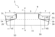
- FIG. 2 is a plan view of the cutting insert shown in FIG. 1 .
- FIG. 2 is a bottom plan view of the cutting insert shown in FIG. 1 .
- FIG. 3 is a side view of the cutting insert shown in FIG. 2 as viewed from an A1 direction.
- 5 is a cross-sectional view taken along the line VV of the cutting insert shown in FIG. 4.
- 6 is a cross-sectional view of the cutting insert shown in FIG. 4 taken along line VI-VI.
- 7 is a cross-sectional view of the cutting insert shown in FIG. 4 taken along line VII-VII.
- FIG. 6 is an enlarged view of region VIII shown in FIG. 5 .
- FIG. 1 is a perspective view of a non-limiting one-sided cutting tool of the present disclosure.
- FIG. 10 is an enlarged view of a region X shown in FIG. 9 .
- FIG. 2 is a schematic diagram showing a step in a non-limiting method of manufacturing a one-sided machined product according to the present disclosure.
- FIG. 2 is a schematic diagram showing a step in a non-limiting method of manufacturing a one-sided machined product according to the present disclosure.
- FIG. 2 is a schematic diagram showing a step in a non-limiting method of manufacturing a one-sided machined product according to the present disclosure.
- the non-limiting one-sided cutting insert 1 (hereinafter, simply referred to as the insert 1) of the present disclosure will be described in detail with reference to the drawings.
- the insert 1 may include any component member not shown in each of the drawings referred to.
- the dimensions of the components in each drawing do not faithfully represent the dimensions of the actual components and the dimensional ratios of each component.
- the insert 1 may be rod-shaped extending from a first end 1a to a second end 1b along a central axis O1, as shown in a non-limiting example in FIG. 1.
- the insert 1 may be prism-shaped extending from a first end 1a to a second end 1b along a central axis O1.
- the insert 1 may have a body portion 3, a first cutting portion 5, and a second cutting portion 7.
- the first cutting portion 5 may be located closer to the first end 1a than the body portion 3.
- the second cutting portion 7 may be located closer to the second end 1b than the body portion 3.
- the first cutting portion 5 includes the first end 1a
- the second cutting portion 7 includes the second end 1b.
- the first cutting portion 5 and the second cutting portion 7 may be portions that come into contact with the workpiece when the workpiece is cut using the insert 1, and play a primary role in the cutting process. However, it is not necessary for the first cutting portion 5 and the second cutting portion 7 to come into contact with the workpiece at the same time, and it is sufficient for only one of the first cutting portion 5 or the second cutting portion 7 to play a primary role in the cutting process.
- An insert 1 in which cutting portions are located at both ends in the direction along the central axis O1 in this manner is generally referred to as a two-cornered dogbone type.
- the main body portion 3 may be a portion located at the center of the insert 1 in the direction along the central axis O1, and may be a portion that is restrained by the holder when the insert 1 is attached to the holder described below.
- the main body portion 3 may have a first upper surface 9 and a first lower surface 11.
- the first upper surface 9 may have an upper groove 13 extending along the central axis O1.
- the first lower surface 11 may be a portion located on the opposite side of the first upper surface 9, and may have a first lower groove 15 extending along the central axis O1.
- first upper surface 9 and the first lower surface 11 are expressions for convenience and do not indicate an upward and downward direction.
- first upper surface 9 does not need to face upward when the insert 1 is in use.
- positional relationship in the upward and downward direction may be specified by taking the direction perpendicular to the central axis O1 from the central axis O1 toward the first upper surface 9 as "upward” and the direction from the central axis O1 toward the first lower surface 11 as “downward.” These points are the same for other parts that include the expressions "upward” and "downward.”
- the upper groove 13 may be V-shaped opening upward, and the first lower groove 15 may be V-shaped opening downward.
- the upper groove 13 has an upper bottom surface 17 having a concave curved shape and a pair of upper restraining surfaces 19 extending upward from the upper bottom surface 17.
- the upper bottom surface 17 may be the portion of the upper groove 13 closest to the central axis O1.
- the pair of upper restraining surfaces 19 may have a pair of upper straight line portions 19a each extending from the upper base surface 17 shown in a concave curved shape.
- the angle formed by the pair of upper straight line portions 19a in this cross section may be the upper opening angle ⁇ 0. Note that, if the upper base surface 17 is located between the pair of upper restraining surfaces 19, the upper opening angle ⁇ 0 may be evaluated by virtually extending and intersecting the upper straight line portions 19a.
- the opening angle is also called the wedge angle.
- the first lower groove 15 has a first lower bottom surface 21 having a concave curved shape, and a pair of first lower restraint surfaces 23 extending downward from the first lower bottom surface 21.
- the pair of upper restraint surfaces 19 and the pair of first lower restraint surfaces 23 abut against the holder, thereby allowing the insert 1 to be stably restrained to the holder.
- the opening angle of the first lower groove 15 in a cross section perpendicular to the central axis O1 may be the first opening angle ⁇ 1 (see FIG. 5).
- the first opening angle ⁇ 1 may be referred to as the first lower opening angle ⁇ 1.
- the pair of first lower restraining surfaces 23 may have a pair of first lower straight line portions 23a each extending from the first lower bottom surface 21 shown in a concave curved shape.
- the opening angle of the pair of first lower straight line portions 23a in this cross section may be the first lower opening angle ⁇ 1.
- the angle formed by the pair of first lower straight line portions 23a in this cross section may be the first lower opening angle ⁇ 1.
- the first lower opening angle ⁇ 1 may be evaluated by virtually extending and intersecting the first lower straight line portion 23a.
- the first lower bottom surface 21 may be the portion of the first lower groove 15 closest to the central axis O1.
- the first cutting portion 5 may have a first end surface 25, a second upper surface 27, a second lower surface 29, and a first cutting edge 31.
- the first end surface 25 may be a surface located at the first end 1a of the first cutting portion 5. Since the first cutting portion 5 is located on the side of the first end 1a of the insert 1, it can be said that the first end surface 25 is located at the first end 1a of the insert 1.
- the second upper surface 27 may be a surface located above the first cutting portion 5, and may extend from the first end surface 25 to the first upper surface 9. As shown in a non-limiting example in FIG. 2, the second upper surface 27 may not have an upper groove 13 formed thereon for restraining it to the holder.
- the second lower surface 29 may be a surface located below the first cutting portion 5, and may extend from the first end face 25 to the first lower surface 11.
- the second lower surface 29 may also have a second lower groove 33 extending along the central axis O1. In a cross section perpendicular to the central axis O1, the second lower groove 33 may be V-shaped and open downward, similar to the first lower groove 15.
- the second lower groove 33 has a second lower bottom surface 35 having a concave curved shape and a pair of second lower restraining surfaces 37 extending downward from the second lower bottom surface 35.
- the second lower groove 33 may be used to restrain the insert 1 to the holder.
- the opening angle of the second lower groove 33 in a cross section perpendicular to the central axis O1 may be the second opening angle ⁇ 2 (see FIG. 6).
- the second opening angle ⁇ 2 may be referred to as the second lower opening angle ⁇ 2.
- the pair of second lower restraining surfaces 37 may have a pair of second lower straight line portions 37a each extending from the second lower bottom surface 35 shown in a concave curved shape.
- the angle formed by the pair of second lower straight line portions 37a in this cross section may be the second lower opening angle ⁇ 2.
- the second lower opening angle ⁇ 2 may be evaluated by virtually extending and intersecting the second lower straight line portion 37a.
- the second lower bottom surface 35 may be the portion of the second lower groove 33 closest to the central axis O1.
- the first cutting edge 31 may be a portion that plays a main role in cutting the workpiece, and may be located at the intersection of the first end face 25 and the second top face 27.
- the first cutting edge 31 may be located over the entire intersection of the first end face 25 and the second top face 27, or may be located over only a portion of the intersection of the first end face 25 and the second top face 27.
- the second top face 27 may function as a scooping surface, and the first end face 25 may function as a clearance surface.
- the first cutting edge 31 is generally called a leading cutting edge or a main cutting edge.
- the second cutting portion 7 may have a second end surface 39, a third upper surface 41, a third lower surface 43, and a second cutting edge 45.
- the second end surface 39 may be a surface located at the second end 1b of the second cutting portion 7. Since the second cutting portion 7 is located on the side of the second end 1b of the insert 1, it can be said that the second end surface 39 is located at the second end 1b of the insert 1.
- the third upper surface 41 may be a surface located above the second cutting portion 7, and may extend from the second end surface 39 to the first upper surface 9. As shown in a non-limiting example in FIG. 2, the third upper surface 41 does not need to have an upper groove 13 formed thereon for restraining it to the holder.
- the third lower surface 43 may be a surface located below the second cutting portion 7, and may extend from the second end surface 39 to the first lower surface 11.
- the third lower surface 43 may also have a third lower groove 47 extending along the central axis O1. In a cross section perpendicular to the central axis O1, the third lower groove 47 may be V-shaped and open downward, similar to the first lower groove 15.
- the third lower groove 47 may have a third lower bottom surface 49 having a concave curved shape and a pair of third lower restraining surfaces 51 extending downward from the third lower bottom surface 49.
- the third lower groove 47 may be used to restrain the insert 1 to the holder.
- the opening angle of the third lower groove 47 in a cross section perpendicular to the central axis O1 may be the third opening angle ⁇ 3 (see FIG. 7).
- the third opening angle ⁇ 3 may be referred to as the third lower opening angle ⁇ 3.
- the pair of third lower restraining surfaces 51 may have a pair of third lower straight portions 51a each extending from the third lower bottom surface 49 shown in a concave curved shape.
- the angle formed by the pair of third lower straight portions 51a in this cross section may be the third lower opening angle ⁇ 3.
- the third lower opening angle ⁇ 3 may be evaluated by virtually extending and intersecting the third lower straight portion 51a.
- the third lower bottom surface 49 may be the portion of the third lower groove 47 closest to the central axis O1.
- the second cutting edge 45 may be a portion that plays a major role in cutting the workpiece, and may be located at the intersection of the second end face 39 and the third top face 41.
- the second cutting edge 45 may be located over the entire intersection of the second end face 39 and the third top face 41, or may be located over only a portion of the intersection of the second end face 39 and the third top face 41.
- the third top face 41 may function as a scooping surface
- the second end face 39 may function as a clearance surface.
- the second cutting edge 45 like the first cutting edge 31, is generally called a leading cutting edge or a main cutting edge.
- the first downward opening angle ⁇ 1 may be greater than the second downward opening angle ⁇ 2 and the third downward opening angle ⁇ 3. In this case, it is possible to ensure a high level of both durability against the load applied to the insert 1 when it is held in the holder and stability of holding by the holder. This is for the following reasons.
- the cutting insert 1 is highly durable against the load applied when held in the holder.
- the second downward opening angle ⁇ 2 in the first cutting portion 5 and the third downward opening angle ⁇ 3 in the second cutting portion 7 are relatively small, whether the first cutting edge 31 or the second cutting edge 45 is used, lateral slippage is unlikely to occur directly below the cutting edge during cutting, and the cutting insert 1 is likely to be held stably by the holder.
- the first downward opening angle ⁇ 1, the second downward opening angle ⁇ 2, and the third downward opening angle ⁇ 3 do not need to be limited to a specific value as long as they satisfy the above relationship.
- the first downward opening angle ⁇ 1 in the main body 3 may be set to 120° to 160°
- the second downward opening angle ⁇ 2 in the first cutting section 5 may be set to 100° to 140°
- the third downward opening angle ⁇ 3 in the second cutting section 7 may be set to 100° to 140°.
- the upward opening angle ⁇ 0 in the main body 3 may be set to 120° to 160°.
- the insert 1 is not limited to a specific size.
- the length of the insert 1 in the direction along the central axis O1 may be set to approximately 18 to 22 mm.
- the width of the insert 1 in the direction perpendicular to the central axis O1 when the first upper surface 9 of the main body 3 is viewed from the front may be set to approximately 2 to 6 mm.
- the height of the insert 1 in the direction perpendicular to the first upper surface 9 may be set to approximately 2 to 6 mm.
- the first downward opening angle ⁇ 1, the second downward opening angle ⁇ 2, and the third downward opening angle ⁇ 3 may each be constant or may vary.
- the first downward opening angle ⁇ 1, the second downward opening angle ⁇ 2, and the third downward opening angle ⁇ 3 are each constant in the direction along the central axis O1.
- the pair of first lower constraint surfaces 23, the pair of second lower constraint surfaces 37, and the pair of third lower constraint surfaces 51 each have a flat surface shape.
- first lower constraint surfaces 23 are flat, it is easy to suppress variation in durability against the clamping force of the holder. If the pair of second lower constraint surfaces 37 are flat, it is easy to suppress variation in durability against the cutting load applied when cutting is performed using the first cutting blade 31. Also, if the pair of third lower constraint surfaces 51 are flat, it is easy to suppress variation in durability against the cutting load applied when cutting is performed using the second cutting blade 45.
- the pair of first lower restraining surfaces 23 may each have another straight line portion in addition to the first lower straight line portion 23a.
- the first lower groove 15 may further have, in addition to the bottom surface 21 (first lower bottom surface 21) and the pair of first straight line portions 23a (first lower straight line portions 23a), a pair of second straight line portions 23b extending from the pair of first straight line portions 23a and inclined with respect to the pair of first straight line portions 23a.
- the length of the second straight line portion 23b may be shorter than the length of the first straight line portion 23a.
- the opening angle of the pair of second straight line portions 23b may be the fourth opening angle ⁇ 4 (fourth downward opening angle ⁇ 4).
- the angle formed by the pair of second straight line portions 23b in this cross section may be the fourth downward opening angle ⁇ 4.
- the fourth downward opening angle ⁇ 4 may be evaluated by virtually extending and intersecting the second straight line portions 23b.
- the fourth lower opening angle ⁇ 4 may be smaller than the first lower opening angle ⁇ 1.
- the first lower groove 15 has the above configuration, the effect of preventing lateral slippage in the main body portion 3 is enhanced while ensuring the effect of improving durability against the clamping force of the holder in the main body portion 3.
- the fourth bottom opening angle ⁇ 4 may be smaller than the second bottom opening angle ⁇ 2 and the third bottom opening angle ⁇ 3. In this case, the effect of preventing lateral slippage of the insert 1 as a whole is improved without making the second bottom opening angle ⁇ 2 in the first cutting portion 5 and the third bottom opening angle ⁇ 3 in the second cutting portion 7 extremely small.
- the fourth bottom opening angle ⁇ 4 is not limited to a specific value and may be set, for example, between 90° and 150°.
- the second lower surface 29 of the first cutting portion 5 may further have a slit 53 (first slit 53) located on the side of the second end 1b in addition to the second lower groove 33.
- the second lower groove 33 may be separated from the first lower groove 15 via the first slit 53.
- the second lower surface 29 has the above-mentioned first slit 53, it is easy to stably attach the insert 1 to the holder. This is because the first lower groove 15 and the second lower groove 33 can be easily and stably brought into contact with the holder even if the insert 1 is slightly misaligned with respect to the holder when attaching the insert 1 to the holder.
- the first slit 53 may extend in a direction perpendicular to the central axis O1. More specifically, when the second lower surface 29 is viewed from the front, the first slit 53 may extend in a direction perpendicular to the central axis O1. In this case, even if the insert 1 is slightly misaligned with respect to the holder, the first lower groove 15 and the second lower groove 33 can be more stably brought into contact with the holder.
- the third lower surface 43 of the second cutting portion 7 may further have a second slit 55 located on the side of the first end 1a in addition to the third lower groove 47.
- the third lower groove 47 may be separated from the first lower groove 15 via the second slit 55.
- the third lower surface 43 has the above-mentioned second slit 55, it is easy to stably attach the insert 1 to the holder. This is because the first lower groove 15 and the third lower groove 47 can be easily and stably brought into contact with the holder even if the insert 1 is slightly misaligned with respect to the holder when attaching the insert 1 to the holder.
- the second slit 55 may extend in a direction perpendicular to the central axis O1. In this case, even if the insert 1 is slightly misaligned with respect to the holder, the first lower groove 15 and the third lower groove 47 can be more stably brought into contact with the holder.
- the material of the insert 1 may be, for example, an inorganic material such as cemented carbide, cermet, or ceramics.
- the composition of the cemented carbide may be, for example, WC (tungsten carbide)-Co, WC-TiC (titanium carbide)-Co, or WC-TiC-TaC (tantalum carbide)-Co.
- WC, TiC, and TaC may be hard particles
- Co may be a binder phase.
- the cermet may also be a sintered composite material in which a ceramic component is combined with a metal.
- the cermet may be a compound whose main component is TiC or TiN (titanium nitride). It goes without saying that the material of the insert 1 is not limited to these.
- the insert 1 may have a main body (base) containing the above-mentioned material and a coating layer that covers the main body.
- materials for the coating layer include titanium carbides, nitrides, oxides, carbonates, oxynitrides, carbonitrides, and oxycarbonitrides.
- the coating layer may contain only one of the above materials, or may contain more than one.
- the coating layer may also be composed of only one layer, or may be composed of multiple layers stacked together.
- the materials of the coating layer are not limited to these.
- the coating layer may be disposed on the substrate by using chemical vapor deposition (CVD) or physical vapor deposition (PVD) techniques.
- CVD chemical vapor deposition
- PVD physical vapor deposition
- the cutting tool 101 may have a holder 103 and an insert 1.
- the cutting tool 101 has the insert 1, it is possible to ensure a high level of both durability against the load applied to the insert 1 when it is held in the holder 103 and stability of holding by the holder 103, and therefore excellent cutting performance can be exhibited.
- the holder 103 may be rod-shaped. Also, as shown in a non-limiting example in FIG. 9, the holder 103 may be rod-shaped extending from the tip 103a (lower left end in FIG. 9) to the rear end 103b (upper right end in FIG. 9). The holder 103 may be rod-shaped extending from the tip 103a to the rear end 103b.
- the holder 103 may also have a pocket 105 located at the tip 103a.
- the holder 103 may have an upper jaw 107 and a lower jaw 109 located on the side of the tip 103a and spaced apart from each other.
- the upper jaw 107 and the lower jaw 109 may form the pocket 105.
- the insert 1 may be located within the pocket 105. In other words, the insert 1 may be sandwiched between the upper jaw 107 and the lower jaw 109. The insert 1 may be attached such that at least a portion of the portion used as the cutting edge protrudes outward from the holder 103.
- the material of the holder 103 may be, for example, steel or cast iron. If the material of the holder 103 is steel, the holder 103 has high toughness.
- a cutting tool 101 used for so-called turning is shown.
- the cutting tool 101 can be used for groove cutting, but is not limited to such cutting.
- there is no problem with the cutting tool 101 being used for internal diameter cutting, external diameter cutting, and traverse feed cutting.
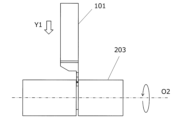
- the machined product 201 may be produced by cutting a workpiece 203.
- a manufacturing method of the machined product 201 may include the following steps. That is, (1) rotating the workpiece 203; (2) contacting a rotating workpiece 203 with a cutting tool 101, such as that typified by the above-described embodiments; (3) removing the cutting tool 101 from the workpiece 203;
- the device may include:
- the cutting tool 101 is moved in each process to bring the cutting tool 101 into contact with the workpiece 203 or to move the cutting tool 101 away from the workpiece 203, but of course the present invention is not limited to this form.
- step (1) the workpiece 203 may be brought closer to the cutting tool 101.
- step (3) the workpiece 203 may be moved away from the cutting tool 101. If cutting is to be continued, the workpiece 203 may be kept rotating and the step of bringing the cutting edge of the insert 1 into contact with different locations on the workpiece 203 may be repeated.
- examples of the material of the workpiece 203 include carbon steel, alloy steel, stainless steel, cast iron, and non-ferrous metals.
- a cutting insert has a rod shape extending from a first end to a second end along a central axis, and has a main body, a first cutting portion located closer to the first end than the main body, and a second cutting portion located closer to the second end than the main body, the main body having a first upper surface having an upper groove extending along the central axis, and a first lower surface located opposite the first upper surface and having a first lower groove extending along the central axis, the first cutting portion having a first end surface located at the first end, a second upper surface extending from the first end surface to the first upper surface, a second lower surface extending from the first end surface to the first lower surface and having a second lower groove extending along the central axis, and a first cutting portion having a first end surface located at the first end, a second upper surface extending from the first end surface to the first lower surface and having a second lower groove extending along the central axis, and a first cutting portion having a first end surface located at the first end,
- the first opening angle, the second opening angle, and the third opening angle may each be constant in a direction along the central axis.
- the first lower groove in a cross section perpendicular to the central axis, has a bottom surface having a concave curved shape, a pair of first straight portions each extending from the bottom surface, and a pair of second straight portions extending from the pair of first straight portions and inclined relative to the pair of first straight portions, wherein an opening angle at the pair of first straight portions is the first opening angle, an opening angle at the pair of second straight portions is a fourth opening angle, and the fourth opening angle may be smaller than the first opening angle.
- the fourth opening angle may be smaller than the second opening angle and the third opening angle.
- the second lower surface may further have a slit located on the side of the second end, and the second lower groove may be separated from the first lower groove via the slit.
- the slit may extend in a direction perpendicular to the central axis.
- the cutting tool may have a rod shape extending from a tip to a rear end, a holder having a pocket located at the tip, and a cutting insert according to any one of (1) to (6) above located in the pocket.
- a method for manufacturing a machined product can include the steps of rotating a workpiece, contacting the rotating workpiece with the cutting tool described above in (7), and removing the cutting tool from the workpiece.
Landscapes
- Engineering & Computer Science (AREA)
- Mechanical Engineering (AREA)
- Cutting Tools, Boring Holders, And Turrets (AREA)
Priority Applications (1)
| Application Number | Priority Date | Filing Date | Title |
|---|---|---|---|
| JP2025512421A JPWO2024209781A1 (https=) | 2023-04-04 | 2024-02-07 |
Applications Claiming Priority (2)
| Application Number | Priority Date | Filing Date | Title |
|---|---|---|---|
| JP2023-060565 | 2023-04-04 | ||
| JP2023060565 | 2023-04-04 |
Publications (1)
| Publication Number | Publication Date |
|---|---|
| WO2024209781A1 true WO2024209781A1 (ja) | 2024-10-10 |
Family
ID=92971958
Family Applications (1)
| Application Number | Title | Priority Date | Filing Date |
|---|---|---|---|
| PCT/JP2024/004024 Ceased WO2024209781A1 (ja) | 2023-04-04 | 2024-02-07 | 切削インサート、切削工具及び切削加工物の製造方法 |
Country Status (2)
| Country | Link |
|---|---|
| JP (1) | JPWO2024209781A1 (https=) |
| WO (1) | WO2024209781A1 (https=) |
Citations (4)
| Publication number | Priority date | Publication date | Assignee | Title |
|---|---|---|---|---|
| JP2007210051A (ja) * | 2006-02-08 | 2007-08-23 | Mitsubishi Materials Corp | 切削インサート及びインサート着脱式切削工具 |
| JP2007253299A (ja) * | 2006-03-24 | 2007-10-04 | Mitsubishi Materials Corp | 切削インサートのクランプ機構、切削インサート及びインサート着脱式切削工具 |
| US20110255926A1 (en) * | 2010-04-14 | 2011-10-20 | Iscar, Ltd. | Cutting Tool and Cutting Insert Therefor |
| WO2023277182A1 (ja) * | 2021-07-01 | 2023-01-05 | 京セラ株式会社 | 切削インサート、切削工具及び切削加工物の製造方法 |
-
2024
- 2024-02-07 WO PCT/JP2024/004024 patent/WO2024209781A1/ja not_active Ceased
- 2024-02-07 JP JP2025512421A patent/JPWO2024209781A1/ja active Pending
Patent Citations (4)
| Publication number | Priority date | Publication date | Assignee | Title |
|---|---|---|---|---|
| JP2007210051A (ja) * | 2006-02-08 | 2007-08-23 | Mitsubishi Materials Corp | 切削インサート及びインサート着脱式切削工具 |
| JP2007253299A (ja) * | 2006-03-24 | 2007-10-04 | Mitsubishi Materials Corp | 切削インサートのクランプ機構、切削インサート及びインサート着脱式切削工具 |
| US20110255926A1 (en) * | 2010-04-14 | 2011-10-20 | Iscar, Ltd. | Cutting Tool and Cutting Insert Therefor |
| WO2023277182A1 (ja) * | 2021-07-01 | 2023-01-05 | 京セラ株式会社 | 切削インサート、切削工具及び切削加工物の製造方法 |
Also Published As
| Publication number | Publication date |
|---|---|
| JPWO2024209781A1 (https=) | 2024-10-10 |
Similar Documents
| Publication | Publication Date | Title |
|---|---|---|
| JP5639656B2 (ja) | 切削インサートおよび切削工具、並びにそれらを用いた切削加工物の製造方法 | |
| JP7480291B2 (ja) | 切削インサート、切削工具及び切削加工物の製造方法 | |
| US20210260669A1 (en) | Cutting insert, cutting tool, and method for manufacturing machined product | |
| JP6272457B2 (ja) | 切削インサート、切削工具及び切削加工物の製造方法 | |
| JPWO2019065525A1 (ja) | 切削インサート、切削工具及び切削加工物の製造方法 | |
| WO2021235261A1 (ja) | 切削インサート、切削工具、および切削加工物の製造方法 | |
| CN110944777B (zh) | 切削刀片、切削工具以及切削加工物的制造方法 | |
| WO2020203414A1 (ja) | 切削インサート、旋削工具及び切削加工物の製造方法 | |
| JP7594672B2 (ja) | 切削インサート、切削工具及び切削加工物の製造方法 | |
| JP7592867B2 (ja) | 切削インサート、切削工具及び切削加工物の製造方法 | |
| WO2024209781A1 (ja) | 切削インサート、切削工具及び切削加工物の製造方法 | |
| JP7155397B2 (ja) | 切削インサート、切削工具及び切削加工物の製造方法 | |
| KR102540681B1 (ko) | 절삭 인서트, 절삭 공구 및 절삭 가공물의 제조 방법 | |
| WO2023176441A1 (ja) | 切削工具及び切削加工物の製造方法 | |
| JP7527489B2 (ja) | ホルダ、切削工具及び切削加工物の製造方法 | |
| US12115587B2 (en) | Cutting insert, cutting tool, and method for manufacturing machined product | |
| JP7204882B2 (ja) | 切削インサート、切削工具及び切削加工物の製造方法 | |
| JP7455964B2 (ja) | 切削インサート、切削工具および切削加工物の製造方法 | |
| WO2025063046A1 (ja) | 切削インサート、切削工具、及び切削加工物の製造方法 | |
| JP7239480B2 (ja) | 切削インサート、切削工具及び切削加工物の製造方法 | |
| WO2025216120A1 (ja) | 切削インサート、切削工具及び切削加工物の製造方法 | |
| WO2024202230A1 (ja) | 切削インサート、切削工具及び切削加工物の製造方法 | |
| JPWO2019146645A1 (ja) | 切削インサート、切削工具及び切削加工物の製造方法 |
Legal Events
| Date | Code | Title | Description |
|---|---|---|---|
| 121 | Ep: the epo has been informed by wipo that ep was designated in this application |
Ref document number: 24784584 Country of ref document: EP Kind code of ref document: A1 |
|
| ENP | Entry into the national phase |
Ref document number: 2025512421 Country of ref document: JP Kind code of ref document: A |
|
| WWE | Wipo information: entry into national phase |
Ref document number: 2025512421 Country of ref document: JP |
|
| NENP | Non-entry into the national phase |
Ref country code: DE |
|
| 122 | Ep: pct application non-entry in european phase |
Ref document number: 24784584 Country of ref document: EP Kind code of ref document: A1 |