WO2024204683A1 - 粘着シート及び剥離方法 - Google Patents
粘着シート及び剥離方法 Download PDFInfo
- Publication number
- WO2024204683A1 WO2024204683A1 PCT/JP2024/012979 JP2024012979W WO2024204683A1 WO 2024204683 A1 WO2024204683 A1 WO 2024204683A1 JP 2024012979 W JP2024012979 W JP 2024012979W WO 2024204683 A1 WO2024204683 A1 WO 2024204683A1
- Authority
- WO
- WIPO (PCT)
- Prior art keywords
- adhesive sheet
- adhesive layer
- resin
- less
- adhesive
- Prior art date
- Legal status (The legal status is an assumption and is not a legal conclusion. Google has not performed a legal analysis and makes no representation as to the accuracy of the status listed.)
- Ceased
Links
Images






Classifications
-
- C—CHEMISTRY; METALLURGY
- C09—DYES; PAINTS; POLISHES; NATURAL RESINS; ADHESIVES; COMPOSITIONS NOT OTHERWISE PROVIDED FOR; APPLICATIONS OF MATERIALS NOT OTHERWISE PROVIDED FOR
- C09J—ADHESIVES; NON-MECHANICAL ASPECTS OF ADHESIVE PROCESSES IN GENERAL; ADHESIVE PROCESSES NOT PROVIDED FOR ELSEWHERE; USE OF MATERIALS AS ADHESIVES
- C09J201/00—Adhesives based on unspecified macromolecular compounds
-
- C—CHEMISTRY; METALLURGY
- C09—DYES; PAINTS; POLISHES; NATURAL RESINS; ADHESIVES; COMPOSITIONS NOT OTHERWISE PROVIDED FOR; APPLICATIONS OF MATERIALS NOT OTHERWISE PROVIDED FOR
- C09J—ADHESIVES; NON-MECHANICAL ASPECTS OF ADHESIVE PROCESSES IN GENERAL; ADHESIVE PROCESSES NOT PROVIDED FOR ELSEWHERE; USE OF MATERIALS AS ADHESIVES
- C09J7/00—Adhesives in the form of films or foils
- C09J7/30—Adhesives in the form of films or foils characterised by the adhesive composition
- C09J7/38—Pressure-sensitive adhesives [PSA]
-
- C—CHEMISTRY; METALLURGY
- C09—DYES; PAINTS; POLISHES; NATURAL RESINS; ADHESIVES; COMPOSITIONS NOT OTHERWISE PROVIDED FOR; APPLICATIONS OF MATERIALS NOT OTHERWISE PROVIDED FOR
- C09J—ADHESIVES; NON-MECHANICAL ASPECTS OF ADHESIVE PROCESSES IN GENERAL; ADHESIVE PROCESSES NOT PROVIDED FOR ELSEWHERE; USE OF MATERIALS AS ADHESIVES
- C09J2301/00—Additional features of adhesives in the form of films or foils
- C09J2301/20—Additional features of adhesives in the form of films or foils characterized by the structural features of the adhesive itself
-
- C—CHEMISTRY; METALLURGY
- C09—DYES; PAINTS; POLISHES; NATURAL RESINS; ADHESIVES; COMPOSITIONS NOT OTHERWISE PROVIDED FOR; APPLICATIONS OF MATERIALS NOT OTHERWISE PROVIDED FOR
- C09J—ADHESIVES; NON-MECHANICAL ASPECTS OF ADHESIVE PROCESSES IN GENERAL; ADHESIVE PROCESSES NOT PROVIDED FOR ELSEWHERE; USE OF MATERIALS AS ADHESIVES
- C09J2301/00—Additional features of adhesives in the form of films or foils
- C09J2301/30—Additional features of adhesives in the form of films or foils characterized by the chemical, physicochemical or physical properties of the adhesive or the carrier
- C09J2301/308—Additional features of adhesives in the form of films or foils characterized by the chemical, physicochemical or physical properties of the adhesive or the carrier the adhesive tape or sheet losing adhesive strength when being stretched, e.g. stretch adhesive
Definitions
- the present invention relates to an adhesive sheet and a peeling method.
- Adhesive sheets that temporarily hold an object are known. Such adhesive sheets can be used to transfer an object to a desired location.
- Adhesive sheets come in a variety of shapes depending on their application.
- Patent Document 1 discloses a technology that allows a functional adhesive sheet to be firmly attached to an adherend while also allowing the adhesive sheet to be temporarily attached.
- Adhesive sheets that temporarily hold objects are required to have a certain degree of retention of the object, as well as to be able to easily remove the object.
- the objective of the present invention is to provide an adhesive sheet that has a certain degree of retention of an object while having a structure that allows the object to be peeled off.
- the inventors discovered that the above-mentioned problems could be solved by providing the surface of the adhesive layer with irregularities having protrusions of different heights, which allows the adhesive sheet to retain a certain degree of adhesion to an object while making it easier to remove the object. After further research, the inventors have completed the present invention.
- An adhesive sheet having an adhesive layer for holding an object,
- the adhesive layer has an uneven surface, a base portion including a portion from a concave portion where the thickness of the adhesive layer is smallest to a surface opposite to the surface having the concaves and convexes in a thickness direction of the adhesive layer; a first portion provided on the base portion to have a first height; a second portion provided on the base portion so as to have a second height different from the first height;
- An adhesive sheet comprising: [2] The pressure-sensitive adhesive sheet according to [1], wherein the difference between the first height and the second height is 1 ⁇ m or more and 40 ⁇ m or less.
- the first portion is a first convex portion provided on the base portion, The pressure-sensitive adhesive sheet according to [1] or [2], wherein the second portion is a second convex portion provided on the base portion and different from the first convex portion.
- the first height is greater than the second height, The pressure-sensitive adhesive sheet according to any one of [1] to [3], wherein the number of the first convex portions is smaller than the number of the second convex portions.
- the first height is greater than the second height, The pressure-sensitive adhesive sheet according to any one of [1] to [4], wherein an area occupied by the first convex portions in the pressure-sensitive adhesive layer is smaller than an area occupied by the second convex portions.
- a method for peeling an object from an adhesive sheet comprising: an expansion step of expanding, in a planar direction, the adhesive sheet according to any one of [1] to [9], which holds an object on an adhesive layer; and a peeling step of peeling the object from the adhesive layer of the adhesive sheet expanded in the planar direction.
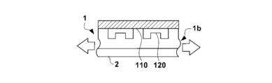
- FIG. 2 is a cross-sectional view of a pressure-sensitive adhesive sheet according to an embodiment.
- 1A to 1C are diagrams showing a method for holding and peeling an object using an adhesive sheet.
- 1A to 1C are diagrams showing a method for holding and peeling an object using an adhesive sheet.
- 1A to 1C are diagrams showing a method for holding and peeling an object using an adhesive sheet.
- 1A to 1C are diagrams showing a method for holding and peeling an object using an adhesive sheet.
- FIG. 4 is a cross-sectional view showing an example of projections and recesses on a pressure-sensitive adhesive sheet.
- FIG. 3 is a cross-sectional view showing an example of projections and recesses on a pressure-sensitive adhesive sheet.
- FIG. 2 is a plan view of a pressure-sensitive adhesive sheet according to an embodiment.
- FIG. 4 is a plan view showing an example of projections and recesses on an adhesive sheet.
- FIG. 4 is a plan view showing an example of projections and recesses on an adhesive sheet.
- FIG. 4 is a plan view showing an example of projections and recesses on an adhesive sheet.
- the mass average molecular weight (Mw) and the number average molecular weight (Mn) are values calculated in terms of standard polystyrene measured by size exclusion chromatography, specifically, values measured based on JIS K7252-1: 2016.
- (meth)acrylic acid is a term that refers to both "acrylic acid” and “methacrylic acid”, and the same applies to other similar terms.
- a description that is preferably 1 or more, more preferably 2 or more, even more preferably 3 or more, and preferably 9 or less, more preferably 8 or less, even more preferably 7 or less clearly means that the numerical range may be any of 1 or more and 9 or less, 1 or more and 8 or less, 1 or more and 7 or less, 2 or more and 9 or less, 2 or more and 8 or less, 2 or more and 7 or less, 3 or more and 9 or less, 3 or more and 8 or less, and 3 or more and 7 or less.
- An adhesive sheet according to one embodiment of the present invention includes an adhesive layer 1 for holding an object.
- the adhesive sheet may include an adhesive layer 1 and a substrate 2 supporting the adhesive layer 1.
- Fig. 1 is a schematic diagram of an adhesive sheet according to one embodiment.
- the adhesive layer 1 may be provided on a substrate 2.
- a substrate 2 For example, as shown in FIG. 1, an adhesive sheet including an adhesive layer 1 and a substrate 2 can be used. However, it is not essential that the adhesive sheet has a substrate 2.
- the adhesive sheet may be composed of only the adhesive layer 1. In this case, an adhesive layer 1 having high support can be used.
- the substrate 2 functions as a support for the adhesive layer 1.
- the substrate 2 is located on the surface F1 opposite to the surface of the adhesive layer 1 having the irregularities 1a.
- the type of substrate 2 is not particularly limited, and may be a hard substrate or a flexible substrate. From the viewpoints of improving cushioning when holding the object 4, facilitating attachment to the object 4, improving peelability, facilitating lamination, or enabling formation into a roll form, it is preferable that the substrate 2 is a flexible substrate.
- a resin film can be used as the substrate 2.
- the resin film is a film that uses a resin-based material as the main material, and may be made of a resin material or may contain additives in addition to the resin material.
- the resin film may be transparent to laser light.
- resin films include polyolefin films such as polyethylene films, such as low-density polyethylene films, linear low-density polyethylene films, and high-density polyethylene films, polypropylene films, polybutene films, polybutadiene films, polymethylpentene films, ethylene-norbornene copolymer films, and norbornene resin films; ethylene copolymer films, such as ethylene-vinyl acetate copolymer films, ethylene-(meth)acrylic acid copolymer films, and ethylene-(meth)acrylic acid ester copolymer films; polyvinyl chloride films, such as polyvinyl chloride films and vinyl chloride copolymer films; polyester films, such as polyethylene terephthalate films and polybutylene terephthalate films; polyurethane films; polyimide films; polystyrene films; polycarbonate films; and fluororesin films.
- polyethylene films such as low-density polyethylene films, linear
- films containing a mixture of two or more types of materials, crosslinked films in which the resins forming these films are crosslinked, and modified films such as ionomer films may be used.
- the substrate 2 may be a laminate film in which two or more types of resin films are laminated.
- the resin film be a single-layer film selected from the group consisting of polyethylene films, polyester films, and polypropylene films, or a laminate film in which two or more types of films selected from this group are laminated.
- the thickness of the substrate 2 is not particularly limited, but from the viewpoint of achieving both supportability and roll winding properties, it is preferably in the range of 10 ⁇ m to 500 ⁇ m, more preferably 25 ⁇ m to 200 ⁇ m, and even more preferably 40 ⁇ m to 90 ⁇ m.
- the adhesive sheet is expanded when peeling it off from the object 4.
- the tensile modulus of the substrate 2 is preferably 50 MPa or more, more preferably 80 MPa or more, even more preferably 120 MPa or more, and is preferably 2500 MPa or less, more preferably 1000 MPa or less, even more preferably 200 MPa or less.
- the tensile modulus refers to a value measured by the method described in the examples.
- the breaking elongation of the substrate 2 is preferably 105% or more, more preferably 110% or more, and even more preferably 115% or more.
- the breaking elongation is measured in accordance with JIS C2151:2019.
- the substrate 2 is preferably a polyolefin film or a vinyl chloride copolymer film.
- polyolefin films include polyethylene films, polypropylene films, and ethylene copolymers including ethylene-methacrylic acid copolymers.
- vinyl chloride copolymer films include vinyl chloride-vinylidene chloride copolymer films, vinyl chloride-vinyl acetate copolymer films, and vinyl chloride-ethylene copolymer films.
- the adhesive layer 1 is a layer having adhesiveness and may contain a resin. As described later, the adhesive layer 1 has unevenness 1a on its surface.
- the adhesive sheet may have two or more adhesive layers 1.
- the adhesive sheet may have a laminate of one type or two or more types of adhesive layers 1.
- the resin contained in the adhesive layer 1 examples include rubber-based resins such as polyisobutylene-based resins, polybutadiene-based resins, and styrene-butadiene-based resins, acrylic resins, urethane resins, polyester resins, olefin resins, silicone resins, and polyvinyl ether resins.
- the adhesive layer may have heat resistance, and examples of the material of the adhesive layer 1 having such heat resistance include polyimide resins and silicone resins.
- the adhesive layer 1 may contain a copolymer having two or more types of constitutional units. The form of such a copolymer is not particularly limited, and may be any of a block copolymer, a random copolymer, an alternating copolymer, and a graft copolymer.
- the resin contained in the adhesive layer 1 is preferably an adhesive resin having adhesiveness by itself.
- the resin is preferably a polymer having a mass average molecular weight (Mw) of 10,000 or more.
- Mw mass average molecular weight
- the mass average molecular weight (Mw) of the resin is preferably 10,000 or more, more preferably 70,000 or more, and even more preferably 140,000 or more.
- the number average molecular weight (Mn) of the resin is preferably 10,000 or more, more preferably 50,000 or more, and even more preferably 100,000 or more.
- the shear storage modulus is preferably 2 million or less, more preferably 1 million or less, and even more preferably 700,000 or less.
- the mass average molecular weight (Mw) and number average molecular weight (Mn) refer to the mass average molecular weight (Mw) and number average molecular weight (Mn) before the crosslinking reaction due to the application of energy.
- the glass transition temperature (Tg) of the resin is preferably -75°C or higher, more preferably -70°C or higher, and preferably 5°C or lower, more preferably -20°C or lower.
- the amount of resin contained in adhesive layer 1 relative to the total amount of components constituting adhesive layer 1 can be set appropriately depending on the desired retention and shear storage modulus of adhesive layer 1, but is preferably 30% by mass or more, more preferably 40% by mass or more, even more preferably 50% by mass or more, even more preferably 55% by mass or more, even more preferably 60% by mass or more, and is preferably 99.99% by mass or less, more preferably 99.95% by mass or less, even more preferably 99.90% by mass or less, even more preferably 99.80% by mass or less, even more preferably 99.50% by mass or less.
- the shear storage modulus of the adhesive layer 1 is preferably 0.001 MPa or more, more preferably 0.01 MPa or more, even more preferably 0.05 MPa or more, and even more preferably 0.1 MPa or more, from the viewpoint of morphological stability of the uneven shape of the surface of the adhesive layer 1.
- a low shear storage modulus of the adhesive layer 1 is preferable in that it can suppress positional deviation when holding an object.
- the shear storage modulus of the adhesive layer 1 is preferably 100 MPa or less, more preferably 10 MPa or less, even more preferably 5 MPa or less, even more preferably 2 MPa or less, even more preferably 1 MPa or less, and even more preferably 0.5 MPa or less.
- the shear storage modulus means a value measured by the method described in the Examples.
- the resin contained in the adhesive composition forming the adhesive layer 1 may include a thermoplastic resin. That is, the adhesive layer 1 can be formed from a thermoplastic resin. When a thermoplastic resin is used, it becomes easy to form the unevenness 1a in the adhesive layer 1 by heating the resin to soften it, and it becomes easy to maintain the uneven shape formed by cooling the resin.
- thermoplastic resins include rubber-based resins, acrylic-based resins, urethane-based resins, and olefin-based resins.
- Examples include polybutadiene-based thermoplastic elastomers using butadiene as a monomer, styrene-based thermoplastic elastomers using styrene as a monomer, and acrylic-based thermoplastic elastomers using (meth)acrylic acid esters as monomers.
- the resin contained in the adhesive layer 1 is preferably derived from an energy reactive resin.
- An energy reactive resin refers to a resin whose elastic modulus is improved by the application of energy.
- Examples of energy reactive resins include energy ray reactive resins and heat reactive resins.
- An energy ray reactive resin refers to a resin whose elastic modulus is improved by the application of energy rays.
- a heat reactive resin refers to a resin whose elastic modulus is improved by heating.
- the resin contained in the adhesive layer 1 is more preferably derived from a thermoplastic energy reactive resin, and even more preferably derived from a thermoplastic energy ray reactive resin.
- the type of energy ray is not particularly limited, and examples include ultraviolet rays, electron beams, and ionizing radiation.
- the energy ray is preferably ultraviolet rays, that is, the resin is preferably an ultraviolet-reactive resin.
- Thermoplastic energy reactive resin refers to an energy reactive resin that has thermoplastic properties at least before energy is applied.
- a resin derived from an energy reactive resin means that the resin is obtained from an energy reactive resin.
- a resin derived from an energy reactive resin is a crosslinked energy reactive resin.
- a polymerizable functional group is a functional group that is crosslinked by the application of energy (for example, by irradiation with energy rays).
- Examples of such polymerizable functional groups include alkenyl groups such as vinyl groups and allyl groups, (meth)acryloyl groups, oxetanyl groups, and epoxy groups.
- diene rubber composed of a polymer having a polymerizable functional group at the end of the main chain and/or at the side chain can be used as the energy reactive resin.
- Diene rubber refers to a rubbery polymer having a double bond in the polymer main chain.
- Specific examples of diene rubber include polymers using butadiene or isoprene as a monomer (i.e., having butenediyl or pentenediyl groups as structural units).
- Preferred examples of energy reactive resins include polybutadiene resin (PB resin), styrene-butadiene-styrene block copolymer (SBS resin), and styrene-isoprene-styrene block copolymer. These resins can be used as ultraviolet-reactive resins.
- the average number of polymerizable functional groups per molecule in these energy reactive resins is preferably 1.5 or more, more preferably 2 or more, from the viewpoint of making it easier to maintain the uneven shape of the adhesive layer 1.
- this average value is preferably 20 or less, more preferably 15 or less, and even more preferably 10 or less.
- the adhesive layer 1 may contain one type of resin, or may contain two or more types of resin.
- the adhesive layer 1 according to one embodiment contains a resin derived from a liquid resin or an energy-reactive liquid resin, in addition to a resin derived from a thermoplastic resin or a thermoplastic energy-reactive resin.
- the liquid resin refers to a resin that is liquid at room temperature (25°C) before mixing.
- the energy-reactive liquid resin refers to an energy-reactive resin that is liquid at room temperature (25°C) before mixing and before energy is applied.
- the adhesive layer 1 preferably contains a resin derived from an energy-reactive liquid resin, since this makes it easier to maintain the uneven shape of the adhesive layer 1.
- a resin derived from an energy-reactive liquid resin is a diene-based rubber, and a specific example is a polybutadiene-based resin in which butadiene is used as a monomer.
- the adhesive layer 1 contains a combination of a resin derived from a thermoplastic energy reactive resin and a resin derived from an energy reactive liquid resin.
- the adhesive layer 1 contains a combination of a resin derived from an energy ray reactive styrene-based thermoplastic elastomer and a resin derived from a diene rubber, which is an energy ray reactive liquid resin.
- thermoplastic energy beam reactive resin is a resin in which styrene and butadiene are used as monomers, and a particularly preferred example is SBS resin.
- resins in which styrene and butadiene are used as monomers include resins in which only styrene and butadiene are used as monomers, as well as resins in which monomers other than styrene and butadiene are used.
- the mass average molecular weight (Mw) of such a resin is preferably 10,000 or more, more preferably 50,000 or more, even more preferably 100,000 or more, and even more preferably 150,000 or more.
- the mass average molecular weight (Mw) of such a resin is preferably 2 million or less, more preferably 1 million or less, and even more preferably 200,000 or less.
- the number average molecular weight (Mn) of such resins is preferably 10,000 or more, more preferably 30,000 or more, even more preferably 70,000 or more, and even more preferably 130,000 or more, while it is preferably 2 million or less, more preferably 1 million or less, and even more preferably 200,000 or less.
- a preferred example of the energy ray reactive liquid resin is a resin using butadiene as a monomer, and a particularly preferred example is PB resin.
- the resin using butadiene as a monomer includes not only a resin using only butadiene as a monomer, but also a resin using a monomer other than butadiene.
- the mass average molecular weight (Mw) of such a resin is preferably 500 or more, more preferably 1000 or more, even more preferably 2000 or more, and even more preferably 3000 or more, from the viewpoint of increasing the shear storage modulus of the adhesive layer 1.
- the mass average molecular weight (Mw) of such a resin is preferably 500,000 or less, more preferably 100,000 or less, and even more preferably 10,000 or less, from the viewpoint of decreasing the shear storage modulus of the adhesive layer 1.
- the number average molecular weight (Mn) of such resins is preferably 500 or more, more preferably 1000 or more, even more preferably 3000 or more, and even more preferably 120,000 or more, while it is preferably 500,000 or less, more preferably 100,000 or less, and even more preferably 10,000 or less.
- the ratio of the resin derived from the thermoplastic energy reactive resin and the resin derived from the energy reactive liquid resin contained in the adhesive layer 1 can be selected according to the required retention and shear storage modulus of the adhesive layer 1.
- the amount of the resin derived from the energy reactive liquid resin relative to 100 parts by mass of the resin derived from the thermoplastic energy reactive resin may be 10 parts by mass or more, or 30 parts by mass or more, or even 40 parts by mass or more from the viewpoint of increasing retention, while it may be 500 parts by mass or less, or 200 parts by mass or less, or even 150 parts by mass or less from the viewpoint of increasing the shear storage modulus.
- the ratio of the total amount of the resin derived from the thermoplastic energy reactive resin and the resin derived from the energy reactive liquid resin to the total amount of the components constituting the adhesive layer 1 can be selected according to the desired retention and shear storage modulus of the adhesive layer 1.
- this ratio is preferably 30% by mass or more, more preferably 40% by mass or more, even more preferably 50% by mass or more, even more preferably 55% by mass or more, even more preferably 60% by mass or more, and is preferably 99.99% by mass or less, more preferably 99.95% by mass or less, even more preferably 99.90% by mass or less, even more preferably 99.80% by mass or less, even more preferably 99.50% by mass or less.
- the adhesive layer 1 may contain components other than resin.
- the adhesive layer 1 may contain one or more of a tackifier, a polymerization initiator, an ultraviolet absorber, and other additives.
- the polymerization initiator is a component that initiates a crosslinking reaction in response to the application of energy (e.g., irradiation with energy rays).
- energy e.g., irradiation with energy rays.
- the adhesive layer 1 contains an energy reactive resin
- the adhesive layer 1 further contains a polymerization initiator, so that the crosslinking reaction proceeds even when a relatively low amount of energy is applied.
- a photopolymerization initiator for example, a photopolymerization initiator can be used.
- photopolymerization initiators include 1-hydroxycyclohexyl phenyl ketone, benzoin, benzoin methyl ether, benzoin ethyl ether, benzoin propyl ether, benzyl phenyl sulfide, tetramethylthiuram monosulfide, azobisisobutyronitrile, dibenzyl, diacetyl, 8-chloroanthraquinone, and bis(2,4,6-trimethylbenzoyl)phenylphosphine oxide.
- the adhesive layer 1 may contain one type of polymerization initiator, or may contain two or more types of polymerization initiators.
- the content of the polymerization initiator in the adhesive layer 1 is preferably 0.01% by mass or more, more preferably 0.1% by mass or more, and even more preferably 1% by mass or more, from the viewpoint of proceeding with the crosslinking reaction at an appropriate rate, and is preferably 10% by mass or less, more preferably 5% by mass or less, and even more preferably 2% by mass or less.
- ultraviolet absorbers examples include benzotriazole compounds, oxazolic acid amide compounds, and benzophenone compounds.
- additives that may be contained in the adhesive layer 1 include, but are not limited to, hindered amine, benzophenone, or benzotriazole light stabilizers; phenolic antioxidants such as hindered phenol compounds, aromatic amine antioxidants, sulfur antioxidants, or phosphorus antioxidants such as phosphate ester compounds; resin stabilizers such as imidazole resin stabilizers, dithiocarbamate resin stabilizers, phosphorus resin stabilizers, or sulfur ester resin stabilizers; fillers, pigments, extenders, and softeners.
- hindered amine benzophenone, or benzotriazole light stabilizers
- phenolic antioxidants such as hindered phenol compounds, aromatic amine antioxidants, sulfur antioxidants, or phosphorus antioxidants such as phosphate ester compounds
- resin stabilizers such as imidazole resin stabilizers, dithiocarbamate resin stabilizers, phosphorus resin stabilizers, or sulfur ester resin stabilizers
- fillers pigments, extenders, and
- the content of the additives in the adhesive layer 1 is preferably 0.0001% by mass or more, more preferably 0.01% by mass or more, particularly preferably 0.1% by mass or more, even more preferably 1% by mass or more, and is preferably 20% by mass or less, more preferably 10% by mass or less, even more preferably 5% by mass or less.
- the concave portion 10b is located between the convex portions 10a.
- the convex portion 10a includes a first convex portion 110 that is provided on the base portion 1b to have a first height H1, and a second convex portion 120 that is provided on the base portion 1b to have a second height H2 smaller than the first convex portion 110.
- the first height H1 and the second height H2 refer to the height in the vertical direction from the upper surface F2 of the base portion 1b to the top of the protrusion 10a.
- the first height H1 and the second height H2 correspond to the height difference between the tops of the first protrusion 110 and the second protrusion 120 and the surface of the recess 10b in the thickness direction of the adhesive sheet.
- FIG. 2A to 2D show an example of the state when the adhesive sheet of FIG. 1 holds the object 4 and when the object 4 is peeled off from the adhesive sheet.
- FIG. 2A shows an example of the state when the object 4 approaches the adhesive sheet.
- the type of object 4 is not particularly limited.
- the object 4 can be, for example, an element, a wafer, a panel, or a substrate.
- the gas between the adhesive layer 1 and the object 4 is compressed.
- the compressed gas is likely to escape to the outside from between the adhesive layer 1 and the object 4 through the recess 10b. Therefore, by having the surface of the adhesive layer 1 have the unevenness 1a, it becomes easier to prevent the holding position of the object 4 from shifting due to the pressure of the compressed gas.
- FIG. 2B and 2C show an example of the state when the object 4 is held on the adhesive sheet.
- the object 4 first comes into contact with the first convex portion 110.
- the object 4 approaches the second convex portion 120, and as shown in FIG. 2C, the object 4 also comes into contact with the second convex portion 120.
- the object 4 is held by both the first convex portion 110 and the second convex portion 120. In this way, since the object 4 comes into contact with the first convex portion 110 in the initial stage of holding, the repulsive force exerted by the adhesive sheet on the object 4 becomes smaller.
- the adhesive sheet according to one embodiment can suppress the displacement of the holding position of the object 4 while maintaining a certain degree of holding ability of the object 4.
- the second convex portion 120 is separated from the object 4 by expanding the adhesive sheet in the planar direction.
- the object 4 is held by the first convex portion 110 after the adhesive sheet is expanded.
- the contact area between the adhesive sheet and the object 4 can be reduced by the expansion. Therefore, the adhesive sheet is less able to hold the object 4, making it easier to peel off.
- the adhesive layer 1 has an uneven surface 1a, and the protruding portions 10a have parts of different heights, making it easier to peel the object 4 from the adhesive sheet.
- the specific shape of the surface irregularities 1a is not particularly limited.
- the surface irregularities 1a may be an acute-angled shape like a sawtooth wave, a stepped shape like a step wave, a continuous hemispherical shape like a full-wave rectified wave, or a spaced hemispherical shape like a half-wave rectified wave.
- the surface irregularities 1a may also have a shape that is a combination of these.
- FIG. 3A and 3B show cross-sectional views of an adhesive layer 1 according to another embodiment, taken perpendicular to the surface of the adhesive layer 1 and passing through the convex portion 10a'.
- the surface irregularities 1a' may have a curved shape such as a sine wave.
- the surface irregularities 1a' may have an acute shape such as a triangular wave.
- the surface irregularities 1a' have tip portions 110' of the convex portions 10a' that are provided to have a first height H1 on the base portion 1b.
- the irregularities 1a' have inclined portions 120' of the convex portions 10a' that are provided to have a second height H2 on the base portion 1b. Also, in the thickness direction of the adhesive sheet, the first height H1 is greater than the second height H2.
- the adhesive layer 1 shown in Figures 3A and 3B can allow the gas compressed between the object 4 and the object 4 to escape to the outside through the recess 10b' when the object 4 approaches. Therefore, this adhesive sheet can also suppress the displacement of the holding position of the object 4 due to the compressed gas. Also, like the adhesive layer 1 shown in Figures 2A to 2D, when the object 4 approaches, the object 4 first comes into contact with the tip portion 110', and then the inclined portion 120' also comes into contact with the object 4. In this way, the repulsive force that the adhesive sheet exerts on the object 4 is also smaller in this adhesive sheet.
- the adhesive sheet can suppress the displacement of the holding position of the object 4 while maintaining a certain holding ability of the object 4.
- the adhesive layer 1 is expanded in the surface direction.
- the inclined portion 120' can separate from the object 4. Therefore, the contact area between the convex portion 10a' and the object 4 can be reduced, making peeling easier.
- the adhesive layer 1 has an uneven surface 1a', and the protrusions 10' have an inclined portion 120' in addition to the tip portion 110', so that the adhesive sheet has a certain degree of retention of the object 4, while the object 4 can be easily peeled off from the adhesive sheet.
- the difference between the first height H1 and the second height H2 is preferably 0.1 ⁇ m or more, more preferably 0.5 ⁇ m or more, and even more preferably 1 ⁇ m or more, from the viewpoint of improving the releasability of the object 4.
- it is preferably 120 ⁇ m or less, more preferably 80 ⁇ m or less, and even more preferably 40 ⁇ m or less.
- FIG. 4 shows an example of a plan view of an adhesive sheet.
- the adhesive layer 1 has a first convex portion 110 and a second convex portion 120 on its surface, which are separated from each other via a concave portion 10b.
- the first convex portion 110 and the second convex portion 120 may be separated by a concave portion 10b that is continuous throughout the entire adhesive layer 1.
- gas between the adhesive sheet and the object 4 can easily escape to the outside when holding an object.
- gas can easily enter between the adhesive layer 1 and the object 4 through the concave portion 10b during peeling, making it easier to peel the adhesive sheet from the object 4.
- the concave portions 10b located around each of the first convex portion 110 and the second convex portion 120 may continue to the end of the adhesive layer 1. In this way, by providing the concave portion 10b that is continuous to the end of the adhesive layer 1, gas can more easily enter between the object 4 and the adhesive layer 1. Furthermore, these configurations allow the gas compressed between the object 4 and the adhesive layer 1 to efficiently escape to the outside, preventing the object from shifting out of position.
- FIG. 4 shows an example in which the first convex portion 110 and the second convex portion 120 are the same size and arranged alternately, but this is not limited to the above.
- the first convex portion 110 and the second convex portion 120 may be formed to have different sizes.
- the arrangement method may also be adjusted as appropriate.
- the size means the area in which the first convex portion 110 and the second convex portion 120 protrude in a plan view of the adhesive layer 1.
- FIG. 5A to FIG. 5D are diagrams showing an example of a plan view of the adhesive layer.
- the size of the first convex portion 110 may be smaller than the second size.
- the area of the first convex portion 120 per unit area of the adhesive sheet may be adjusted to be smaller than the area of the second convex portion 120.
- the adhesive sheet can reduce the contact area with the object 4 in the initial stage of holding.
- FIG. 5B even if the sizes of the first convex portions 110 and the second convex portions 120 are the same, the same effect as in FIG. 5A can be obtained by making the number of first convex portions 110 smaller than the number of second convex portions 120.
- first convex portion 110 and the second convex portion 120 show an example in which the first convex portion 110 and the second convex portion 120 are arranged at equal intervals, but this is not limited thereto.
- the first convex portion 110 and the second convex portion 120 may be arranged so that the interval between them varies.
- the interval between the second convex portions 120 may be short and the arrangement may be adopted in which the first convex portions 110 are arranged in a group.
- the interval between the first convex portions 110 located around the second convex portion 120 may be long. In this way, by adjusting the interval between the first convex portion 110 and the second convex portion 120, it is also possible to provide a wide opening portion in the surface direction of the adhesive sheet surface. This makes it easier for gas to escape to the outside when holding an object. In addition, it makes it easier for gas to enter during peeling, improving peelability.
- FIG. 5D is a top view showing another shape of the adhesive layer 1.
- the surface of the adhesive layer 1 may be provided with stripe-shaped convex portions 10a of different heights.
- line-shaped first convex portions 110 and second convex portions 120 having a constant width are arranged at a constant interval.
- the width or interval of the line-shaped first convex portions 110 and second convex portions 120 may vary regularly, or the line-shaped first convex portions 110 and second convex portions 120 may be arranged irregularly.
- the convex portions (first convex portion 110, second convex portion 120, and convex portion 10a') preferably have the configuration shown below.
- first convex portion 110, one second convex portion 120, and one convex portion included in convex portion 10a' and having a tip portion 110' and an inclined portion 120' each independently have the configuration shown below.
- the convex portions having the configuration shown below means that 90% or more or all of the convex portions located in the portion of the adhesive sheet that holds the object have the configuration shown below.
- the area of one convex portion is preferably 10 ⁇ m2 or more, more preferably 20 ⁇ m2 or more, and even more preferably 30 ⁇ m2 or more.
- the area of one convex portion is preferably 30,000 ⁇ m2 or less, more preferably 3,000 ⁇ m2 or less, and even more preferably 500 ⁇ m2 or less.
- the width or diameter of one protrusion is preferably 1 ⁇ m or more, more preferably 2 ⁇ m or more, even more preferably 4 ⁇ m or more, and even more preferably 7 ⁇ m or more.
- the width or diameter of each of the protrusions is preferably 100 ⁇ m or less, more preferably 50 ⁇ m or less, even more preferably 30 ⁇ m or less, and even more preferably 20 ⁇ m or less.
- the width and diameter of each of the protrusions means the minimum and maximum distances between two parallel lines that contact the protrusions from both sides on the surface of the recesses 10b, 10b' (represented by the diameter T1 or T2 in the case of FIG. 4).
- the pitch P of the convex portions 10a is preferably 1 ⁇ m or more, more preferably 5 ⁇ m or more, even more preferably 10 ⁇ m or more, and even more preferably 15 ⁇ m or more.
- this pitch is preferably 300 ⁇ m or less, more preferably 100 ⁇ m or less, even more preferably 50 ⁇ m or less, even more preferably 35 ⁇ m or less, and particularly preferably 25 ⁇ m or less.
- the pitch of the convex portions 10a means the distance between the center point of one arbitrarily selected convex portion and the center point of another convex portion that is closest to that convex portion.
- the pitch of the convex portions 10a represents the distance between the center point of one convex portion on a line on which the respective convex portions (e.g., the first convex portion 110 and the second convex portion 120) are arranged at regular intervals and the center point of another convex portion that is closest to that convex portion.
- the pitch represents the distance between the center points of the convex portions on the line that is arranged at the shortest pitch.
- the number of individual convex portions per unit area of the adhesive layer 1 is preferably 3 pieces/ mm2 or more, preferably 30 pieces/mm2 or more , more preferably 300 pieces/mm2 or more , and even more preferably 1000 pieces/mm2 or more, from the viewpoint of stably holding the object 1, independently of each other.
- it is preferably 10,000 pieces/ mm2 or less .
- the ratio of the total area of the first convex portions 110 to the total area of the second convex portions 120 in the adhesive sheet is preferably 70% or less, more preferably 50% or less, and even more preferably 40% or less, from the viewpoint of improving peelability.
- the areas of the first convex portions 110 and the second convex portions 120 refer to the areas of the portions protruding from the surface of the adhesive layer 1 (the area of the circle with diameter T1 or T2 in the case of FIG. 4).
- the ratio of the number of first protrusions 110 to the number of second protrusions 120 in the area of the adhesive sheet is preferably 70% or less, more preferably 50% or less, and even more preferably 40% or less, from the viewpoint of improving peelability.
- the number of first protrusions 110 and second protrusions 120 in the area of the adhesive sheet refers to the number protruding from the surface of the adhesive layer 1.
- the ratio of the area occupied by the convex portions 10a, 10a' to the area of the adhesive layer 1 is preferably 1% or more, more preferably 5% or more, even more preferably 10% or more, even more preferably 18% or more, and even more preferably 40% or more, from the viewpoint of maintaining the holding ability to the object 4.
- the area of the convex portions 10a, 10a' is preferably 95% or less, more preferably 75% or less, and even more preferably 60% or less, from the viewpoint of improving the releasability.
- the unevenness 1a, 1a' of the adhesive layer 1 may be designed according to the shape of the object 4.
- the ratio of the holding area of the adhesive layer 1 and one object 4 to the area of one object 4 is preferably 1% or more, more preferably 2% or more, more preferably 3% or more, more preferably 4% or more, more preferably 5% or more, more preferably 7% or more, and more preferably 10% or more, from the viewpoint of maintaining the holding property.
- the area of the protrusion 10a is preferably 95% or less, more preferably 70% or less, more preferably 50% or less, and more preferably 30% or less, from the viewpoint of improving the peelability from the object 4. In the case of FIG.
- the holding area corresponds to the area of the circle with the diameter T1, T2. Note that the holding area may change if the position of the object 4 on the adhesive layer 1 is shifted. In this case, it is preferable that the ratio of the holding area is within the above range regardless of the position of the object 4.
- the above-mentioned adhesive sheet may have a layer other than the substrate and the adhesive layer.
- an additional adhesive layer may be provided on the surface of the substrate opposite to the adhesive layer.
- the adhesive sheet can be attached to another object via such an adhesive layer.
- the type of the additional adhesive layer is not particularly limited, and for example, the additional adhesive layer can be formed using a general adhesive.
- an adhesive sheet having an adhesive layer provided on a substrate can be prepared as follows. First, an organic solvent is added to a raw material composition containing each component of the adhesive layer described above to prepare a solution of the raw material composition. Then, the solution is applied to a substrate to form a coating film, and then the coating film is dried to provide an adhesive layer on the substrate. Furthermore, a treatment is performed to provide irregularities on the surface of the adhesive layer to form an adhesive layer having irregularities.
- Examples of organic solvents used to prepare the solution of the raw material composition include toluene, ethyl acetate, and methyl ethyl ketone.
- Examples of methods for applying the solution include spin coating, spray coating, bar coating, knife coating, roll coating, roll knife coating, blade coating, die coating, gravure coating, and printing (e.g., screen printing and inkjet printing).
- the unevenness can be provided on the surface of the adhesive layer using an imprinting method.
- a mold having a surface shape complementary to the unevenness to be provided can be used.
- the unevenness can be provided on the surface of the adhesive layer by heating the adhesive layer while pressing the adhesive layer provided on the substrate with the mold.
- the adhesive layer can be pressed with a mold, heated and maintained for a predetermined time, and then cooled and the mold can be removed.
- heating the adhesive layer for example, the adhesive layer can be heated to a temperature higher than the softening point of the adhesive layer.
- the time for maintaining the adhesive layer in the heated state is not particularly limited, but it may be maintained for 10 seconds or more, or may be maintained for 10 minutes or less.
- a specific method for heating the adhesive layer while pressing the adhesive layer with a mold a method of vacuum laminating the adhesive layer provided on the substrate and the mold can be mentioned.
- an adhesive layer with an irregular surface may be formed on a substrate in a single step.
- a solution of the raw material composition can be sprayed to provide an adhesive layer with a rough surface.
- a filler can be added to the solution of the raw material composition and the solution can be applied to provide an adhesive layer with a rough or fibrous surface.
- a printing method such as an inkjet method can be used to apply the solution of the raw material composition according to a desired pattern to provide an adhesive layer with a concave-convex shape directly on the substrate.
- an adhesive sheet without a substrate can be produced by forming a composition containing each component of the adhesive layer into a sheet.
- the adhesive layer may be formed by applying a liquid adhesive containing each component of the adhesive layer to any object.
- a treatment may be performed to provide irregularities on the surface of the adhesive layer, or the adhesive layer may be formed by a method that forms irregularities on the surface.
- the adhesive sheet according to the present embodiment is used to hold an object, particularly to temporarily hold an object.
- the adhesive sheet according to the present embodiment can be used to transfer an object.
- the adhesive sheet according to the present embodiment can be used to transfer a semiconductor chip obtained by dicing to a desired position.
- the adhesive sheet according to the present embodiment is used as a transfer sheet.
- an object can be held on the adhesive sheet by contacting an object attached to a holding substrate with the adhesive sheet and reducing the adhesive force between the holding substrate and the object by physical stimulation or the like.
- the object can be held on the adhesive sheet by separating the object from the holding substrate and capturing the object on the adhesive sheet.
- positional deviation when capturing the object is suppressed.
- a laser lift-off method in which a laser is irradiated onto the holding substrate can also be used as a method for separating an object from the holding substrate.
- the object is separated from the adhesive sheet.
- the object Before separating the object from the adhesive sheet, the object may be treated or processed.
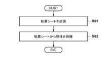
- An example of a method for separating an object from an adhesive sheet is described below with reference to FIG. 6.
- the adhesive sheet holding the object on the adhesive layer is expanded in the surface direction.
- the expansion rate of the adhesive sheet may be 1% or more, or 5% or more, or 20% or less, or 15% or less.
- the adhesive sheet may be expanded in one direction, two or more directions, or in all directions.
- a method for expanding the adhesive sheet in all directions a method using a stage (e.g., a circular stage) and a frame (e.g., a circular frame) larger than the stage can be mentioned. In this case, the adhesive sheet can be fixed to the frame. Then, the frame can be pressed down while the adhesive sheet is placed on the stage. By such a method, the adhesive sheet is expanded in all directions.
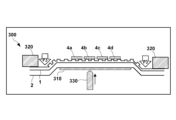
- Figs. 7A and 7B show an expanding device 300 used for expanding an adhesive sheet including an adhesive layer 1 and a base material 2 in a planar direction.
- Fig. 7A shows a state in which an adhesive sheet installed on a base 310 of the expanding device 300 holds objects 4a to 4d.
- the expanding device 300 includes a base 310 for holding an adhesive sheet as the above-mentioned stage.
- the base 310 may be, for example, mesh-shaped or may be ring-shaped with an opening.
- the expanding device 300 also includes a ring frame 320 for supporting the outer periphery of the adhesive sheet as the above-mentioned frame.
- the ring frame 320 may support, for example, a part of the outer periphery of the adhesive sheet, or may support the entire outer periphery of the adhesive sheet.
- Fig. 7B shows a state in which the adhesive sheet is expanded by displacing the ring frame 320 downward.
- the ring frame 320 may be displaced at a speed of, for example, 0.1 mm/sec or more, or at a speed of 1 mm/sec or more.
- the amount of displacement of the ring frame 320 i.e., the amount of pull-down, may be, for example, 1 mm or more, or 5 mm or more. In the state shown in FIG.
- the needle 330 is used to push up the objects 4a to 4d held on the adhesive sheet to apply a physical stimulus. This allows the objects 4a to 4d to be peeled off from the expanded adhesive sheet.
- the method of expanding the adhesive sheet is not limited to this, and may be performed by displacing the ring frame 320 in the surface direction of the adhesive sheet, for example.
- the object is peeled off from the adhesive layer of the adhesive sheet expanded in the surface direction.
- the peeling method is not particularly limited. For example, a method of applying a physical stimulus (e.g., piercing with a needle) to the back surface of the adhesive sheet (the surface opposite to the surface holding the object) can be used. Another method is to irradiate the adhesive sheet with energy rays (e.g., laser light). The object peeled off in this manner can be lifted up using a holding device such as a vacuum chuck and a collet. As described above, the expansion of the adhesive sheet reduces the holding ability of the object by the adhesive sheet.
- a physical stimulus e.g., piercing with a needle
- energy rays e.g., laser light
- the surface peelability of the object on the adhesive sheet after the expansion is improved compared to before the expansion. This makes it easier to peel off the object from the adhesive sheet.
- the object is lifted off from the adhesive sheet without applying a physical stimulus to the back surface of the adhesive sheet or irradiating it with energy rays.
- Example 1 A pressure-sensitive adhesive composition was prepared by dissolving 100 parts by mass of energy ray curable resin (A1), 50 parts by mass of energy ray curable resin (A2), 3 parts by mass of photopolymerization initiator (C1), and 3 parts by mass of antioxidant (E1) in toluene.
- This pressure-sensitive adhesive composition was applied onto the release-treated surface of a release sheet (manufactured by Lintec Corporation, product name: SP-PET381130, a polyethylene terephthalate film laminated with a silicone-based release agent, thickness 38 ⁇ m), and the resulting coating was dried at 100 ° C. for 2 minutes to form a 25 ⁇ m thick adhesive layer.
- a release sheet manufactured by Lintec Corporation, product name: SP-PET381130, a polyethylene terephthalate film laminated with a silicone-based release agent, thickness 38 ⁇ m
- a non-embossed surface of an EMAA substrate (ethylene-methacrylic acid copolymer film, acid content 9% by mass, one surface embossed to give a matte finish, thickness: 80 ⁇ m, breaking elongation 490%) was attached onto this adhesive layer to prepare a pressure-sensitive adhesive sheet.
- EMAA substrate ethylene-methacrylic acid copolymer film, acid content 9% by mass, one surface embossed to give a matte finish, thickness: 80 ⁇ m, breaking elongation 490%
- the adhesive layer of the adhesive sheet was attached to a replica mold on which a concave shape had been formed in advance, and vacuum laminated for 300 seconds at 60° C.
- an ultraviolet irradiator manufactured by Heraeus
- the surface of the adhesive layer of the adhesive sheet is formed with unevenness having convex portions of different heights, as in FIG. 1.
- the convex portions of different heights are cylindrical as in FIG. 4, and are arranged in a lattice pattern with concave portions interposed therebetween.
- the convex portions of different heights function as holding portions.
- the convex portions consisted of first convex portions with a first height H1 of 8 ⁇ m and second convex portions with a second height H2 of 4 ⁇ m.
- the pitch (P) between the first convex portions and the second convex portions in the adhesive sheet was 20 ⁇ m.
- the diameters of the first convex portions and the second convex portions (T1 and T2 shown in FIG. 1) were 8 ⁇ m.
- the ratio of the total area of the first convex portions to the total area of the second convex portions was 100%, and the ratio of the number of the first convex portions to the number of the second convex portions was 100%.
- the ratio of the area of the holding portion between the adhesive layer and the object being held (i.e., the area of the tip surface of each protrusion) to the area of the adhesive sheet is approximately 12.6%.
- Example 2 An adhesive sheet was produced in the same manner as in Example 1, except that a replica mold in which a concave shape different from that in Example 1 was formed was used.
- the surface of the adhesive layer of the adhesive sheet is formed with unevenness having convex portions of different heights, as in FIG. 1.
- the convex portions of different heights are cylindrical as in FIG. 5B, and are arranged in a lattice pattern with concave portions interposed therebetween.
- the convex portions of different heights function as holding portions.
- the convex portions consisted of a first convex portion having a first height H1 of 8 ⁇ m and a second convex portion having a second height H2 of 4 ⁇ m.
- the pitch (P) between the first convex portion and the second convex portion in the adhesive sheet was 20 ⁇ m.
- the diameters of the first convex portion and the second convex portion (T1 and T2 shown in FIG. 1) were 8 ⁇ m.
- the ratio of the total area of the first convex portions to the total area of the second convex portions was 11.1%, and the ratio of the number of the first convex portions to the number of the second convex portions was 11.1%.
- Comparative Example 1 Except for not bonding the replica mold and the adhesive layer, an adhesive sheet was produced in the same manner as in Example 1. In the comparative example, no irregularities were formed on the adhesive layer.
- the substrate used in the examples was cut to 150 mm in MD ⁇ 15 mm in TD to prepare a test sample.
- the tensile modulus of the test sample was measured under an environment of 23°C and 50% RH (relative humidity) in accordance with JIS K 7161-1:2014 and JIS K 7127:1999.
- the above test sample was subjected to a tensile test at a speed of 200 mm/min using a tensile tester (manufactured by Shimadzu Corporation, product name "Autograph (registered trademark) AG-IS 500N") with the chuck distance set to 100 mm, and the tensile modulus (MPa) in the MD direction of the support was measured.
- a tensile tester manufactured by Shimadzu Corporation, product name "Autograph (registered trademark) AG-IS 500N"
- MPa tensile modulus
- MD in MD direction is an abbreviation for Machine Direction, and for example, the MD direction of a substrate means the longitudinal direction when the substrate is manufactured.
- TD in TD direction is an abbreviation for Transverse Direction, and for example, the TD direction of a substrate means the width direction when the substrate is manufactured.
- An adhesive layer was formed from the adhesive composition obtained in each of the Examples and Comparative Examples, and an adhesive layer having a thickness of 1 mm was produced by irradiating the adhesive layer with ultraviolet light at an illuminance of 200 mW/cm 2 and a light quantity of 800 mJ/cm 2 using an ultraviolet irradiator (Heraeus).
- the adhesive layer thus obtained was punched out into a cylindrical shape having a diameter of 8 mm, and the shear storage modulus of the adhesive layer at 23°C was measured by a torsional shear method using a viscoelasticity measuring device (Anton Paar, product name "MCR302") under the conditions of a test start temperature of -60°C, a test end temperature of 150°C, a heating rate of 3.5°C/min, and a frequency of 1 Hz.
- a viscoelasticity measuring device Anton Paar, product name "MCR302”
- the adhesive layer of the adhesive sheet obtained in the example was attached to a ring frame (made of stainless steel), and the adhesive sheet was cut to fit the outer diameter of the ring frame.
- a wafer substrate (mirror silicon wafer, 6 inches, 150 ⁇ m thick) was fixed to a separately prepared dicing tape and diced into 15 mm x 15 mm squares to produce multiple elements (silicon chips, element size 10 mm x 10 mm x 150 ⁇ m).
- the multiple elements obtained were attached to the center of the inner side of the ring frame of the adhesive layer of the adhesive sheet, and the dicing tape was peeled off to transfer the elements from the dicing tape to the adhesive sheet.
- the surface was adjusted so that the mirror surface of the silicon chip was attached to the adhesive layer of the adhesive sheet, and the attachment was performed by laminating at room temperature (23°C), to produce a sample for evaluating surface peelability consisting of an adhesive sheet on which elements were placed and supported by a ring frame.
- A The silicon chip was successfully peeled off more than nine times.
- A The silicon chip was successfully peeled off more than nine times.
Landscapes
- Chemical & Material Sciences (AREA)
- Organic Chemistry (AREA)
- Adhesive Tapes (AREA)
- Adhesives Or Adhesive Processes (AREA)
Priority Applications (3)
| Application Number | Priority Date | Filing Date | Title |
|---|---|---|---|
| JP2024569173A JP7620772B1 (ja) | 2023-03-31 | 2024-03-29 | 粘着シート及び剥離方法 |
| CN202480023212.3A CN120897970A (zh) | 2023-03-31 | 2024-03-29 | 粘着片和剥离方法 |
| KR1020257034779A KR20250169216A (ko) | 2023-03-31 | 2024-03-29 | 점착 시트 및 박리 방법 |
Applications Claiming Priority (2)
| Application Number | Priority Date | Filing Date | Title |
|---|---|---|---|
| JP2023058461 | 2023-03-31 | ||
| JP2023-058461 | 2023-03-31 |
Publications (1)
| Publication Number | Publication Date |
|---|---|
| WO2024204683A1 true WO2024204683A1 (ja) | 2024-10-03 |
Family
ID=92905837
Family Applications (1)
| Application Number | Title | Priority Date | Filing Date |
|---|---|---|---|
| PCT/JP2024/012979 Ceased WO2024204683A1 (ja) | 2023-03-31 | 2024-03-29 | 粘着シート及び剥離方法 |
Country Status (5)
| Country | Link |
|---|---|
| JP (1) | JP7620772B1 (https=) |
| KR (1) | KR20250169216A (https=) |
| CN (1) | CN120897970A (https=) |
| TW (1) | TW202502553A (https=) |
| WO (1) | WO2024204683A1 (https=) |
Citations (7)
| Publication number | Priority date | Publication date | Assignee | Title |
|---|---|---|---|---|
| JP2004115766A (ja) * | 2002-09-30 | 2004-04-15 | Dainippon Printing Co Ltd | 粘着シート |
| JP2006022256A (ja) * | 2004-07-09 | 2006-01-26 | Oji Tac Hanbai Kk | 両面粘着シートおよびその製造方法、積層体 |
| JP2009096816A (ja) * | 2007-10-12 | 2009-05-07 | Lintec Corp | 粘着シート及びその製造方法 |
| KR20160122983A (ko) * | 2015-04-15 | 2016-10-25 | 신화인터텍 주식회사 | 미세구조화된 표면을 갖는 접합 테이프, 이형라이너 및 접합 테이프의 제조방법 |
| WO2020050332A1 (ja) * | 2018-09-07 | 2020-03-12 | リンテック株式会社 | 剥離ライナー、剥離ライナーの作製方法、粘着シート、および粘着シートの作製方法 |
| JP2020061529A (ja) * | 2018-10-12 | 2020-04-16 | 三井化学株式会社 | 電子装置の製造方法および粘着性フィルム |
| WO2024063129A1 (ja) * | 2022-09-22 | 2024-03-28 | リンテック株式会社 | 粘着シート及び剥離方法 |
-
2024
- 2024-03-29 CN CN202480023212.3A patent/CN120897970A/zh active Pending
- 2024-03-29 JP JP2024569173A patent/JP7620772B1/ja active Active
- 2024-03-29 WO PCT/JP2024/012979 patent/WO2024204683A1/ja not_active Ceased
- 2024-03-29 KR KR1020257034779A patent/KR20250169216A/ko active Pending
- 2024-03-29 TW TW113112007A patent/TW202502553A/zh unknown
Patent Citations (7)
| Publication number | Priority date | Publication date | Assignee | Title |
|---|---|---|---|---|
| JP2004115766A (ja) * | 2002-09-30 | 2004-04-15 | Dainippon Printing Co Ltd | 粘着シート |
| JP2006022256A (ja) * | 2004-07-09 | 2006-01-26 | Oji Tac Hanbai Kk | 両面粘着シートおよびその製造方法、積層体 |
| JP2009096816A (ja) * | 2007-10-12 | 2009-05-07 | Lintec Corp | 粘着シート及びその製造方法 |
| KR20160122983A (ko) * | 2015-04-15 | 2016-10-25 | 신화인터텍 주식회사 | 미세구조화된 표면을 갖는 접합 테이프, 이형라이너 및 접합 테이프의 제조방법 |
| WO2020050332A1 (ja) * | 2018-09-07 | 2020-03-12 | リンテック株式会社 | 剥離ライナー、剥離ライナーの作製方法、粘着シート、および粘着シートの作製方法 |
| JP2020061529A (ja) * | 2018-10-12 | 2020-04-16 | 三井化学株式会社 | 電子装置の製造方法および粘着性フィルム |
| WO2024063129A1 (ja) * | 2022-09-22 | 2024-03-28 | リンテック株式会社 | 粘着シート及び剥離方法 |
Also Published As
| Publication number | Publication date |
|---|---|
| CN120897970A (zh) | 2025-11-04 |
| TW202502553A (zh) | 2025-01-16 |
| KR20250169216A (ko) | 2025-12-02 |
| JPWO2024204683A1 (https=) | 2024-10-03 |
| JP7620772B1 (ja) | 2025-01-23 |
Similar Documents
| Publication | Publication Date | Title |
|---|---|---|
| JP5268575B2 (ja) | ダイシング・ダイボンディングテープの製造方法 | |
| TWI657550B (zh) | Extensible sheet and method for manufacturing laminated wafer | |
| JP7680640B2 (ja) | 素子転写用シート | |
| CN104303271A (zh) | 切割片 | |
| CN106795396A (zh) | 粘着片以及加工物的制造方法 | |
| JP2015156438A (ja) | 半導体チップの製造方法 | |
| JP7620772B1 (ja) | 粘着シート及び剥離方法 | |
| US20250215276A1 (en) | Adhesive sheet and method for manufacturing electronic component or semiconductor device | |
| JP2011199008A (ja) | 粘接着シート、ダイシング−ダイボンディングテープ及び粘接着シート付き半導体チップの製造方法 | |
| TWI893277B (zh) | 黏著片材 | |
| TWI803567B (zh) | 長條積層片及其捲料 | |
| WO2026088902A1 (ja) | 電子部品貼付用粘着シート | |
| WO2020175363A1 (ja) | 裏面研削用粘着シート及び半導体ウエハの製造方法 | |
| WO2026088901A1 (ja) | 電子部品製造方法及び電子部品加工装置 | |
| TWI461498B (zh) | Cut sticky ribbon | |
| WO2025063123A1 (ja) | 粘着シート及び物体の取り扱い方法 | |
| WO2025063125A1 (ja) | 粘着シート及び物体の取り扱い方法 | |
| WO2025063124A1 (ja) | 粘着シート及び物体の取り扱い方法 | |
| JP2013065625A (ja) | ダイシング−ダイボンディングテープ、粘接着剤層付き半導体チップの作製キット及び粘接着剤層付き半導体チップの製造方法 | |
| JP2014060201A (ja) | ダイシング−ダイボンディングテープ及び粘接着剤層付き半導体チップの製造方法 | |
| WO2025205831A1 (ja) | 半導体加工用テープ | |
| JP2013207032A (ja) | ダイシング−ダイボンディングテープ及び粘接着剤層付き半導体チップの製造方法 |
Legal Events
| Date | Code | Title | Description |
|---|---|---|---|
| 121 | Ep: the epo has been informed by wipo that ep was designated in this application |
Ref document number: 24780778 Country of ref document: EP Kind code of ref document: A1 |
|
| WWE | Wipo information: entry into national phase |
Ref document number: 2024569173 Country of ref document: JP |
|
| WWE | Wipo information: entry into national phase |
Ref document number: 202480023212.3 Country of ref document: CN |
|
| ENP | Entry into the national phase |
Ref document number: 1020257034779 Country of ref document: KR Free format text: ST27 STATUS EVENT CODE: A-0-1-A10-A15-NAP-PA0105 (AS PROVIDED BY THE NATIONAL OFFICE) |
|
| WWE | Wipo information: entry into national phase |
Ref document number: KR1020257034779 Country of ref document: KR |
|
| NENP | Non-entry into the national phase |
Ref country code: DE |
|
| WWP | Wipo information: published in national office |
Ref document number: 202480023212.3 Country of ref document: CN |
|
| 122 | Ep: pct application non-entry in european phase |
Ref document number: 24780778 Country of ref document: EP Kind code of ref document: A1 |