WO2024204464A1 - 吸収性物品に用いる吸収性シートの製造方法及び製造装置 - Google Patents
吸収性物品に用いる吸収性シートの製造方法及び製造装置 Download PDFInfo
- Publication number
- WO2024204464A1 WO2024204464A1 PCT/JP2024/012498 JP2024012498W WO2024204464A1 WO 2024204464 A1 WO2024204464 A1 WO 2024204464A1 JP 2024012498 W JP2024012498 W JP 2024012498W WO 2024204464 A1 WO2024204464 A1 WO 2024204464A1
- Authority
- WO
- WIPO (PCT)
- Prior art keywords
- sheet
- composite sheet
- absorbent
- roll
- continuous
- Prior art date
- Legal status (The legal status is an assumption and is not a legal conclusion. Google has not performed a legal analysis and makes no representation as to the accuracy of the status listed.)
- Ceased
Links
Images


Classifications
-
- A—HUMAN NECESSITIES
- A61—MEDICAL OR VETERINARY SCIENCE; HYGIENE
- A61F—FILTERS IMPLANTABLE INTO BLOOD VESSELS; PROSTHESES; DEVICES PROVIDING PATENCY TO, OR PREVENTING COLLAPSING OF, TUBULAR STRUCTURES OF THE BODY, e.g. STENTS; ORTHOPAEDIC, NURSING OR CONTRACEPTIVE DEVICES; FOMENTATION; TREATMENT OR PROTECTION OF EYES OR EARS; BANDAGES, DRESSINGS OR ABSORBENT PADS; FIRST-AID KITS
- A61F13/00—Bandages or dressings; Absorbent pads
- A61F13/15—Absorbent pads, e.g. sanitary towels, swabs or tampons for external or internal application to the body; Supporting or fastening means therefor; Tampon applicators
- A61F13/15577—Apparatus or processes for manufacturing
- A61F13/15804—Plant, e.g. involving several steps
-
- A—HUMAN NECESSITIES
- A61—MEDICAL OR VETERINARY SCIENCE; HYGIENE
- A61F—FILTERS IMPLANTABLE INTO BLOOD VESSELS; PROSTHESES; DEVICES PROVIDING PATENCY TO, OR PREVENTING COLLAPSING OF, TUBULAR STRUCTURES OF THE BODY, e.g. STENTS; ORTHOPAEDIC, NURSING OR CONTRACEPTIVE DEVICES; FOMENTATION; TREATMENT OR PROTECTION OF EYES OR EARS; BANDAGES, DRESSINGS OR ABSORBENT PADS; FIRST-AID KITS
- A61F13/00—Bandages or dressings; Absorbent pads
- A61F13/15—Absorbent pads, e.g. sanitary towels, swabs or tampons for external or internal application to the body; Supporting or fastening means therefor; Tampon applicators
- A61F13/15577—Apparatus or processes for manufacturing
- A61F13/15707—Mechanical treatment, e.g. notching, twisting, compressing, shaping
-
- A—HUMAN NECESSITIES
- A61—MEDICAL OR VETERINARY SCIENCE; HYGIENE
- A61F—FILTERS IMPLANTABLE INTO BLOOD VESSELS; PROSTHESES; DEVICES PROVIDING PATENCY TO, OR PREVENTING COLLAPSING OF, TUBULAR STRUCTURES OF THE BODY, e.g. STENTS; ORTHOPAEDIC, NURSING OR CONTRACEPTIVE DEVICES; FOMENTATION; TREATMENT OR PROTECTION OF EYES OR EARS; BANDAGES, DRESSINGS OR ABSORBENT PADS; FIRST-AID KITS
- A61F13/00—Bandages or dressings; Absorbent pads
- A61F13/15—Absorbent pads, e.g. sanitary towels, swabs or tampons for external or internal application to the body; Supporting or fastening means therefor; Tampon applicators
- A61F13/15577—Apparatus or processes for manufacturing
- A61F13/15764—Transferring, feeding or handling devices; Drives
Definitions
- the present invention relates to a method and device for manufacturing an absorbent sheet for use in absorbent articles, and more specifically, to a technology for manufacturing an absorbent sheet in which absorbent material is arranged in two layers.
- Absorbent articles such as disposable diapers have absorbents arranged to absorb and retain liquids.
- the absorbent consists of absorbent material such as powder or granular SAP (Super Absorbent Polymer) arranged between sheets of nonwoven fabric or the like.
- Such an absorbent body is formed by cutting an absorbent sheet.
- a first continuous sheet 201 is conveyed by a conveyor 150, SAP is supplied from an SAP supplying device 140 onto the first continuous sheet 201, a second continuous sheet 202 is then superimposed and joined onto the first continuous sheet 201 to which SAP has been supplied, and the first and second continuous sheets 201, 202 joined together are then compressed using a compression device 170 to form an absorbent sheet.
- the SAP supplying device 140 is configured so that an opening for supplying SAP opens and closes at appropriate times (see, for example, Patent Document 1).
- the variety of absorbent bodies can be increased by appropriately combining the types, amounts, and arrangement patterns of absorbent materials placed in the absorbent body. By arranging the absorbent material in two layers and changing the combinations of the types, amounts, and arrangement patterns of absorbent materials in each layer, the variety can be further increased.
- the problem that the present invention aims to solve is to provide a manufacturing method and manufacturing device for an absorbent sheet used in an absorbent article, which can reduce the manufacturing cost of an absorbent sheet in which absorbent materials are arranged in two layers.
- the present invention provides a method for manufacturing an absorbent sheet for use in an absorbent article configured as follows.
- a method for manufacturing an absorbent sheet for use in absorbent articles includes: (i) a first step of winding a first continuous sheet around a rotating first transport roll and transporting the sheet; (ii) a second step of supplying a first absorbent material to the first continuous sheet being wound around the first transport roll and transported; (iii) a third step of overlapping a second continuous sheet on the first continuous sheet so as to cover the first absorbent material supplied to the first continuous sheet, thereby forming a first composite sheet in which the first absorbent material is sandwiched between the first continuous sheet and the second continuous sheet; and (iv) a fourth step of winding the first composite sheet around a rotating second transport roll and transporting the sheet.
- an absorbent sheet having absorbent material arranged in two layers can be manufactured using three continuous sheets, which is one less continuous sheet than when an absorbent sheet having absorbent material arranged in two layers is manufactured using four continuous sheets. Therefore, the manufacturing cost of an absorbent sheet having absorbent material arranged in two layers can be reduced.
- the first composite sheet is transported by supporting the first composite sheet on a first support surface and moving the first support surface while being sucked to the first support surface.
- the first absorbent material in the first composite sheet is prevented from being displaced in the planar direction even when the first composite sheet is transported at high speed. This makes it possible to improve production efficiency by increasing the transport speed.
- the device for manufacturing the first composite sheet and the device for manufacturing the second composite sheet can be arranged with a gap between them, making it easy to simplify and standardize the device configuration.
- the first composite sheet is wrapped around and supported by a first reversing roll that is disposed adjacent to the first conveying roll and rotates in the opposite direction to the first conveying roll and is conveyed.
- the pressure between the first and second continuous sheets of the first composite sheet is strengthened, and the movement of the first absorbent material in the first composite sheet in the planar direction can be suppressed.
- the first composite sheet discharged from the first reversing roll is supported horizontally and transported horizontally using a first conveyor, and the first composite sheet is supplied to the second transport roll.
- the movement of the first absorbent material in the first composite sheet in the planar direction can be suppressed in the section from the first reversing roll to the second transport roll.
- the second composite sheet is transported by supporting the second composite sheet on a second support surface and moving the second support surface while being sucked to the second support surface.
- the first and second absorbent materials in the second composite sheet are prevented from being displaced in the planar direction even when the second composite sheet is transported at high speed. Therefore, it is possible to improve production efficiency by increasing the transport speed.
- the device for manufacturing the second composite sheet and the press device can be arranged with a gap between them.
- the second composite sheet is wrapped around and supported by a second reversing roll that is disposed adjacent to the second transport roll and rotates in the opposite direction to the second transport roll, and is transported.
- the second composite sheet discharged from the second reversing roll is supported horizontally and transported horizontally using a second conveyor, and the second composite sheet is supplied to the press device.
- the movement of the first and second absorbent materials in the second composite sheet in the planar direction can be suppressed in the section from the second reversing roll to the second transport roll.
- the first composite sheet that is wrapped around and transported around the first reversing roll is pressed toward the first reversing roll by a first belt and/or a first press roll.
- the second composite sheet that is wrapped around and transported around the second reversing roll is pressed toward the second reversing roll by a second belt and/or a second press roll.
- the second composite sheet is compressed in the thickness direction using the second belt and/or the second press roll and the second reversing roll as the press device.
- the present invention also provides a manufacturing device for an absorbent sheet used in an absorbent article, configured as follows:
- the manufacturing device for an absorbent sheet used in an absorbent article includes: (a) a first composite sheet forming device that receives a first continuous sheet and a second continuous sheet and forms a first composite sheet in which a first absorbent material is disposed between the first continuous sheet and the second continuous sheet; (b) a second composite sheet forming device that receives a first composite sheet and a third continuous sheet and forms a second composite sheet in which a second absorbent material is disposed between the first composite sheet and the third continuous sheet; and (c) a press device that compresses the second composite sheet in the thickness direction.
- an absorbent sheet having absorbent material arranged in two layers can be manufactured using three continuous sheets, which is one less continuous sheet compared to when an absorbent sheet having absorbent material arranged in two layers is manufactured using four continuous sheets. Therefore, the manufacturing cost of an absorbent sheet having absorbent material arranged in two layers can be reduced.
- the absorbent sheet manufacturing device further includes (d) a first conveyor disposed between the first composite sheet forming device and the second composite sheet forming device, having a first transport surface that supports and moves while sucking the first composite sheet, and transports the first composite sheet toward the second composite sheet forming device.
- a first conveyor disposed between the first composite sheet forming device and the second composite sheet forming device, having a first transport surface that supports and moves while sucking the first composite sheet, and transports the first composite sheet toward the second composite sheet forming device.
- the first absorbent material in the first composite sheet being transported by the first conveyor is prevented from being displaced in the planar direction even when the first composite sheet is transported at high speed. This makes it possible to improve production efficiency by increasing the transport speed.
- the first composite sheet forming device and the second composite sheet forming device can be arranged with a gap between them, making it easy to simplify and standardize the configuration of the first composite sheet forming device and the second composite sheet forming device.
- the first composite sheet forming device includes (i) a first conveying roll around which the first continuous sheet is wound and which conveys the first continuous sheet; (ii) a first absorbent material supplying device which supplies the first absorbent material to the first continuous sheet wound around the first conveying roll and conveyed; (iii) a first guide roll which guides the second continuous sheet to form the first composite sheet by overlapping the second continuous sheet on the first continuous sheet so as to cover the first absorbent material supplied to the first continuous sheet; and (iv) a first reversing roll which is disposed adjacent to the first conveying roll, around which the first composite sheet is wound to support the second continuous sheet of the first composite sheet, and which rotates in the opposite direction to the first conveying roll to convey the first composite sheet, and is configured so that the first composite sheet is sucked onto a first support surface on which the first composite sheet is supported.
- the movement of the first absorbent material in the first composite sheet in the planar direction can be suppressed, and the production efficiency can be improved by increasing the conveying speed.
- the first composite sheet forming device can be made smaller than when the first continuous sheet is conveyed along a linear path.
- the absorbent sheet manufacturing device further includes (e) a second conveyor that is disposed between the second composite sheet forming device and the press device, has a second transport surface that supports and moves while sucking the second composite sheet, and transports the second composite sheet.
- the first and second absorbent materials in the second composite sheet being transported by the second conveyor are prevented from being displaced in the planar direction even when the second composite sheet is transported at high speed. This makes it possible to improve production efficiency by increasing the transport speed.
- the second composite sheet forming device and the press device can be arranged with a gap between them, making it easy to simplify and standardize the device configuration.
- the second composite sheet forming device includes (i) a second transport roll around which the first composite sheet is wound and which transports the second composite sheet; (ii) a second absorbent material supplying device which supplies the second absorbent material to the first composite sheet wound around the second transport roll and transported; (iii) a second guide roll which guides the third continuous sheet to form the second composite sheet by overlapping the third continuous sheet on the first composite sheet so as to cover the second absorbent material supplied to the second composite sheet; and (iv) a second reversing roll which is disposed adjacent to the second transport roll, around which the second composite sheet is wound to support the third continuous sheet of the second composite sheet, and which rotates in the opposite direction to the first transport roll to transport the second composite sheet, and is configured so that the second composite sheet is sucked onto the second support surface on which the second composite sheet is supported.
- the movement of the first and second absorbent materials in the second composite sheet in the planar direction can be suppressed, and the production efficiency can be improved by increasing the conveying speed.
- the second composite sheet forming device can be made smaller than when the second composite sheet is conveyed along a linear path.
- the absorbent sheet manufacturing device further includes a first belt and/or a first press roll that is disposed opposite the first reversing roll and presses the first composite sheet, which is wound around and transported around the first reversing roll, toward the first reversing roll.
- a first belt and/or a first press roll that is disposed opposite the first reversing roll and presses the first composite sheet, which is wound around and transported around the first reversing roll, toward the first reversing roll.
- the absorbent sheet manufacturing device further includes a second belt and/or a second press roll that is disposed opposite the second reversing roll and presses the second composite sheet, which is wound around and transported around the second reversing roll, toward the second reversing roll.
- a second belt and/or a second press roll that is disposed opposite the second reversing roll and presses the second composite sheet, which is wound around and transported around the second reversing roll, toward the second reversing roll.
- the second belt and/or the second press roll and the second reversing roll are configured as the press device that compresses the second composite sheet in the thickness direction.
- the configuration of the absorbent sheet manufacturing device can be simplified.
- the present invention reduces the manufacturing costs of absorbent sheets in which absorbent materials are arranged in two layers.
- FIG. 1 is a schematic diagram showing the overall configuration of an absorbent sheet manufacturing apparatus.
- FIG. 2 is an enlarged schematic diagram showing the main components of an absorbent sheet manufacturing apparatus.
- FIG. 3 is an enlarged schematic diagram showing the main components of an absorbent sheet manufacturing apparatus.
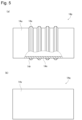
- Fig. 4(a) is a schematic exploded cross-sectional view of the absorbent body
- Fig. 4(b) is a plan view taken along line BB in Fig. 4(a)
- Fig. 4(c) is a plan view taken along line CC in Fig. 4(a).
- Fig. 5(a) is a schematic partial cross-sectional side view of the first press roll on the upstream side
- Fig. 5(b) is a schematic side view of the first press roll on the downstream side.
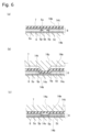
- FIG. 6 is a schematic cross-sectional view of a second composite sheet in the width direction.
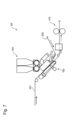
- FIG. 7 is a schematic diagram of an absorbent sheet manufacturing device.
- Example 1 The absorbent sheet manufacturing apparatus and manufacturing device of Example 1 will be described with reference to Figures 1 to 4.
- Figure 1 is a schematic diagram showing the overall configuration of the absorbent sheet manufacturing apparatus 10.
- Figures 2 and 3 are enlarged schematic diagrams showing the main components of the absorbent sheet manufacturing apparatus 10.
- the absorbent sheet manufacturing device 10 includes a first composite sheet forming device 12, a first conveyor 13, a second composite sheet forming device 14, a second conveyor 15, and a press device 16.
- the first composite sheet forming device 12 supplies first and second continuous sheets 2, 4 such as nonwoven fabric in the directions indicated by arrows 2f, 4f, forming a first composite sheet 7 in which a first absorbent material 3 such as granular or powdered SAP (see FIG. 4(a)) is disposed between the first continuous sheet 2 and the second continuous sheet 4.
- first and second continuous sheets 2, 4 such as nonwoven fabric in the directions indicated by arrows 2f, 4f, forming a first composite sheet 7 in which a first absorbent material 3 such as granular or powdered SAP (see FIG. 4(a)) is disposed between the first continuous sheet 2 and the second continuous sheet 4.
- the first composite sheet forming device 12 has a first SAP supply device 12d, a first guide roll 12c, and a first reversing roll 12b arranged around a first transport roll 12a.
- the first transport roll 12a has a cylindrical outer peripheral surface 12s around which the first continuous sheet 2 is wound, and rotates in the direction indicated by the arrow 12f to transport the first continuous sheet 2.
- the first SAP supply device 12d has an opening 12e facing the first continuous sheet 2 wound around the first transport roll 12a, and is configured so that the first absorbent material 3 falls from the opening 12e.
- the opening 12e opens and closes at appropriate times, thereby supplying the first absorbent material 3 so that it is positioned in a specified area on the first continuous sheet 2 wound around and transported around the first transport roll 12a.
- the first guide roll 12c guides the second continuous sheet 4 so that it overlaps the first continuous sheet 2 to which the first absorbent material 3 has been supplied and covers the first absorbent material 3. This forms the first composite sheet 7.
- the first reversing roll 12b is disposed adjacent to the first transport roll 12a, and the first composite sheet 7 is wound around it so as to support the second continuous sheet 4 of the first composite sheet 7.
- the first reversing roll 12b rotates in the opposite direction to the first transport roll 12a as indicated by the arrow 12g, transporting the first composite sheet 7.
- the outer peripheral surface 12s of the first transport roll 12a and the outer peripheral surface 12t of the first reversing roll 12b are the first support surfaces 12s, 12t that support the first composite sheet 7 and are configured to suck the first composite sheet 7.
- first suction boxes 12u, 12v connected to a vacuum source or reduced pressure source are arranged inside the first transport roll 12a and inside the first reversing roll 12b, and through holes (not shown) communicating with the first suction boxes 12u, 12v are formed in the first support surfaces 12s, 12t, and the first composite sheet 7 is sucked onto the first support surfaces 12s, 12t by air flow in the directions indicated by the arrows 15u, 15v.
- the first absorbent material 3 in the first composite sheet 7 is prevented from becoming disorganized in the planar direction even when the first composite sheet 7 is transported at high speed. This makes it possible to increase the transport speed and improve the production efficiency of the absorbent sheet 9.
- a first belt 12m may be arranged around the first reversing roll 12b so as to be movable along the first reversing roll 12b, and the first composite sheet 7 may be transported while being sandwiched between the first reversing roll 12b and the first belt 12m.
- the pressure between the first continuous sheet 2 and the second continuous sheet 4 of the first composite sheet 7 is strengthened, and the movement of the first absorbent material 3 in the first composite sheet 7 in the planar direction can be further suppressed.
- the first belt 12m may be non-breathable, or may be breathable to the extent that it is sucked into the first reversing roll 12b.
- first press rolls 12p, 12q may be arranged to face the first reversing roll 12b, and the first composite sheet 7 wound around the first reversing roll 12b and transported may be pressed toward the first reversing roll 12b by the first press rolls 12p, 12q.
- the number of first press rolls 12p, 12q may be one or three or more.
- the first press rolls 12p, 12q are arranged together with the first belt 12m, the first press rolls 12p, 12q are configured to press the first composite sheet 7 toward the first reversing roll 12b via the first belt 12m.
- first press rolls 12p, 12q By providing the first press rolls 12p, 12q, it is possible to suppress the misalignment between the first continuous sheet 2 and the second continuous sheet 4 of the first composite sheet 7, and further suppress the movement of the first absorbent material 3 in the first composite sheet 7 in the planar direction.
- the first conveyor 13 is disposed between the first composite sheet forming device 12 and the second composite sheet forming device 14, and transports the first composite sheet 7 discharged from the first reversing roll 12b of the first composite sheet forming device 12 toward the second composite sheet forming device 14.
- the first conveyor 13 is configured such that a breathable first endless belt 13b moves in a circulating manner, and a third suction box 13k connected to a vacuum source or reduced pressure source is disposed inside the first endless belt 13b, and is configured such that the first composite sheet 7 is sucked onto the upper surface 13a of the first endless belt 13b by air flow in the direction indicated by arrow 15W.
- the upper surface 13a of the first endless belt 13b is the first transport surface 13a that horizontally supports and sucks the first composite sheet 7 while moving horizontally.
- the second composite sheet forming device 14 receives the first composite sheet 7 discharged from the first conveyor 13 in the direction indicated by the arrow 7x, and a third continuous sheet 6 such as a nonwoven fabric, and forms a second composite sheet 8 in which a second absorbent material 5 such as granular or powdered SAP (see FIG. 4(a)) is disposed between the first composite sheet 7 and the third continuous sheet 6.
- a second absorbent material 5 such as granular or powdered SAP (see FIG. 4(a)) is disposed between the first composite sheet 7 and the third continuous sheet 6.
- the second composite sheet forming device 14 has the same configuration as the first composite sheet forming device 12, and a second SAP supply device 14d, a second guide roll 14c, and a second reversing roll 14b are arranged around the second transport roll 14a.
- Second suction boxes 14u, 14v are arranged inside the second transport roll 14a and the second reversing roll 14b, and are configured to suck the second composite sheet 8 onto the second support surfaces 14s, 14t of the second transport roll 14a and the second reversing roll 14b by air flows in the directions indicated by the arrows 17u, 17v.
- a second belt 14m may be arranged around the second reversing roll 14b in a manner similar to the first reversing roll 12b so as to be movable along the second reversing roll 14b, and the second composite sheet 8 may be conveyed while being sandwiched between the second reversing roll 14b and the second belt 14m.
- the pressure between the first composite sheet 7 and the third continuous sheet 6 of the second composite sheet 8 is strengthened, and the movement of the second absorbent material 5 in the second composite sheet 8 in the planar direction can be further suppressed.
- the second belt 14m may be non-breathable or may be breathable to the extent that it is sucked into the second reversing roll 14b.
- second press rolls 14p, 14q may be arranged to face the second reversing roll 14b to press the second composite sheet 8 toward the second reversing roll 14b. In this case, the movement of the second absorbent material 5 in the second composite sheet 8 in the planar direction can be further suppressed.
- the number of second press rolls 14p, 14q may be one, or three or more.
- the second composite sheet 8 discharged from the second reversing roll 14b of the second composite sheet forming device 14 is transported by the second conveyor 15 toward the press device 16.
- the second conveyor 15 has the same configuration as the first conveyor 13, and includes a second endless belt 15b that is breathable and moves in a circular motion.
- a fourth suction box 15k connected to a vacuum source or reduced pressure source is disposed inside the second endless belt 15b, and is configured to suck the second composite sheet 8 onto the upper surface 15a of the second endless belt 15b, i.e., the second transport surface 15a.
- the second composite sheet 8 discharged from the second conveyor 15 in the direction indicated by the arrow 8x is compressed in the thickness direction as it passes between the pair of rolls 16a, 16b of the press device 16. This forms the absorbent sheet 9.
- the absorbent sheet 9 is cut to a predetermined size in a later process to form individual pieces of absorbent body 8k, for example, as shown in FIG. 4.
- the absorbent body 8k is placed in an absorbent article such as a disposable diaper or sanitary napkin.
- FIG. 4(a) is a schematic exploded cross-sectional view of absorbent body 8k.
- FIG. 4(b) is a plan view taken along line B-B in FIG. 4(a).
- FIG. 4(c) is a plan view taken along line C-C in FIG. 4(a).
- a first absorbent material 3 is disposed on one main surface 2a of a first sheet 2k formed from a first continuous sheet 2, and a second absorbent material 5 is disposed on the other main surface 2b of the first sheet 2k.
- the first absorbent material 3 is sandwiched between the first sheet 2k and a second sheet 4k formed from a second continuous sheet 4.
- the second absorbent material 5 is sandwiched between the first sheet 2k and a third sheet 6k formed from a third continuous sheet 6. That is, the first absorbent material 3 is disposed in a first layer between the first sheet 2k and the second sheet 4k, and the second absorbent material 5 is disposed in a second layer between the first sheet 2k and the third sheet 6k.
- the first and second absorbent materials 3, 5 can be disposed in various patterns.
- the first absorbent material 3 is arranged in two regions 3a and 3b on both sides in the longitudinal direction
- the second absorbent material 5 is arranged in three regions 5a, 5b, and 5c at the longitudinal center, spaced apart from each other and extending in the longitudinal direction.
- an absorbent sheet 9 having absorbent materials 3 and 5 arranged in two layers can be manufactured using three continuous sheets 2, 4, and 6.
- the first absorbent material 3 in the first composite sheet 7 during transport is prevented from becoming disorganized in the planar direction even when the first composite sheet 7 is transported at high speed. This makes it possible to improve production efficiency by increasing the transport speed.
- the first composite sheet forming device 12 and the second composite sheet forming device 14 can be arranged with a gap between them, making it easy to simplify and standardize the configuration of the first composite sheet forming device 12 and the second composite sheet forming device 14.
- the first and second absorbent materials 3, 5 in the second composite sheet 8 during transport are prevented from becoming disorganized in the planar direction even when the second composite sheet 8 is transported at high speed. This makes it possible to improve production efficiency by increasing the transport speed.
- the second composite sheet forming device 14 and the press device 16 can be arranged with a gap between them.
- the first composite sheet forming device 12 is composed of a first transport roll 12a, a first reversing roll 12b, etc., and transports the first composite sheet 7 while sucking it against the first support surfaces 12s, 12t. This makes it possible to suppress the movement of the first absorbent material 3 in the first composite sheet 7 in the planar direction, and to improve production efficiency by speeding up transport.
- the first composite sheet forming device 12 can be made smaller than when the first composite sheet 7 is transported along a linear path.
- the second composite sheet forming device 14 is composed of a second transport roll 14a, a second reversing roll 14b, etc., and the second composite sheet 8 is transported while being sucked onto the second support surfaces 14s, 14t, the movement of the first and second absorbent materials 3, 5 in the second composite sheet 8 in the planar direction can be suppressed, and the production efficiency can be improved by increasing the transport speed. Also, the second composite sheet forming device 14 can be made smaller than when the second composite sheet 8 is transported along a linear path.
- first press rolls 12p, 12q and the second press rolls 14p, 14q will be described in more detail.
- Figure 5(a) is a schematic partial cross-sectional side view of the upstream second press roll 14p.
- the upstream second press roll 14p has four circumferentially extending ridges 14x formed on the cylindrical outer circumferential surface 14u.
- the upstream second press roll 14p has an outer circumferential member 14n to which an elongated member 14r for forming the ridges 14x is fixed by welding or the like.
- Figure 5(b) is a schematic side view of the downstream second press roll 14q. As shown in Figure 5(b), the downstream second press roll 14q has a cylindrical outer peripheral surface 14v, and no protrusions or ridges are formed on the outer peripheral surface 14v.
- FIG. 6 is a schematic cross-sectional view of the second composite sheet 8 when compressed by the second press rolls 14p and 14q.
- the second composite sheet 8 is sandwiched between the second support surface 14t of the second reversing roll 14b and the second belt 14m.
- the ridges 14x of the upstream second press roll 14p press the area 5k (see FIG. 6(a)) adjacent to the areas 5s and 5t in which the second absorbent material 5 is arranged. This causes the second absorbent materials 5p and 5q arranged near the boundary between the areas 5s and 5t to be compressed.
- the second absorbent material 5p, 5q arranged near the boundary between the regions 5s, 5t does not move toward the outside of the regions 5s, 5t, so that a well-shaped slit (long, narrow gap) can be formed between the regions 5s, 5t where the second absorbent material 5 is arranged.
- the second absorbent material 5p, 5q arranged in the vicinity of the boundary between the regions 5s, 5t will move toward the outside of the regions 5s, 5t as shown by the arrows 5x, and the width of the slits will tend to become narrower and the shape of the slits will tend to become distorted.
- the second absorbent material 5p, 5q arranged in the vicinity of the boundary between the regions 5s, 5t is compressed in advance using the second press roll 14p on the upstream side, when the entire width is pressed using the second press roll 14q on the downstream side, the second absorbent material 5p, 5q in the vicinity of the boundary between the regions 5s, 5t will not move toward the outside of the regions 5s, 5t. As a result, a slit with a good shape can be formed.
- the upstream second press roll 14p is used to form the slits
- the downstream second press roll 14q is used to press the entire second composite sheet 8 after the slits have been formed.
- FIG. 5(b) illustrates a case in which the outer peripheral surface 14u of the upstream second press roll 14p does not press against the second belt 14m, but the outer peripheral surface 14u of the upstream second press roll 14p may press against the regions 14s and 14t of the second composite sheet 8 via the second belt 14m.
- the upstream first press roll 12p forms widthwise extending ridges at intervals in the circumferential direction on the cylindrical outer circumferential surface of the upstream first press roll 12p so as to press the areas near the boundary line between the regions 3a, 3b, and/or forms circumferentially extending ridges at intervals in the axial direction on the outer circumferential surface of the upstream first press roll 12p so as to press the areas near the boundary line on both sides in the width direction of the regions 3a, 3b.
- the downstream first press roll 12q like the downstream second press roll 14q, does not have ridges or protrusions formed on its cylindrical outer circumferential surface.
- first press rolls 12p, 12q may be configured similarly to the second press rolls 14p, 14q, with the upstream first press roll 12p being used to form the slits and the downstream first press roll 12q being used to press the entire first composite sheet 7 after the slits have been formed.
- the method for manufacturing the absorbent sheet 9 includes steps 1 to 7.
- the first continuous sheet 2 is wrapped around the rotating first transport roll 12a of the first composite sheet forming device 12 and transported.
- the first SAP supplying device 12d of the first composite sheet forming device 12 supplies the first absorbent material 3 to the first continuous sheet 2 that is wound around and transported by the first transport roll 12a.
- the first guide roll 12c of the first composite sheet forming device 12 overlays the second continuous sheet 4 on the first continuous sheet 2 so as to cover the first absorbent material 3 supplied to the first continuous sheet 2, forming a first composite sheet 7 in which the first absorbent material 3 is sandwiched between the first continuous sheet 2 and the second continuous sheet 4.
- the first composite sheet 7 is wound around the rotating second transport roll 14a of the second composite sheet forming device 14 and transported.
- the second SAP supplying device 14d of the second composite sheet forming device 14 supplies the second absorbent material 5 to the first composite sheet 7 that is wound around and transported by the second transport roll 14a.
- the second guide roll 14c of the second composite sheet forming device 14 overlays the third continuous sheet 6 on the first composite sheet 7 so as to cover the second absorbent material 5 supplied to the first composite sheet 7, forming a second composite sheet 8 in which the first absorbent material 3 is sandwiched between the first continuous sheet 2 and the second continuous sheet 4, and the second SAP 4 is sandwiched between the second continuous sheet 4 and the third continuous sheet 6.
- the second composite sheet 8 is compressed in the thickness direction using a press device 16 to form an absorbent sheet 9.
- the first composite sheet 7 is supported by the first support surfaces 12s, 12t and transported by moving the first support surfaces 12s, 12t while being sucked to the first support surfaces 12s, 12t.
- the first composite sheet 7 is wrapped around and supported by the first reversing roll 12b, which is disposed adjacent to the first transport roll 12a and rotates in the opposite direction to the first transport roll 12a, and transported.
- the first reversing roll 12b by wrapping the first composite sheet 7 around the first reversing roll 12b, the pressure between the first and second continuous sheets 2, 4 of the first composite sheet 7 is strengthened, and the movement of the first absorbent material 3 in the first composite sheet 7 in the planar direction can be suppressed.
- the first composite sheet 7 discharged from the first reversing roll 12b is supported horizontally and transported horizontally using the first conveyor 13, and the first composite sheet 7 is supplied to the second transport roll 14a.
- the movement of the first absorbent material 3 in the first composite sheet 7 in the planar direction can be suppressed in the section from the first reversing roll 12b to the second transport roll 14a.
- the first composite sheet 7 is conveyed while being sandwiched between the first reversing roll 12b and the first belt 12m, using the first belt 12m arranged so as to be movable along the first reversing roll 12b.
- the pressure between the first continuous sheet 2 and the second continuous sheet 4 of the first composite sheet 7 is further strengthened, and the movement of the first absorbent material 3 in the first composite sheet 7 in the planar direction can be further suppressed.
- the first composite sheet 7, which is wound around the first reversing roll 12b and being transported, is pressed toward the first reversing roll 12b using the first press rolls 12p and 12q arranged to face the first reversing roll 12b.
- the first press rolls 12p and 12q arranged to face the first reversing roll 12b.
- the second composite sheet 8 is supported by the second support surfaces 14s, 14t and transported by moving the second support surfaces 14s, 14t while being sucked to the second support surfaces 14s, 14t.
- the second composite sheet 8 is wound around and supported by the second reversing roll 14b, which is disposed adjacent to the second transport roll 14a and rotates in the opposite direction to the second transport roll 14a, and transported.
- the second composite sheet 8 is wound around and supported by the second reversing roll 14b, which is disposed adjacent to the second transport roll 14a and rotates in the opposite direction to the second transport roll 14a, and transported.
- the pressure between the first to third continuous sheets 2, 4, and 6 of the second composite sheet 8 is strengthened, and the movement of the first and second absorbent materials 3 and 5 in the second composite sheet 8 in the planar direction can be suppressed.
- the second composite sheet 8 discharged from the second reversing roll 14b is supported horizontally and transported horizontally using the second conveyor 15, and the second composite sheet 8 is supplied to the press device 16.
- the movement of the first and second absorbent materials 3, 5 in the second composite sheet 8 in the planar direction can be suppressed in the section from the second reversing roll 14b to the press device 16.
- the second composite sheet 8 is conveyed while being sandwiched between the second reversing roll 14b and the second belt 14m, using a second belt 14m arranged to be movable along the second reversing roll 14b.
- the pressure between the first to third continuous sheets 2, 4, 6 of the second composite sheet 8 is further strengthened, and the movement of the first and second absorbent materials 3, 5 in the second composite sheet 8 in the planar direction can be further suppressed.
- the second composite sheet 8 which is wound around the second reversing roll 14b and being transported, is pressed toward the second reversing roll 14b using the second press rolls 14p and 14q arranged to face the second reversing roll 14b.
- the second press rolls 14p and 14q arranged to face the second reversing roll 14b.
- the absorbent sheet 9 may be formed without using the first conveyor 13 and/or the second conveyor 15.
- the absorbent sheet may be formed without using the first reversing roll 12b and/or the second reversing roll 14b.
- the second continuous sheet 4 of the first composite sheet 7 can be configured to be supported by the transport roll 14a of the second composite sheet forming device 14, and a second composite sheet 8 can be formed in which the second absorbent material 5 is sandwiched between the first continuous sheet 2 and the third continuous sheet 6, rather than between the second continuous sheet 4 and the third continuous sheet 6.
- the first continuous sheet 2 and/or the first composite sheet 7 may be transported along a linear path using a conveyor or the like to form the first composite sheet 7 and/or the second composite sheet 8.
- a first composite sheet 7 may be formed in which a first continuous sheet 2 and a second continuous sheet 4 are bonded to each other.
- a second continuous sheet 4 to which an adhesive has been applied is overlaid and bonded to a first continuous sheet 2 to which a first absorbent material 3 has been supplied.
- the first continuous sheet 2 to which the first absorbent material 3 has been supplied may be coated with adhesive to bond the first continuous sheet 2 and the second continuous sheet 4 to each other. It is also possible to apply adhesive to the first continuous sheet 2, then supply the first absorbent material 3, and bond the first continuous sheet 2 and the second continuous sheet 4 to each other.
- the first reversing roll 12b and/or the first press rolls 12p, 12q have a heating function and heat the first composite sheet 7.
- a heater is provided inside or around the first reversing roll 12b and/or the first press rolls 12p, 12q to heat the first composite sheet 7 so that the temperature of the adhesive in the first composite sheet 7 is equal to or higher than the temperature at which the adhesive is applied.
- the adhesive in the first composite sheet 7 is more likely to permeate the periphery of the first absorbent material 3 sandwiched between the first continuous sheet 2 and the second continuous sheet 4, so that the positional deviation of the first absorbent material 3 can be suppressed.
- a second continuous sheet 8 may be formed in which the first composite sheet 7 and the third continuous sheet 6 are bonded together.
- the third continuous sheet 6 to which adhesive has been applied is overlaid and bonded to the first composite sheet 7 to which the second absorbent material 5 has been supplied.
- the first composite sheet 7 to which the second absorbent material 5 has been supplied may be coated with adhesive to bond the first composite sheet 7 and the third continuous sheet 6 to each other. It is also possible to apply adhesive to the first composite sheet 7, then supply the second absorbent material 5, and bond the first composite sheet 7 and the third continuous sheet 6 to each other.
- the second reversing roll 14b and/or the second press rolls 14p, 14q have a heating function and heat the second composite sheet 8.
- a heater is provided inside or around the second reversing roll 14b and/or the second press rolls 14p, 14q to heat the second composite sheet 8 so that the temperature of the adhesive in the second composite sheet 8 is equal to or higher than the temperature when the adhesive is applied.
- the adhesive in the second composite sheet 8 is easily permeated around the second absorbent material 5 sandwiched between the first composite sheet 7 and the third continuous sheet 6, so that the positional deviation of the second absorbent material 5 can be suppressed. As a result, it becomes easier to precisely position the second absorbent material 5 at the desired position between the first composite sheet 7 and the third continuous sheet 6.
- the press device 16 of Example 1 may be omitted.
- the second belt 14m and/or the second press rolls 14p, 14q and the second reversing roll 14 are configured as a press device that compresses the second composite sheet 8 in the thickness direction.
- the second belt 14m and/or the second press rolls 14p, 14q and the second reversing roll 14b are used as a press device to compress the second composite sheet 8 in the thickness direction to form the absorbent sheet 9.
- Example 1 and Modifications 1 to 7 may be combined as appropriate.
- both the first absorbent material 3 and the second absorbent material 5 can be positioned accurately at the desired positions.
- the absorbent sheet 9 having two SAP layers can be manufactured using three continuous sheets 2, 4, and 6, which reduces the number of continuous sheets by one compared to when an absorbent sheet having two layers of absorbent material is manufactured using four continuous sheets. Therefore, the manufacturing cost of the absorbent sheet having two layers of absorbent material can be reduced.
- the present invention is not limited to the above embodiment, and can be implemented with various modifications.
- first to third continuous sheets 2, 4, and 6 may be joined together at appropriate locations by heat welding, ultrasonic bonding, or the like.
- the first absorbent material 3 and the second absorbent material 5 may be the same or different from each other.
Landscapes
- Health & Medical Sciences (AREA)
- Engineering & Computer Science (AREA)
- Life Sciences & Earth Sciences (AREA)
- Heart & Thoracic Surgery (AREA)
- Epidemiology (AREA)
- Biomedical Technology (AREA)
- Manufacturing & Machinery (AREA)
- Vascular Medicine (AREA)
- Animal Behavior & Ethology (AREA)
- General Health & Medical Sciences (AREA)
- Public Health (AREA)
- Veterinary Medicine (AREA)
- Mechanical Engineering (AREA)
- Botany (AREA)
- Absorbent Articles And Supports Therefor (AREA)
Priority Applications (3)
| Application Number | Priority Date | Filing Date | Title |
|---|---|---|---|
| EP24780565.8A EP4670692A4 (en) | 2023-03-30 | 2024-03-27 | Method and apparatus for manufacturing absorbent sheet used for absorbent article |
| JP2025511089A JPWO2024204464A1 (https=) | 2023-03-30 | 2024-03-27 | |
| CN202480022441.3A CN120936327A (zh) | 2023-03-30 | 2024-03-27 | 吸收性物品中使用的吸收性片材的制造方法及制造装置 |
Applications Claiming Priority (2)
| Application Number | Priority Date | Filing Date | Title |
|---|---|---|---|
| JP2023-055786 | 2023-03-30 | ||
| JP2023055786 | 2023-03-30 |
Publications (1)
| Publication Number | Publication Date |
|---|---|
| WO2024204464A1 true WO2024204464A1 (ja) | 2024-10-03 |
Family
ID=92905770
Family Applications (1)
| Application Number | Title | Priority Date | Filing Date |
|---|---|---|---|
| PCT/JP2024/012498 Ceased WO2024204464A1 (ja) | 2023-03-30 | 2024-03-27 | 吸収性物品に用いる吸収性シートの製造方法及び製造装置 |
Country Status (4)
| Country | Link |
|---|---|
| EP (1) | EP4670692A4 (https=) |
| JP (1) | JPWO2024204464A1 (https=) |
| CN (1) | CN120936327A (https=) |
| WO (1) | WO2024204464A1 (https=) |
Citations (6)
| Publication number | Priority date | Publication date | Assignee | Title |
|---|---|---|---|---|
| WO2017131025A1 (ja) | 2016-01-27 | 2017-08-03 | 株式会社瑞光 | 粉粒体供給方法、これを用いた粉粒体含有物品の製造方法、粉粒体供給装置およびこれを有する粉粒体含有物品の製造装置 |
| JP2019076309A (ja) * | 2017-10-23 | 2019-05-23 | 花王株式会社 | 吸収体の製造方法及び製造装置 |
| JP2021053412A (ja) * | 2020-12-03 | 2021-04-08 | 日本製紙クレシア株式会社 | 吸収性シート及び吸収性物品 |
| JP2021132698A (ja) * | 2020-02-21 | 2021-09-13 | 花王株式会社 | 粉体含有物品の製造方法及び吸収性物品の製造方法 |
| JP2022087737A (ja) * | 2020-12-01 | 2022-06-13 | 株式会社瑞光 | 着用物品の製造方法 |
| JP2022156176A (ja) * | 2021-03-31 | 2022-10-14 | 花王株式会社 | 吸収性物品用シート及びそれを備えた吸収性物品 |
-
2024
- 2024-03-27 CN CN202480022441.3A patent/CN120936327A/zh active Pending
- 2024-03-27 JP JP2025511089A patent/JPWO2024204464A1/ja active Pending
- 2024-03-27 EP EP24780565.8A patent/EP4670692A4/en active Pending
- 2024-03-27 WO PCT/JP2024/012498 patent/WO2024204464A1/ja not_active Ceased
Patent Citations (6)
| Publication number | Priority date | Publication date | Assignee | Title |
|---|---|---|---|---|
| WO2017131025A1 (ja) | 2016-01-27 | 2017-08-03 | 株式会社瑞光 | 粉粒体供給方法、これを用いた粉粒体含有物品の製造方法、粉粒体供給装置およびこれを有する粉粒体含有物品の製造装置 |
| JP2019076309A (ja) * | 2017-10-23 | 2019-05-23 | 花王株式会社 | 吸収体の製造方法及び製造装置 |
| JP2021132698A (ja) * | 2020-02-21 | 2021-09-13 | 花王株式会社 | 粉体含有物品の製造方法及び吸収性物品の製造方法 |
| JP2022087737A (ja) * | 2020-12-01 | 2022-06-13 | 株式会社瑞光 | 着用物品の製造方法 |
| JP2021053412A (ja) * | 2020-12-03 | 2021-04-08 | 日本製紙クレシア株式会社 | 吸収性シート及び吸収性物品 |
| JP2022156176A (ja) * | 2021-03-31 | 2022-10-14 | 花王株式会社 | 吸収性物品用シート及びそれを備えた吸収性物品 |
Non-Patent Citations (1)
| Title |
|---|
| See also references of EP4670692A1 |
Also Published As
| Publication number | Publication date |
|---|---|
| JPWO2024204464A1 (https=) | 2024-10-03 |
| EP4670692A1 (en) | 2025-12-31 |
| EP4670692A4 (en) | 2026-05-06 |
| CN120936327A (zh) | 2025-11-11 |
Similar Documents
| Publication | Publication Date | Title |
|---|---|---|
| KR101330272B1 (ko) | 기저귀에 사용되는 흡수 패드를 제작하기 위한 장치 및 그방법 | |
| CN1311798C (zh) | 层叠体的制造方法、穿着用品的制造方法和制造装置 | |
| JP5396131B2 (ja) | 吸収性物品製造装置、及び、吸収性物品を製造する方法 | |
| JP2014104544A (ja) | 切断装置及び使い捨ておむつの製造方法 | |
| JP5986855B2 (ja) | シートの接合装置及び接合装置を用いた使い捨ておむつの製造方法 | |
| WO2019107333A1 (ja) | シート片の製造方法及びシート片の製造装置並びに吸収体の製造方法 | |
| CN104812347B (zh) | 吸收性物品的吸收体的制造装置和制造方法 | |
| JP4573748B2 (ja) | 帯状シートの製造方法 | |
| CN100386062C (zh) | 制造一次性尿布的方法 | |
| WO2024204464A1 (ja) | 吸収性物品に用いる吸収性シートの製造方法及び製造装置 | |
| JP5728222B2 (ja) | 吸収性物品の製造方法 | |
| WO2013180262A1 (ja) | 吸収性物品の製造装置及び吸収性物品の製造方法 | |
| JP6108598B2 (ja) | 被加圧物の加圧装置及び加圧方法、被加工物の接合方法並びに吸収性物品の製造方法 | |
| WO2015093303A1 (ja) | 吸収体の製造方法 | |
| JP4060058B2 (ja) | 吸収性物品搬送装置及び吸収性物品搬送システム並びに吸収性物品搬送方法 | |
| CN108472162B (zh) | 吸收性物品的制造方法 | |
| JP6552409B2 (ja) | 吸収性物品の製造方法 | |
| WO2024204848A1 (ja) | 吸収体の製造装置及び製造方法 | |
| CN107847362B (zh) | 搬送装置以及使用该搬送装置的一次性穿着物品的制造方法 | |
| JP7296301B2 (ja) | 吸収体の製造方法 | |
| CN108430409B (zh) | 吸收性物品的制造方法 | |
| JP6201525B2 (ja) | シートの接合装置及び接合装置を用いた使い捨ておむつの製造方法 | |
| JP2007099477A (ja) | 伸縮性部材の加工方法 | |
| JPWO2024204848A5 (https=) |
Legal Events
| Date | Code | Title | Description |
|---|---|---|---|
| 121 | Ep: the epo has been informed by wipo that ep was designated in this application |
Ref document number: 24780565 Country of ref document: EP Kind code of ref document: A1 |
|
| ENP | Entry into the national phase |
Ref document number: 2025511089 Country of ref document: JP Kind code of ref document: A |
|
| WWE | Wipo information: entry into national phase |
Ref document number: 2025511089 Country of ref document: JP |
|
| WWE | Wipo information: entry into national phase |
Ref document number: 2024780565 Country of ref document: EP |
|
| WWE | Wipo information: entry into national phase |
Ref document number: 202537098505 Country of ref document: IN |
|
| NENP | Non-entry into the national phase |
Ref country code: DE |
|
| WWP | Wipo information: published in national office |
Ref document number: 202537098505 Country of ref document: IN |
|
| ENP | Entry into the national phase |
Ref document number: 2024780565 Country of ref document: EP Effective date: 20250923 |
|
| ENP | Entry into the national phase |
Ref document number: 2024780565 Country of ref document: EP Effective date: 20250923 |
|
| WWP | Wipo information: published in national office |
Ref document number: 2024780565 Country of ref document: EP |