WO2024204086A1 - ケーブル組立体、回転コネクタ装置、及びケーブル組立体の製造方法 - Google Patents
ケーブル組立体、回転コネクタ装置、及びケーブル組立体の製造方法 Download PDFInfo
- Publication number
- WO2024204086A1 WO2024204086A1 PCT/JP2024/011742 JP2024011742W WO2024204086A1 WO 2024204086 A1 WO2024204086 A1 WO 2024204086A1 JP 2024011742 W JP2024011742 W JP 2024011742W WO 2024204086 A1 WO2024204086 A1 WO 2024204086A1
- Authority
- WO
- WIPO (PCT)
- Prior art keywords
- protrusion
- flat cable
- connecting portion
- connector
- heating body
- Prior art date
- Legal status (The legal status is an assumption and is not a legal conclusion. Google has not performed a legal analysis and makes no representation as to the accuracy of the status listed.)
- Ceased
Links
Images











Classifications
-
- H—ELECTRICITY
- H01—ELECTRIC ELEMENTS
- H01R—ELECTRICALLY-CONDUCTIVE CONNECTIONS; STRUCTURAL ASSOCIATIONS OF A PLURALITY OF MUTUALLY-INSULATED ELECTRICAL CONNECTING ELEMENTS; COUPLING DEVICES; CURRENT COLLECTORS
- H01R35/00—Flexible or turnable line connectors, i.e. the rotation angle being limited
- H01R35/04—Turnable line connectors with limited rotation angle with frictional contact members
-
- B—PERFORMING OPERATIONS; TRANSPORTING
- B62—LAND VEHICLES FOR TRAVELLING OTHERWISE THAN ON RAILS
- B62D—MOTOR VEHICLES; TRAILERS
- B62D1/00—Steering controls, i.e. means for initiating a change of direction of the vehicle
- B62D1/02—Steering controls, i.e. means for initiating a change of direction of the vehicle vehicle-mounted
- B62D1/04—Hand wheels
-
- H—ELECTRICITY
- H01—ELECTRIC ELEMENTS
- H01R—ELECTRICALLY-CONDUCTIVE CONNECTIONS; STRUCTURAL ASSOCIATIONS OF A PLURALITY OF MUTUALLY-INSULATED ELECTRICAL CONNECTING ELEMENTS; COUPLING DEVICES; CURRENT COLLECTORS
- H01R43/00—Apparatus or processes specially adapted for manufacturing, assembling, maintaining, or repairing of line connectors or current collectors or for joining electric conductors
-
- H—ELECTRICITY
- H02—GENERATION; CONVERSION OR DISTRIBUTION OF ELECTRIC POWER
- H02G—INSTALLATION OF ELECTRIC CABLES OR LINES, OR OF COMBINED OPTICAL AND ELECTRIC CABLES OR LINES
- H02G1/00—Methods or apparatus specially adapted for installing, maintaining, repairing or dismantling electric cables or lines
- H02G1/14—Methods or apparatus specially adapted for installing, maintaining, repairing or dismantling electric cables or lines for joining or terminating cables
-
- B—PERFORMING OPERATIONS; TRANSPORTING
- B62—LAND VEHICLES FOR TRAVELLING OTHERWISE THAN ON RAILS
- B62D—MOTOR VEHICLES; TRAILERS
- B62D1/00—Steering controls, i.e. means for initiating a change of direction of the vehicle
- B62D1/02—Steering controls, i.e. means for initiating a change of direction of the vehicle vehicle-mounted
- B62D1/04—Hand wheels
- B62D1/10—Hubs; Connecting hubs to steering columns, e.g. adjustable
-
- H—ELECTRICITY
- H01—ELECTRIC ELEMENTS
- H01R—ELECTRICALLY-CONDUCTIVE CONNECTIONS; STRUCTURAL ASSOCIATIONS OF A PLURALITY OF MUTUALLY-INSULATED ELECTRICAL CONNECTING ELEMENTS; COUPLING DEVICES; CURRENT COLLECTORS
- H01R2201/00—Connectors or connections adapted for particular applications
- H01R2201/26—Connectors or connections adapted for particular applications for vehicles
-
- H—ELECTRICITY
- H01—ELECTRIC ELEMENTS
- H01R—ELECTRICALLY-CONDUCTIVE CONNECTIONS; STRUCTURAL ASSOCIATIONS OF A PLURALITY OF MUTUALLY-INSULATED ELECTRICAL CONNECTING ELEMENTS; COUPLING DEVICES; CURRENT COLLECTORS
- H01R35/00—Flexible or turnable line connectors, i.e. the rotation angle being limited
- H01R35/02—Flexible line connectors without frictional contact members
- H01R35/025—Flexible line connectors without frictional contact members having a flexible conductor wound around a rotation axis
Definitions
- the technology disclosed in this application relates to a cable assembly, a rotating connector device, and a method for manufacturing the cable assembly.
- Patent Document 1 shows a technique in which the position of the flat cable relative to the connector is stabilized by passing a protrusion of the connector through a support hole provided in the flat cable, and the conductor in the flat cable is joined to the bus bar of the connector.
- Patent Document 1 further shows a technique in which the position of the flat cable relative to the connector is stabilized by clamping the end of the flat cable in the width direction with a pressing part of the connector, and the conductor in the flat cable is joined to the bus bar of the connector.
- the fixing method of passing the connector protrusions through support holes in the flat cable to stabilize the position of the flat cable relative to the connector can cause warping of the ends of the flat cable in the width direction when connected.
- the method of clamping with the clamping part has the problem that the position of the flat cable relative to the connector can easily shift when the clamping part is bent.
- the objective of the technology disclosed in this application is to provide a technology that can prevent warping of the ends of a flat cable in the width direction when the flat cable is connected to a connector, and can easily and accurately fix the flat cable to the connector.
- the cable assembly includes a connector, a flat cable, and a first connecting part.
- the connector includes at least two conductive bus bars and a connector body that is electrically insulating and partially covers the at least two bus bars.
- the flat cable includes at least two conductive core wires that are electrically connected to the at least two bus bars, and a coating material that is electrically insulating and partially covers the at least two core wires.
- the first connecting part is made of a thermoplastic resin that connects the coating material and the connector body so as to suppress movement of the flat cable relative to the connector.
- the connector body includes a mounting surface on which the flat cable is placed.
- the first connecting part includes a first portion that is provided inside the contour of the coating material when viewed from a first direction that is substantially perpendicular to the mounting surface, and a second portion that extends from the first portion and is provided outside the contour when viewed from the first direction.
- the first portion has a first projected area that is defined inside the contour when viewed from the first direction.
- the second portion has a second projected area that is defined outside the contour when viewed from the first direction. The first projected area is larger than the second projected area.
- a first connecting portion made of thermoplastic resin is used to suppress movement of the flat cable relative to the connector.
- the first connecting portion includes a first portion that is provided inside the contour of the covering material when viewed from a first direction, and a second portion that extends from the first portion and is provided outside the contour when viewed from the first direction, thereby suppressing warping of the ends of the flat cable in the width direction and allowing the flat cable to be easily and precisely fixed to the connector.
- the first projected area is larger than the second projected area, the first connecting portion can more strongly fix the flat cable to the connector.
- the first connecting portion is non-molded.
- the first connecting portion can be formed by melting a thermoplastic resin without using injection molding or casting, so the flat cable can be fixed to the connector even more easily.
- the cable assembly according to the first or second feature further includes a first protrusion that is adjacent to the first connecting portion in a second direction perpendicular to the first direction and in which the at least two bus bars are aligned, and that extends from the mounting surface in the first direction.
- the second portion of the first connecting portion is provided between the first portion of the first connecting portion and the first protrusion in the second direction.
- the first projection allows the molten thermoplastic resin to flow toward the flat cable, so the flat cable can be more firmly fixed to the connector by the first connecting portion.
- the first connecting portion and the first protrusion are made of the same thermoplastic material and are directly connected.
- one first protrusion is provided and the first connection portion can be formed by partially melting the first protrusion, which, in addition to achieving the third feature, reduces the amount of work required.
- the first projection includes a first wall portion capable of contacting the coating material, a second wall portion capable of contacting the coating material and disposed opposite the first wall portion with respect to the first connecting portion in a third direction perpendicular to the first and second directions, and a third wall portion connecting the first wall portion and the second wall portion.
- the second portion of the first connecting portion is sandwiched between the third wall portion and the first portion of the first connecting portion in the second direction.
- the first and second walls prevent the molten thermoplastic resin from flowing in the length direction of the flat cable, and the third wall promotes the flow of the molten thermoplastic resin in the width direction of the flat cable. This allows the flat cable to be more firmly fixed to the connector by the first connecting portion.
- the connector body has a first recess in a portion overlapping with the first coupling portion in the first direction, on the mounting surface and on the surface opposite the first direction.
- the center of the first recess in a second direction in which at least two bus bars are aligned perpendicular to the first direction is located between the first core wire that is closest to the second portion among the at least two core wires in the second direction, and the center of the second portion in the second direction.
- the thin portion of the connector body that forms the bottom of the first recess is warped by heating, causing the first projection to tilt toward the flat cable. This further promotes the flow of the molten thermoplastic resin in the width direction of the flat cable, allowing the flat cable to be more firmly fixed to the connector by the first connecting portion.
- the first protrusion has a first notch recessed in the second direction.
- the first projection is bent toward the flat cable when heated, so that the first projection is tilted toward the flat cable. This further promotes the flow of the molten thermoplastic resin in the width direction of the flat cable, so that the flat cable can be more firmly fixed to the connector by the first connecting portion.
- the covering material of the flat cable has a cutout for exposing the exposed portions of at least two core wires.
- the connector body has a first protrusion that protrudes in the second direction toward the exposed portions of the at least two core wires in the cutout, and a body wall portion that extends in the second direction and against which the cable end of the flat cable can abut.
- the first protrusion is capable of abutting against the covering material.
- the cable assembly according to the eighth feature makes it easy to position the flat cable along its length.
- the covering material of the flat cable has a first cover notch on the cable end opposite the cutout that does not expose at least two core wires and is recessed in the second direction from a first end of the covering material in the second direction.
- the second portion is arranged to engage with the first cover notch.
- the flat cable is more strongly fixed by the first connecting portion.
- the cable assembly according to any one of the first to ninth features further includes a second connecting portion made of a thermoplastic resin that connects the covering material and the connector body to suppress movement of the flat cable relative to the connector, opposite to the first connecting portion with respect to the flat cable in a second direction in which the at least two bus bars are aligned.
- the second connecting portion includes a third portion that is provided inside the contour when viewed from the first direction, and a fourth portion that extends from the third portion and is provided outside the contour when viewed from the first direction.
- the third portion has a third projected area that is defined inside the contour when viewed from the first direction.
- the fourth portion has a fourth projected area that is defined outside the contour when viewed from the first direction.
- the third projected area is larger than the fourth projected area.
- the flat cable can be fixed from both ends by the first and second connecting parts, so that the flat cable can be more strongly fixed to the connector by the first connecting part.
- the cable assembly according to the tenth feature further includes a second protrusion adjacent to the second connecting portion in the second direction and extending from the mounting surface in the first direction.
- the fourth portion of the second connecting portion is provided between the third portion of the second connecting portion and the second protrusion in the second direction.
- the second connecting portion and the second protrusion are made of the same thermoplastic material and are directly connected.
- the second protrusion includes a fourth wall portion capable of contacting the coating material, a fifth wall portion capable of contacting the coating material and provided opposite the fourth wall portion with respect to the second connecting portion in the third direction perpendicular to the first and second directions, and a sixth wall portion connecting the fourth wall portion and the fifth wall portion.
- the fourth portion of the second connecting portion is sandwiched between the sixth wall portion and the third portion of the second connecting portion in the second direction.
- the orientation of the flat cable can be adjusted by the first and second protrusions, so that the orientation of the flat cable can be adjusted with precision.
- the connector body further has a second protrusion that protrudes in the second direction, opposite the first protrusion in the second direction, toward the exposed portions of the at least two core wires in the cutout.
- the second protrusion is capable of abutting against the coating material.
- the second protrusion makes it even easier to position the flat cable in the longitudinal direction.
- the covering material of the flat cable does not expose at least two core wires and has a second cover notch recessed in the second direction from a second end of the covering material opposite the first end in the second direction.
- the fourth portion is provided to engage with the second cover notch.
- the flat cable in addition to the effect of the ninth feature, can be more firmly fixed by the second connecting portion.
- the overlapping portion is positioned so as to at least partially overlap the main body portion with the overlapping portion positioned within the support groove when viewed from the first direction.
- the increase in the space occupied by the overlapping portion can be suppressed. Therefore, it is possible to suppress or prevent a short circuit between the first flat cable and the second flat cable while reliably suppressing an increase in manufacturing costs.
- the rotary connector device includes a stator, a rotator rotatable about a rotation axis relative to the stator, and a cable assembly according to any one of the first to thirteenth features.
- the use of a cable assembly prevents warping of the widthwise end of the flat cable and allows the flat cable to be easily and precisely fixed to the connector. Furthermore, since the first projected area is larger than the second projected area, the flat cable can be more strongly fixed to the connector by the first connecting portion.
- a method for manufacturing a cable assembly includes providing a flat cable including at least two conductive core wires and an electrically insulating covering material partially covering the at least two core wires.
- the method includes providing a connector including at least two conductive bus bars and an electrically insulating connector body partially covering the at least two bus bars.
- the method includes providing a first protrusion made of a thermoplastic material on a mounting surface of the connector body.
- the method includes bringing a heater into contact with the first protrusion to melt the thermoplastic material, and providing the molten thermoplastic material on the covering material.
- the method includes solidifying the molten thermoplastic material to fix the flat cable to the mounting surface.
- the method includes electrically connecting exposed portions of the at least two core wires exposed from the covering material to the at least two bus bars, respectively.
- the manufacturing method according to the fifteenth feature prevents warping of the ends of the flat cable in the width direction and allows the flat cable to be easily and precisely fixed to the connector.
- solidifying the molten thermoplastic material includes forming a first connecting portion made of thermoplastic material including a first portion that is located inside the contour of the covering material when viewed from a first direction substantially perpendicular to the placement surface, and a second portion that extends from the first portion and is located outside the contour when viewed from the first direction.
- the first portion has a first projected area that is defined inside the contour when viewed from the first direction.
- the second portion has a second projected area that is defined outside the contour when viewed from the first direction. The first projected area is larger than the second projected area.
- the first projected area is larger than the second projected area, so that the flat cable can be more strongly fixed to the connector by the first connecting portion.
- a first inclined surface of the heating body that is inclined away from the support surface in the first direction substantially perpendicular to the support surface from a first outer end of the heating body that faces the first protrusion toward the center of the surface of the heating body that faces the flat cable is brought into contact with the first protrusion.
- the first inclined surface of the heating element promotes the flow of the molten thermoplastic resin in the width direction of the flat cable.
- bringing the heating body into contact with the first protrusion includes moving the heating body in a first direction substantially perpendicular to the mounting surface.
- the heating body is brought into contact with the first protrusion such that a first region of the first protrusion that overlaps with the heating body when the heating body is viewed in the first direction with the flat cable placed on the mounting surface in contact with the first protrusion is surrounded by a second region of the first protrusion that does not overlap with the heating body and a region occupied by the flat cable.
- the first protrusions present in the second region prevent the molten thermoplastic resin from flowing in the length direction of the flat cable and promote the flow of the molten thermoplastic resin in the width direction of the flat cable.
- a first inclined surface of the heating element that is inclined away from the mounting surface in the first direction from the first outer end of the heating element that faces the first protrusion in the first direction toward the center of the surface of the heating element that faces the flat cable is brought into contact with the first protrusion.
- the first inclined surface of the heating element promotes the flow of the molten thermoplastic resin in the width direction of the flat cable.
- providing a first protrusion includes providing a first protrusion having a first notch recessed in a second direction in which at least two bus bars are aligned.
- the first notch tilts the first protrusion toward the flat cable, promoting the flow of molten thermoplastic resin in the width direction of the flat cable.
- a method for manufacturing a cable assembly includes providing a flat cable including at least two conductive core wires and a covering material having electrical insulation and partially covering the at least two core wires.
- the method includes providing a base having a mounting surface, and providing a first protrusion made of a thermoplastic material on the mounting surface.
- the method includes arranging the flat cable on the mounting surface so as to abut against the first protrusion.
- the method includes moving a heating body in a first direction substantially perpendicular to the mounting surface while abutting against the first protrusion to melt the thermoplastic material and provide the molten thermoplastic material on the covering material.
- the method includes solidifying the molten thermoplastic material to fix the flat cable to the base.
- the heating body is abutted against the first protrusion such that a first region overlapping with the heating body when the heating body is viewed in the first direction with the flat cable abutted against the first protrusion is surrounded by a second region of the first protrusion not overlapping with the heating body and a region occupied by the flat cable.
- the manufacturing method according to the twenty-first feature provides a cable assembly in which the first protrusions present in the second region prevent the molten thermoplastic resin from flowing in the length direction of the flat cable and promote the flow of the molten thermoplastic resin in the width direction of the flat cable.
- providing a base includes providing a base having a first recess on a surface opposite to the mounting surface in the first direction.
- Providing a first protrusion on the mounting surface includes providing a first protrusion such that the center of the first recess in the second direction in which the at least two core wires are aligned when the flat cable is fixed to the mounting surface is located between the first core wire that is closest to the first protrusion among the at least two core wires in the second direction and the center of the first protrusion in the second direction.
- the thin portion of the connector body that forms the bottom of the first recess is warped by heating, and the first protrusion tilts toward the flat cable. This further promotes the flow of the molten thermoplastic resin in the width direction of the flat cable, and allows the flat cable to be fixed more firmly to the mounting surface.
- providing the first protrusion includes providing a first protrusion having a first notch recessed in the second direction, and arranging the flat cable so that it abuts against the first protrusion includes arranging at least two core wires so that they are aligned in the second direction.
- the first notch tilts the first protrusion toward the flat cable, thereby promoting the flow of molten thermoplastic resin in the width direction of the flat cable.
- the technology disclosed in this application can prevent warping of the ends of the flat cable in the width direction when connecting the flat cable to a connector, and can provide a technology that can easily and accurately fix the flat cable to the connector.
- FIG. 1 is a perspective view of a rotary connector device according to an embodiment.
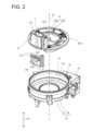
- FIG. 2 is an exploded perspective view in which the rotator is removed from the stator and the holding member is removed from the connector.
- FIG. 3 is a side view of the holding member for illustrating the connection of the flat cable.
- FIG. 4 is a perspective view of the rotator showing the attachment of the holding member.
- FIG. 5 is an enlarged view of the cable assembly according to the first embodiment.
- FIG. 6 is a cross-sectional view of the cable assembly taken along line VI-VI in FIG.
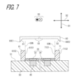
- FIG. 7 is a diagram showing a method of forming the first connecting portion and the second connecting portion according to the first embodiment.
- FIG. 8 is a flowchart showing a method for forming the first connecting portion and the second connecting portion according to the first embodiment.
- FIG. 9 is a diagram showing a first modified example of the method of forming the first connecting portion and the second connecting portion according to the first embodiment.
- FIG. 10 is a diagram showing a second modified example of the method of forming the first connecting portion and the second connecting portion according to the first embodiment.
- FIG. 11 is a diagram showing a third modified example of the method of forming the first connecting portion and the second connecting portion according to the first embodiment.
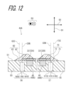
- FIG. 12 is a cross-sectional view of the cable assembly taken along line VI-VI in FIG. 5 when the first connecting portion and the second connecting portion are formed in the third modified example.
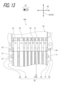
- FIG. 13 is a diagram showing a fourth modified example of the method of forming the first connecting portion and the second connecting portion according to the first embodiment.
- FIG. 14 is an enlarged view of a cable assembly according to a fourth modified example.
- FIG. 15 is an enlarged view of the cable assembly according to the second embodiment.
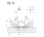
- 16 is a cross-sectional view of the cable assembly taken along line XVI-XVI in FIG. 15.
- FIG. 17 is a diagram showing a method of forming the first connecting portion and the second connecting portion according to the second embodiment.
- FIG. 18 is a flowchart showing a method for forming the first connecting portion and the second connecting portion according to the second embodiment.
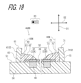
- FIG. 19 is a cross-sectional view of the cable assembly taken along line XVI-XVI in FIG.
- FIG. 20 is an enlarged view of the cable assembly according to the third embodiment.
- FIG. 21 is a cross-sectional view of the cable assembly taken along line XXI-XXI in FIG.
- FIG. 22 is a diagram showing a method of forming the first connecting portion and the second connecting portion according to the third embodiment.
- FIG. 23 is a flowchart showing a method for forming the first connecting portion and the second connecting portion according to the third embodiment.
- FIG. 24 is a cross-sectional view of the cable assembly taken along line XXI-XXI in FIG. 21 when formed using a second modified example of the first connecting portion and the second connecting portion according to the third embodiment.
- Fig. 1 is a perspective view of a rotary connector device 100 according to an embodiment.
- Fig. 2 is an exploded perspective view of a stator 10 with a rotator 20 removed and a connector assembly 40 with a holding member 48 removed.
- the rotary connector device 100 includes a stator 10 and a rotator 20.
- the rotator 20 is rotatable around a rotation axis AX relative to the stator 10.
- the stator 10 is configured to be attached to a vehicle body.
- the rotator 20 is configured to be connected to a steering wheel.
- an accommodation space AS is defined between the stator 10 and the rotator 20.
- the rotary connector device 100 includes a flat cable 30, which is an electric cable.
- the flat cable 30 is flexible.
- the flat cable 30 is disposed in the accommodation space AS.
- the flat cable 30 forms a transmission path between the stator 10 and the rotator 20.
- the flat cable 30 includes at least two core wires 32 and a coating material 34.
- the at least two core wires 32 are electrically conductive.
- the coating material 34 is electrically insulating and partially covers the at least two core wires 32. As shown in FIG. 3, the coating material 34 of the flat cable 30 has a cutout 33 near the tip (cable end 31) of the flat cable 30 in the longitudinal direction, which exposes the exposed portions 32E of the at least two core wires 32.
- the stator 10 includes a first stator portion 12 and a second stator portion 14.
- the second stator portion 14 is disposed on the first stator portion 12 and is coupled to the first stator portion 12.
- the first stator portion 12 constitutes a bottom portion 10b of the stator 10.
- the second stator portion 14 constitutes a side wall 101 of the stator 10.
- the first stator portion 12 has a ring shape when the rotary connector device 100 is viewed in an axial direction AD that is substantially parallel to the rotation axis AX.
- the first stator portion 12 is disposed so that the rotation axis AX passes through the center of the first stator portion 12.
- the second stator portion 14 has a cylindrical shape with a hollow portion 14a of the second stator portion 14 extending in the axial direction AD.
- the second stator portion 14 extends upward from the outer periphery 12a of the first stator portion 12 in the axial direction AD.
- the rotator 20 includes an annular member 200 and an inner cylindrical portion 210.
- the annular member 200 has a ring shape when the rotary connector device 100 is viewed in the axial direction AD.
- the annular member 200 has an opening 202 (see FIG. 4) through which the flat cable 30 passes.
- the annular member 200 is disposed so that the rotation axis AX passes through the center of the annular member 200.
- the inner cylindrical portion 210 is disposed so that the hollow portion 210a of the inner cylindrical portion 210 extends in the axial direction AD.
- the inner cylindrical portion 210 extends downward from the inner circumference 200a of the annular member 200 along the axial direction AD.
- the inner cylindrical portion 210 is disposed inside the cylindrical second stator portion 14 in the radial direction of the rotation axis AX.
- the accommodating space AS in which the flat cable 30 is disposed is defined by the first stator portion 12, the second stator portion 14, the annular member 200, and the inner cylindrical portion 210.
- the accommodating space AS in which the flat cable 30 is disposed is equal to the space obtained by excluding the hollow portion 210a of the inner cylindrical portion 210 from the hollow portion 14a of the second stator portion 14.
- the inner cylindrical portion 210 is provided in the rotator 20.
- the inner cylindrical portion 210 may be provided in the stator 10.
- the rotary connector device 100 has a shape having a hollow portion 210a, but the rotary connector device 100 does not have to have the hollow portion 210a. ⁇ Connector configuration> As shown in FIG. 1, the rotary connector device 100 includes a connector assembly 40 on the rotator 20 side and a connector assembly 49 on the stator 10 side.
- the connector assembly 40 is connected to the rotator 20.
- the connector assembly 40 has a cover 42 and cable assemblies 44A and 44B.
- the cover 42 extends upward from the annular member 200 in the axial direction AD.
- the cover 42 has a space S inside.
- the space S is open at the top in the axial direction AD.
- the opening 202 (see FIG. 4) of the annular member 200 opens the space S at the bottom in the axial direction AD.
- the cable assemblies 44A and 44B are arranged in the space S in an assembled state as shown in FIG. 2. That is, a part of the cable assemblies 44A and 44B is covered by the cover 42.
- the cable assemblies 44A and 44B are electrically connected to at least two core wires 32 of the flat cable 30 via at least two bus bars 46.
- the at least two bus bars 46 and the at least two core wires 32 are electrically connected by, for example, resistance welding or ultrasonic welding.
- the connector assembly 49 on the stator 10 side is connected to the stator 10.
- the connector assembly 49 is disposed outside the stator 10 in the radial direction of the rotation axis AX, but the connector assembly 49 may be disposed below the stator 10 in the axial direction AD.
- the connector assembly 49 has a bus bar electrically connected to at least two core wires 32 of the flat cable 30.
- Fig. 3 is a side view of the holding member 48 for explaining the connection of the flat cable 30. However, Fig. 3 illustrates the side of the holding member 48 in a state in which the connector body 50 is removed from the connector base 41.
- the cable assembly 44A includes the connector 45.
- the connector 45 is described as a connector connected to the rotator 20, but the connector connected to the connector assembly 49 on the stator 10 side may also have the same structure.
- the connector 45 includes at least two bus bars 46 for electrical connection with at least two core wires 32 of the flat cable 30.
- the at least two bus bars 46 are conductive.
- the connector 45 includes a holding member 48 for holding at least two bus bars 46.
- the holding member 48 includes a connector base 41 and a connector body 50.
- the connector base 41 and the connector body 50 are detachable.
- the connector body 50 is electrically insulating and partially covers at least two bus bars 46.
- At least two bus bars 46 extend from the connector body 50 in the axial direction AD.
- At least two bus bars 46 are exposed from the connector body 50 in a direction substantially perpendicular to the axial direction AD.
- the direction substantially perpendicular to the axial direction AD may be referred to as the first direction D1
- the axial direction AD may be referred to as the third direction D3.
- the direction perpendicular to both the first direction D1 and the third direction D3 and in which at least two bus bars 46 are arranged is referred to as the second direction D2.
- the connector body 50 includes a mounting surface 51 on which the flat cable 30 is placed, a body wall portion 52 extending in the second direction D2 against which the cable end 31 of the flat cable 30 can abut, a first protrusion 53 protruding in the second direction D2 and capable of abutting against the covering material 34 of the flat cable 30, and a second protrusion 54 protruding in the second direction D2 and capable of abutting against the covering material 34 of the flat cable 30.
- the first direction D1 is substantially perpendicular to the mounting surface 51.
- the connector body 50 is attached to the connector base 41 with the at least two core wires 32 of the flat cable 30 connected. With the connector body 50 attached, the connector base 41 is attached to the connector 45 in the space S. As a result, at least two bus bars 46 are arranged in the space S.
- the connector base 41 of the holding member 48 has a mating portion 49E.
- the cover 42 has a mated portion 42E provided in the space S.
- the holding member 48 is attached to the cover 42 in the space S by the mating portion 49E mating with the mated portion 42E along the axial direction AD.
- the attachment of the holding member 48 to the cover 42 is not limited to this structure.
- the connector base 41 has an exposed portion 41E (see FIG. 1) that is exposed outside the space S when the holding member 48 is attached to the cover 42.
- the cable assembly 44A further includes a first connecting portion 60 made of a thermoplastic resin provided on the mounting surface 51.
- the first connecting portion 60 connects the covering material 34 and the connector body 50 so as to suppress movement of the flat cable 30 relative to the connector 45.
- the first connecting portion 60 includes a first portion 62 and a second portion 63.
- the first portion 62 is provided inside the contour CON of the covering material 34 when viewed from the first direction D1.
- the second portion 63 extends from the first portion 62 and is provided outside the contour CON when viewed from the first direction D1.
- the first portion 62 has a first projected area (the area of the first portion 62 shown in FIG. 5) defined inside the contour CON when viewed from the first direction D1.
- the second portion 63 has a second projected area (the area of the second portion 63 shown in FIG. 5) defined outside the contour when viewed from the first direction D1.
- the first projected area is larger than the second projected area.
- the cable assembly 44A further includes a second connecting portion 70 made of a thermoplastic resin.
- the second connecting portion 70 connects the covering material 34 and the connector body 50 in the second direction D2, opposite to the first connecting portion 60, so as to suppress movement of the flat cable 30 relative to the connector 45.
- the second connecting portion 70 includes a third portion 72 and a fourth portion 73.
- the third portion 72 is provided inside the contour CON when viewed from the first direction D1.
- the fourth portion 73 extends from the third portion 72 and is provided outside the contour CON when viewed from the first direction D1.
- the third portion 72 has a third projected area (the area of the third portion 72 shown in FIG. 5) defined inside the contour CON when viewed from the first direction D1.
- the fourth portion 73 has a fourth projected area (the area of the fourth portion 73 shown in FIG. 5) defined outside the contour CON when viewed from the first direction D1.
- the third projected area is larger than the fourth projected area.
- the first connecting portion 60 and the second connecting portion 70 are formed as follows.
- a flat cable 30 is provided, which includes at least two conductive core wires 32 and a coating material 34 that is electrically insulating and partially covers the at least two core wires 32.
- a connector 45 is provided, which includes at least two conductive bus bars 46 and a connector body 50 that is electrically insulating and partially covers the at least two bus bars 46.
- step S31 of FIG. 8 as shown in FIG. 7, a first protrusion 61 made of a thermoplastic material is provided on the mounting surface 51 of the connector body 50.
- step S32 of FIG. 8 as shown in FIG. 7, a second protrusion 71 made of a thermoplastic material is provided on the mounting surface 51 of the connector body 50.
- the first protrusion 61 and the second protrusion 71 are equal to or smaller than the width of the flat cable 30 (width in the second direction D2 in FIG. 5).
- first protrusion 61 and the second protrusion 71 are equal to or smaller than the width of the flat cable 30, warping near the contour CON of the flat cable 30 can be efficiently suppressed when the flat cable 30 is connected to the connector 45.
- the first protrusion 61 and the second protrusion 71 may be molded integrally with the connector body 50. That is, in step S2, a connector body 50 having a first protrusion 61 and a second protrusion 71 may be provided on the mounting surface 51, in which case step S2 is performed simultaneously with steps S31 and S32.
- step S41 of FIG. 8 the flat cable 30 is placed on the mounting surface 51 in contact with the first protrusion 61 as shown in FIG. 7.
- step S42 of FIG. 8 the flat cable 30 is placed on the mounting surface 51 in contact with the second protrusion 71 as shown in FIG. 7.
- the cable end 31 of the flat cable 30 is placed on the body wall 52 as shown in FIG. 5.
- the covering material 34 of the flat cable 30 is placed on the first protrusion 53.
- the covering material 34 of the flat cable 30 is placed on the second protrusion 54.
- the first protrusion 53 protrudes in the second direction D2 toward the exposed portions 32E of at least two core wires 32 in the cutout 33.
- the second protrusion 54 protrudes in the second direction D2 toward the exposed portions 32E of at least two core wires 32 in the cutout 33, opposite the first protrusion 53 in the second direction D2.
- the inner surface of the first protrusion 61 that abuts against the contour CON of the flat cable 30 is referred to as the first protrusion inner surface 61S1
- the surface of the first protrusion 61 opposite the first protrusion inner surface 61S1 in the second direction D2 is referred to as the first protrusion outer surface 61S2.
- the inner surface of the second protrusion 71 that abuts against the contour CON of the flat cable 30 is referred to as the second protrusion inner surface 71S1
- the surface of the second protrusion 71 opposite the second protrusion inner surface 71S1 in the second direction D2 is referred to as the second protrusion outer surface 71S2.
- the heating body 80 is brought into contact with the first protrusion 61 to melt the thermoplastic material of the first protrusion 61. More specifically, the first inclined surface 81 of the heating body 80 is brought into contact with the first protrusion 61 to melt the thermoplastic material of the first protrusion 61. The molten thermoplastic material flows on the covering material 34. As a result, the molten thermoplastic material is provided on the covering material 34. In step S52 of FIG. 8, as shown in FIG. 7, the heating body 80 is brought into contact with the second protrusion 71 to melt the thermoplastic material of the second protrusion 71.
- the second inclined surface 82 of the heating body 80 is brought into contact with the second protrusion 71 to melt the thermoplastic material of the second protrusion 71.
- the molten thermoplastic material flows on the covering material 34.
- the molten thermoplastic material is provided on the covering material 34.
- the heating body 80 may be a hot plate or an ultrasonic horn.
- the first inclined surface 81 of the heating element 80 facing the mounting surface 51 is inclined away from the mounting surface 51 in the first direction D1 as it moves from the first outer end 80E1 facing the first protrusion 61 in the first direction D1 toward the surface center 83 facing the flat cable 30.
- the heating element 80 is placed so that the first outer end 80E1 is located outside the first protrusion outer surface 61S2 in the second direction D2. In other words, the heating element 80 is placed so that the first protrusion outer surface 61S2 is located between the first outer end 80E1 and the first protrusion inner surface 61S1 in the second direction D2.
- the second inclined surface 82 of the heating element 80 facing the mounting surface 51 is inclined away from the mounting surface 51 in the first direction D1 as it moves from the second outer end 80E2 facing the second protrusion 71 in the first direction D1 toward the surface center 83 facing the flat cable 30.
- the heating element 80 is positioned so that the second outer end 80E2 is positioned outside the second protrusion outer surface 71S2 in the second direction D2.
- the heating element 80 is positioned so that the second protrusion outer surface 71S2 is positioned between the second outer end 80E2 and the second protrusion inner surface 71S1 in the second direction D2.
- the heating element 80 is moved in the first direction D1 when it is brought into contact with the first protrusion 61 and the second protrusion 71. As a result, the molten thermoplastic material flows toward the inside of the heating element 80, so that more thermoplastic material flows onto the coating material 34.
- step S6 of FIG. 8 the molten thermoplastic material is solidified to form the first connecting portion 60 and the second connecting portion 70.
- Solidifying includes either leaving the molten thermoplastic material at room temperature to solidify, or cooling and solidifying.
- the flat cable 30 is fixed to the mounting surface 51.
- the first connecting portion 60 and the second connecting portion 70 are unshaped because they are formed by melting the thermoplastic material in this way. Unshaped means that they are not molded using a mold or die, and when the first connecting portion 60 and the second connecting portion 70 are viewed from a first direction, they have a distorted shape that deviates from the typical shape formed by a mold or die.
- step S7 of FIG. 8 the exposed portions 32E of the at least two core wires 32 exposed from the coating material 34 are electrically connected to the at least two bus bars 46.
- the at least two core wires 32 and the at least two bus bars 46 are electrically connected at the connection points 35 by resistance welding, ultrasonic welding, or the like.
- step S7 in Fig. 8 may be performed before steps S51 and S52 in Fig. 8. If possible, they may be performed simultaneously. Even in this case, when at least two bus bars 46 and at least two core wires 32 of the flat cable 30 are welded to each other, even if a force that pulls the flat cable 30 off from the welded portion is suddenly applied, the first connecting portion 60 and the second connecting portion 70 prevent the at least two core wires 32 of the flat cable 30 from being pulled off from the at least two bus bars 46.
- the shapes of the first protrusion 61, the second protrusion 71, and the heating body 80 are not limited to those shown in FIG. 7. As shown in FIG.
- the first protrusion 61 may have a first notch 64 recessed in the second direction D2 on the first protrusion inner surface 61S1.
- the second protrusion 71 may have a second notch 74 recessed in the second direction D2 on the second protrusion inner surface 71S1.
- the method of forming the first connecting portion 60 and the second connecting portion 70 according to this modification includes providing the first protrusion 61 having the first notch 64 on the mounting surface 51 in step S31, and providing the second protrusion 71 having the first notch 64 on the mounting surface 51 in step S32.
- the heating body 80 may have a flat surface 84 without the first inclined surface 81 and the second inclined surface 82.
- the surface 84 being flat means that the normal direction of the surface 84 is the first direction D1.
- the heating element 80 abuts against the first protrusion 61 the first protrusion 61 is tilted toward the flat cable 30 by the first notch 64, so that the molten thermoplastic material flows more onto the covering material 34, which has the same effect as the forming method in Fig. 7.
- the heating element 80 abuts against the second protrusion 71 the second protrusion 71 is tilted toward the flat cable 30 by the second notch 74, so that the molten thermoplastic material flows more onto the covering material 34, which has the same effect as the forming method in Fig. 7.
- the heating element 80 has the first inclined surface 81 and the second inclined surface 82, the molten thermoplastic material flows more onto the covering material 34 than in the forming method in Fig. 7.
- the first protrusion 61 may have a first notch 65 recessed in the second direction D2 on the first protrusion outer surface 61S2.
- the second protrusion 71 may have a second notch 75 recessed in the second direction D2 on the second protrusion outer surface 71S2.
- the first protrusion 61 may have the first notch 65 and the second protrusion 71 may have the second notch 75.
- the method of forming the first connecting portion 60 and the second connecting portion 70 according to this modification includes providing the first protrusion 61 having the first notch 65 on the mounting surface 51 in step S31, and providing the second protrusion 71 having the first notch 65 on the mounting surface 51 in step S32.
- the method includes arranging the flat cable 30 so that at least two core wires 32 are aligned in the second direction D2 in steps S41 and S42.
- the first protrusion 61 when the heating element 80 abuts against the first protrusion 61, the first protrusion 61 is pushed by the first inclined surface 81 and inclined toward the flat cable 30 due to the first notch 65, so that a larger amount of molten thermoplastic material flows onto the covering material 34 than in the forming method of Fig. 7.
- the second protrusion 71 When the heating element 80 abuts against the second protrusion 71, the second protrusion 71 is pushed by the second inclined surface 82 and inclined toward the flat cable 30 due to the second notch 75, so that a larger amount of molten thermoplastic material flows onto the covering material 34 than in the forming method of Fig. 7.
- the first protrusion 61 may further have the first notch 64 shown in Fig.
- the second protrusion 71 may further have the second notch 74 shown in Fig. 9.
- the connector body 50 may have the first recess 56 and the second recess 57 on the surface 55 opposite the mounting surface 51 in the first direction D1.
- the connector body 50 may have the first recess 56 and the second recess 57 in a state in which the first protrusion 61 has at least one of the above-described first notches 64, 65 and the second protrusion 71 has at least one of the above-described second notches 74, 75.
- the method for forming the first coupling portion 60 and the second coupling portion 70 according to this modified example includes providing the connector body 50 having the first recess 56 and the second recess 57 on the surface 55 opposite the mounting surface 51 in step S2.
- the center 56C of the first recess 56 in the second direction D2 in which at least two core wires 32 are aligned when the flat cable 30 is fixed to the mounting surface 51 is located between the first core wire 32A that is closest to the first protrusion 61 among the at least two core wires 32 in the second direction D2 and the center 61C of the first protrusion 61 in the second direction D2.
- the inner end 56IE of the first recess 56 in the second direction D2 is located between the first bus bar 46A (or the first core wire 32A) that is closest to the first protrusion 61 among the at least two bus bars 46 in the second direction D2 and the center 61C of the first protrusion 61 in the second direction D2.
- the inner end 56IE of the first recess 56 is located between the first bus bar 46A (or the first core wire 32A) and the first protrusion inner surface 61S1 in the second direction D2.
- the outer end 56EE of the first recess 56 in the second direction D2 is located between the first protrusion outer surface 61S2 and the first protrusion inner surface 61S1 in the second direction D2. More preferably, the outer end 56EE of the first recess 56 is located between the center 61C of the first protrusion 61 in the second direction D2 and the first protrusion inner surface 61S1 in the second direction D2.
- the center 57C of the second recess 57 in the second direction D2 is located between the second core wire 32B that is closest to the second protrusion 71 in the second direction D2 among the at least two core wires 32 and the center 71C of the second protrusion 71 in the second direction D2.
- the inner end 57IE of the second recess 57 in the second direction D2 is located between the second bus bar 46B (or the second core wire 32B) that is closest to the second protrusion 71 in the second direction D2 among the at least two bus bars 46 and the center 71C of the second protrusion 71 in the second direction D2.
- the inner end 57IE of the second recess 57 is located between the second bus bar 46B (or the second core wire 32B) and the second protrusion inner surface 71S1 in the second direction D2.
- the outer end 57EE of the second recess 57 in the second direction D2 is located between the second protrusion outer surface 71S2 and the second protrusion inner surface 71S1 in the second direction D2. More preferably, the outer end 57EE of the second recess 57 is located between the center 71C of the second protrusion 71 in the second direction D2 and the second protrusion inner surface 71S1 in the second direction D2.
- the method of forming the first connecting portion 60 and the second connecting portion 70 according to this modified example includes providing the first protrusion 61 in step S31 such that the center 56C of the first recess 56 in the second direction D2 is located between the first core wire 32A and the center 61C of the first protrusion 61 in the second direction D2 in the second direction D2.
- the thermoplastic material bends so that the center 56C of the first recess 56 is at the lowest position, and the first protrusion 61 tilts toward the flat cable 30, causing a large amount of the molten thermoplastic material to flow onto the coating material 34.
- the forming method includes, in step S31, providing the first protrusion 61 such that the inner end 56IE of the first recess 56 in the second direction D2 is located between the first bus bar 46A (or the first core wire 32A) and the center 61C of the first protrusion 61 in the second direction D2, and the outer end 56EE of the first recess 56 in the second direction D2 is located between the first protrusion outer surface 61S2 and the first protrusion inner surface 61S1 in the second direction D2.
- the inner end 56IE located outside the first bus bar 46A, not only can the thickness of the portion of the connector body 50 made thin by the first recess 56 be reduced, but the first bus bar 46A, which is harder than the connector body 50, does not inhibit deformation.
- the outer end 56EE is located between the first projection outer surface 61S2 and the first projection inner surface 61S1, the portion of the connector body 50 that has been thinned by the first recess 56 is surely heated and deformed when the first projection 61 is heated.
- the forming method includes providing the first protrusion 61 in step S31 such that the inner end 56IE of the first recess 56 is located between the first bus bar 46A (or the first core wire 32A) and the first protrusion inner surface 61S1 in the second direction D2, and the outer end 56EE of the first recess 56 is located between the center 61C of the first protrusion 61 in the second direction D2 and the first protrusion inner surface 61S1 in the second direction D2.
- This causes the first protrusion 61 to be inclined more toward the flat cable 30 when heated, so that more of the molten thermoplastic material flows onto the coating material 34.
- the method of forming the first connecting portion 60 and the second connecting portion 70 according to this modified example includes providing the second protrusion 71 in step S32 so that the center 57C of the second recess 57 in the second direction D2 is located between the second core wire 32B and the center 71C of the second protrusion 71 in the second direction D2 in the second direction D2.
- the second protrusion 71 is heated, when the thermoplastic material bends so that the center 57C of the second recess 57 is at the lowest position, the second protrusion 71 tilts toward the flat cable 30, causing a large amount of the molten thermoplastic material to flow onto the coating material 34.
- the forming method includes, in step S32, providing the second protrusion 71 such that the inner end 57IE of the second recess 57 in the second direction D2 is located between the second bus bar 46B (or the second core wire 32B) and the center 71C of the second protrusion 71 in the second direction D2, and the outer end 57EE of the second recess 57 in the second direction D2 is located between the second protrusion outer surface 71S2 and the second protrusion inner surface 71S1 in the second direction D2.
- the inner end 57IE located outside the second bus bar 46B, not only can the thickness of the portion of the connector body 50 made thin by the second recess 57 be reduced, but the second bus bar 46B, which is harder than the connector body 50, does not inhibit deformation.
- the outer end 57EE is located between the second projection outer surface 71S2 and the second projection inner surface 71S1, the portion of the connector body 50 that has been thinned by the second recess 57 is surely heated and deformed when the second projection 71 is heated.
- the forming method includes providing the second protrusion 71 in step S32 such that the inner end 57IE of the second recess 57 is located between the second bus bar 46B (or the second core wire 32B) and the second protrusion inner surface 71S1 in the second direction D2, and the outer end 57EE of the second recess 57 is located between the center 71C of the second protrusion 71 in the second direction D2 and the second protrusion inner surface 71S1 in the second direction D2.
- This causes the second protrusion 71 to be inclined more toward the flat cable 30 when heated, resulting in more of the molten thermoplastic material flowing onto the coating material 34.
- the shape of the heating element 80 may have a first inclined surface 81 and a second inclined surface 82 as shown in Figs. 7 and 10, or may have a flat surface 84 without the first inclined surface 81 and the second inclined surface 82 as shown in Fig. 9.
- the member (thermoplastic resin) of the connector body 50 that has been thinned by the first recess 56 bends and the first protrusion 61 tilts toward the flat cable 30, causing more of the molten thermoplastic material to flow onto the covering material 34.
- the center 56C of the first recess 56 in the second direction D2, in which at least two bus bars 46 are aligned perpendicular to the first direction D1, is located between the first core wire 32A that is closest to the second portion 63 among the at least two core wires 32 in the second direction D2 and the center 63C of the second portion 63 in the second direction D2.
- the inner end 56IE of the first recess 56 in the second direction D2 is located between the first bus bar 46A (or the first core wire 32A) that is closest to the second portion 63 among the at least two bus bars 46 in the second direction D2 and the center 63C of the second portion 63 in the second direction D2. More preferably, the inner end 56IE of the first recess 56 is located between the first bus bar 46A (or the first core wire 32A) and the contour CON of the coating material 34 in the second direction D2.
- the outer end 56EE of the first recess 56 in the second direction D2 overlaps with the second portion 63 as seen in the first direction D1. More preferably, the outer end 56EE of the first recess 56 is located between the contour CON of the coating material 34 and the center 63C of the second portion 63 in the second direction D2.
- the center 57C of the second recess 57 in the second direction D2 is located between the second core wire 32B, which is the closest to the fourth portion 73 in the second direction D2, of the at least two core wires 32, and the center 73C of the fourth portion 73 in the second direction D2.
- the inner end 57IE of the second recess 57 in the second direction D2 is located between the second bus bar 46B (or the second core wire 32B), which is the closest to the fourth portion 73 in the second direction D2, of the at least two bus bars 46, and the center 73C of the fourth portion 73 in the second direction D2.
- the inner end 57IE of the second recess 57 is located between the second bus bar 46B (or the second core wire 32B) and the contour CON of the coating material 34 in the second direction D2.
- the outer end 57EE of the second recess 57 in the second direction D2 overlaps with the fourth portion 73 when viewed in the first direction D1. More preferably, the outer end 57EE of the second recess 57 is located between the contour CON of the covering material 34 and the center 73C of the fourth portion 73 in the second direction D2.
- the covering material 34 of the flat cable 30 may have a first cover notch 38 recessed in the second direction D2 from a first end 36 of the covering material 34 in the second direction D2 on the side opposite the cable end 31 relative to the cutout 33, without exposing at least two core wires 32.
- the covering material 34 of the flat cable 30 may have a second cover notch 39 recessed in the second direction D2 from a second end 37 of the covering material 34 opposite the first end 36 in the second direction D2, without exposing at least two core wires 32 on the side opposite the cable end 31 relative to the cutout 33.
- the method of forming the first connecting portion 60 and the second connecting portion 70 according to this modification includes providing a flat cable 30 including a covering material 34 having the first cover notch 38 and the second cover notch 39 in step S1.
- the first protrusion 61 is provided on the mounting surface 51 so as to engage with the first cover notch 38
- the second protrusion 71 is provided on the mounting surface 51 so as to engage with the second cover notch 39.
- FIG. 14 an example in which the first connecting portion 60 and the second connecting portion 70 are produced by the method of forming the first connecting portion 60 and the second connecting portion 70 in FIG. 7 or the method of forming the first connecting portion 60 and the second connecting portion 70 in FIG. 7 shown in at least one of the features of the first to fourth modified examples is shown in FIG. 14.
- the second portion 63 of the first connecting portion 60 is provided to engage with the first cover notch 38.
- the fourth portion 43 of the second connecting portion 70 is provided to engage with the second cover notch 39. Note that even in such a case, it is desirable that the first projected area described above is larger than the second projected area described above, and the third projected area described above is larger than the fourth projected area described above.
- the cable assembly 44AB according to the second embodiment further includes a first protrusion 61 adjacent to the first connecting portion 60 and extending from the mounting surface 51 in the first direction D1.
- the second portion 63 of the first connecting portion 60 is provided between the first portion 62 of the first connecting portion 60 and the first protrusion 61 in the second direction D2.
- the first connecting portion 60 and the first protrusion 61 are made of the same material having thermoplasticity and are directly connected.
- the cable assembly 44AB further includes a second protrusion 71 adjacent to the second connecting portion 70 in the second direction D2 and extending from the mounting surface 51 in the first direction D1.
- the fourth portion 73 of the second connecting portion 70 is provided between the third portion 72 of the second connecting portion 70 and the second protrusion 71 in the second direction D2.
- the second connecting portion 70 and the second protrusion 71 are made of the same material having thermoplasticity and are directly connected.
- the first connecting portion 60 and the second connecting portion 70 have the same features as those shown in the first embodiment.
- the heating element 80 is arranged so that the first outer end 80E1 of the heating element 80 is located between the first protrusion outer surface 61S2 and the first protrusion inner surface 61S1 of the first protrusion 61 in the second direction D2.
- the heating element 80 is arranged so that the second outer end 80E2 is located outside the second protrusion outer surface 71S2 in the second direction D2.
- the heating element 80 is arranged so that the second outer end 80E2 of the heating element 80 is located between the second protrusion outer surface 71S2 and the second protrusion inner surface 71S1 of the second protrusion 71 in the second direction D2.
- steps S41 and S42 in FIG. 18 the heating body 80 is moved in the first direction D1. Therefore, in step S51A in FIG. 18, the heating body 80 is brought into contact with a part of the first protrusion 61 to melt the thermoplastic material of the first protrusion 61. The melted thermoplastic material flows on the covering material 34.
- step S52A in FIG. 8 the heating body 80 is brought into contact with a part of the second protrusion 71 to melt the thermoplastic material of the second protrusion 71.
- the melted thermoplastic material flows on the covering material 34.
- the melted thermoplastic material is provided on the covering material 34.
- the length L7 of the heating body 80 in the third direction D3 is longer than the length L8 of the first protrusion 61 in the third direction D3
- the length L7 of the heating body 80 in the third direction D3 is longer than the length L9 of the second protrusion 71 in the third direction D3.
- the method of forming the first connecting portion 60 and the first protrusion 61 and the method of forming the second connecting portion 70 and the second protrusion 71 according to the second embodiment may be any of the first to fourth modified examples shown in the first embodiment.
- the first connecting portion 60 and the first protrusion 61 and the second connecting portion 70 and the second protrusion 71 are formed according to the second modified example, the first protrusion 61 and the second protrusion 71 may be inclined toward the flat cable 30 as shown in FIG.
- the first protrusion 61 is formed so as to surround the first connecting portion 60 from three sides
- the second protrusion 71 is formed so as to surround the second connecting portion 70 from three sides.
- the first protrusion 61 includes a first wall portion 66, a second wall portion 67, and a third wall portion 68.
- the second protrusion 71 includes a fourth wall portion 76, a fifth wall portion 77, and a sixth wall portion 78.
- the first connecting portion 60 and the second connecting portion 70 have the same features as those shown in the first embodiment.
- the first wall portion 66 and the second wall portion 67 can abut against the covering material 34. Referring to FIG. 20, the first wall portion 66 and the second wall portion 67 abut against the covering material 34.
- the second wall portion 67 is provided opposite the first wall portion 66 with respect to the first connecting portion 60 in the third direction D3.
- the third wall portion 68 connects the first wall portion 66 and the second wall portion 67.
- the second portion 63 of the first connecting portion 60 is sandwiched between the third wall portion 68 and the first portion 62 of the first connecting portion 60 in the second direction D2.
- the fourth wall portion 76 and the fifth wall portion 77 can abut against the covering material 34. Referring to FIG. 20, the fourth wall portion 76 and the fifth wall portion 77 abut against the covering material 34.
- the fifth wall portion 77 is provided opposite the fourth wall portion 76 with respect to the second connecting portion 70 in the third direction D3.
- the sixth wall portion 78 connects the fourth wall portion 76 and the fifth wall portion 77.
- the fourth portion 73 of the second connecting portion 70 is sandwiched between the sixth wall portion 78 and the third portion 72 of the second connecting portion 70 in the second direction D2.
- the heating element 80 is arranged such that the first region R1 of the first protrusion 61 that overlaps with the heating element 80 is surrounded by the second region R2 of the first protrusion 61 that does not overlap with the heating element 80 and the region occupied by the flat cable 30 (region R0 defined by the contour CON of the covering material 34).
- the heating element 80 is positioned such that the third region R3 of the second protrusion 71 that overlaps with the heating element 80 is surrounded by the fourth region R4 of the second protrusion 71 that does not overlap with the heating element 80 and the region occupied by the flat cable 30 (region R0 defined by the contour CON of the covering material 34).
- step S41 and S42 the heating element 80 is moved in the first direction D1. Therefore, in step S51B of FIG. 23, the heating element 80 is brought into contact with the first region R1 of the first protrusion 61 to melt the thermoplastic material of the first protrusion 61. The molten thermoplastic material flows over the covering material 34. As a result, the molten thermoplastic material is provided on the covering material 34. In step S52B of FIG. 23, the heating element 80 is brought into contact with the third region R3 of the second protrusion 71 to melt the thermoplastic material of the second protrusion 71. The molten thermoplastic material flows over the covering material 34. As a result, the molten thermoplastic material is provided on the covering material 34.
- the method of forming the first connecting portion 60 and the first protrusion 61 and the method of forming the second connecting portion 70 and the second protrusion 71 according to the third embodiment may be any of the first to fourth modified examples shown in the first embodiment. Note that when the first connecting portion 60 and the first protrusion 61 are formed and the second connecting portion 70 and the second protrusion 71 are formed according to the second modified example, the first protrusion 61 and the second protrusion 71 may be inclined toward the flat cable 30 as shown in FIG. 24.
- the cable assemblies 44A, 44AB, 44AC include a connector 45, a flat cable 30, and a first connecting portion 60.
- the connector 45 includes at least two bus bars 46 that are conductive, and a connector body 50 that is electrically insulating and partially covers the at least two bus bars 46.
- the flat cable 30 includes at least two core wires 32 that are conductive and electrically connected to the at least two bus bars 46, respectively, and a coating material 34 that is electrically insulating and partially covers the at least two core wires 32.
- the first connecting portion 60 connects the coating material 34 and the connector body 50 so as to suppress movement of the flat cable 30 relative to the connector 45.
- the first connecting portion 60 is made of a thermoplastic resin.
- the connector body 50 includes a mounting surface 51 on which the flat cable 30 is placed.
- the first connecting portion 60 includes a first portion 62 that is provided inside the contour CON of the covering material 34 when viewed from a first direction D1 that is substantially perpendicular to the placement surface 51, and a second portion 63 that extends from the first portion 62 and is provided outside the contour CON when viewed from the first direction D1.
- the first portion 62 has a first projected area that is defined inside the contour CON when viewed from the first direction D1.
- the second portion 63 has a second projected area that is defined outside the contour CON when viewed from the first direction D1.
- the first projected area is larger than the second projected area.
- Cable assemblies 44A, 44AB, and 44AC prevent warping of the widthwise ends of flat cable 30 and allow flat cable 30 to be easily and precisely fixed to connector 45. Furthermore, because the first projected area is larger than the second projected area, flat cable 30 can be more strongly fixed to connector 45 by first connecting portion 60.
- a method for manufacturing the cable assemblies 44A, 44AB, and 44AC includes providing a flat cable 30 including at least two conductive core wires 32 and a coating material 34 that is electrically insulating and partially covers the at least two core wires 32.
- the method includes providing a connector 45 including at least two conductive bus bars 46 and a connector body 50 that is electrically insulating and partially covers the at least two bus bars 46.
- the method includes providing a first protrusion 61 made of a thermoplastic material on a mounting surface 51 of the connector body 50.
- the method includes placing the flat cable 30 on the mounting surface 51 in contact with the first protrusion 61.
- the method includes bringing a heater 80 into contact with the first protrusion 61 to melt the thermoplastic material of the first protrusion 61, and providing the molten thermoplastic material on the coating material 34.
- the method includes solidifying the molten thermoplastic material to fix the flat cable 30 to the mounting surface 51.
- the manufacturing method includes electrically connecting the exposed portions 32E of at least two core wires 32 exposed from the coating material 34 to at least two bus bars 46, respectively.
- the method of forming the first connecting portion 60 and the first protrusion 61 and the method of forming the second connecting portion 70 and the second protrusion 71 are not limited to the coupling of the connector 45 and the flat cable 30, but can be applied to a manufacturing method of a cable assembly for fixing the flat cable 30 to a general base having a mounting surface 51.
- the manufacturing method of the cable assembly may provide a base having a mounting surface 51 instead of providing the connector 45.
- step S7 may be omitted in the manufacturing method of the cable assembly.
- the method for manufacturing the cable assembly includes providing a flat cable 30 including at least two conductive core wires 32 and a covering material 34 that is electrically insulating and partially covers the at least two core wires 32.
- the method includes providing a base having a mounting surface 51.
- the method includes providing a first protrusion 61 made of a thermoplastic material on the mounting surface 51.
- the method includes arranging the flat cable 30 on the mounting surface 51 so as to abut against the first protrusion 61.
- the method includes moving a heating element 80 that melts the first protrusion 61 in a first direction D1 substantially perpendicular to the mounting surface 51 while abutting against the first protrusion 61 to melt the thermoplastic material of the first protrusion 61, and providing the molten thermoplastic material on the covering material 34.
- the method includes solidifying the molten thermoplastic material to fix the flat cable 30 to the mounting surface 51.
- the heating element 80 is contacted with the first protrusion 61 such that a first region R1 of the first protrusion 61 that overlaps with the heating element 80 is surrounded by a second region R2 of the first protrusion 61 that does not overlap with the heating element 80 and a region R0 occupied by the flat cable 30.
- ordinal numbers such as “first” and “second” are simply terms for identifying configurations and have no other meaning (such as a particular order). For example, the presence of a “first element” does not imply the presence of a “second element,” and the presence of a “second element” does not imply the presence of a "first element.”
- the expression "at least one of A and B” in this disclosure includes, for example, any of (1) A only, (2) B only, and (3) both A and B.
- the expression "at least one of A, B, and C” includes, for example, any of (1) A only, (2) B only, (3) C only, (4) A and B, (5) B and C, (6) A and C, and (7) all of A, B, and C.
- the expression "at least one of A and B" is not to be interpreted as "at least one of A and at least one of B.”
Landscapes
- Engineering & Computer Science (AREA)
- Manufacturing & Machinery (AREA)
- Chemical & Material Sciences (AREA)
- Combustion & Propulsion (AREA)
- Transportation (AREA)
- Mechanical Engineering (AREA)
- Multi-Conductor Connections (AREA)
- Coupling Device And Connection With Printed Circuit (AREA)
Priority Applications (5)
| Application Number | Priority Date | Filing Date | Title |
|---|---|---|---|
| CN202480015137.6A CN120826849A (zh) | 2023-03-28 | 2024-03-25 | 线缆组装体、旋转连接器装置以及线缆组装体的制造方法 |
| KR1020257036073A KR20250167048A (ko) | 2023-03-28 | 2024-03-25 | 케이블 조립체, 회전 커넥터 장치 및 케이블 조립체의 제조 방법 |
| EP24780203.6A EP4693780A1 (en) | 2023-03-28 | 2024-03-25 | Cable assembly, rotary connector device, and method for manufacturing cable assembly |
| JP2025510870A JPWO2024204086A1 (https=) | 2023-03-28 | 2024-03-25 | |
| US19/340,872 US20260024952A1 (en) | 2023-03-28 | 2025-09-26 | Cable assembly, rotary connector device, and cable assembly manufacturing method |
Applications Claiming Priority (2)
| Application Number | Priority Date | Filing Date | Title |
|---|---|---|---|
| JP2023-051782 | 2023-03-28 | ||
| JP2023051782 | 2023-03-28 |
Related Child Applications (1)
| Application Number | Title | Priority Date | Filing Date |
|---|---|---|---|
| US19/340,872 Continuation US20260024952A1 (en) | 2023-03-28 | 2025-09-26 | Cable assembly, rotary connector device, and cable assembly manufacturing method |
Publications (1)
| Publication Number | Publication Date |
|---|---|
| WO2024204086A1 true WO2024204086A1 (ja) | 2024-10-03 |
Family
ID=92905360
Family Applications (1)
| Application Number | Title | Priority Date | Filing Date |
|---|---|---|---|
| PCT/JP2024/011742 Ceased WO2024204086A1 (ja) | 2023-03-28 | 2024-03-25 | ケーブル組立体、回転コネクタ装置、及びケーブル組立体の製造方法 |
Country Status (6)
| Country | Link |
|---|---|
| US (1) | US20260024952A1 (https=) |
| EP (1) | EP4693780A1 (https=) |
| JP (1) | JPWO2024204086A1 (https=) |
| KR (1) | KR20250167048A (https=) |
| CN (1) | CN120826849A (https=) |
| WO (1) | WO2024204086A1 (https=) |
Citations (7)
| Publication number | Priority date | Publication date | Assignee | Title |
|---|---|---|---|---|
| JP2002373750A (ja) | 2001-06-14 | 2002-12-26 | Alps Electric Co Ltd | 回転コネクタ |
| JP2003007379A (ja) * | 2001-06-25 | 2003-01-10 | Sumitomo Wiring Syst Ltd | フラット電線の接続構造および接続方法 |
| JP2009010063A (ja) * | 2007-06-27 | 2009-01-15 | Panasonic Corp | 電極接合ユニット、電極接合構造体、及び電極接合方法 |
| JP2015067074A (ja) * | 2013-09-27 | 2015-04-13 | 矢崎総業株式会社 | 防音シート組付け構造 |
| JP2015162496A (ja) * | 2014-02-26 | 2015-09-07 | デクセリアルズ株式会社 | 接続体の製造方法、フレキシブル基板の接続方法、接続体及びフレキシブル基板 |
| JP2020044900A (ja) * | 2018-09-18 | 2020-03-26 | 矢崎総業株式会社 | ワイヤハーネスの固定方法 |
| WO2021210325A1 (ja) * | 2020-04-16 | 2021-10-21 | 株式会社オートネットワーク技術研究所 | 配線部材 |
-
2024
- 2024-03-25 JP JP2025510870A patent/JPWO2024204086A1/ja active Pending
- 2024-03-25 WO PCT/JP2024/011742 patent/WO2024204086A1/ja not_active Ceased
- 2024-03-25 CN CN202480015137.6A patent/CN120826849A/zh active Pending
- 2024-03-25 EP EP24780203.6A patent/EP4693780A1/en active Pending
- 2024-03-25 KR KR1020257036073A patent/KR20250167048A/ko active Pending
-
2025
- 2025-09-26 US US19/340,872 patent/US20260024952A1/en active Pending
Patent Citations (7)
| Publication number | Priority date | Publication date | Assignee | Title |
|---|---|---|---|---|
| JP2002373750A (ja) | 2001-06-14 | 2002-12-26 | Alps Electric Co Ltd | 回転コネクタ |
| JP2003007379A (ja) * | 2001-06-25 | 2003-01-10 | Sumitomo Wiring Syst Ltd | フラット電線の接続構造および接続方法 |
| JP2009010063A (ja) * | 2007-06-27 | 2009-01-15 | Panasonic Corp | 電極接合ユニット、電極接合構造体、及び電極接合方法 |
| JP2015067074A (ja) * | 2013-09-27 | 2015-04-13 | 矢崎総業株式会社 | 防音シート組付け構造 |
| JP2015162496A (ja) * | 2014-02-26 | 2015-09-07 | デクセリアルズ株式会社 | 接続体の製造方法、フレキシブル基板の接続方法、接続体及びフレキシブル基板 |
| JP2020044900A (ja) * | 2018-09-18 | 2020-03-26 | 矢崎総業株式会社 | ワイヤハーネスの固定方法 |
| WO2021210325A1 (ja) * | 2020-04-16 | 2021-10-21 | 株式会社オートネットワーク技術研究所 | 配線部材 |
Non-Patent Citations (1)
| Title |
|---|
| See also references of EP4693780A1 |
Also Published As
| Publication number | Publication date |
|---|---|
| US20260024952A1 (en) | 2026-01-22 |
| JPWO2024204086A1 (https=) | 2024-10-03 |
| CN120826849A (zh) | 2025-10-21 |
| KR20250167048A (ko) | 2025-11-28 |
| EP4693780A1 (en) | 2026-02-11 |
Similar Documents
| Publication | Publication Date | Title |
|---|---|---|
| CN109983660B (zh) | 马达和电动助力转向装置 | |
| US7034419B2 (en) | Lead frame and distributing part using same | |
| JP4487851B2 (ja) | 車両用回転検出装置の製造方法 | |
| US11228217B2 (en) | Bus bar assembly and motor | |
| EP3556532B1 (en) | Molded body | |
| US6334251B1 (en) | Method of manufacturing a connecting structure for covered wires | |
| JP2020166950A (ja) | コネクタ装置 | |
| JP2002357617A (ja) | センサ装置 | |
| WO2019155917A1 (ja) | モータ及び電動パワーステアリング装置 | |
| JP5802156B2 (ja) | 回転コネクタ | |
| WO2024204086A1 (ja) | ケーブル組立体、回転コネクタ装置、及びケーブル組立体の製造方法 | |
| JP5930309B2 (ja) | 回転検出装置およびその製造方法 | |
| US12027947B2 (en) | Motor | |
| KR100216115B1 (ko) | 전자 센서 및 그 제조 금형 | |
| JP7651984B2 (ja) | コイル線モジュール、はんだ一体はんだ接合部品及びコイル線モジュールの製造方法 | |
| JP2000357839A (ja) | レーザ装置 | |
| JP7279762B2 (ja) | ハウジング付きケーブル | |
| EP1168527B1 (en) | Rotary connector and connecting structure of flexible cable and lead block used therein | |
| KR20170129726A (ko) | 케이블 접속 구조 및 그 제조 방법 | |
| JP6984027B2 (ja) | 電動機 | |
| JP7616107B2 (ja) | 複合成形部品 | |
| WO2021177427A1 (ja) | コネクタ装置、及びコネクタ装置の製造方法 | |
| JP3062069B2 (ja) | 電磁センサ | |
| JP7632329B2 (ja) | 複合成形部品 | |
| JP2999408B2 (ja) | 電磁センサ及びその製造金型 |
Legal Events
| Date | Code | Title | Description |
|---|---|---|---|
| 121 | Ep: the epo has been informed by wipo that ep was designated in this application |
Ref document number: 24780203 Country of ref document: EP Kind code of ref document: A1 |
|
| WWE | Wipo information: entry into national phase |
Ref document number: CN2024800151376 Country of ref document: CN Ref document number: 202480015137.6 Country of ref document: CN |
|
| ENP | Entry into the national phase |
Ref document number: 2025510870 Country of ref document: JP Kind code of ref document: A |
|
| WWE | Wipo information: entry into national phase |
Ref document number: 2025510870 Country of ref document: JP |
|
| WWP | Wipo information: published in national office |
Ref document number: 202480015137.6 Country of ref document: CN |
|
| ENP | Entry into the national phase |
Ref document number: 1020257036073 Country of ref document: KR Free format text: ST27 STATUS EVENT CODE: A-0-1-A10-A15-NAP-PA0105 (AS PROVIDED BY THE NATIONAL OFFICE) |
|
| WWE | Wipo information: entry into national phase |
Ref document number: KR1020257036073 Country of ref document: KR Ref document number: 2024780203 Country of ref document: EP |
|
| NENP | Non-entry into the national phase |
Ref country code: DE |
|
| ENP | Entry into the national phase |
Ref document number: 2024780203 Country of ref document: EP Effective date: 20251028 |
|
| ENP | Entry into the national phase |
Ref document number: 2024780203 Country of ref document: EP Effective date: 20251028 |
|
| ENP | Entry into the national phase |
Ref document number: 2024780203 Country of ref document: EP Effective date: 20251028 |
|
| ENP | Entry into the national phase |
Ref document number: 2024780203 Country of ref document: EP Effective date: 20251028 |
|
| ENP | Entry into the national phase |
Ref document number: 2024780203 Country of ref document: EP Effective date: 20251028 |
|
| ENP | Entry into the national phase |
Ref document number: 2024780203 Country of ref document: EP Effective date: 20251028 |
|
| ENP | Entry into the national phase |
Ref document number: 2024780203 Country of ref document: EP Effective date: 20251028 |
|
| ENP | Entry into the national phase |
Ref document number: 2024780203 Country of ref document: EP Effective date: 20251028 |
|
| WWP | Wipo information: published in national office |
Ref document number: 2024780203 Country of ref document: EP |