WO2024202250A1 - 磁粉、磁石、磁粉の製造方法および磁石の製造方法 - Google Patents
磁粉、磁石、磁粉の製造方法および磁石の製造方法 Download PDFInfo
- Publication number
- WO2024202250A1 WO2024202250A1 PCT/JP2023/043162 JP2023043162W WO2024202250A1 WO 2024202250 A1 WO2024202250 A1 WO 2024202250A1 JP 2023043162 W JP2023043162 W JP 2023043162W WO 2024202250 A1 WO2024202250 A1 WO 2024202250A1
- Authority
- WO
- WIPO (PCT)
- Prior art keywords
- atomic
- content
- magnetic material
- grain boundary
- phase
- Prior art date
- Legal status (The legal status is an assumption and is not a legal conclusion. Google has not performed a legal analysis and makes no representation as to the accuracy of the status listed.)
- Ceased
Links
Images


Classifications
-
- H—ELECTRICITY
- H01—ELECTRIC ELEMENTS
- H01F—MAGNETS; INDUCTANCES; TRANSFORMERS; SELECTION OF MATERIALS FOR THEIR MAGNETIC PROPERTIES
- H01F1/00—Magnets or magnetic bodies characterised by the magnetic materials therefor; Selection of materials for their magnetic properties
- H01F1/01—Magnets or magnetic bodies characterised by the magnetic materials therefor; Selection of materials for their magnetic properties of inorganic materials
- H01F1/03—Magnets or magnetic bodies characterised by the magnetic materials therefor; Selection of materials for their magnetic properties of inorganic materials characterised by their coercivity
- H01F1/032—Magnets or magnetic bodies characterised by the magnetic materials therefor; Selection of materials for their magnetic properties of inorganic materials characterised by their coercivity of hard-magnetic materials
- H01F1/04—Magnets or magnetic bodies characterised by the magnetic materials therefor; Selection of materials for their magnetic properties of inorganic materials characterised by their coercivity of hard-magnetic materials metals or alloys
- H01F1/047—Alloys characterised by their composition
- H01F1/053—Alloys characterised by their composition containing rare earth metals
- H01F1/055—Alloys characterised by their composition containing rare earth metals and magnetic transition metals, e.g. SmCo5
- H01F1/059—Alloys characterised by their composition containing rare earth metals and magnetic transition metals, e.g. SmCo5 and Va elements, e.g. Sm2Fe17N2
-
- B—PERFORMING OPERATIONS; TRANSPORTING
- B22—CASTING; POWDER METALLURGY
- B22F—WORKING METALLIC POWDER; MANUFACTURE OF ARTICLES FROM METALLIC POWDER; MAKING METALLIC POWDER; APPARATUS OR DEVICES SPECIALLY ADAPTED FOR METALLIC POWDER
- B22F1/00—Metallic powder; Treatment of metallic powder, e.g. to facilitate working or to improve properties
- B22F1/14—Treatment of metallic powder
- B22F1/142—Thermal or thermo-mechanical treatment
-
- B—PERFORMING OPERATIONS; TRANSPORTING
- B22—CASTING; POWDER METALLURGY
- B22F—WORKING METALLIC POWDER; MANUFACTURE OF ARTICLES FROM METALLIC POWDER; MAKING METALLIC POWDER; APPARATUS OR DEVICES SPECIALLY ADAPTED FOR METALLIC POWDER
- B22F1/00—Metallic powder; Treatment of metallic powder, e.g. to facilitate working or to improve properties
- B22F1/14—Treatment of metallic powder
- B22F1/145—Chemical treatment, e.g. passivation or decarburisation
-
- B—PERFORMING OPERATIONS; TRANSPORTING
- B22—CASTING; POWDER METALLURGY
- B22F—WORKING METALLIC POWDER; MANUFACTURE OF ARTICLES FROM METALLIC POWDER; MAKING METALLIC POWDER; APPARATUS OR DEVICES SPECIALLY ADAPTED FOR METALLIC POWDER
- B22F3/00—Manufacture of workpieces or articles from metallic powder characterised by the manner of compacting or sintering; Apparatus specially adapted therefor ; Presses and furnaces
- B22F3/02—Compacting only
-
- B—PERFORMING OPERATIONS; TRANSPORTING
- B22—CASTING; POWDER METALLURGY
- B22F—WORKING METALLIC POWDER; MANUFACTURE OF ARTICLES FROM METALLIC POWDER; MAKING METALLIC POWDER; APPARATUS OR DEVICES SPECIALLY ADAPTED FOR METALLIC POWDER
- B22F9/00—Making metallic powder or suspensions thereof
- B22F9/002—Making metallic powder or suspensions thereof amorphous or microcrystalline
- B22F9/008—Rapid solidification processing
-
- B—PERFORMING OPERATIONS; TRANSPORTING
- B22—CASTING; POWDER METALLURGY
- B22F—WORKING METALLIC POWDER; MANUFACTURE OF ARTICLES FROM METALLIC POWDER; MAKING METALLIC POWDER; APPARATUS OR DEVICES SPECIALLY ADAPTED FOR METALLIC POWDER
- B22F9/00—Making metallic powder or suspensions thereof
- B22F9/02—Making metallic powder or suspensions thereof using physical processes
- B22F9/04—Making metallic powder or suspensions thereof using physical processes starting from solid material, e.g. by crushing, grinding or milling
-
- C—CHEMISTRY; METALLURGY
- C22—METALLURGY; FERROUS OR NON-FERROUS ALLOYS; TREATMENT OF ALLOYS OR NON-FERROUS METALS
- C22C—ALLOYS
- C22C33/00—Making ferrous alloys
- C22C33/02—Making ferrous alloys by powder metallurgy
- C22C33/0257—Making ferrous alloys by powder metallurgy characterised by the range of the alloying elements
-
- C—CHEMISTRY; METALLURGY
- C22—METALLURGY; FERROUS OR NON-FERROUS ALLOYS; TREATMENT OF ALLOYS OR NON-FERROUS METALS
- C22C—ALLOYS
- C22C38/00—Ferrous alloys, e.g. steel alloys
-
- C—CHEMISTRY; METALLURGY
- C22—METALLURGY; FERROUS OR NON-FERROUS ALLOYS; TREATMENT OF ALLOYS OR NON-FERROUS METALS
- C22C—ALLOYS
- C22C38/00—Ferrous alloys, e.g. steel alloys
- C22C38/001—Ferrous alloys, e.g. steel alloys containing N
-
- C—CHEMISTRY; METALLURGY
- C22—METALLURGY; FERROUS OR NON-FERROUS ALLOYS; TREATMENT OF ALLOYS OR NON-FERROUS METALS
- C22C—ALLOYS
- C22C38/00—Ferrous alloys, e.g. steel alloys
- C22C38/002—Ferrous alloys, e.g. steel alloys containing In, Mg, or other elements not provided for in one single group C22C38/001 - C22C38/60
-
- C—CHEMISTRY; METALLURGY
- C22—METALLURGY; FERROUS OR NON-FERROUS ALLOYS; TREATMENT OF ALLOYS OR NON-FERROUS METALS
- C22C—ALLOYS
- C22C38/00—Ferrous alloys, e.g. steel alloys
- C22C38/005—Ferrous alloys, e.g. steel alloys containing rare earths, i.e. Sc, Y, Lanthanides
-
- C—CHEMISTRY; METALLURGY
- C22—METALLURGY; FERROUS OR NON-FERROUS ALLOYS; TREATMENT OF ALLOYS OR NON-FERROUS METALS
- C22C—ALLOYS
- C22C38/00—Ferrous alloys, e.g. steel alloys
- C22C38/02—Ferrous alloys, e.g. steel alloys containing silicon
-
- C—CHEMISTRY; METALLURGY
- C22—METALLURGY; FERROUS OR NON-FERROUS ALLOYS; TREATMENT OF ALLOYS OR NON-FERROUS METALS
- C22C—ALLOYS
- C22C38/00—Ferrous alloys, e.g. steel alloys
- C22C38/04—Ferrous alloys, e.g. steel alloys containing manganese
-
- C—CHEMISTRY; METALLURGY
- C22—METALLURGY; FERROUS OR NON-FERROUS ALLOYS; TREATMENT OF ALLOYS OR NON-FERROUS METALS
- C22C—ALLOYS
- C22C38/00—Ferrous alloys, e.g. steel alloys
- C22C38/10—Ferrous alloys, e.g. steel alloys containing cobalt
-
- C—CHEMISTRY; METALLURGY
- C22—METALLURGY; FERROUS OR NON-FERROUS ALLOYS; TREATMENT OF ALLOYS OR NON-FERROUS METALS
- C22C—ALLOYS
- C22C38/00—Ferrous alloys, e.g. steel alloys
- C22C38/12—Ferrous alloys, e.g. steel alloys containing tungsten, tantalum, molybdenum, vanadium, or niobium
-
- C—CHEMISTRY; METALLURGY
- C22—METALLURGY; FERROUS OR NON-FERROUS ALLOYS; TREATMENT OF ALLOYS OR NON-FERROUS METALS
- C22C—ALLOYS
- C22C38/00—Ferrous alloys, e.g. steel alloys
- C22C38/14—Ferrous alloys, e.g. steel alloys containing titanium or zirconium
-
- C—CHEMISTRY; METALLURGY
- C22—METALLURGY; FERROUS OR NON-FERROUS ALLOYS; TREATMENT OF ALLOYS OR NON-FERROUS METALS
- C22C—ALLOYS
- C22C38/00—Ferrous alloys, e.g. steel alloys
- C22C38/18—Ferrous alloys, e.g. steel alloys containing chromium
-
- C—CHEMISTRY; METALLURGY
- C23—COATING METALLIC MATERIAL; COATING MATERIAL WITH METALLIC MATERIAL; CHEMICAL SURFACE TREATMENT; DIFFUSION TREATMENT OF METALLIC MATERIAL; COATING BY VACUUM EVAPORATION, BY SPUTTERING, BY ION IMPLANTATION OR BY CHEMICAL VAPOUR DEPOSITION, IN GENERAL; INHIBITING CORROSION OF METALLIC MATERIAL OR INCRUSTATION IN GENERAL
- C23C—COATING METALLIC MATERIAL; COATING MATERIAL WITH METALLIC MATERIAL; SURFACE TREATMENT OF METALLIC MATERIAL BY DIFFUSION INTO THE SURFACE, BY CHEMICAL CONVERSION OR SUBSTITUTION; COATING BY VACUUM EVAPORATION, BY SPUTTERING, BY ION IMPLANTATION OR BY CHEMICAL VAPOUR DEPOSITION, IN GENERAL
- C23C8/00—Solid state diffusion of only non-metal elements into metallic material surfaces; Chemical surface treatment of metallic material by reaction of the surface with a reactive gas, leaving reaction products of surface material in the coating, e.g. conversion coatings, passivation of metals
- C23C8/06—Solid state diffusion of only non-metal elements into metallic material surfaces; Chemical surface treatment of metallic material by reaction of the surface with a reactive gas, leaving reaction products of surface material in the coating, e.g. conversion coatings, passivation of metals using gases
- C23C8/08—Solid state diffusion of only non-metal elements into metallic material surfaces; Chemical surface treatment of metallic material by reaction of the surface with a reactive gas, leaving reaction products of surface material in the coating, e.g. conversion coatings, passivation of metals using gases only one element being applied
- C23C8/24—Nitriding
- C23C8/26—Nitriding of ferrous surfaces
-
- C—CHEMISTRY; METALLURGY
- C23—COATING METALLIC MATERIAL; COATING MATERIAL WITH METALLIC MATERIAL; CHEMICAL SURFACE TREATMENT; DIFFUSION TREATMENT OF METALLIC MATERIAL; COATING BY VACUUM EVAPORATION, BY SPUTTERING, BY ION IMPLANTATION OR BY CHEMICAL VAPOUR DEPOSITION, IN GENERAL; INHIBITING CORROSION OF METALLIC MATERIAL OR INCRUSTATION IN GENERAL
- C23C—COATING METALLIC MATERIAL; COATING MATERIAL WITH METALLIC MATERIAL; SURFACE TREATMENT OF METALLIC MATERIAL BY DIFFUSION INTO THE SURFACE, BY CHEMICAL CONVERSION OR SUBSTITUTION; COATING BY VACUUM EVAPORATION, BY SPUTTERING, BY ION IMPLANTATION OR BY CHEMICAL VAPOUR DEPOSITION, IN GENERAL
- C23C8/00—Solid state diffusion of only non-metal elements into metallic material surfaces; Chemical surface treatment of metallic material by reaction of the surface with a reactive gas, leaving reaction products of surface material in the coating, e.g. conversion coatings, passivation of metals
- C23C8/80—After-treatment
-
- H—ELECTRICITY
- H01—ELECTRIC ELEMENTS
- H01F—MAGNETS; INDUCTANCES; TRANSFORMERS; SELECTION OF MATERIALS FOR THEIR MAGNETIC PROPERTIES
- H01F1/00—Magnets or magnetic bodies characterised by the magnetic materials therefor; Selection of materials for their magnetic properties
- H01F1/01—Magnets or magnetic bodies characterised by the magnetic materials therefor; Selection of materials for their magnetic properties of inorganic materials
- H01F1/03—Magnets or magnetic bodies characterised by the magnetic materials therefor; Selection of materials for their magnetic properties of inorganic materials characterised by their coercivity
- H01F1/032—Magnets or magnetic bodies characterised by the magnetic materials therefor; Selection of materials for their magnetic properties of inorganic materials characterised by their coercivity of hard-magnetic materials
- H01F1/04—Magnets or magnetic bodies characterised by the magnetic materials therefor; Selection of materials for their magnetic properties of inorganic materials characterised by their coercivity of hard-magnetic materials metals or alloys
- H01F1/06—Magnets or magnetic bodies characterised by the magnetic materials therefor; Selection of materials for their magnetic properties of inorganic materials characterised by their coercivity of hard-magnetic materials metals or alloys in the form of particles, e.g. powder
- H01F1/08—Magnets or magnetic bodies characterised by the magnetic materials therefor; Selection of materials for their magnetic properties of inorganic materials characterised by their coercivity of hard-magnetic materials metals or alloys in the form of particles, e.g. powder pressed, sintered, or bound together
-
- H—ELECTRICITY
- H01—ELECTRIC ELEMENTS
- H01F—MAGNETS; INDUCTANCES; TRANSFORMERS; SELECTION OF MATERIALS FOR THEIR MAGNETIC PROPERTIES
- H01F41/00—Apparatus or processes specially adapted for manufacturing or assembling magnets, inductances or transformers; Apparatus or processes specially adapted for manufacturing materials characterised by their magnetic properties
- H01F41/02—Apparatus or processes specially adapted for manufacturing or assembling magnets, inductances or transformers; Apparatus or processes specially adapted for manufacturing materials characterised by their magnetic properties for manufacturing cores, coils, or magnets
-
- H—ELECTRICITY
- H01—ELECTRIC ELEMENTS
- H01F—MAGNETS; INDUCTANCES; TRANSFORMERS; SELECTION OF MATERIALS FOR THEIR MAGNETIC PROPERTIES
- H01F41/00—Apparatus or processes specially adapted for manufacturing or assembling magnets, inductances or transformers; Apparatus or processes specially adapted for manufacturing materials characterised by their magnetic properties
- H01F41/02—Apparatus or processes specially adapted for manufacturing or assembling magnets, inductances or transformers; Apparatus or processes specially adapted for manufacturing materials characterised by their magnetic properties for manufacturing cores, coils, or magnets
- H01F41/0253—Apparatus or processes specially adapted for manufacturing or assembling magnets, inductances or transformers; Apparatus or processes specially adapted for manufacturing materials characterised by their magnetic properties for manufacturing cores, coils, or magnets for manufacturing permanent magnets
- H01F41/0266—Moulding; Pressing
-
- H—ELECTRICITY
- H01—ELECTRIC ELEMENTS
- H01F—MAGNETS; INDUCTANCES; TRANSFORMERS; SELECTION OF MATERIALS FOR THEIR MAGNETIC PROPERTIES
- H01F7/00—Magnets
- H01F7/02—Permanent magnets [PM]
-
- B—PERFORMING OPERATIONS; TRANSPORTING
- B22—CASTING; POWDER METALLURGY
- B22F—WORKING METALLIC POWDER; MANUFACTURE OF ARTICLES FROM METALLIC POWDER; MAKING METALLIC POWDER; APPARATUS OR DEVICES SPECIALLY ADAPTED FOR METALLIC POWDER
- B22F1/00—Metallic powder; Treatment of metallic powder, e.g. to facilitate working or to improve properties
- B22F1/10—Metallic powder containing lubricating or binding agents; Metallic powder containing organic material
-
- B—PERFORMING OPERATIONS; TRANSPORTING
- B22—CASTING; POWDER METALLURGY
- B22F—WORKING METALLIC POWDER; MANUFACTURE OF ARTICLES FROM METALLIC POWDER; MAKING METALLIC POWDER; APPARATUS OR DEVICES SPECIALLY ADAPTED FOR METALLIC POWDER
- B22F9/00—Making metallic powder or suspensions thereof
- B22F9/02—Making metallic powder or suspensions thereof using physical processes
- B22F9/04—Making metallic powder or suspensions thereof using physical processes starting from solid material, e.g. by crushing, grinding or milling
- B22F2009/048—Making metallic powder or suspensions thereof using physical processes starting from solid material, e.g. by crushing, grinding or milling by pulverising a quenched ribbon
-
- B—PERFORMING OPERATIONS; TRANSPORTING
- B22—CASTING; POWDER METALLURGY
- B22F—WORKING METALLIC POWDER; MANUFACTURE OF ARTICLES FROM METALLIC POWDER; MAKING METALLIC POWDER; APPARATUS OR DEVICES SPECIALLY ADAPTED FOR METALLIC POWDER
- B22F2201/00—Treatment under specific atmosphere
- B22F2201/01—Reducing atmosphere
- B22F2201/013—Hydrogen
-
- B—PERFORMING OPERATIONS; TRANSPORTING
- B22—CASTING; POWDER METALLURGY
- B22F—WORKING METALLIC POWDER; MANUFACTURE OF ARTICLES FROM METALLIC POWDER; MAKING METALLIC POWDER; APPARATUS OR DEVICES SPECIALLY ADAPTED FOR METALLIC POWDER
- B22F2201/00—Treatment under specific atmosphere
- B22F2201/01—Reducing atmosphere
- B22F2201/016—NH3
-
- B—PERFORMING OPERATIONS; TRANSPORTING
- B22—CASTING; POWDER METALLURGY
- B22F—WORKING METALLIC POWDER; MANUFACTURE OF ARTICLES FROM METALLIC POWDER; MAKING METALLIC POWDER; APPARATUS OR DEVICES SPECIALLY ADAPTED FOR METALLIC POWDER
- B22F2201/00—Treatment under specific atmosphere
- B22F2201/10—Inert gases
- B22F2201/11—Argon
-
- B—PERFORMING OPERATIONS; TRANSPORTING
- B22—CASTING; POWDER METALLURGY
- B22F—WORKING METALLIC POWDER; MANUFACTURE OF ARTICLES FROM METALLIC POWDER; MAKING METALLIC POWDER; APPARATUS OR DEVICES SPECIALLY ADAPTED FOR METALLIC POWDER
- B22F2301/00—Metallic composition of the powder or its coating
- B22F2301/35—Iron
- B22F2301/355—Rare Earth - Fe intermetallic alloys
-
- B—PERFORMING OPERATIONS; TRANSPORTING
- B22—CASTING; POWDER METALLURGY
- B22F—WORKING METALLIC POWDER; MANUFACTURE OF ARTICLES FROM METALLIC POWDER; MAKING METALLIC POWDER; APPARATUS OR DEVICES SPECIALLY ADAPTED FOR METALLIC POWDER
- B22F2998/00—Supplementary information concerning processes or compositions relating to powder metallurgy
- B22F2998/10—Processes characterised by the sequence of their steps
-
- B—PERFORMING OPERATIONS; TRANSPORTING
- B22—CASTING; POWDER METALLURGY
- B22F—WORKING METALLIC POWDER; MANUFACTURE OF ARTICLES FROM METALLIC POWDER; MAKING METALLIC POWDER; APPARATUS OR DEVICES SPECIALLY ADAPTED FOR METALLIC POWDER
- B22F2999/00—Aspects linked to processes or compositions used in powder metallurgy
-
- B—PERFORMING OPERATIONS; TRANSPORTING
- B22—CASTING; POWDER METALLURGY
- B22F—WORKING METALLIC POWDER; MANUFACTURE OF ARTICLES FROM METALLIC POWDER; MAKING METALLIC POWDER; APPARATUS OR DEVICES SPECIALLY ADAPTED FOR METALLIC POWDER
- B22F3/00—Manufacture of workpieces or articles from metallic powder characterised by the manner of compacting or sintering; Apparatus specially adapted therefor ; Presses and furnaces
- B22F3/22—Manufacture of workpieces or articles from metallic powder characterised by the manner of compacting or sintering; Apparatus specially adapted therefor ; Presses and furnaces for producing castings from a slip
- B22F3/225—Manufacture of workpieces or articles from metallic powder characterised by the manner of compacting or sintering; Apparatus specially adapted therefor ; Presses and furnaces for producing castings from a slip by injection molding
-
- C—CHEMISTRY; METALLURGY
- C22—METALLURGY; FERROUS OR NON-FERROUS ALLOYS; TREATMENT OF ALLOYS OR NON-FERROUS METALS
- C22C—ALLOYS
- C22C2202/00—Physical properties
- C22C2202/02—Magnetic
Definitions
- This disclosure relates to magnetic powder, magnets, methods for manufacturing magnetic powder, and methods for manufacturing magnets.
- Rare earth magnets have a high magnetic flux density and can be made into extremely powerful permanent magnets, and are used in a variety of applications.
- One type of rare earth magnet known is the Sm-Fe-N magnet.
- Sm-Fe-N magnets are typically manufactured by nitriding Sm-Fe polycrystals. When N atoms are dissolved in the crystal lattice of Sm-Fe polycrystals, the lattice becomes distorted and uniaxial magnetic anisotropy is expressed. The resulting Sm-Fe-N magnetic material is thought to be capable of functioning as a hard magnetic material.
- Patent Document 1 describes the production of a flake-shaped isotropic Sm-Fe-N powder magnet material by nitriding a powder of a magnet alloy obtained by a roll quenching method, and describes that the material has a composition, in atomic %, of Sm x Fe 100-x-v N v (wherein 7 ⁇ x ⁇ 12 and 0.5 ⁇ v ⁇ 20), a TbCu type crystal structure, and a flake thickness of 10 to 30 ⁇ m.
- Patent Document 2 describes a rare earth permanent magnet material as an Sm-Fe-N based magnetic material, whose composition, expressed in atomic percent, is represented by Sm x R a Fe 100-x-y-za M y N z (wherein R is at least one of Zr and Hf, M is at least one of Co, Ti, Nb, Cr, V, Mo, Si, Ga, Ni, Mn, and Al, x+a is 7% to 10%, a is 0% to 1.5%, y is 0% to 5%, and z is 10% to 14%).
- R is at least one of Zr and Hf
- M is at least one of Co, Ti, Nb, Cr, V, Mo, Si, Ga, Ni, Mn, and Al
- x+a is 7% to 10%
- a is 0% to 1.5%
- y 0% to 5%
- z is 10% to 14%).
- the Sm-Fe-N magnetic materials described in Patent Documents 1 and 2 are both manufactured without further heat treatment after nitriding. According to the inventors' studies, the Sm-Fe-N magnetic materials described in Patent Documents 1 and 2 do not have sufficient coercive force, and in applications requiring heat resistance in particular, they are demagnetized and are unable to exhibit sufficient characteristics.
- One example of an application requiring heat resistance is an in-vehicle application, which may require heat resistance of 120°C or higher.
- the objective of this disclosure is to provide an Sm-Fe-N magnetic material with good coercive force.
- the objective of this disclosure is to provide a method for manufacturing such an Sm-Fe-N magnetic material.
- the Sm—Fe—N based magnetic material of the present disclosure is a main phase consisting of a plurality of Sm—Fe—N crystal grains; a grain boundary phase that is present between adjacent Sm—Fe—N crystal grains and contains N; The ratio of the N content in the main phase to the N content in the grain boundary phase is 0.84 or more on an atomic basis.
- an Sm-Fe-N magnetic material with good coercive force it is possible to provide an Sm-Fe-N magnetic material with good coercive force.
- 1 shows the results of STEM-EDX analysis of the Sm—Fe—N based magnetic material obtained in Example 1, in which DF-I is a dark-field image and N is a mapping image (element distribution image) showing the concentration distribution of N atoms.
- 1 shows the results of STEM-EDX analysis of the Sm—Fe—N based magnetic material obtained in Comparative Example 1, in which DF-I is a dark-field image and N is a mapping image (element distribution image) showing the concentration distribution of N atoms.
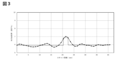
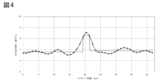
- 2 is a line profile showing the concentration distribution of N atoms in the Sm—Fe—N based magnetic material obtained in Example 1, corresponding to the arrows in FIG. 3 is a line profile showing the concentration distribution of N atoms in the Sm—Fe—N based magnetic material obtained in Comparative Example 1, which corresponds to the arrows in FIG. 2 .
- the Sm—Fe—N based magnetic material of the present disclosure is a main phase consisting of a plurality of Sm—Fe—N crystal grains; a grain boundary phase that is present between adjacent Sm—Fe—N crystal grains and contains N; The ratio of the N content in the main phase to the N content in the grain boundary phase is 0.84 or more on an atomic basis.
- the Sm-Fe-N magnetic material disclosed herein has the above-mentioned structure and therefore has good coercive force. Although it should not be interpreted as being limited to a specific theory, the reason why the Sm-Fe-N magnetic material disclosed herein exhibits the above-mentioned effects is thought to be as follows.
- N atoms dissolve in the crystal lattice of Sm-Fe polycrystals, distorting the lattice and resulting in the expression of uniaxial magnetic anisotropy.
- N atoms are preferentially distributed in the grain boundary phase, with limited distribution in the main phase, so it is believed that the effect of improving magnetic anisotropy does not necessarily reflect the N content.
- the ratio of the N content in the main phase to the N content in the grain boundary phase is increased, so that the effect of improving magnetic anisotropy is exerted and the coercive force of the magnetic material is improved.
- the ratio of the N content in the main phase to the N content in the grain boundary phase is 0.84 or more, preferably 0.85 or more, on an atomic basis, and may be, for example, less than 1, 0.99 or less.
- the N content ratio is within this range, the coercive force of the Sm-Fe-N magnetic material can be improved.
- the content of N in the main phase and the grain boundary phase can be measured by energy dispersive X-ray analysis using a scanning transmission electron microscope (STEM-EDX).
- STEM-EDX scanning transmission electron microscope
- a Sm-Fe-N magnetic material an element distribution diagram is obtained in a field of view including a plurality of main phases and grain boundary phases.
- a location where a phase thought to be a grain boundary formed between crystal grains is oriented parallel to the direction of incidence of the electron beam is selected, and a line profile showing the content of N atoms is extracted with a direction perpendicular to the grain boundary phase as the scanning direction.
- the content of N is measured with the position where the content of N is at its peak as the center, and the region 1 nm before and after the center (total of 2 nm) along the scanning direction is set as the grain boundary phase, and the other region is set as the main phase.
- This measurement is carried out at three or more different points in a visual field (e.g., 522 ⁇ 522 nm 2 ) that contains 50 or more crystal grains of the main phase, and the N contents in the regions corresponding to the main phase or grain boundary phase are number-averaged based on the N contents at each measurement point to obtain the N content in each phase.
- a visual field e.g., 522 ⁇ 522 nm 2
- the N content in the main phase is divided by the N content in the grain boundary phase to calculate the ratio of the N content in the main phase to the N content in the grain boundary phase.
- the sample for STEM-EDX analysis of the Sm—Fe—N magnetic material may be processed, for example, by a focused ion beam device (FIB).
- FIB focused ion beam device
- a line profile may be obtained by scanning an electron beam perpendicular to the grain boundary, or another method may be used as long as the spatial resolution and detection accuracy satisfy the purpose, such as electron energy loss spectroscopy using a transmission electron microscope (TEM-EELS), electron energy loss spectroscopy using a scanning transmission electron microscope (STEM-EELS), or three-dimensional atom probe (3DAP).
- TEM-EELS transmission electron microscope
- STEM-EELS scanning transmission electron microscope
- 3DAP three-dimensional atom probe
- energy dispersive X-ray analysis using a scanning transmission electron microscope is preferred, taking into account spatial resolution, detection sensitivity, quantitative accuracy, the width of the analyzable area, versatility, etc.
- the Sm content is preferably 7.0 atomic % or more and 11.5 atomic % or less, and more preferably 7.0 atomic % or more and 11.2 atomic % or less, out of a total of 100 atomic % of the elements contained in the Sm-Fe-N magnetic material.
- the Fe content is preferably 61.5 atomic % or more and 78.5 atomic % or less, more preferably 61.6 atomic % or more and 78.0 atomic % or less, and even more preferably 61.6 atomic % or more and 74.0 atomic % or less, out of a total of 100 atomic % of the elements contained in the Sm-Fe-N magnetic material.
- the coercive force of the Sm-Fe-N magnetic material can be improved.
- the ratio of the Fe content to the Sm content is, on an atomic basis, preferably 5 to 11, more preferably 7 to 10, and even more preferably 8 to 9.
- the ratio of the Fe content to the Sm content in the Sm-Fe-N magnetic material is within this range, the coercive force of the Sm-Fe-N magnetic material can be improved.
- the total content of Sm and Fe is, out of a total of 100 atomic percent of the Sm-Fe-N magnetic powder, preferably 66.5 atomic percent to 90.0 atomic percent, more preferably 68.5 atomic percent to 88.0 atomic percent, and even more preferably 70.0 atomic percent to 86.0 atomic percent.
- the total content of Sm and Fe in the Sm-Fe-N magnetic material is within this range, the coercive force of the Sm-Fe-N magnetic material can be improved.
- the N content is preferably 12.0 atomic % or more and 18.0 atomic % or less, and more preferably 12.5 atomic % or more and 18.0 atomic % or less, based on a total of 100 atomic % of the elements contained in the Sm-Fe-N magnetic material.
- the N content in the Sm-Fe-N magnetic material is within this range, the coercive force of the Sm-Fe-N magnetic material can be improved.
- the Sm-Fe-N magnetic material may further contain Co.
- the content of Co is preferably 0.0 atomic % or more and 9.0 atomic % or less, and in one embodiment, more preferably 1.0 atomic % or more and 9.0 atomic % or less, and even more preferably 1.5 atomic % or more and 8.7 atomic % or less, based on the total 100 atomic % of the elements contained in the main phase.
- the content of Co in the Sm-Fe-N magnetic material is within the above range, the coercive force of the Sm-Fe-N magnetic material can be improved.
- the content of Co in the Sm-Fe-N magnetic material is more preferably 0.0 atomic % or more and 1.0 atomic % or less, and even more preferably 0.0 atomic % or more and 0.5 atomic % or less.
- the content of Co in the Sm-Fe-N magnetic material is within the above range, the coercive force of the Sm-Fe-N magnetic material can be improved.
- the Sm-Fe-N magnetic material may further contain M1, which is one or more elements selected from Ti, V, Cr, Mn, Zr, Nb, Hf, Ta and Si.
- M1 may preferably be one or more elements selected from Zr and Nb.
- the content of the above M1 is preferably 1.0 atomic % or more and 4.0 atomic % or less, more preferably 1.1 atomic % or more and 4.0 atomic % or less, and even more preferably 1.2 atomic % or more and 4.0 atomic % or less, out of a total of 100 atomic % of the elements contained in the Sm-Fe-N magnetic material.
- the Sm-Fe-N magnetic material may further contain M2, which is one or more elements selected from B and C.
- M2 is one or more elements selected from B and C.
- the content of M2 is preferably 0.0 atomic % or more and 2.5 atomic % or less, more preferably 0.1 atomic % or more and 2.3 atomic % or less, and even more preferably 0.1 atomic % or more and 2.2 atomic % or less, based on a total of 100 atomic % of the elements contained in the Sm-Fe-N magnetic material.
- the content of M2 in the Sm-Fe-N magnetic material is within the above range, the coercive force of the Sm-Fe-N magnetic material can be improved.
- the Sm-Fe-N magnetic material may contain O and/or Al as inevitable impurities.
- the O content may be, for example, 10.0 atomic % or less, or even 5.0 atomic % or less, based on a total of 100 atomic % of the elements contained in the Sm-Fe-N magnetic material.
- the Sm-Fe-N magnetic material contains Al
- the Al content may be, for example, 10.0 atomic % or less, or even 5.0 atomic % or less, based on a total of 100 atomic % of the elements contained in the Sm-Fe-N magnetic material.
- the total content of each element in Sm-Fe-N magnetic materials does not exceed 100 atomic %.
- the total content of all elements that can be contained in Sm-Fe-N magnetic materials is theoretically 100 atomic %.
- the types and contents of elements other than C, N, and O that may be contained in Sm-Fe-N magnetic materials can be measured by X-ray fluorescence analysis (XRF) or inductively coupled plasma atomic emission spectrometry (ICP-AES), and preferably by X-ray fluorescence analysis (XFR).
- XRF X-ray fluorescence analysis
- ICP-AES inductively coupled plasma atomic emission spectrometry
- XFR X-ray fluorescence analysis
- C can be measured by combustion in an oxygen stream - infrared absorption method
- N and O can be measured by inert gas fusion - thermal conductivity method (TCD).
- the main phase is made of Sm-Fe-N crystal grains.
- the Sm-Fe-N crystal grains have a structure in which N atoms are dissolved in the crystal lattice of Sm-Fe crystals.
- the main phase is a region in the Sm-Fe-N magnetic material that can contribute to the exertion of magnetism, and the solid solution of N atoms applies distortion to the crystal lattice, resulting in the appearance of uniaxial magnetic anisotropy, allowing the material to function as a hard magnetic material.
- the main phase preferably contains at least one type selected from Sm-Fe-N crystals exhibiting a Th 2 Zn 17 type structure and Sm-Fe-N crystals exhibiting a TbCu 7 type structure.
- the main phase contains at least Sm, Fe, and N.
- the N content in the main phase is preferably 5.5 atomic % to 6.3 atomic % inclusive, more preferably 5.6 atomic % to 6.2 atomic % inclusive, and even more preferably 5.7 atomic % to 6.3 atomic % inclusive, out of a total of 100 atomic % of the elements contained in the main phase.
- the content of N in the main phase can be measured by energy dispersive X-ray analysis (STEM-EDX) using a scanning transmission electron microscope.
- STEM-EDX energy dispersive X-ray analysis
- a scanning transmission electron microscope For example, in a Sm-Fe-N magnetic material, an element distribution diagram is obtained in a field of view including a plurality of main phases and grain boundary phases.
- a portion where a phase thought to be a grain boundary phase formed between crystal grains is oriented parallel to the electron beam incidence direction is selected, and a line profile showing the content of N atoms is extracted with a direction perpendicular to the grain boundary phase as the scanning direction.
- a region of 1 nm (total 2 nm) around the position where the content of N is peaked is defined as the grain boundary phase along the scanning direction, and the content of N is measured.
- Such measurements are performed at three or more different points out of a field of view (e.g., 522 ⁇ 522 nm 2 ) containing 50 or more crystal grains of the main phase, and the N content in the main phase is determined by number averaging the N content in the region corresponding to the main phase based on the N content at each measurement point.
- the observation surface of the Sm--Fe--N based magnetic material may be formed, for example, by a focused ion beam device (FIB).
- FIB focused ion beam device
- the main phase may further contain Co.
- the main phase may further include M1, which is one or more elements selected from Ti, V, Cr, Mn, Zr, Nb, Hf, Ta and Si.
- M1 may be preferably one or more elements selected from Zr and Nb.
- the main phase may further contain one or more elements selected from B and C, that is, M2.
- the crystallite diameter of the Sm-Fe-N crystal grains contained in the main phase is preferably 10 nm or more and 1 ⁇ m or less, more preferably 15 nm or more and 400 nm or less, and even more preferably 20 nm or more and 200 nm or less.
- the Sm-Fe-N crystal grains can typically exist as single crystals. In this disclosure, the crystallite diameter can be measured directly from an image of a transmission electron microscope (TEM) or a scanning transmission electron microscope (STEM).
- the grain boundary phase exists between a plurality of Sm-Fe-N crystal grains constituting the main phase.
- the grain boundary phase may typically be a layer covering the Sm-Fe-N crystal grains, and may exist as a continuous layer separating the plurality of Sm-Fe-N crystal grains, for example.
- the grain boundary phase may typically be a non-magnetic phase. When the grain boundary phase is a non-magnetic phase, the magnetic domains of the main phase are separated by the grain boundary phase, so that magnetic field reversal is suppressed and the coercive force can be increased.
- the grain boundary phase contains N.
- the N content is preferably 6.0 atomic % or more and 7.5 atomic % or less, more preferably 6.3 atomic % or more and 7.3 atomic % or less, and even more preferably 6.5 atomic % or more and 7.1 atomic % or less, based on a total of 100 atomic % of the main phase.
- the N content in the grain boundary phase is within this range, the magnetic anisotropy is enhanced, and the coercive force of the Sm-Fe-N magnetic material can be improved.
- the content of N in the grain boundary phase can be measured by energy dispersive X-ray analysis using a scanning transmission electron microscope (STEM-EDX).
- STEM-EDX scanning transmission electron microscope
- a portion where a phase thought to be a grain boundary phase formed between crystal grains is oriented parallel to the direction of incidence of the electron beam is selected, and a line profile showing the content of N atoms is extracted with a direction perpendicular to the grain boundary phase as the scanning direction.
- a region of 1 nm (total 2 nm) around the position where the content of N is at its peak is defined as the grain boundary phase along the scanning direction, and the content of N is measured.
- the measurement is performed at three or more different points in a visual field (e.g., 522 ⁇ 522 nm 2 ) that contains 50 or more crystal grains of the main phase, and the N content in the region corresponding to the grain boundary phase is number-averaged based on the N content at each measurement point to determine the N content in the grain boundary phase.
- the observation surface of the Sm—Fe—N magnetic material may be formed, for example, by a focused ion beam device (FIB).
- the grain boundary phase may further contain one or more elements selected from Sm, Fe, Co, Ti, V, Mn, Zr, Nb, Hf, Ta, Si, B and C.
- the grain boundary phase may be a region in which a measured value having a higher N content than the Sm-Fe-N crystal grain phase is measured continuously for 2 nm or more in STEM-EDX analysis.
- the thickness of the grain boundary phase is preferably 2 nm or more and 8 nm or less, and more preferably 4 nm or more and 6 nm or less.
- the Sm-Fe-N magnetic material disclosed herein may contain other heterogeneous phases in addition to the main phase and grain boundary phase.
- the Sm-Fe-N magnetic material may be a powder material containing the main phase, the grain boundary phase, and a heterogeneous phase that may be included in some cases, and may preferably be a powder material consisting of the main phase, the grain boundary phase, and a heterogeneous phase that may be included in some cases.
- the Sm-Fe-N magnetic material disclosed herein can be in the form of magnetic powder, magnets, etc.
- the Sm-Fe-N magnetic material may be in the form of magnetic powder (i.e., powder).
- the Sm-Fe-N magnetic material in the form of powder is also referred to as "Sm-Fe-N magnetic powder.”
- the Sm-Fe-N magnetic powder may be a powder material containing the main phase, the grain boundary phase, and a heterogeneous phase that may be included in some cases, and is preferably a powder material consisting of the main phase, the grain boundary phase, and a heterogeneous phase that may be included in some cases.
- the Sm-Fe-N magnetic powder contains Sm, Fe, and N.
- the average particle size of the Sm-Fe-N magnetic powder is preferably 10 ⁇ m or more and 300 ⁇ m or less, more preferably 10 ⁇ m or more and 50 ⁇ m or less, and even more preferably 20 ⁇ m or more and 40 ⁇ m or less.
- the average particle size of the above Sm-Fe-N magnetic powder can be measured using a laser diffraction particle size distribution measurement method.
- the Sm-Fe-N magnetic material may be in the form of a magnet (i.e., bulk).
- the Sm-Fe-N magnetic material in bulk form will also be referred to as an "Sm-Fe-N magnet.”
- the Sm-Fe-N magnet preferably includes the Sm-Fe-N magnetic powder and a binder.
- the binder can act as a binder for the Sm-FeN magnetic powder, and typically includes resin (plastic), rubber, and metals such as Zn.
- the content of Sm-Fe-N magnetic powder contained in the Sm-FeN magnet may be preferably 90% by mass or more and 99.5% by mass or less, and more preferably 95% by mass or more and 99% by mass or less.
- examples of the resin include thermosetting resins such as epoxy resins, phenolic resins, allyl resins, and unsaturated polyester resins; and thermoplastic resins such as polyamide resins, polyphenylene sulfide resins, polyether ketone resins, polyether ether ketone resins, and polyester resins.
- thermosetting resins such as epoxy resins, phenolic resins, allyl resins, and unsaturated polyester resins
- thermoplastic resins such as polyamide resins, polyphenylene sulfide resins, polyether ketone resins, polyether ether ketone resins, and polyester resins.
- the Sm-Fe-N magnet may contain other additives in addition to the Sm-Fe-N magnetic powder and resin.
- the Sm-Fe-N magnet may be a bulk magnet material that preferably includes the main phase and the grain boundary phase, and optionally includes a heterogeneous phase, and preferably includes the main phase and the grain boundary phase, and optionally includes a heterogeneous phase.
- the Sm—Fe—N based magnetic material of the present disclosure is (a) providing a Sm—Fe based crystalline material; (b) nitriding the Sm—Fe-based crystalline material to obtain a Sm—Fe—N-based precursor material; and (c) heat-treating the Sm—Fe—N precursor material at 400° C. or higher and 500° C. or lower in an atmosphere in which the concentrations of N atoms and O atoms are each 100 ppm or lower, to obtain a Sm—Fe—N magnetic material.
- the manufacturing method disclosed herein can provide an Sm-Fe-N magnetic material with good coercivity. Although it should not be interpreted as being limited to a specific theory, the reason why the manufacturing method disclosed herein has the above-mentioned effects is thought to be as follows.
- Sm-Fe-N magnetic materials it is believed that N atoms dissolve in the crystal lattice of the Sm-Fe crystalline material, distorting the lattice and resulting in the expression of uniaxial magnetic anisotropy.
- Conventional Sm-Fe-N magnetic materials are manufactured by nitriding Sm-Fe crystalline materials, but such nitriding only limits the dissolution of N atoms in the crystal parts, and the N atoms are mainly distributed in the grain boundary parts.
- a further heat treatment is performed in an atmosphere in which the concentrations of N atoms and O atoms are each 100 ppm or less, so that the dissolution of N atoms in the main phase can be promoted, and at the same time, the discharge of N atoms from the magnetic material is suppressed, which is believed to result in the manufacture of a magnetic material with high coercivity.
- an Sm-Fe-N-based crystalline material is prepared.
- the Sm-Fe-N-based crystalline material is preferably manufactured by a manufacturing method including, typically, (i) preparing an Sm-Fe-based alloy containing an amorphous phase, and (ii) crystallizing the Sm-Fe-based alloy containing the amorphous phase and pulverizing it as necessary to obtain the Sm-Fe-based crystalline material.
- Preparation of Sm—Fe-based alloy containing amorphous phase The preparation of the Sm—Fe-based alloy is preferably carried out by a manufacturing method including preparing a metal raw material containing at least Sm and Fe, and melting the metal raw material, quenching and solidifying the metal raw material to obtain the Sm—Fe-based alloy.
- the types and proportions of elements contained in the metal raw materials are the same as the types and proportions of elements constituting the Sm-Fe-N magnetic material.
- each element By melting the metal raw materials, each element can be uniformly distributed in the melt.
- the temperature when melting the metal is preferably, for example, 1,200°C or higher and 1,700°C or lower.
- the atmosphere when melting the metal is preferably, for example, an inert atmosphere that does not contain nitrogen, such as an Ar atmosphere or a He atmosphere. Such melting is not particularly limited, but is preferably performed by high-frequency melting.
- the metal raw materials may be mixed before melting.
- the melt By rapidly cooling the above melt, the melt can be cooled below its freezing point without crystallizing and while maintaining the uniformity of its composition, resulting in a Sm-Fe alloy containing an amorphous phase.
- the above quenching is not particularly limited, but is preferably performed by roll quenching.
- roll quenching the molten material is quenched by spraying it onto a rotating metal roll.
- the conditions for roll quenching are not particularly limited.
- the metal roll it is preferable to use a roll made of, for example, molybdenum, copper, or an alloy material having these as its main components.
- the peripheral speed of the roll can be, for example, preferably 30 m/s or more and 100 m/s or less, more preferably 50 m/s or more and 90 m/s or less.
- the temperature when heating the Sm-Fe alloy containing an amorphous phase may be, for example, preferably 690°C or more and 800°C or less, more preferably 725°C or more and 785°C or less.
- the heating time when heating the Sm-Fe alloy containing an amorphous phase may be, for example, 5 minutes or more and 60 minutes or less, preferably 5 minutes or more and 30 minutes or less.
- the atmosphere when heating the Sm-Fe alloy containing an amorphous phase may be, for example, an inert atmosphere that does not contain nitrogen, such as an Ar atmosphere or a He atmosphere.
- the Sm-Fe crystalline material may be further pulverized.
- pulverization By pulverization, a powdered Sm-Fe crystalline material is obtained.
- the pulverization method is not particularly limited, but it can be performed, for example, by a crusher, a stamp mill, a ball mill, etc.
- the Sm-Fe crystalline material is pulverized, for example, to 10 to 300 ⁇ m, preferably 10 to 150 ⁇ m, and more preferably 30 to 80 ⁇ m.
- the nitriding process can typically be carried out by heat treatment in a nitrogen atmosphere, an ammonia atmosphere, a hydrogen atmosphere, or a mixture of these.
- the partial pressure of nitrogen is 10 kPa or more and 100 kPa or less, preferably 50 kPa or more and 100 kPa or less.
- the partial pressure of ammonia is 20 kPa or more and 40 kPa or less, preferably 25 kPa or more and 33 kPa or less, when the total pressure of the mixed gas is 0.1 MPa.
- the heating temperature is preferably 350°C or higher and 500°C or lower, and more preferably 400°C or higher and 500°C or lower. By using this heating temperature, it is possible to prevent decomposition into SmN and Fe that may occur when the nitriding reaction is performed at a higher temperature, and the reaction can proceed more sufficiently compared to when the nitriding reaction is performed at a lower temperature.
- the above nitriding process is typically carried out under atmospheric pressure, for example, preferably at a pressure of 900 hPa or more and 1,100 hPa or less, more preferably at a pressure of 950 hPa or more and 1,050 hPa or less.
- the heating time is preferably 2 hours or more and 30 hours or less, more preferably 8 hours or more and 25 hours or less.
- this heating time it is possible to prevent grain growth and decomposition into SmN and Fe that may occur when the heating time is longer, and the reaction can proceed more fully than when the heating time is shorter.
- this heating time it is possible to adjust the amount of nitrogen incorporated into the Sm-Fe crystalline material.
- the heating time is preferably 10 minutes or more and 90 minutes or less, more preferably 20 minutes or more and 60 minutes or less.
- this heating time it is possible to prevent grain growth and decomposition into SmN and Fe that may occur with a longer heating time, and the reaction can proceed more fully than with a shorter heating time.
- this heating time it is possible to adjust the amount of nitrogen incorporated into the Sm-Fe crystalline material.
- the step of cooling the Sm-Fe-N precursor material is not included between the nitriding treatment and the continued heat treatment, and it is preferable to carry out the continued heat treatment directly following the nitriding treatment.
- examples of the atmosphere in which the N atom concentration and the O atom concentration are each 100 ppm or less include an H2 gas atmosphere; an Ar atmosphere; a He atmosphere; and a mixed atmosphere of H2 gas and Ar or He.
- the heating temperature is preferably 350°C or higher and 500°C or lower, and more preferably 400°C or higher and 500°C or lower.
- this heating temperature it is possible to prevent decomposition into SmN and Fe that may occur when heat treatment is performed at a higher temperature, and it is possible to sufficiently advance the solid solution of N atoms into the main phase compared to when heat treatment is performed at a lower temperature.
- the continuous heat treatment is typically carried out under atmospheric pressure, for example, preferably at a pressure of 900 hPa or more and 1,100 hPa or less, more preferably at a pressure of 950 hPa or more and 1,050 hPa or less.
- the heating time is preferably 30 minutes or more and 600 minutes or less, more preferably 30 minutes or more and 240 minutes or less.
- the product may be allowed to cool naturally.
- the Sm-Fe-N magnet can be manufactured by a manufacturing method that includes mixing Sm-Fe-N magnetic powder and binder raw materials to obtain a mixture, and molding the mixture to obtain an Sm-Fe-N magnet.
- Methods for molding the mixture include compression molding and injection molding.
- the resin raw material in the mixture can be heated and melted or dissolved in a solvent to make it liquid, and the liquid mixture can be subjected to compression molding or injection molding.
- the liquid mixture can be hardened by cooling, crosslinking of the binder raw materials, removal of the solvent, etc.
- the Sm-Fe-N magnet can also be manufactured by sintering the Sm-Fe-N magnetic powder.
- the Sm-Fe-N magnetic material disclosed herein has good coercive force and can be suitably used in various applications such as electromagnetic actuators (motors).
- the Sm-Fe-N magnetic material disclosed herein is resistant to demagnetization even at high temperatures, so it can be suitably used in applications that require reliability in high-temperature environments, such as in-vehicle applications.
- Examples 1 to 19 The elements of the composition shown in Table 1 were charged, and a master alloy was produced by high-frequency melting. The obtained master alloy was melted in an Ar atmosphere, and sprayed onto a Mo roll rotating at a peripheral speed of 70 m/s to obtain a quenched ribbon (Sm-Fe-based amorphous material). This quenched ribbon was heat-treated at a processing temperature of 755°C in an Ar gas atmosphere to obtain a Sm-Fe-based crystalline material, which was then pulverized until it passed through a 150 ⁇ m mesh.
- the composition shown in Table 1 is based on atomic %.
- the heat-treated powder (powdered Sm-Fe crystalline material) was then nitrided in the atmosphere and at the temperature shown in Table 1 for the time shown in Table 1 to obtain an Sm-Fe-N precursor material.
- a continuous heat treatment was carried out in the atmosphere shown in Table 1 to obtain an Sm-Fe-N magnetic material.
- the temperature and time of the continuous heat treatment were as shown in Table 1.
- Comparative Examples 1 to 4 Sm-Fe-N based materials were obtained in the same manner as in Examples 1 to 19, except that the continuous heat treatment was not carried out after the nitriding treatment. Further, for Comparative Examples 3 and 4, continuous heat treatment was carried out, but the high temperature of the continuous heat treatment caused some of the decomposition into SmN and Fe to occur deep inside, resulting in a decrease in coercive force.
- Figure 1 shows the analysis results of the Sm-Fe-N magnetic material obtained in Example 1
- Figure 2 shows the analysis results of the material obtained in Comparative Example 1.
- the images indicated with DF-I show dark-field images taken by STEM
- the images indicated with N show element distribution images of N atoms.
- the extraction width is narrow, the S/N ratio of the line profile is poor, and if the width is wide, the orthogonality to the grain boundary having curvature is reduced.
- the extraction length is too short, the information on the content of N in the main phase and the grain boundary phase is insufficient, and if it is too long, there is a concern that information on a grain boundary phase other than the one being focused on will affect the line profile. Taking these circumstances into consideration, it is desirable to adopt conditions suitable for the structure to be analyzed.
- the N atom content in the main phase and the N atom content in the grain boundary phase were calculated.
- the above measurement was performed three or more times, and the N atom content in the main phase and the N atom content in the grain boundary phase were averaged to determine the N atom content in the main phase or grain boundary phase for each example or comparative example.
- the N atom content in the main phase was divided by the N atom content in the grain boundary phase to calculate the ratio of the N atom content in the main phase to the N atom content in the grain boundary phase.
- FIG. 3 is an example showing the N atom content at the position where the line profile was extracted for the Sm-Fe-N magnetic material obtained in Example 1.
- the solid line shows the line profile showing the N atom content extracted in the direction, width, and length shown by the arrow in FIG. 1.
- the dashed line shows the average value of the N atom content in the grain boundary phase and the main phase. The average value of the N atom content in the main phase was calculated independently for the left and right sides of the grain boundary phase on the line profile.
- the N atom content in the grain boundary phase was 6.86 atomic %
- the N atom content in the main phase was 5.92 atomic % on the left side of the grain boundary phase and 5.96 atomic % on the right side of the grain boundary phase on the line profile
- the average value for the grain boundary phase as a whole was 5.94 atomic %.
- the ratio of the content of N atoms in the main phase to the content of N atoms in the grain boundary phase is 0.87 on the left side of the main phase and 0.86 on the right side of the main phase on an atomic basis, and the average value for the main phase as a whole is 0.87.
- Figure 4 is an example showing the N atom content versus the position where the line profile was extracted for the material obtained in Comparative Example 1.
- the solid line shows the line profile showing the N content extracted in the direction, width and length indicated by the arrow in Figure 2.
- the dashed line shows the average value of the N atom content in the grain boundary phase and main phase.
- the N atom content in the grain boundary phase of the Sm-Fe-N magnetic material obtained in Comparative Example 1 was 8.31 atomic %
- the N atom content in the main phase was 6.71 atomic % on the left side of the grain boundary phase and 6.90 atomic % on the right side of the grain boundary phase on the line profile, with the average value for the grain boundary phase as a whole being 6.85 atomic %.
- the ratio of the content of N atoms in the main phase to the content of N atoms in the grain boundary phase is 0.81 on the left side of the grain boundary phase and 0.83 on the right side of the grain boundary phase on an atomic basis, and the average value for the main phase as a whole is 0.82.
- Magnetic Measurement Magnetic measurements were carried out using a VSM (vibrating sample magnetometer).
- the difference in the content of N atoms between the grain boundary phase and the main phase is small in the Sm-Fe-N magnetic materials of the examples.
- the ratio of the content of N atoms in the main phase to the content of N atoms in the grain boundary phase is 0.86 or more, whereas in the material of Comparative Example 1 shown in Figure 4, the ratio is 0.81. This confirms that the distribution of N atoms in the main phase and grain boundary phase becomes more uniform by performing continuous heat treatment after nitriding treatment.
- Example 1 The examples and comparative examples confirmed that a Sm-Fe-N magnetic material with high coercivity can be obtained by performing continuous heat treatment in an inert atmosphere that does not contain N atoms after nitriding.
- the coercivity is 1,500 kA/m, which is higher than the 930 kA/m of Comparative Example 1, where continuous heat treatment was not performed.
- a main phase consisting of a plurality of Sm—Fe—N crystal grains; a grain boundary phase that is present between adjacent Sm—Fe—N crystal grains and contains N; A Sm-Fe-N based magnetic material, in which the ratio of the N content in the main phase to the N content in the grain boundary phase is 0.84 or more on an atomic basis.
- the Sm content is 7.0 atomic % or more and 11.5 atomic % or less
- the Fe content is 61.5 atomic % or more and 78.5 atomic % or less
- the Co content is 0 atomic % or more and 9.0 atomic % or less
- the content of M1, which is one or more elements selected from Ti, V, Cr, Mn, Zr, Nb, Hf, Ta, and Si, is 1.0 atomic % or more and 4.0 atomic % or less;
- the content of M2, which is one or more elements selected from B and C, is 0 atomic % or more and 2.5 atomic % or less
- the Sm-Fe-N based magnetic material according to [1], wherein the N content is 12.0 atomic % or more and 18.0 atomic % or less.
- [3] The Sm-Fe-N magnetic material according to [1] or [2], which is in the form of magnetic powder or a magnet. [4] [1] - [3] Any one of the Sm-Fe-N magnets comprising the Sm-Fe-N magnetic material according to any one of [1] to [3] and a binder. [5] Providing a Sm—Fe based crystalline material; nitriding the Sm—Fe-based crystalline material to obtain a Sm—Fe—N-based precursor material; and and heat-treating the Sm-Fe-N precursor material at 400° C. or higher and 500° C.
- the method for producing a Sm-Fe-N based magnet further comprises molding the mixture to obtain a Sm-Fe-N based magnet.
- the Sm-Fe-N magnetic material disclosed herein has good coercive force and can be used effectively in a variety of applications.
Landscapes
- Chemical & Material Sciences (AREA)
- Engineering & Computer Science (AREA)
- Mechanical Engineering (AREA)
- Organic Chemistry (AREA)
- Materials Engineering (AREA)
- Metallurgy (AREA)
- Power Engineering (AREA)
- Chemical Kinetics & Catalysis (AREA)
- Manufacturing & Machinery (AREA)
- Physics & Mathematics (AREA)
- Crystallography & Structural Chemistry (AREA)
- General Chemical & Material Sciences (AREA)
- Thermal Sciences (AREA)
- Electromagnetism (AREA)
- Inorganic Chemistry (AREA)
- Hard Magnetic Materials (AREA)
Priority Applications (3)
| Application Number | Priority Date | Filing Date | Title |
|---|---|---|---|
| JP2025509708A JPWO2024202250A1 (https=) | 2023-03-28 | 2023-12-01 | |
| CN202380095464.2A CN120858418A (zh) | 2023-03-28 | 2023-12-01 | 磁粉、磁铁、磁粉的制造方法和磁铁的制造方法 |
| US19/322,890 US20260011473A1 (en) | 2023-03-28 | 2025-09-09 | Magnetic powder, magnet, method for producing magnetic powder, and method for producing magnet |
Applications Claiming Priority (2)
| Application Number | Priority Date | Filing Date | Title |
|---|---|---|---|
| JP2023-051971 | 2023-03-28 | ||
| JP2023051971 | 2023-03-28 |
Related Child Applications (1)
| Application Number | Title | Priority Date | Filing Date |
|---|---|---|---|
| US19/322,890 Continuation US20260011473A1 (en) | 2023-03-28 | 2025-09-09 | Magnetic powder, magnet, method for producing magnetic powder, and method for producing magnet |
Publications (1)
| Publication Number | Publication Date |
|---|---|
| WO2024202250A1 true WO2024202250A1 (ja) | 2024-10-03 |
Family
ID=92903884
Family Applications (1)
| Application Number | Title | Priority Date | Filing Date |
|---|---|---|---|
| PCT/JP2023/043162 Ceased WO2024202250A1 (ja) | 2023-03-28 | 2023-12-01 | 磁粉、磁石、磁粉の製造方法および磁石の製造方法 |
Country Status (4)
| Country | Link |
|---|---|
| US (1) | US20260011473A1 (https=) |
| JP (1) | JPWO2024202250A1 (https=) |
| CN (1) | CN120858418A (https=) |
| WO (1) | WO2024202250A1 (https=) |
Citations (3)
| Publication number | Priority date | Publication date | Assignee | Title |
|---|---|---|---|---|
| JPH05166614A (ja) * | 1991-12-19 | 1993-07-02 | Tdk Corp | 磁石の製造方法および磁石製造用母合金 |
| JP2002057017A (ja) * | 2000-05-29 | 2002-02-22 | Daido Steel Co Ltd | 等方性の粉末磁石材料、その製造方法およびボンド磁石 |
| JP2016044352A (ja) * | 2014-08-26 | 2016-04-04 | 住友電気工業株式会社 | 磁石用粉末の製造方法、及び希土類磁石の製造方法 |
-
2023
- 2023-12-01 CN CN202380095464.2A patent/CN120858418A/zh active Pending
- 2023-12-01 WO PCT/JP2023/043162 patent/WO2024202250A1/ja not_active Ceased
- 2023-12-01 JP JP2025509708A patent/JPWO2024202250A1/ja active Pending
-
2025
- 2025-09-09 US US19/322,890 patent/US20260011473A1/en active Pending
Patent Citations (3)
| Publication number | Priority date | Publication date | Assignee | Title |
|---|---|---|---|---|
| JPH05166614A (ja) * | 1991-12-19 | 1993-07-02 | Tdk Corp | 磁石の製造方法および磁石製造用母合金 |
| JP2002057017A (ja) * | 2000-05-29 | 2002-02-22 | Daido Steel Co Ltd | 等方性の粉末磁石材料、その製造方法およびボンド磁石 |
| JP2016044352A (ja) * | 2014-08-26 | 2016-04-04 | 住友電気工業株式会社 | 磁石用粉末の製造方法、及び希土類磁石の製造方法 |
Also Published As
| Publication number | Publication date |
|---|---|
| JPWO2024202250A1 (https=) | 2024-10-03 |
| US20260011473A1 (en) | 2026-01-08 |
| CN120858418A (zh) | 2025-10-28 |
Similar Documents
| Publication | Publication Date | Title |
|---|---|---|
| RU2377681C2 (ru) | Редкоземельный постоянный магнит | |
| TWI673730B (zh) | R-Fe-B系燒結磁石及其製造方法 | |
| TWI673729B (zh) | R-Fe-B系燒結磁石及其製造方法 | |
| RU2377680C2 (ru) | Редкоземельный постоянный магнит | |
| TWI673732B (zh) | R-Fe-B系燒結磁石及其製造方法 | |
| Makita et al. | Phase boundary structure in Nd–Fe–B sintered magnets | |
| CN109887697B (zh) | 稀土永磁材料以及稀土永磁材料的制造方法 | |
| CN107614715A (zh) | 含有l10型铁镍规则相的铁镍合金组成物、含有l10型铁镍规则相的铁镍合金组成物的制造方法、以非晶作为主相的铁镍合金组成物、非晶材的母合金、非晶材、磁性材料以及磁性材料的制造方法 | |
| JP7010884B2 (ja) | 希土類コバルト永久磁石及びその製造方法、並びにデバイス | |
| US11205532B2 (en) | Permanent magnet and permanent magnet powder | |
| CN110024057B (zh) | 稀土类永久磁铁 | |
| JP2002294413A (ja) | 磁石材料及びその製造方法 | |
| WO2024202250A1 (ja) | 磁粉、磁石、磁粉の製造方法および磁石の製造方法 | |
| JP2002356701A (ja) | 希土類合金焼結体およびその製造方法 | |
| WO2024202236A1 (ja) | 磁性材料および磁石ならびに急冷凝固合金、磁性材料および磁石の製造方法 | |
| JP2000216015A (ja) | 複合型硬磁性材料およびその製造方法 | |
| JP7766894B2 (ja) | 磁石材料及び永久磁石 | |
| CN118020119A (zh) | 稀土磁铁材料和磁铁 | |
| US20250075297A1 (en) | Rare-earth cobalt permanent magnet, method for manufacturing rare-earth cobalt permanent magnet, and device | |
| JPH11121215A (ja) | 希土類磁石粉末の製造方法 | |
| Lee et al. | Effect of Cu Addition on Magnetic Properties and Microstructures of SmFe 11 Ti Alloys Prepared by Melt-Spinning | |
| JP7017757B2 (ja) | 希土類永久磁石 | |
| JP2016207678A (ja) | Sm−Fe−N系磁石 | |
| JP2024162993A (ja) | 永久磁石、デバイス、永久磁石の製造方法、及び永久磁石粉末の製造方法 | |
| CN118942828A (zh) | 永磁体、装置、永磁体的制造方法以及永磁体粉末的制造方法 |
Legal Events
| Date | Code | Title | Description |
|---|---|---|---|
| 121 | Ep: the epo has been informed by wipo that ep was designated in this application |
Ref document number: 23930875 Country of ref document: EP Kind code of ref document: A1 |
|
| ENP | Entry into the national phase |
Ref document number: 2025509708 Country of ref document: JP Kind code of ref document: A |
|
| WWE | Wipo information: entry into national phase |
Ref document number: 2025509708 Country of ref document: JP |
|
| WWE | Wipo information: entry into national phase |
Ref document number: 202380095464.2 Country of ref document: CN |
|
| WWP | Wipo information: published in national office |
Ref document number: 202380095464.2 Country of ref document: CN |
|
| NENP | Non-entry into the national phase |
Ref country code: DE |
|
| 122 | Ep: pct application non-entry in european phase |
Ref document number: 23930875 Country of ref document: EP Kind code of ref document: A1 |