WO2024201996A1 - 車両荷箱の補強構造 - Google Patents
車両荷箱の補強構造 Download PDFInfo
- Publication number
- WO2024201996A1 WO2024201996A1 PCT/JP2023/013524 JP2023013524W WO2024201996A1 WO 2024201996 A1 WO2024201996 A1 WO 2024201996A1 JP 2023013524 W JP2023013524 W JP 2023013524W WO 2024201996 A1 WO2024201996 A1 WO 2024201996A1
- Authority
- WO
- WIPO (PCT)
- Prior art keywords
- vehicle
- header board
- edge
- edge portion
- cargo box
- Prior art date
- Legal status (The legal status is an assumption and is not a legal conclusion. Google has not performed a legal analysis and makes no representation as to the accuracy of the status listed.)
- Ceased
Links
Images



Classifications
-
- B—PERFORMING OPERATIONS; TRANSPORTING
- B62—LAND VEHICLES FOR TRAVELLING OTHERWISE THAN ON RAILS
- B62D—MOTOR VEHICLES; TRAILERS
- B62D25/00—Superstructure or monocoque structure sub-units; Parts or details thereof not otherwise provided for
- B62D25/08—Front or rear portions
-
- B—PERFORMING OPERATIONS; TRANSPORTING
- B62—LAND VEHICLES FOR TRAVELLING OTHERWISE THAN ON RAILS
- B62D—MOTOR VEHICLES; TRAILERS
- B62D33/00—Superstructures for load-carrying vehicles
- B62D33/02—Platforms; Open load compartments
-
- B—PERFORMING OPERATIONS; TRANSPORTING
- B62—LAND VEHICLES FOR TRAVELLING OTHERWISE THAN ON RAILS
- B62D—MOTOR VEHICLES; TRAILERS
- B62D33/00—Superstructures for load-carrying vehicles
- B62D33/02—Platforms; Open load compartments
- B62D33/023—Sideboard or tailgate structures
Definitions
- This case concerns a reinforcing structure for reinforcing vehicle cargo boxes.
- a vehicle cargo box capable of accommodating luggage, behind the passenger compartment (cab).
- the vehicle cargo box (hereinafter also simply referred to as "cargo box”) is defined by a substantially rectangular bottom surface (floor panel) and four walls along the four sides of the bottom surface, and is generally shaped like a flat box with an open upper side.
- the front wall portion located at the front end of the cargo box is formed, for example, with a substantially rectangular wall surface (see Patent Documents 1 and 2).
- Patent Document 1 discloses a configuration in which a cab back panel that defines the rear of the cab is formed in a shape that bulges in the fore-and-aft direction of the vehicle, thereby increasing surface rigidity.
- Patent Document 2 discloses a technology for improving the cab rigidity by improving a lower member attached to the cab back panel.
- JP 2008-6865 A Japanese Unexamined Patent Publication No. 2-193780
- Some vehicle shipping boxes have a header board with the lower left and right corners cut out as the front wall of the box to ensure a wheelhouse.
- this header board sways back and forth due to external forces such as vibrations while the vehicle is moving or a collision of luggage inside the box, stress tends to concentrate at the corners.
- vehicle shipping boxes that have a header board with the lower left and right corners cut out have room for improvement in alleviating stress concentration at the corners.
- the reinforcing structure for the vehicle cargo box in this case was devised in consideration of these issues, and one of its objectives is to alleviate stress concentration at the corners of a vehicle cargo box having a header board with the bottom left and right corners cut out.
- this objective is not the only objective, and another objective of this case is to achieve effects that cannot be obtained with conventional technology, which are derived from the configurations shown in the "Form for carrying out the invention" described below.
- the disclosed reinforcing structure for a vehicle cargo box can be realized as the embodiments (application examples) disclosed below, which solve at least part of the above problems.
- Each embodiment from embodiment 2 onwards is an embodiment that can be selected additionally as appropriate, and each embodiment is an embodiment that can be omitted. None of the embodiments from embodiment 2 onwards discloses an embodiment or configuration that is essential to the present case.
- the disclosed vehicle cargo box reinforcing structure is a reinforcing structure for a vehicle cargo box disposed at the rear of a vehicle, and the vehicle cargo box is provided with a header board forming a front wall surface extending in the vehicle width direction and the vertical direction, and wall-shaped side gates erected at the left and right side ends of the vehicle cargo box.
- a notch is provided, which is defined by a first edge portion extending upward from the lower end of the header board and a second edge portion extending outward in the vehicle width direction from the upper end of the first edge portion above the lower end.
- the reinforcing structure also includes a reinforcing member having a first surface portion extending along the first edge portion and a second surface portion extending along the second edge portion, which is overlapped and fixed to the header board.
- the first surface portion and the second surface portion of the reinforcing member are integrally formed.
- Aspect 3 it is preferable that the header board has a step portion formed in the up-down direction by bulging the plate surface in the vehicle front-rear direction on the inner side in the vehicle width direction from the first edge portion of the cutout portion.
- the reinforcing member has a third surface portion that is overlapped and fixed to a part of the step portion.
- the reinforcing member has a fourth surface portion that protrudes downward beyond the second edge portion of the cutout portion.
- Aspect 5 it is preferable that the fourth surface portion is disposed so as to overlap a corner portion formed by the first edge portion and the second edge portion.
- Aspect 6 it is preferable that the corner where the fourth surface portion is located is formed in an arc shape.
- the reinforcing member has a mounting hole that penetrates the fourth surface portion and is used to mount a separate member other than the vehicle packing box.
- the front end of the side gate is provided with a flange portion that extends in the vehicle width direction and the vertical direction and is in surface contact with the first edge portion and the second edge portion of the header board.
- the first surface portion and the second surface portion of the reinforcing member are fixed to the flange portion of the side gate, sandwiching the first edge portion and the second edge portion of the header board, respectively.
- the disclosed vehicle cargo box reinforcement structure can reduce stress concentration at the corners of a header board in a vehicle cargo box having a header board with the lower left and right corners cut out.
- FIG. 1 is a perspective view showing a reinforcing structure for a vehicle cargo box according to an embodiment of the present invention
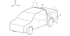
- FIG. 2 is a perspective view of a vehicle having the vehicle packing box of FIG. 1
- 2 is an enlarged view of a reinforcing member provided in the reinforcing structure of FIG. 1
- FIG. 4 is an exploded perspective view of the reinforcing member, the header board, and the side gate shown in FIG. 3 .
- the definition of directions is that the front-rear direction (vehicle length direction) is defined based on the forward and backward direction of the vehicle, and the left-right direction (vehicle width direction) is defined based on the front-rear direction.
- the up-down direction is defined based on the state in which the vehicle is stopped on a flat road surface.
- FR, UP, and LH respectively indicate the front, top, and left of the vehicle.
- the vehicle width direction in the part to the left of the vehicle body centerline in a top view of the vehicle, the left is the outside of the vehicle and the right is the inside of the vehicle.
- the right is the outside of the vehicle and the left is the inside of the vehicle.
- the structure of a vehicle is often formed to be almost symmetrical (mirror symmetry with respect to a plane including the yaw axis and roll axis that pass through the center of gravity of the vehicle), but it is not necessary for the shape to be completely symmetrical.
- this vehicle cargo box reinforcing structure can be applied to, for example, gasoline vehicles, electric vehicles (EVs), hybrid vehicles (Hybrid Electric Vehicles, HEVs), plug-in hybrid vehicles (Plug-in Hybrid Electric Vehicles, PHEVs), etc.
- EVs electric vehicles
- HEVs hybrid vehicles
- plug-in hybrid vehicles Plug-in Hybrid Electric Vehicles, PHEVs
- FIG. 1 is a perspective view of a vehicle cargo box 3 to which a reinforcing structure according to an embodiment is applied
- Fig. 2 is a perspective view of a vehicle 1 equipped with this vehicle cargo box 3.
- the vehicle 1 is provided with a cabin 2 (vehicle compartment) in which passengers board, and a vehicle cargo box 3 capable of accommodating luggage.
- the vehicle cargo box 3 is disposed behind the cabin 2, i.e., at the rear of the vehicle 1.
- the vehicle 1 of this embodiment has a ladder frame type chassis structure, and the vehicle cargo box 3 is mounted on a ladder frame (not shown).
- a ladder frame is a ladder-shaped frame that is made up of a pair of left and right side members that extend in the front-rear direction and a cross member that connects these side members in the vehicle width direction.
- the vehicle cargo box 3 has a floor panel 4 with a roughly rectangular bottom when viewed from above, and four walls 5, 6L, 6R, 7 along the front, rear, left and right edges of the floor panel 4.
- the walls 5-7 are a front header board 5, a pair of left and right side gates 6L, 6R, and a rear tailgate 7.
- the vehicle cargo box 3 is defined by the floor panel 4 and the four walls 5, 6L, 6R, 7, and has a flat, box-shaped storage space that is open at the top as a whole.
- the vehicle cargo box 3 is capable of storing luggage within this storage space.
- each side gate 6L, 6R is wall-like members erected on the left and right ends of the vehicle cargo box 3. Specifically, each side gate 6L, 6R extends in the vertical direction and in the longitudinal direction of the vehicle to form the side wall surface of the vehicle cargo box 3, and is disposed in a crossing position with respect to the header board 5.
- each side gate 6L, 6R includes a side outer panel 60 that forms the exterior of the vehicle cargo box 3, and a side inner panel 61 that is disposed inside the side outer panel 60 at a predetermined distance and forms the inner surface of the vehicle cargo box 3.
- the side outer panel 60 and the side inner panel 61 are fixed to each other by welding, for example, with their edges overlapping each other.
- the tailgate 7 is a door-shaped (wall-shaped) member erected at the rear end of the vehicle cargo box 3. Specifically, the tailgate 7 extends in the vehicle width direction and the vertical direction, and forms the rear wall surface of the vehicle cargo box 3.
- the tailgate 7 is provided so as to be rotatable in the front-rear direction, for example, around the central axis near its lower end edge.
- the header board 5 extends in the vehicle width direction and the vertical direction, and is a member that forms the front wall surface of the vehicle cargo box 3. As shown by the dashed line in Figure 2, the header board 5 is positioned immediately behind the rear surface of the cabin 2 with a gap.
- the header board 5 has cutout portions 50 formed by cutting out the lower left and lower right corners to ensure wheel housing for the rear wheels of the vehicle. In other words, each cutout portion 50 is provided at the position of the lower left corner and the position of the lower right corner of the header board 5.
- Each cutout 50 is defined by a first edge 51 and a second edge 52.
- the first edge 51 is part of the edge of the cutout 50 and extends upward from the lower end of the header board 5.
- the second edge 52 is the other part of the edge of the cutout 50 and extends outward in the vehicle width direction from the upper end of the first edge 51 above the lower end of the header board 5.
- the first edge 51 extending in the vertical direction and the second edge 52 extending in the vehicle width direction are both straight, and each cutout 50 is roughly L-shaped when viewed from the front.
- the header board 5 has a step portion 54 formed on the board surface bulging forward (front-rear direction) of the vehicle on the inner side in the vehicle width direction from the first edge portion 51.
- the step portion 54 is formed in the vertical direction from the lower end of the header board 5.
- the step portion 54 shown in FIG. 1 is provided near the cutout portion 50 and extends upward beyond the upper end of the first edge portion 51.
- the step portion 54 increases the rigidity of the header board 5 and improves the appearance of the header board 5.
- the reinforcing structure of this embodiment is applied to a vehicle cargo box 3 having a header board 5 with cutouts 50 at the lower left and right corners as described above.
- This reinforcing structure includes a reinforcing member 10 that is overlapped and fixed to the header board 5.
- the reinforcing member 10 is a plate-like member that is provided to correspond to each of the cutouts 50 at the lower left and lower right. In other words, a pair of reinforcing members 10 is provided on the left and right.
- Each reinforcing member 10 is preferably formed from a plate material that is thicker than the header board 5.
- Each of the left and right reinforcing members 10 has a first surface 11 extending along the first edge 51 of the cutout 50 and a second surface 12 extending along the second edge 52 of the cutout 50.
- first surface 11 extending along the first edge 51 means that the first surface 11 extends in the direction in which the first edge 51 extends (i.e., the vertical direction), and does not necessarily overlap with the first edge 51.
- second surface 12 extending along the second edge 52 means that the second surface 12 extends in the direction in which the second edge 52 extends (i.e., the vehicle width direction), and does not necessarily overlap with the second edge 52.
- a reinforcing member 10 in which the first surface 11 and the second surface 12 are integrally formed from a single plate-like member is exemplified.
- Figure 3 is an enlarged view of the left reinforcing member 10, and Figure 4 is an exploded perspective view of the left reinforcing member 10, the lower left end of the header board 5, and the side inner panel 61 (side gate 6L).
- the two reinforcing members 10, the left and right side gates 6L, 6R, and the lower left and right ends of the header board 5 may all be configured symmetrically.
- the following explanation will provide a detailed description of the configuration on the left side (reinforcing member 10, side gate 6L, and lower left end of the header board 5), and will omit an explanation of the configuration on the right side.
- the reinforcing member 10 has the first surface 11 and the second surface 12, and is formed in a generally L-shape in front view. That is, in the reinforcing member 10 of this embodiment, the upper end of the first surface 11 and the inner end of the second surface 12 in the vehicle width direction are formed continuously.
- the outer edge (left edge) of the first surface 11 in the vehicle width direction is positioned so as to substantially overlap the first edge 51, and extends above the second edge 52.
- the first surface 11 of this embodiment overlaps the plate surface of the header board 5 over the region from the first edge 51 to the outer ridge 54a in the vehicle width direction of the step portion 54 that is positioned adjacent to the inner side of the first edge 51 in the vehicle width direction.
- the second surface 12 is a surface that extends outward in the vehicle width direction from the outer edge (left edge) in the vehicle width direction at the upper part of the first surface 11.
- the lower edge of the second surface 12 on the inner side in the vehicle width direction overlaps with the second edge 52, but the lower edge on the outer side in the vehicle width direction is located above the second edge 52.
- the second surface 12 has a tapered shape in which the vertical dimensions become smaller as it goes outward in the vehicle width direction.
- the upper edge of the second surface 12 is appropriately set at a height position that ensures a sufficient area when it is overlapped and fixed to the header board 5.
- a third surface portion 13 is provided continuously from the first surface portion 11 toward the inside (right side) in the vehicle width direction.
- the third surface portion 13 is a portion that is overlapped and fixed to a part of the step portion 54, and bulges toward the front of the vehicle along the shape of the step portion 54 and extends in the vertical direction.
- the third surface portion 13 of this embodiment is provided in a predetermined range above and below the step portion 54 extending in the vertical direction, adjacent to a corner portion 53 (broken line in FIG. 3) of the cutout portion 50 described later.
- the outer edge (left edge) of the third surface portion 13 in the vehicle width direction is continuous with the first surface portion 11.
- the inner edge (right edge, edge opposite the first surface portion 11) of the third surface portion 13 in the vehicle width direction is provided along the inner ridge line 54b of the step portion 54 in the vehicle width direction and beyond this ridge line 54b on the inside in the vehicle width direction.
- the upper edge of the third surface portion 13 is arranged to be continuous with the upper edge of the first surface portion 11 (or the upper edge of the second surface portion 12).
- the reinforcing member 10 of this embodiment has a fourth surface 14 between the first surface 11 and the second surface 12, which protrudes downward from the second edge 52 of the cutout portion 50.
- the header board 5 has a corner 53 formed by the first edge 51 and the second edge 52, which is formed in an arc shape.
- a rounded corner (corner R) is formed at the corner 53.
- This corner 53 is a portion defined by the upper end of the first edge 51 and the inner end (right end) of the second edge 52 in the vehicle width direction, and is formed by cutting out a part of the second edge 52 in a curved shape (arc shape).
- the fourth surface 14 of the reinforcing member 10 is arranged to overlap the corner 53 that forms this rounded corner.
- the rounded corner of the corner portion 53 is formed by cutting out a portion of the second edge portion 52 in a curved shape, but the shape of the corner portion 53 is not limited to this.
- the corner portion 53 may be formed in an arc shape by cutting out a portion of the first edge portion 51, or the first edge portion 51 and the second edge portion 52 in a curved shape.
- the fourth surface portion 14 is disposed in front of this corner portion 53. Therefore, of the reinforcing member 10, only the fourth surface portion 14 does not directly overlap the header board 5, but is located in the space (inside the cutout portion 50).
- the reinforcing member 10 is overlapped on the front surface of the header board 5 and fixed to the header board 5, for example, by spot welding. However, the reinforcing member 10 is partially fixed to both the header board 5 and the side inner panel 61 (side gate 6L). That is, the reinforcing member 10 is positioned in front of the header board 5, the front end of the side inner panel 61 is positioned behind the header board 5, and the reinforcing member 10 is also partially fixed to the side inner panel 61 with the header board 5 in between.
- a flange portion 62 extending in the vehicle width direction and the vertical direction is provided at the front end of the side inner panel 61.
- the flange portion 62 is formed in a shape that makes surface contact with the first edge portion 51 and the second edge portion 52 of the header board 5.
- a flange portion 62 including a first flange portion 62a that makes surface contact with the first edge portion 51 and a second flange portion 62b that makes surface contact at a position slightly above the second edge portion 52 is shown.
- the first surface portion 11, the first edge portion 51, and the first flange portion 62a are welded and fixed in a triple-layered state.
- multiple (e.g., three) spot points are arranged in parallel in the vertical direction along the first edge portion 51.
- the lower edge side of the second surface portion 12, the upper part of the second edge portion 52, and the second flange portion 62b are welded and fixed in a triple-layered state.
- multiple (e.g., three) spot points are arranged in parallel in the vehicle width direction along the second edge portion 52.
- the second surface portion 12 in this embodiment is shaped so that its lower edge is positioned slightly above the second edge portion 52 so as to be aligned with the spot points with the second flange portion 62b.
- the reinforcing member 10 is fixed only to the header board 5 on the upper edge side of the second surface 12 and on the inner side (right side) of the third surface 13 in the vehicle width direction.
- the third surface 13 is provided with a plurality of spot impact points along the ridge line 54b of the step portion 54.
- a plurality of spot impact points are arranged in parallel in the vehicle width direction to connect the impact point located furthest outward in the vehicle width direction among the impact points on the lower edge side of the second surface 12 and the uppermost impact point among the impact points on the third surface 13.
- a mounting hole 15 is provided through the fourth surface 14 of the reinforcing member 10.
- the mounting hole 15 is a hole provided for mounting a separate member other than the vehicle cargo box 3.
- An example of the separate member is a bracket for mounting a fuel supply pipe.
- a fuel supply port 70 is provided on the side gate 6L, and a fuel supply pipe may be disposed near the lower left of the header board 5. Therefore, the mounting hole 15 is suitable as an attachment position for a bracket for fixing the fuel supply pipe to the vehicle body.
- the header board 5 has cutouts 50 at the left and right lower corners
- the vehicle cargo box 3 has a reinforcement member 10 having a first surface 11 and a second surface 12 extending along the first edge 51 and the second edge 52 that define the cutout 50.
- the first surface 11 and the second surface 12 of the reinforcement member 10 are overlapped and fixed to the edges (i.e., the first edge 51 and the second edge 52) of the cutout 50 of the header board 5. Therefore, the edges 51 and 52 that constitute the cutout 50 can be reinforced by the reinforcement member 10. This increases the rigidity around the cutout 50 of the header board 5, thereby suppressing forward and backward shaking and mitigating stress concentration in the header board 5 having the cutout 50.
- the first surface portion 11 and the second surface portion 12 are integrally formed, so that the rigidity around the cutout portion 50 can be increased with a simple configuration, and the forward and backward shaking of the header board 5 can be effectively suppressed.
- the header board 5 described above has a step portion 54 formed in the vertical direction on the inner side of the first edge portion 51 of the cutout portion 50 in the vehicle width direction, the plate surface of which bulges in the vehicle front-rear direction. This increases the rigidity of the header board 5 due to the step portion 54.
- the step portion 54 since the step portion 54 is provided near the cutout portion 50, the step portion 54 can become a stress concentration point when the header board 5 sways back and forth.
- the third surface portion 13 of the reinforcement member 10 is overlapped and fixed to a part of the step portion 54. Therefore, the reinforcement member 10 can reinforce the area from the cutout portion 50 to the step portion 54. This makes it possible to more effectively suppress the header board 5 from swaying back and forth.
- the reinforcing member 10 described above has a fourth surface portion 14 that protrudes downward from the second edge portion 52 of the cutout portion 50, the area of the reinforcing member 10 can be increased. This can improve the ability to suppress forward and backward swaying of the header board 5.
- the fourth surface 14 is provided so as to overlap the corner 53 of the cutout 50.
- the corner 53 is a portion where stress is particularly likely to concentrate, but the fourth surface 14 of the reinforcing member 10 can alleviate the stress concentrated at the corner 53 of the cutout 50. As a result, the forward and backward shaking of the header board 5 can be effectively suppressed.
- the corners 53 of the cutouts 50 of the header board 5 are formed in an arc shape. Therefore, in addition to the reinforcing effect of the reinforcement members 10, the shape of the header board 5 itself can also alleviate stress concentration. Therefore, the forward and backward shaking of the header board 5 can be more effectively suppressed.
- the fourth surface 14 of the reinforcement member 10 is provided with mounting holes 15 for mounting a separate member, so that the reinforcement member 10 can also function as a mounting fixture for the separate member. Therefore, for example, a separate member (such as a bracket for suspending an oil supply pipe) that was previously directly attached to the header board 5 can now be attached to the fourth surface 14. This eliminates the need to process the header board 5 itself for mounting a separate member, allowing for greater freedom in terms of the shape and layout of the header board 5.
- a flange portion 62 that comes into surface contact with the first edge portion 51 and the second edge portion 52 of the header board 5 is provided at the front end portion of the side gates 6L, 6R, and the first surface portion 11 and the second surface portion 12 of the reinforcing member 10 are fixed to the flange portion 62 of the side gates 6L, 6R, sandwiching the first edge portion 51 and the second edge portion 52 of the header board 5. Therefore, even if the luggage in the vehicle cargo box 3 moves during driving and hits the header board 5, the header board 5 can be prevented from moving away from the side gates 6L, 6R, causing a so-called "open mouth.”
- the above-mentioned reinforcing structure of the vehicle cargo box 3 is merely an example, and is not limited to the above.
- the third surface 13 and the fourth surface 14 of the reinforcing member 10 are not essential and may be omitted. Even when the fourth surface 14 is provided, the fourth surface 14 may be located at a position that does not overlap with the corner portion 53.
- the mounting hole 15 extending through the fourth surface 14 is also not essential and may be omitted.
- the shapes of the first surface 11 and the second surface 12 of the reinforcing member 10 are not limited to those described above.
- the second surface 12 may be shaped to overlap the second edge 52 over the entire width of the vehicle.
- the first surface 11 and the second surface 12 may not be formed continuously, but may be separated.
- the reinforcing member 10 does not have to be a single piece.
- the reinforcing member 10 may not be fixed to the side gates 6L, 6R (flange portions 62) but only to the header board 5.
- the method of fixing the reinforcing member 10 to the header board 5 (or flange portions 62) is not limited to spot welding, and even in the case of spot welding, the position, number, and configuration of the welding points are not limited to those described above.
- the configuration of the vehicle cargo box 3 and the configuration of the header board 5 are also examples.
- the step portion 54 of the header board 5 is not limited to one that bulges toward the front of the vehicle, but may be one that bulges toward the rear of the vehicle, or the header board 5 may have no step portion 54.
- the corner portion 53 formed by the first edge portion 51 and the second edge portion 52 of the header board 5 does not have to be a round corner. Note that even if the reinforcing member 10 is not fixed to the side gates 6L, 6R, the header board 5 needs to be fixed to the side gates 6L, 6R, so the flange portion 62 needs to be provided, but the shape and arrangement of the flange portion 62 are not limited to those described above.
- This invention can be used in the manufacturing industry of vehicles with cargo boxes, as well as in the manufacturing industry of vehicle cargo boxes and the manufacturing industry of vehicle body structures around cargo boxes.
Landscapes
- Engineering & Computer Science (AREA)
- Chemical & Material Sciences (AREA)
- Combustion & Propulsion (AREA)
- Transportation (AREA)
- Mechanical Engineering (AREA)
- Body Structure For Vehicles (AREA)
Abstract
Description
態様3.上記の態様1又は2において、前記ヘッダーボードには、前記切り欠き部の前記第一縁部よりも車幅方向の内側において板面を車両前後方向へ膨出してなる段差部が上下方向に沿って形成されていることが好ましい。この場合、前記補強部材は、前記段差部の一部に重ね合わされて固定される第三面部を有することが好ましい。
態様5.上記の態様4において、前記第四面部は、前記第一縁部と前記第二縁部とで形成される隅部に重複して配置されていることが好ましい。
態様6.上記の態様5において、前記第四面部が位置する前記隅部は弧状に形成されていることが好ましい。
態様7.上記の態様4~6の何れかにおいて、前記補強部材は、前記第四面部に貫設され、前記車両荷箱ではない別部材を取り付けるための取付孔を有することが好ましい。
図1は、実施例としての補強構造が適用された車両荷箱3の斜視図であり、図2は、この車両荷箱3を備えた車両1の斜視図である。図2に示すように、車両1には、乗員が搭乗するキャビン2(車室)と、荷物を収容可能な車両荷箱3とが設けられる。車両荷箱3はキャビン2の後方、すなわち車両1の後部に配置される。
(1)上述したように、ヘッダーボード5の左右下端の角部が切り欠かれた車両荷箱3の構造では、車両走行中の振動や、車両荷箱3内に収容された荷物が走行中にぶつかる等の外力により、ヘッダーボード5が前後に揺れたり変形したりしたときに、切り欠き部50に応力が集中しやすい傾向がある。切り欠き部50に応力が集中すると、切り欠き部50に亀裂や変形が生じうる。
上述した車両荷箱3の補強構造は一例であって、上述したものに限られない。
例えば、補強部材10の第三面部13及び第四面部14は必須ではなく省略可能である。第四面部14を設ける場合であっても、第四面部14が隅部53と重複しない位置であってもよい。また、第四面部14に貫設された取付孔15も必須ではなく省略可能である。
2 キャビン
3 車両荷箱
4 フロアパネル
5 ヘッダーボード
6L,6R サイドゲート
7 テールゲート
10 補強部材
11 第一面部
12 第二面部
13 第三面部
14 第四面部
15 取付孔
50 切り欠き部
51 第一縁部
52 第二縁部
53 隅部
54 段差部
54a,54b 稜線
60 サイドアウターパネル
61 サイドインナーパネル
62 フランジ部
62a 第一フランジ部
62b 第二フランジ部
70 給油口
Claims (8)
- 車両の後部に配置される車両荷箱の補強構造であって、
前記車両荷箱には、車幅方向及び上下方向に延在する前壁面をなすヘッダーボードと、前記車両荷箱の左右側端部に立設された壁状のサイドゲートと、が設けられ、
前記ヘッダーボードの左下及び右下の角部の位置にはそれぞれ、前記ヘッダーボードの下端から上方へ延びた第一縁部と、前記下端よりも上側において前記第一縁部の上端から車幅方向外側へ延びた第二縁部とで画成された切り欠き部が設けられており、
前記補強構造は、前記第一縁部に沿って延在する第一面部と前記第二縁部に沿って延在する第二面部とを有するとともに前記ヘッダーボードに重ね合わされて固定される補強部材を備えた
ことを特徴とする、車両荷箱の補強構造。 - 前記補強部材は、前記第一面部と前記第二面部とが一体で形成された
ことを特徴とする、請求項1記載の車両荷箱の補強構造。 - 前記ヘッダーボードには、前記切り欠き部の前記第一縁部よりも車幅方向の内側において板面を車両前後方向へ膨出してなる段差部が上下方向に沿って形成されており、
前記補強部材は、前記段差部の一部に重ね合わされて固定される第三面部を有する
ことを特徴とする、請求項1又は2記載の車両荷箱の補強構造。 - 前記補強部材は、前記切り欠き部の前記第二縁部よりも下方へ突設された第四面部を有する
ことを特徴とする、請求項1~3のいずれか一項に記載の車両荷箱の補強構造。 - 前記第四面部は、前記第一縁部と前記第二縁部とで形成される隅部に重複して配置された
ことを特徴とする、請求項4記載の車両荷箱の補強構造。 - 前記第四面部が位置する前記隅部は弧状に形成されている
ことを特徴とする、請求項5記載の車両荷箱の補強構造。 - 前記補強部材は、前記第四面部に貫設され、前記車両荷箱ではない別部材を取り付けるための取付孔を有する
ことを特徴とする、請求項4~6のいずれか一項に記載の車両荷箱の補強構造。 - 前記サイドゲートの前端部には、車幅方向及び上下方向に延在し前記ヘッダーボードの前記第一縁部及び前記第二縁部と面接触するフランジ部が設けられ、
前記補強部材の前記第一面部及び前記第二面部はそれぞれ、前記ヘッダーボードの前記第一縁部及び前記第二縁部を挟んで前記サイドゲートの前記フランジ部に固定された
ことを特徴とする、請求項1~7のいずれか一項に記載の車両荷箱の補強構造。
Priority Applications (2)
| Application Number | Priority Date | Filing Date | Title |
|---|---|---|---|
| PCT/JP2023/013524 WO2024201996A1 (ja) | 2023-03-31 | 2023-03-31 | 車両荷箱の補強構造 |
| JP2025509584A JPWO2024201996A1 (ja) | 2023-03-31 | 2023-03-31 |
Applications Claiming Priority (1)
| Application Number | Priority Date | Filing Date | Title |
|---|---|---|---|
| PCT/JP2023/013524 WO2024201996A1 (ja) | 2023-03-31 | 2023-03-31 | 車両荷箱の補強構造 |
Publications (1)
| Publication Number | Publication Date |
|---|---|
| WO2024201996A1 true WO2024201996A1 (ja) | 2024-10-03 |
Family
ID=92904491
Family Applications (1)
| Application Number | Title | Priority Date | Filing Date |
|---|---|---|---|
| PCT/JP2023/013524 Ceased WO2024201996A1 (ja) | 2023-03-31 | 2023-03-31 | 車両荷箱の補強構造 |
Country Status (2)
| Country | Link |
|---|---|
| JP (1) | JPWO2024201996A1 (ja) |
| WO (1) | WO2024201996A1 (ja) |
Citations (3)
| Publication number | Priority date | Publication date | Assignee | Title |
|---|---|---|---|---|
| JPH08276865A (ja) * | 1995-04-04 | 1996-10-22 | Kanto Auto Works Ltd | リヤサスペンションタワーまわりの補強構造 |
| JPH09240510A (ja) * | 1996-03-12 | 1997-09-16 | Nissan Motor Co Ltd | 自動車の車体後部構造 |
| JP2002211447A (ja) * | 2000-12-21 | 2002-07-31 | Hyundai Motor Co Ltd | スポーツユーティリティートラックのミッドゲート設置構造 |
-
2023
- 2023-03-31 WO PCT/JP2023/013524 patent/WO2024201996A1/ja not_active Ceased
- 2023-03-31 JP JP2025509584A patent/JPWO2024201996A1/ja active Pending
Patent Citations (3)
| Publication number | Priority date | Publication date | Assignee | Title |
|---|---|---|---|---|
| JPH08276865A (ja) * | 1995-04-04 | 1996-10-22 | Kanto Auto Works Ltd | リヤサスペンションタワーまわりの補強構造 |
| JPH09240510A (ja) * | 1996-03-12 | 1997-09-16 | Nissan Motor Co Ltd | 自動車の車体後部構造 |
| JP2002211447A (ja) * | 2000-12-21 | 2002-07-31 | Hyundai Motor Co Ltd | スポーツユーティリティートラックのミッドゲート設置構造 |
Also Published As
| Publication number | Publication date |
|---|---|
| JPWO2024201996A1 (ja) | 2024-10-03 |
Similar Documents
| Publication | Publication Date | Title |
|---|---|---|
| US10518621B2 (en) | Vehicle rear structure | |
| US8764104B2 (en) | Structure of front section of vehicle body | |
| US11192592B2 (en) | Upper vehicle-body structure | |
| JP2019202747A (ja) | 車体下部構造体 | |
| JP5352740B2 (ja) | 車体前部構造 | |
| JP6489140B2 (ja) | 車両の下部車体構造 | |
| JP4918153B2 (ja) | 車体前部構造 | |
| US12420868B2 (en) | Rear structure of vehicle body | |
| JP2021046166A (ja) | 車体前部構造 | |
| JP2021138302A (ja) | 車両の側部車体構造 | |
| US20210237801A1 (en) | Body of vehicle | |
| JP7264091B2 (ja) | 車両の側部車体構造 | |
| US12187355B2 (en) | Lower vehicle-body structure of vehicle | |
| JP2021138301A (ja) | 車両の側部車体構造 | |
| WO2024201996A1 (ja) | 車両荷箱の補強構造 | |
| JP3537669B2 (ja) | 自動車の車体下側部補強構造 | |
| WO2019198751A1 (ja) | 自動車の車体構造 | |
| JP2024081059A (ja) | 車両後部バッテリ搭載構造 | |
| JP5496727B2 (ja) | 自動車の前部車体構造 | |
| CN115257958A (zh) | 车辆的下部车身结构 | |
| JP7235191B1 (ja) | 車両荷箱の補強構造 | |
| CN116575819B (zh) | 铰链安装加强板总成、铰链安装系统以及车辆 | |
| JP5934168B2 (ja) | 車体後部構造 | |
| JP7240644B2 (ja) | 車両のダッシュパネル及び車両のダッシュパネル取付構造 | |
| JP6010804B2 (ja) | 車両前部構造 |
Legal Events
| Date | Code | Title | Description |
|---|---|---|---|
| 121 | Ep: the epo has been informed by wipo that ep was designated in this application |
Ref document number: 23930631 Country of ref document: EP Kind code of ref document: A1 |
|
| ENP | Entry into the national phase |
Ref document number: 2025509584 Country of ref document: JP Kind code of ref document: A |
|
| WWE | Wipo information: entry into national phase |
Ref document number: 2025509584 Country of ref document: JP |
|
| NENP | Non-entry into the national phase |
Ref country code: DE |
|
| 122 | Ep: pct application non-entry in european phase |
Ref document number: 23930631 Country of ref document: EP Kind code of ref document: A1 |