WO2024201958A1 - 車両用ダクトの配管構造 - Google Patents
車両用ダクトの配管構造 Download PDFInfo
- Publication number
- WO2024201958A1 WO2024201958A1 PCT/JP2023/013405 JP2023013405W WO2024201958A1 WO 2024201958 A1 WO2024201958 A1 WO 2024201958A1 JP 2023013405 W JP2023013405 W JP 2023013405W WO 2024201958 A1 WO2024201958 A1 WO 2024201958A1
- Authority
- WO
- WIPO (PCT)
- Prior art keywords
- duct
- vehicle
- air conditioning
- exhaust heat
- seat
- Prior art date
- Legal status (The legal status is an assumption and is not a legal conclusion. Google has not performed a legal analysis and makes no representation as to the accuracy of the status listed.)
- Ceased
Links
Images


Classifications
-
- B—PERFORMING OPERATIONS; TRANSPORTING
- B60—VEHICLES IN GENERAL
- B60H—ARRANGEMENTS OF HEATING, COOLING, VENTILATING OR OTHER AIR-TREATING DEVICES SPECIALLY ADAPTED FOR PASSENGER OR GOODS SPACES OF VEHICLES
- B60H1/00—Heating, cooling or ventilating devices
Definitions
- This disclosure relates to the piping structure of a vehicle duct.
- Patent Document 1 discloses an electric vehicle with a driving battery pack installed inside the vehicle cabin.
- an air conditioning duct is arranged in the front-to-rear direction between the right and left seats, and the battery pack is installed on the vehicle floor between the right and left seats.
- the battery pack has a battery case and a battery module arranged inside the battery case, and the air conditioning duct is arranged along the outer periphery of the battery case.
- the electric vehicle may be a plug-in hybrid vehicle that can be externally charged by an external power source or externally powered from the driving battery pack.
- the battery pack since the battery pack generates heat due to power supply etc., it is preferable to actively dissipate heat from the perspective of protecting the battery module.
- the structure is such that heat is dissipated below the seat as in Patent Document 1, the hot air discharged from the battery pack will fill the area around the passenger's feet, which may cause discomfort to the passenger.
- the battery pack needs to be made larger, but if a blower fan and a duct for dissipating heat are placed to the side of the battery pack, the installation space for the battery pack will be reduced accordingly, so there is room for improvement in the installation positions of the blower fan and heat exhaust duct when the battery pack is installed inside the vehicle cabin.
- At least one embodiment of the present invention aims to provide a duct piping structure for a vehicle that can effectively utilize the space inside the vehicle cabin by consolidating the battery pack's heat exhaust duct and the air conditioning duct of the air conditioning unit while reducing discomfort caused by the exhaust heat emitted from the battery pack.
- the piping structure of a vehicle duct includes an exhaust heat duct that extends in the fore-and-aft direction of the vehicle from a blower fan provided above a battery pack that is installed above a floor panel that constitutes the floor surface of the vehicle compartment, passing between a right seat and a left seat that are arranged side by side in the vehicle width direction, and extending from the right seat and the left seat to a position far in front or rear of the vehicle compartment, an air conditioning duct that extends in the fore-and-aft direction of the vehicle from an air conditioning device, passing between the right seat and the left seat, and a floor console that extends in the fore-and-aft direction of the vehicle between the right seat and the left seat and covers the exhaust heat duct and the air conditioning duct, and the exhaust heat duct and the air conditioning duct are installed side by side in the vehicle height direction within the floor console so that the air conditioning duct is located above the exhaust heat duct.
- the exhaust heat duct for the battery pack and the air conditioning duct for the air conditioner are concentrated and piped in the floor console between the right seat (driver's seat) and the left seat (passenger seat), and the exhaust heat duct is extended to a position away from both the left and right seats, so that the exhaust heat of the battery pack can be discharged at a position away from the seats.
- the exhaust heat duct is located below the air conditioning duct in the floor console, the hot air released from the exhaust heat duct can be blocked by the floor console and the air conditioning duct, preventing the heat from being transmitted to the interior of the vehicle outside the floor console (particularly the upper side). This makes it possible to pipe the exhaust heat duct and the air conditioning duct by effectively utilizing the space in the vehicle interior while reducing discomfort to occupants due to exhaust heat.
- a heat shield is provided between the exhaust heat duct and the air conditioning duct.
- the above configuration (2) can suppress the transfer of heat from the air flowing through the exhaust heat duct to the air flowing through the air conditioning duct, thereby suppressing deterioration of the air conditioning performance for the rear seats.
- the heat shield has an upper plate portion that is positioned between the air conditioning duct and covers the upper side of the exhaust heat duct, and side plate portions that extend downward from both ends of the upper plate portion in the vehicle width direction and cover the sides of the exhaust heat duct.
- the above configuration (3) surrounds the exhaust heat duct from above and from the sides, so that the hot air emitted from the exhaust heat duct can be more reliably insulated, and therefore, heat dissipation into the passenger compartment and heat transfer to the air conditioning duct can be more reliably suppressed.
- the configuration of (2) above includes a console base for mounting the floor console, and the heat shield is provided on the console base.
- the heat shield is attached to the console base, so there is no need to provide a separate member for attaching the heat shield.
- the exhaust heat duct and the air conditioning duct are attached to the console base.
- the air conditioning duct is attached to the console base, so there is no need to provide a separate member for attaching the air conditioning duct.
- the console base has a support plate portion for supporting an on-board component (selector lever) installed on the floor console, the air conditioning duct passes below the support plate portion and extends in the fore-and-aft direction of the vehicle, and the heat shield is located below the support plate portion and extends between the exhaust heat duct and the air conditioning duct, and the exhaust heat duct is attached to the heat shield.
- the air conditioning duct passes below the support plate portion and extends in the fore-and-aft direction of the vehicle
- the heat shield is located below the support plate portion and extends between the exhaust heat duct and the air conditioning duct, and the exhaust heat duct is attached to the heat shield.
- the above configuration (6) allows the air conditioning duct and the heat exhaust duct to be efficiently arranged in the space within the floor console.
- the battery pack is installed under both the right seat and the left seat, the blower fan is provided above the battery pack between the right seat and the left seat and is also disposed in the floor console, and the air conditioning duct is extended above the exhaust heat duct and the blower fan.
- the above configuration (7) allows for the exhaust heat duct, blower fan, and air conditioning duct to be concentrated within the floor console in an electric vehicle in which the battery packs are installed under the right seat (driver's seat) and the left seat (passenger's seat), making it possible to more effectively utilize the space inside the vehicle cabin while further reducing discomfort to passengers caused by exhaust heat.
- FIG. 1 is a diagram showing a schematic view of the interior of a vehicle cabin in which a piping structure for a vehicle duct according to an embodiment is adopted; 1 is a longitudinal sectional view showing a vehicle in which a piping structure for a vehicle duct according to an embodiment is adopted; 3 is a cross-sectional view of the vehicle duct piping structure shown in FIG. 2 taken along line III-III. 4 is a cross-sectional view of the vehicle duct piping structure shown in FIG. 2 taken along line IV-IV.
- FIG. 3 is a perspective view of the piping structure of the vehicle duct shown in FIG. 2 .
- FIG. 6 is an exploded perspective view of the piping structure of the vehicle duct shown in FIG. 5 .
- expressions expressing shapes such as a square or cylindrical shape not only express shapes such as a square or cylindrical shape in the strict geometric sense, but also express shapes including uneven parts and chamfered parts to the extent that the same effect is obtained.
- expressions such as “comprise,” “include,” “include,” “include,” or “have” one component are not exclusive expressions that exclude the existence of other components.
- FIG. 1 is a diagram showing a schematic view of the interior of a vehicle 100 in which the vehicle duct piping structure according to the embodiment is adopted.
- the vehicle 100 in which the vehicle duct piping structure according to the embodiment is adopted is a vehicle in which an instrument panel 106 is provided in front of a right seat (driver's seat) 102 and a left seat (passenger's seat) 104 arranged side by side in the vehicle width direction, a floor console 108 is provided between the right seat 102 and the left seat 104, and a console box 110 is provided behind the floor console 108 in the vehicle front-rear direction.
- the floor console 108 is a part that combines design and utility, and ducts and harnesses are installed inside the floor console 108, and a selector lever 112 and various switches 114 are provided on the upper surface of the floor console 108.
- the console box 110 has an armrest 116 on its upper surface, and an air outlet 118 for conditioned air is provided on its rear side.
- the vehicle 100 in which the vehicle duct piping structure 1 according to the embodiment is mounted is an electric vehicle in which a battery pack 120 is mounted in the vehicle cabin, and is a hybrid vehicle (HV, HEV) in which the drive wheels are driven by at least one of a drive motor or an engine, but is not limited thereto, and may be an electric vehicle (EV) in which the drive wheels are driven by a drive motor.
- HV hybrid vehicle
- EV electric vehicle
- the hybrid vehicle according to the embodiment is a plug-in hybrid vehicle (PHV, PHEV) that can be charged (hereinafter referred to as “external charging”) from an external device (e.g., a quick charger) while stopped, and can supply power (hereinafter referred to as “external power supply”) from the outside (e.g., an ordinary household) while stopped, but is not limited thereto.
- PV plug-in hybrid vehicle
- PHEV plug-in hybrid vehicle
- the battery pack 120 is installed above a floor panel 122 that constitutes the floor of the vehicle compartment, and below the seats (seat cushions) of the right seat 102 and the left seat 104.
- the battery pack 120 is box-shaped, longer in the vehicle width direction than in the vehicle front-rear direction, and is installed in the center of the vehicle width direction so that the right seat side and the left seat side are equally divided. Duct openings are provided at both ends of the battery pack 120 in the vehicle width direction, and a blower fan 124 is provided above the battery pack 120.
- the blower fan 124 is for actively dissipating heat within the battery pack 120, and a fan duct 126 is provided between the blower fan 124 and the battery pack 120, but the blower fan 124 and the battery pack 120 may also be directly connected.
- the blower fan 124 is located above the battery pack 120, between the right seat 102 and the left seat 104, in the center of the vehicle width direction of the battery pack 120, and is also located in the floor console 108, with its outlet 128 opening toward the front of the vehicle.
- an air conditioner 130 is installed in the front of the passenger compartment.
- the air conditioner 130 is a device that controls the temperature, humidity, and air quality in the passenger compartment, and is known as an HVAC (Heating Ventilation Air Conditioning) device.
- the air conditioner 130 is disposed in front of the instrument panel 106 and is covered by the instrument panel 106.
- the vehicle duct piping structure 1 includes an exhaust heat duct 10 that passes between the right seat 102 and the left seat 104 from the blower fan 124 and extends to a position in front or behind the right seat 102 and the left seat 104 (for example, a position facing a dashboard 132 that separates the vehicle from the engine room), and an air conditioning duct 12 that passes between the right seat 102 and the left seat 104 from the air conditioning device 130 and extends in the front-rear direction of the vehicle (for example, rearward of the right seat 102).
- the exhaust heat duct 10 and the air conditioning duct 12 are installed side by side in the vehicle height direction within the floor console 108 so that the air conditioning duct 12 is located above the exhaust heat duct 10.
- the heat exhaust duct 10 is a duct with a rectangular cross section, with one end connected to the outlet 128 of the blower fan 124 and the other end opening at a position facing the dashboard 132, and is manufactured by, for example, but not limited to, blow molding.
- the heat exhaust duct 10 is provided such that the opening end 16, which opens at a position facing the dashboard 132, is lower in the vehicle height direction than the connection end 14, which is connected to the outlet 128 of the blower fan 124.
- the heat exhaust duct 10 is bent in the vehicle height direction between the connection end 14 and the opening end 16, and is inclined so as to gradually become higher toward the blower fan 124 just before the connection end 14.
- the exhaust heat duct 10 is installed, for example, on a backbone provided in the center of the floor panel 122 in the vehicle width direction, but if it is installed between the right seat 102 and the left seat 104, it is not necessary to provide a backbone on the floor panel 122.
- the air conditioning duct 12 is a duct with a rectangular cross section, one end of which is connected to the outlet of the air conditioning unit 130 and the other end of which opens rearward of the right seat 102 in the vehicle longitudinal direction, and the opening end 18 that opens rearward of the right seat 102 in the vehicle longitudinal direction is installed, for example, inside the console box 110.
- the air conditioning duct 12 is formed, for example, by connecting multiple ducts, but is not limited to this. Each of the multiple ducts is manufactured, for example, by blow molding, but is not limited to this.
- the exhaust heat duct 10 and the air conditioning duct 12 are installed in positions adjacent to the exhaust heat duct 10 vertically in the vehicle height direction.
- the air conditioning duct 12 is extended above the exhaust heat duct 10 and the blower fan 124.
- being adjacent to the exhaust heat duct 10 vertically also includes sandwiching something (for example, a heat shield 20 described below) between the exhaust heat duct 10 and the air conditioning duct 12.
- the duct piping structure 1 includes a heat shield plate 20 between the exhaust heat duct 10 and the air conditioning duct 12.
- the heat shield plate 20 may be made of synthetic resin or metal as long as it suppresses the transfer of heat between the air (heated air) flowing through the exhaust heat duct 10 and the air (cooled air) flowing through the air conditioning duct 12.
- FIG. 3 is a cross-sectional view of the vehicle duct piping structure 1 shown in FIG. 2 taken along line III-III
- FIG. 4 is a cross-sectional view of the vehicle duct piping structure 1 shown in FIG. 2 taken along line IV-IV.
- the exhaust heat duct 10 is attached to a heat shield plate 20.
- the exhaust heat duct 10 shown in FIG. 3 has a rectangular tubular cross section and is attached to a gutter-shaped heat shield plate 20 that is provided to cover the upper half of the exhaust heat duct 10.
- the exhaust heat duct 10 is provided with an attachment portion 22 that protrudes outward in the middle of the height direction, while the heat shield plate 20 is provided with an attachment receiving portion 24 that corresponds to the attachment portion 22 of the exhaust heat duct 10, and the clip 26 penetrates the attachment receiving portion 24 of the heat shield plate 20 and the attachment portion 22 of the exhaust heat duct 10, thereby attaching the exhaust heat duct 10 to the heat shield plate 20.
- the heat shield 20 has an upper plate portion 20a that is located between the air conditioning duct 12 and covers the upper side of the exhaust heat duct 10, and side plate portions 20b that extend downward from both ends of the upper plate portion 20a in the vehicle width direction and cover the sides of the exhaust heat duct 10.
- the side plate portions 20b are formed, for example, in a stepped shape and extend downward below the bottom surface of the exhaust heat duct 10 in the vehicle height direction.
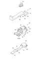
- FIG. 5 is a perspective view of the piping structure 1 of the vehicle duct shown in Fig. 2, and Fig. 6 is an exploded perspective view of the piping structure 1 of the vehicle duct shown in Fig. 5.
- the piping structure 1 of the vehicle duct includes a console base 28 for mounting the floor console 108 described above, and the heat shield plate 20 is provided on the console base 28.
- the console base 28 is a structure fixed to the floor panel 122 and is made of synthetic resin or metal.
- the console base 28 has a main body portion 30 provided so as to cover the blower fan 124 described above, and a heat shield portion 32 extending forward in the vehicle longitudinal direction from the main body portion 30.
- the main body 30 is gate-shaped with an opening on the surface facing the floor panel 122, and is fixed to the floor panel 122.
- the main body 30 has a support plate 34 for supporting an in-vehicle part installed on the floor console 108, and legs 36, 38 extending from the support plate 34 toward the floor panel 122.
- the in-vehicle part installed on the floor console 108 is, for example, a selector lever 112.
- the support plate 34 is a rectangular plate when viewed from above, and the legs 36, 38 extend from the four corners of the support plate 34 toward the floor panel 122.
- the legs 36, 38 are provided at the portions in contact with the floor panel 122 with seats 40, 42 for attaching the console base 28 to the floor panel 122.
- the seats 40, 42 are provided with through holes 44, 46, and the console base 28 is fixed to the floor panel 122 by screws passing through the through holes 44, 46.
- an arch-shaped side plate 48 is provided between the front leg 36, 38, which is provided at the front of the vehicle in the longitudinal direction, and the rear leg 38, which is provided behind the front leg 36.
- the heat shield 32 is a part that constitutes the heat shield 20 that is provided on the console base 28, and as described above, is formed in a gutter shape that covers the upper half of the exhaust heat duct 10, and is provided with an attachment portion 24 that corresponds to the attachment portion 22 of the exhaust heat duct 10.
- the console base 28 has an opening 50 between the main body 30 and the heat shield 32 through which the air conditioning duct 12 can be inserted.
- the air conditioning duct 12 passes below the support plate 34 and extends in the fore-and-aft direction of the vehicle.
- the air conditioning duct 12 is installed between the support plate 34 and the blower fan 124.
- the heat shielding portion 32 is located below the support plate portion 34 in the vehicle height direction and extends between the exhaust heat duct 10 and the air conditioning duct 12, to which the exhaust heat duct 10 is attached.
- Through holes 52, 54 are provided on the sides of the front legs 36 and the rear legs 38, respectively, and the air conditioning duct 12 is attached to the console base 28 by inserting clips 56, 58 through these through holes 52, 54 and into through holes 64, 66 formed in mounting parts 60, 62 provided on the air conditioning duct 12.
- the exhaust heat duct 10 of the battery pack 120 and the air conditioning duct 12 of the air conditioner 130 are integrated and piped in the floor console 108 between the right seat (driver's seat) 102 and the left seat (passenger's seat) 104, and the exhaust heat duct 10 is extended to a position away from both the left and right seats, so that the exhaust heat of the battery pack 120 can be discharged at a position away from the seats.
- the exhaust heat duct 10 is disposed below the air conditioning duct 12 in the floor console 108, the hot air discharged from the exhaust heat duct 10 can be blocked by the floor console 108 and the air conditioning duct 12, so that the heat can be prevented from being transmitted to the vehicle interior outside the floor console 108 (particularly the upper side).
- the exhaust heat duct 10 and the air conditioning duct 12 can be piped by effectively utilizing the space in the vehicle interior while reducing the discomfort of the occupants due to the exhaust heat.
- the exhaust heat duct 10, blower fan 124, and air conditioning duct 12 can be concentrated within the floor console 108, making it possible to more effectively utilize the space inside the vehicle cabin while further reducing discomfort to passengers caused by exhaust heat.
- the vehicle duct piping structure 1 is provided with a heat shield plate 20 between the exhaust heat duct 10 and the air conditioning duct 12, so that it is possible to suppress the transfer of heat from the air (heated air) flowing through the exhaust heat duct 10 to the air (cooled air) flowing through the air conditioning duct 12. This makes it possible to suppress the deterioration of air conditioning performance for the rear seats.
- the hot air emitted from the exhaust heat duct 10 can be more reliably insulated, so that heat dissipation into the vehicle cabin and heat transfer to the air conditioning duct 12 can be more reliably suppressed.
- the air conditioning duct 12 extends below the support plate portion 34, the air conditioning duct 12 can be installed so that it passes from the air conditioning unit 130 between the right seat 102 and the left seat 104 and extends rearward in the vehicle longitudinal direction beyond the right seat 102. Also, since the heat shield portion 32 (heat shield plate 20) is located below the support plate portion 34 and extends between the exhaust heat duct 10 and the air conditioning duct 12, and the exhaust heat duct 10 is attached to it, the air conditioning duct 12 and the exhaust heat duct 10 can be efficiently arranged in the space within the floor console 108.
- Reference Signs List 1 Piping structure for vehicle duct 10 Exhaust heat duct 12 Air conditioning duct 14 Connection end 16 Open end 18 Open end 20 Heat shield plate 20a Upper plate portion 20b Side plate portion 22 Mounting portion 24 Mounted portion 26 Clip 28 Console base 30 Main body portion 32 Heat shield portion 34 Support plate portion 36 Front leg portion (leg portion) 38 Hind legs (legs) 40, 42 Seat 44, 46 Through hole 48 Side plate portion 50 Opening 52, 54 Through hole 56, 58 Clip 60, 62 Mounting portion 64, 66 Hole 100 Vehicle 102 Right seat (driver's seat) 104 Left seat (passenger seat) Reference Signs List 106: Instrument panel 108: Floor console 110: Console box 112: Selector lever 114: Switch 116: Armrest 118: Air outlet 120: Battery pack 122: Floor panel 124: Blower fan 126: Fan duct 128: Air outlet 130: Air conditioner 132: Dashboard
Landscapes
- Physics & Mathematics (AREA)
- Thermal Sciences (AREA)
- Engineering & Computer Science (AREA)
- Mechanical Engineering (AREA)
- Air-Conditioning For Vehicles (AREA)
Priority Applications (2)
| Application Number | Priority Date | Filing Date | Title |
|---|---|---|---|
| JP2025509552A JPWO2024201958A1 (https=) | 2023-03-30 | 2023-03-30 | |
| PCT/JP2023/013405 WO2024201958A1 (ja) | 2023-03-30 | 2023-03-30 | 車両用ダクトの配管構造 |
Applications Claiming Priority (1)
| Application Number | Priority Date | Filing Date | Title |
|---|---|---|---|
| PCT/JP2023/013405 WO2024201958A1 (ja) | 2023-03-30 | 2023-03-30 | 車両用ダクトの配管構造 |
Publications (1)
| Publication Number | Publication Date |
|---|---|
| WO2024201958A1 true WO2024201958A1 (ja) | 2024-10-03 |
Family
ID=92904429
Family Applications (1)
| Application Number | Title | Priority Date | Filing Date |
|---|---|---|---|
| PCT/JP2023/013405 Ceased WO2024201958A1 (ja) | 2023-03-30 | 2023-03-30 | 車両用ダクトの配管構造 |
Country Status (2)
| Country | Link |
|---|---|
| JP (1) | JPWO2024201958A1 (https=) |
| WO (1) | WO2024201958A1 (https=) |
Citations (4)
| Publication number | Priority date | Publication date | Assignee | Title |
|---|---|---|---|---|
| JP2001063344A (ja) * | 1999-08-31 | 2001-03-13 | Mazda Motor Corp | 車両の空調装置 |
| JP2007106316A (ja) * | 2005-10-14 | 2007-04-26 | Toyota Motor Corp | 蓄電装置の冷却構造 |
| JP2016084025A (ja) * | 2014-10-27 | 2016-05-19 | 本田技研工業株式会社 | 車両 |
| US20210101438A1 (en) * | 2019-10-08 | 2021-04-08 | Ford Global Technologies, Llc | Compact dual-zone console hvac system for automobiles |
-
2023
- 2023-03-30 JP JP2025509552A patent/JPWO2024201958A1/ja active Pending
- 2023-03-30 WO PCT/JP2023/013405 patent/WO2024201958A1/ja not_active Ceased
Patent Citations (4)
| Publication number | Priority date | Publication date | Assignee | Title |
|---|---|---|---|---|
| JP2001063344A (ja) * | 1999-08-31 | 2001-03-13 | Mazda Motor Corp | 車両の空調装置 |
| JP2007106316A (ja) * | 2005-10-14 | 2007-04-26 | Toyota Motor Corp | 蓄電装置の冷却構造 |
| JP2016084025A (ja) * | 2014-10-27 | 2016-05-19 | 本田技研工業株式会社 | 車両 |
| US20210101438A1 (en) * | 2019-10-08 | 2021-04-08 | Ford Global Technologies, Llc | Compact dual-zone console hvac system for automobiles |
Also Published As
| Publication number | Publication date |
|---|---|
| JPWO2024201958A1 (https=) | 2024-10-03 |
Similar Documents
| Publication | Publication Date | Title |
|---|---|---|
| JP4363350B2 (ja) | 二次電池の冷却構造 | |
| JP5736486B2 (ja) | 車両用高圧電装部品の冷却構造 | |
| JP4774783B2 (ja) | 駆動用電池パック搭載構造 | |
| US10752079B2 (en) | Vehicle | |
| JP4637504B2 (ja) | 高圧電装ケースの配設構造 | |
| US12059949B2 (en) | Installation structure of electrical component module in vehicle | |
| US11387503B2 (en) | Battery mounting device | |
| WO2011145380A1 (ja) | 車両用バッテリの冷却装置 | |
| JP5924130B2 (ja) | 車両用バッテリユニットの空調構造 | |
| JP7383970B2 (ja) | 自動車 | |
| US12496869B2 (en) | Vehicle-body structure with air conditioner | |
| WO2016076097A1 (ja) | 車両 | |
| JP5430276B2 (ja) | 車両用バッテリーの冷却構造 | |
| JP7223801B2 (ja) | 電動車両 | |
| CN103963603B (zh) | 加热、通风和空气调节送风机 | |
| WO2024201958A1 (ja) | 車両用ダクトの配管構造 | |
| JP2021120247A (ja) | 車両構造 | |
| JP6778140B2 (ja) | 車両シート下の風向き調整構造 | |
| JP2018103818A (ja) | 車両の空調ユニット取付部構造 | |
| JP7694346B2 (ja) | 車体構造 | |
| JP7714917B2 (ja) | 車載用燃料電池システム | |
| JP4994369B2 (ja) | 自動車の客室内の空気分配ダクト | |
| JP6007627B2 (ja) | 車両用暖房装置 | |
| WO2023181240A1 (ja) | 駆動用電池パックの排気構造 | |
| JP7443954B2 (ja) | 電装部品の支持構造 |
Legal Events
| Date | Code | Title | Description |
|---|---|---|---|
| 121 | Ep: the epo has been informed by wipo that ep was designated in this application |
Ref document number: 23930595 Country of ref document: EP Kind code of ref document: A1 |
|
| DPE1 | Request for preliminary examination filed after expiration of 19th month from priority date (pct application filed from 20040101) | ||
| ENP | Entry into the national phase |
Ref document number: 2025509552 Country of ref document: JP Kind code of ref document: A |
|
| WWE | Wipo information: entry into national phase |
Ref document number: 2025509552 Country of ref document: JP |
|
| NENP | Non-entry into the national phase |
Ref country code: DE |
|
| 122 | Ep: pct application non-entry in european phase |
Ref document number: 23930595 Country of ref document: EP Kind code of ref document: A1 |