WO2024201887A1 - 車両の保護構造 - Google Patents
車両の保護構造 Download PDFInfo
- Publication number
- WO2024201887A1 WO2024201887A1 PCT/JP2023/013149 JP2023013149W WO2024201887A1 WO 2024201887 A1 WO2024201887 A1 WO 2024201887A1 JP 2023013149 W JP2023013149 W JP 2023013149W WO 2024201887 A1 WO2024201887 A1 WO 2024201887A1
- Authority
- WO
- WIPO (PCT)
- Prior art keywords
- vehicle
- fuel system
- tray
- system component
- inclined portion
- Prior art date
- Legal status (The legal status is an assumption and is not a legal conclusion. Google has not performed a legal analysis and makes no representation as to the accuracy of the status listed.)
- Ceased
Links
Images


Classifications
-
- B—PERFORMING OPERATIONS; TRANSPORTING
- B60—VEHICLES IN GENERAL
- B60K—ARRANGEMENT OR MOUNTING OF PROPULSION UNITS OR OF TRANSMISSIONS IN VEHICLES; ARRANGEMENT OR MOUNTING OF PLURAL DIVERSE PRIME-MOVERS IN VEHICLES; AUXILIARY DRIVES FOR VEHICLES; INSTRUMENTATION OR DASHBOARDS FOR VEHICLES; ARRANGEMENTS IN CONNECTION WITH COOLING, AIR INTAKE, GAS EXHAUST OR FUEL SUPPLY OF PROPULSION UNITS IN VEHICLES
- B60K15/00—Arrangement in connection with fuel supply of combustion engines or other fuel consuming energy converters, e.g. fuel cells; Mounting or construction of fuel tanks
Definitions
- This case concerns a protective structure for a vehicle in which a tray for mounting on-board equipment and fuel system components are arranged in a compartment at the front of the vehicle.
- the vehicle protection structure of this case was devised in consideration of these issues, and one of its objectives is to ensure the protection of fuel system components in the event of a vehicle frontal collision while avoiding increases in weight and cost.
- this objective is not the only objective.
- Another objective of this case is to achieve effects that cannot be obtained with conventional technology, which are derived from the configurations shown in the "Mode for Carrying Out the Invention" described below.
- the disclosed vehicle protection structure can be realized as the embodiments (application examples) disclosed below, which solve at least part of the above problems.
- Each embodiment from embodiment 2 onwards is an embodiment that can be selected additionally as appropriate, and each embodiment is an embodiment that can be omitted. None of the embodiments from embodiment 2 onwards discloses an embodiment or configuration that is essential to the present case.
- the disclosed vehicle protective structure has a tray on which on-board equipment is placed and a fuel system component disposed within a storage compartment at the front of the vehicle.
- the fuel system component is attached to a member forming the rear surface of the storage compartment, the tray is fixed to a frame member of the vehicle in front of the fuel system component, and a sloping portion is provided at the rear end of the tray facing the fuel system component, sloping downward toward the rear.
- the upper edge of the sloping portion is located above the bottom surface of the fuel system component, and the lower edge of the sloping portion is located below the bottom surface of the fuel system component.
- Aspect 2 In the above aspect 1, it is preferable that a mount that supports a power plant of the vehicle is fixed to the framework member, and the inclined portion overlaps with a mount section to which the mount is fixed in a side view of the vehicle. Aspect 3. In the above aspect 2, it is preferable that the rear portion of the tray is fixed to a first support bracket that connects the framework member and the mount.
- the tray has a plurality of beads extending in the front-rear direction.
- Aspect 5 it is preferable that the rear end of each of the beads is located on the upper edge of the inclined portion.
- the front portion of the tray is preferably fixed to a second support bracket that is fixed to the framework member. In this case, the front end of each of the beads is preferably located at a fixing portion between the tray and the second support bracket.
- the inclined portion has a vehicle width direction dimension larger than a vehicle width direction dimension of the fuel system component, and the fuel system component is located within a vehicle width direction range of the inclined portion in a front view of the vehicle.
- the fuel system component is preferably attached by being inserted from above into a vehicle body side bracket fixed to the member.
- the inclined portion at the rear end of the tray can push up the fuel system components, preventing interference between the tray and the fuel system components.
- the fuel system components can be protected without providing additional components for protecting them. Therefore, it is possible to ensure the protection performance of the fuel system components during a vehicle frontal collision while avoiding increases in weight and cost.
- FIG. 1 is a perspective view illustrating a vehicle body structure to which a vehicle protective structure according to an embodiment is applied;
- FIG. 2 is a top view of the protective structure according to the embodiment.
- FIG. 3 is a diagram in which the in-vehicle devices are removed from FIG. 2 .
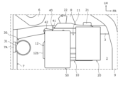
- 4 is a cross-sectional view taken along the line AA in FIG. 3 (a side view of the protective structure).
- FIG. 4 is a perspective view for explaining a fixing structure of the tray, showing the tray in a see-through state.
- 5A and 5B are side views of the protective structure according to the embodiment, in which FIG. 5A shows the protective structure in a normal state, and FIG. 5B shows the protective structure in a normal state and explains the protective structure's function during a frontal collision.
- the definition of directions is that the front-to-rear direction (vehicle length direction) is defined based on the forward and backward direction of the vehicle, and the left-to-right direction (vehicle width direction) is defined based on the front-to-rear direction.
- the up-to-down direction is defined based on the state in which the vehicle is stopped on a flat road surface. Note that in the vehicle width direction, in the part to the left of the vehicle body centerline in a top view of the vehicle, the left is the outside of the vehicle and the right is the inside of the vehicle. Also, in the part to the right of the vehicle body centerline in a top view of the vehicle, the right is the outside of the vehicle and the left is the inside of the vehicle.
- the vehicle protective structure of this embodiment is a structure that prevents damage to fuel system components due to interference between the tray and fuel system components placed in a storage compartment at the front of the vehicle during a vehicle frontal collision.
- the storage compartment referred to here includes, for example, an engine room, a motor room, a power unit room, etc., and is placed in front of the passenger compartment.
- fuel system components include a canister, a fuel filter, a fuel pump, and fuel piping.
- the tray is a tray-shaped member on which on-board equipment (e.g., a battery, an air cleaner, etc.) placed in the storage compartment is placed.
- FIG. 1 First, the structure of a vehicle 1 to which a protective structure as an embodiment is applied will be described. As shown in Fig. 1, various devices including an engine 51 and a transmission 52 are disposed in an accommodation compartment 2 at the front of the vehicle 1. An opening is provided at the upper end side of the accommodation compartment 2, and a bonnet hood (not shown) is attached to this opening so as to be able to be opened and closed.
- a bonnet hood (not shown) is attached to this opening so as to be able to be opened and closed.
- a pair of left and right side frames 3 extending in the front-to-rear direction are arranged below the storage compartment 2.
- the side frames 3 are skeletal members that support various devices inside the storage compartment 2 from below, and are installed at a specified distance in the vehicle width direction.
- the front ends of the left and right side frames 3 are connected to each other by an upper bar 9 (see Figure 2).
- the upper bar 9 is a member for supporting the front end of the bonnet hood, and is arranged, for example, along the edge of the opening to which the bonnet hood is attached.
- the upper frame 4 is connected to both the left and right ends of the upper bar 9.
- the upper frame 4 is one of the components that extends almost horizontally forward from near the lower end of the front pillar (not shown) of the vehicle 1.
- a pair of upper frames 4 are arranged on the left and right at the top of the accommodation compartment 2.
- the front fender panel 5 of the vehicle 1 is attached to the outside of the upper frame 4.
- the front wheels and spring house 6 are arranged below the upper frame 4.
- the upper bar 9 and upper frame 4 function to support the portion of the bonnet hood from both the left and right ends to the front end.
- a dash panel 7 that forms the rear surface of the storage compartment 2 is provided at the rear end of the storage compartment 2.
- the dash panel 7 is a planar member that divides the vehicle interior and the storage compartment 2 in the front-rear direction, and the space in front of the dash panel 7 forms the storage compartment 2.
- the dash panel 7 is erected to cover the rear end of the storage compartment 2, for example, from the upper end surface of the upper frame 4 to the upper end surface of the side frame 3.
- the lower end of the dash panel 7 is provided to extend rearward in a planar manner along, for example, the upper end surface of the side frame 3, and is connected to the floor panel (not shown) of the vehicle interior so as to be approximately flush with the vehicle interior floor panel.
- a fender shield 8 is attached inside the storage compartment 2.
- the fender shield 8 is a planar member that forms part of the bottom surface of the storage compartment 2 inside the fender panel 5 of the vehicle 1.
- the outer edge of the fender shield 8 on the vehicle side is connected to the upper frame 4.
- the inner edge of the fender shield 8 on the vehicle side may be connected to the side frame 3, or may be disposed so as to be spaced apart above the side frame 3.
- the power plant such as the engine 51 and transmission 52, is elastically attached to the side frame 3 via mounts.
- a mount 40 (see Figures 2 to 4) that supports the transmission 52 is exemplified.
- This mount 40 is an anti-vibration device for absorbing and damping vibrations of the transmission 52, and is fixed to the side frame 3.
- An elastic member such as anti-vibration rubber, liquid, or anti-vibration metal (not shown) is preferably enclosed inside the mount 40 to elastically support the transmission 52.
- the mount 40 has a cylindrical outer tube 41 and an inner tube (not shown) fitted inside the outer tube 41 via an elastic member.
- the axis of the outer tube 41 and the axis of the inner tube are approximately the same, and both are arranged in a direction extending in the vehicle width direction.
- the outer tube 41 is fastened and fixed to the upper surface of the side frame 3 via a mount fixing bracket 42.
- the mount fixing bracket 42 is a fixing device formed in the shape of a car stopper that fixes the position of the cylindrical outer tube 41.
- the range where the mount 40 is fixed (the fore-aft direction section, hereafter referred to as the "mount section M") has a higher rigidity on the vehicle body side than other positions.
- a battery 20 and an air cleaner 50 are arranged in the accommodation chamber 2 as on-board equipment.
- the battery 20 has a roughly rectangular parallelepiped outer shape, and is placed on and fixed to a tray 10 (described below) while, for example, placed on a tray (not shown).
- the air cleaner 50 is located immediately behind the battery 20, and is placed on and fixed to the tray 10.
- the fuel system component 30 attached to the dash panel 7 is located behind the air cleaner 50.
- the fuel system component 30 is a canister
- the external shape of the fuel system component 30 is roughly cylindrical, and a fixing bracket 31 (see Figures 2 to 4) is provided on its outer circumferential surface.
- the fuel system component 30 is attached to the dash panel 7 by inserting the fixing bracket 31 from above into a vehicle body bracket 7A fixed to the dash panel 7.
- the protective structure of this embodiment is a structure that protects the fuel system component 30 by preventing the tray 10 and the fuel system component 30 arranged in the accommodation chamber 2 from interfering with each other during a frontal collision of the vehicle 1.
- a protector separate component
- the shape of the tray 10 located in front of the fuel system component 30 is devised. Therefore, compared to the case where a protector is added, it is possible to avoid increases in weight and cost.
- the tray 10 is fixed to the side frame 3 in front of the fuel system components 30.
- the tray 10 is fixed to the side frame 3 at two locations, the front and rear, via support brackets 21 and 22.
- Figure 5 is an oblique view for explaining the fixing structure of the tray 10, with the outline of the tray 10 shown in bold and the components located below the tray 10 shown in solid lines when viewed through the tray 10.
- the front support bracket 21 (second support bracket) has one end 21a on the outer side (left side) in the vehicle width direction fixed to the side frame 3, and a support part 21b extending from the end 21a toward the inner side in the vehicle width direction is fixed to the underside of the front part of the tray 10. In this way, the front part of the tray 10 is fixed to the front support bracket 21 which is fixed to the side frame 3.
- the rear support bracket 22 (first support bracket) has one end 22a on the outer side (left side) in the vehicle width direction fixed to the fender shield 8, and a support portion 22b extending from the end 22a toward the inner side in the vehicle width direction is fixed to the underside of the rear of the tray 10.
- the support portion 22b of the rear support bracket 22 is placed on the mount 40, or is placed and fixed thereto, as shown by the dashed line in Figure 4, and connects the side frame 3 and the mount 40. In this way, the rear of the tray 10 is fixed to the rear support bracket 22 which connects the side frame 3 and the mount 40.
- the tray 10 of this embodiment has at least a mounting portion 11 on which the battery 20 is placed, and an inclined portion 12 provided at the rear end of the tray 10. These will be described in order below.
- the mounting portion 11 includes a battery mounting portion 11a on which the battery 20 is placed, and an air cleaner mounting portion 11b on which the air cleaner 50 is placed.
- the battery mounting portion 11a is a front area of the tray 10, and overlaps with the front support bracket 21 in the vertical direction.
- the air cleaner mounting portion 11b is a rear area of the battery mounting portion 11a, and overlaps with the rear support bracket 22 in the vertical direction. Note that, in this embodiment, a portion of the air cleaner mounting portion 11b on the outer side in the vehicle width direction is formed to bulge upward as shown in FIG. 4 in order to avoid contact with the mount 40 located below.
- the inclined portion 12 is a planar portion at the rear end of the tray 10 that slopes downward toward the rear.
- the rear end of the tray 10 faces the fuel system component 30.
- the inclined portion 12 is shaped like a slide, with its upper edge 12a positioned above the lower surface 30b of the fuel system component 30 and its lower edge 12b positioned below the lower surface 30b of the fuel system component 30.
- the lower surface 30b of the fuel system component 30 is positioned within the range of the height H of the inclined portion 12.
- the tray 10 of this embodiment is arranged so that the inclined portion 12 overlaps the mounting section M in a side view of the vehicle 1.
- “overlapping” means that at least a portion of the inclined portion 12 overlaps the mounting section M, and the entire inclined portion 12 does not necessarily have to be included in the mounting section M.
- the range indicated by the symbol S in FIG. 4 is the range in the front-to-rear direction of the inclined portion 12 (the front-to-rear dimension from the upper edge 12a to the lower edge 12b).
- the inclined portion 12 is formed by bending the rear edge of the mounting portion 11 (air cleaner mounting portion 11b) of the tray 10 obliquely downward.
- the upper edge 12a of the inclined portion 12 is also the rear edge of the mounting portion 11, and the lower edge 12b of the inclined portion 12 is also the rear edge of the tray 10.
- the inclined portion 12 of this embodiment is inclined downward at an inclination angle approximately equal to the rear inclination angle of the bulging portion of the air cleaner mounting portion 11b, forming an inclined surface that is approximately flush with the inclined surface of that portion.
- the part of the mounting portion 11 located just in front of the inclined portion 12 also has the same function as the inclined portion 12, improving the function of pushing up the fuel system component 30 during a frontal collision.
- the inclination angle of the inclined portion 12 relative to the upper surface of the tray 10 can be set as appropriate, and in the example shown in FIG. 4, it is approximately 40 to 45 degrees.
- the inclination angle of the inclined portion 12 may be set taking into consideration the positional relationship between the tray 10 and the fuel system component 30 (front-to-back distance, up-down position), the relationship with the devices and members arranged around the tray 10 and the fuel system component 30, and the respective rigidities of the tray 10 and the fuel system component 30, etc.
- the inclined portion 12 in this embodiment has a rear edge 12c on the outer side in the vehicle width direction that extends diagonally forward as it goes further outward in the vehicle width direction. This is to avoid contact with surrounding components located behind the outer side in the vehicle width direction of the tray 10, and is not essential.
- the vehicle width direction dimension of the rear end of the tray 10 may be approximately constant, or the left and right corners may be rounded like the front end of the tray 10.
- the inclined portion 12 in this embodiment has a vehicle width dimension W (see FIG. 3) that is larger than the vehicle width dimension of the fuel system component 30, and when viewed from the front (or top) of the vehicle 1, the fuel system component 30 is located within the vehicle width range of the inclined portion 12.
- W vehicle width dimension
- the inclined portion 12 comes into contact with the entire lower surface 30b of the fuel system component 30, improving the pushing-up function of the fuel system component 30 in the event of a frontal collision.
- the vehicle width direction dimension W' of the lower edge 12b of the inclined portion 12 will be shorter than the vehicle width direction dimension W of the upper edge 12a.
- the fuel system components 30 are located within the vehicle width direction range of the lower edge 12b of the inclined portion 12.
- the majority of the fuel system components 30 (approximately 80 to 90%) are located within the vehicle width direction range of the lower edge 12b of the inclined portion 12. In this way, it is preferable that the majority of the fuel system components 30 are located within the vehicle width direction range of the lower edge 12b of the inclined portion 12.
- the tray 10 of this embodiment has multiple beads 13 extending in the front-rear direction.
- the beads 13 have the function of increasing the rigidity of the tray 10, and are portions whose plate surfaces are formed in a concave or convex shape.
- two concave (i.e., downwardly convex) beads 13 are provided spaced apart on the left and right.
- the front end 13a of each bead 13 overlaps the front support bracket 21 in the vertical direction, and is located at the fixed portion between the tray 10 and the front support bracket 21.
- the rear end 13b of each bead 13 is located at the upper edge 12a of the inclined portion 12. In other words, the beads 13 extend in the front-rear direction from a position above the front support bracket 21 to the position of the inclined portion 12.
- the fuel system component 30 is attached to the dash panel 7, and the tray 10 is disposed in front of the fuel system component 30, and has an inclined portion 12 that slopes downward toward the rear at its rear end (the portion facing the fuel system component 30).
- the upper edge 12a of the inclined portion 12 is located above the lower surface 30b of the fuel system component 30, and the lower edge 12b of the inclined portion 12 is located below the lower surface 30b of the fuel system component 30.
- the inclined portion 12 can push up the fuel system component 30, preventing interference between the tray 10 and the fuel system component 30.
- the fuel system component 30 can be protected without providing additional components for protecting the fuel system component 30. Therefore, it is possible to ensure the protection performance of the fuel system component 30 during a frontal collision while avoiding increases in weight and cost.
- the inclined portion 12 is positioned to overlap the mount section M to which the mount 40 is fixed in a side view.
- the mount section M is a high-rigidity section that is unlikely to deform even when the vehicle 1 collides, and by positioning the inclined portion 12 so that it overlaps this section M, deformation of the inclined portion 12 can also be suppressed. This makes it possible to achieve the intended behavior of the inclined portion 12 of the tray 10 pushing up the fuel system component 30 during a frontal collision, thereby improving the protective performance of the fuel system component 30.
- the rear of the tray 10 is fixed to the rear support bracket 22 that connects the side frame 3 and the mount 40. This reduces the amount of deformation of the rear of the tray 10 during a frontal collision, making it possible to more accurately achieve the desired behavior. This further improves the protective performance of the fuel system components 30.
- the tray 10 has multiple beads 13 extending in the front-rear direction, which increases the rigidity of the tray 10.
- the tray 10 can stably support the on-board equipment (e.g., the battery 20) during normal times other than during a collision, and in the event of a frontal collision, deformation of the tray 10 itself can be suppressed, making it easier to achieve the desired behavior and improving the protective performance of the fuel system components 30.
- each bead 13 extends to the upper edge 12a of the inclined portion 12.
- the bead 13 can suppress deformation immediately in front of the inclined portion 12 during a frontal collision, and the inclined portion 12 can push up the fuel system component 30 as intended. Therefore, the protective performance of the fuel system component 30 can be improved.
- each bead 13 extends from a fixed portion with high rigidity, the rigidity of the tray 10 can be further improved.
- the inclined portion 12 has a vehicle width dimension W that is larger than the vehicle width dimension of the fuel system component 30, and the fuel system component 30 is located within the vehicle width range of the inclined portion 12 when viewed from the front or top of the vehicle 1.
- the inclined portion 12 is disposed over the entire front of the fuel system component 30. Therefore, when the tray 10 is retracted, the inclined portion 12 can abut against the entire lower surface 30b of the fuel system component 30, thereby enhancing the pushing-up effect of the fuel system component 30.
- the fuel system component 30 is attached by being inserted from above into the vehicle body side bracket 7A fixed to the dash panel 7. Therefore, the inclined portion 12 pushes up the fuel system component 30, so that the fuel system component 30 can be detached from the vehicle body side bracket 7A, and interference between the tray 10 and the fuel system component 30 can be further prevented. This further improves the protective performance of the fuel system component 30.
- the protective structure and the configuration of the vehicle 1 to which the protective structure is applied described above are merely examples, and are not limited to those described above.
- the number and arrangement of the beads 13 on the tray 10, and the positions of the front end 13a and the rear end 13b of the beads 13 are merely examples.
- a plurality of beads having different lengths in the front-rear direction may be arranged side by side in the left-right direction.
- the beads 13 may be omitted.
- the arrangement of the inclined portion 12 of the tray 10 is also one example and is not limited to the above.
- a portion of the inclined portion 12 may be arranged so as to overlap the mounting section M.
- the position of the inclined portion 12 may be set regardless of the mounting section M.
- the air cleaner 50 may be mounted in a different location and the air cleaner mounting portion 11b may be omitted from the tray 10.
- on-board equipment other than the air cleaner 50 may be placed on the air cleaner mounting portion 11b. Note that even if the battery 20 is placed, the battery 20 may be located behind the air cleaner 50 (or an alternative on-board equipment).
- the fuel system component 30 may be fixed to the vehicle body member using fasteners such as clips and bolts, adhesive, or the like.
- the body configuration of the vehicle 1 is not limited to that described above, and the method of fixing the tray 10 to the framework member is not limited to that described above.
- This technology can be used in the vehicle manufacturing industry where trays and fuel system components are placed inside a compartment at the front of the vehicle.
- Vehicle 2 Storage compartment 3 Side frame (framework member) 7 Dash panel (component) 7A Vehicle body side bracket 10 Tray 12 Inclined portion 12a Upper edge 12b Lower edge 13 Bead 13a Front end 13b Rear end 20 Battery (vehicle-mounted device) 21 Front support bracket (second support bracket) 22 Rear support bracket (first support bracket) 30 Fuel system part 30b Underside 40 Mount 51 Engine (power plant) 52 Transmission (power plant) M Mount section
Landscapes
- Engineering & Computer Science (AREA)
- Life Sciences & Earth Sciences (AREA)
- Sustainable Development (AREA)
- Sustainable Energy (AREA)
- Chemical & Material Sciences (AREA)
- Combustion & Propulsion (AREA)
- Transportation (AREA)
- Mechanical Engineering (AREA)
- Cooling, Air Intake And Gas Exhaust, And Fuel Tank Arrangements In Propulsion Units (AREA)
Priority Applications (2)
| Application Number | Priority Date | Filing Date | Title |
|---|---|---|---|
| JP2025509490A JPWO2024201887A1 (https=) | 2023-03-30 | 2023-03-30 | |
| PCT/JP2023/013149 WO2024201887A1 (ja) | 2023-03-30 | 2023-03-30 | 車両の保護構造 |
Applications Claiming Priority (1)
| Application Number | Priority Date | Filing Date | Title |
|---|---|---|---|
| PCT/JP2023/013149 WO2024201887A1 (ja) | 2023-03-30 | 2023-03-30 | 車両の保護構造 |
Publications (1)
| Publication Number | Publication Date |
|---|---|
| WO2024201887A1 true WO2024201887A1 (ja) | 2024-10-03 |
Family
ID=92904389
Family Applications (1)
| Application Number | Title | Priority Date | Filing Date |
|---|---|---|---|
| PCT/JP2023/013149 Ceased WO2024201887A1 (ja) | 2023-03-30 | 2023-03-30 | 車両の保護構造 |
Country Status (2)
| Country | Link |
|---|---|
| JP (1) | JPWO2024201887A1 (https=) |
| WO (1) | WO2024201887A1 (https=) |
Citations (5)
| Publication number | Priority date | Publication date | Assignee | Title |
|---|---|---|---|---|
| JPH06280710A (ja) * | 1993-03-29 | 1994-10-04 | Mazda Motor Corp | 燃料系部材の取付構造 |
| JP2006132362A (ja) * | 2004-11-04 | 2006-05-25 | Nissan Motor Co Ltd | 燃料フィルタの取り付け構造 |
| JP2012251525A (ja) * | 2011-06-07 | 2012-12-20 | Suzuki Motor Corp | 車両用エンジンの燃料供給装置 |
| JP2016168910A (ja) * | 2015-03-12 | 2016-09-23 | 三菱自動車工業株式会社 | バッテリー取付構造 |
| JP2019038412A (ja) * | 2017-08-25 | 2019-03-14 | トヨタ自動車株式会社 | 車載機器の保護構造 |
-
2023
- 2023-03-30 WO PCT/JP2023/013149 patent/WO2024201887A1/ja not_active Ceased
- 2023-03-30 JP JP2025509490A patent/JPWO2024201887A1/ja active Pending
Patent Citations (5)
| Publication number | Priority date | Publication date | Assignee | Title |
|---|---|---|---|---|
| JPH06280710A (ja) * | 1993-03-29 | 1994-10-04 | Mazda Motor Corp | 燃料系部材の取付構造 |
| JP2006132362A (ja) * | 2004-11-04 | 2006-05-25 | Nissan Motor Co Ltd | 燃料フィルタの取り付け構造 |
| JP2012251525A (ja) * | 2011-06-07 | 2012-12-20 | Suzuki Motor Corp | 車両用エンジンの燃料供給装置 |
| JP2016168910A (ja) * | 2015-03-12 | 2016-09-23 | 三菱自動車工業株式会社 | バッテリー取付構造 |
| JP2019038412A (ja) * | 2017-08-25 | 2019-03-14 | トヨタ自動車株式会社 | 車載機器の保護構造 |
Also Published As
| Publication number | Publication date |
|---|---|
| JPWO2024201887A1 (https=) | 2024-10-03 |
Similar Documents
| Publication | Publication Date | Title |
|---|---|---|
| US8777300B2 (en) | Shock absorber housing supporting apparatus for vehicle | |
| US10632827B2 (en) | Vehicle lower portion structure | |
| US9731766B2 (en) | Front vehicle body structure | |
| CN109131169B (zh) | 汽车电池安装结构 | |
| US20170028950A1 (en) | Front end module | |
| US9242676B2 (en) | Front vehicle body reinforcing structure | |
| US8365858B2 (en) | Harness arrangement structure of vehicle | |
| US8177259B2 (en) | Canister mounting structure | |
| JP5733153B2 (ja) | 車載機器の搭載構造 | |
| CN114644055A (zh) | 用于车辆的前围板结构 | |
| JP2008037135A (ja) | 車体後部のバッテリ搭載構造 | |
| JP2008254580A (ja) | 車両のリヤフレーム構造 | |
| JP5767842B2 (ja) | 車体前部構造 | |
| US11634182B2 (en) | Vehicle front structure | |
| WO2024201887A1 (ja) | 車両の保護構造 | |
| JP2011079471A (ja) | バッテリーの取付構造 | |
| KR20230096453A (ko) | 배터리 타격을 회피할 수 있는 서브프레임의 체결구조 | |
| JP5857655B2 (ja) | 車両のハーネス配設構造 | |
| CN109649499A (zh) | 前部车身的增强结构 | |
| JP5971132B2 (ja) | 車両用電装部品の支持装置 | |
| JP7601200B2 (ja) | 車載機器の固定構造 | |
| CN110203165B (zh) | 仪表板的构造 | |
| WO2024180622A1 (ja) | 車体構造 | |
| JP6107796B2 (ja) | 自動車の前部構造 | |
| JP6098618B2 (ja) | 自動車の前部構造 |
Legal Events
| Date | Code | Title | Description |
|---|---|---|---|
| 121 | Ep: the epo has been informed by wipo that ep was designated in this application |
Ref document number: 23930525 Country of ref document: EP Kind code of ref document: A1 |
|
| WWE | Wipo information: entry into national phase |
Ref document number: 2025509490 Country of ref document: JP |
|
| NENP | Non-entry into the national phase |
Ref country code: DE |
|
| 122 | Ep: pct application non-entry in european phase |
Ref document number: 23930525 Country of ref document: EP Kind code of ref document: A1 |