WO2024201874A1 - 車両構造 - Google Patents
車両構造 Download PDFInfo
- Publication number
- WO2024201874A1 WO2024201874A1 PCT/JP2023/013099 JP2023013099W WO2024201874A1 WO 2024201874 A1 WO2024201874 A1 WO 2024201874A1 JP 2023013099 W JP2023013099 W JP 2023013099W WO 2024201874 A1 WO2024201874 A1 WO 2024201874A1
- Authority
- WO
- WIPO (PCT)
- Prior art keywords
- vehicle
- reinforcement
- cross member
- floor panel
- surface portion
- Prior art date
- Legal status (The legal status is an assumption and is not a legal conclusion. Google has not performed a legal analysis and makes no representation as to the accuracy of the status listed.)
- Ceased
Links
Images



Classifications
-
- B—PERFORMING OPERATIONS; TRANSPORTING
- B62—LAND VEHICLES FOR TRAVELLING OTHERWISE THAN ON RAILS
- B62D—MOTOR VEHICLES; TRAILERS
- B62D33/00—Superstructures for load-carrying vehicles
- B62D33/02—Platforms; Open load compartments
Definitions
- the present invention relates to a vehicle structure.
- Patent Document 1 shows a truck bed floor structure in which a floor panel is laid on a floor frame having multiple cross members and a rear cross member erected between a pair of left and right side members extending in the fore-and-aft direction, and the floor is placed on a pair of left and right chassis frames extending in the fore-and-aft direction.
- the rear cross member at the very back and the cross member with the mounting bracket just before it are joined in the fore-and-aft direction by reinforcements and are fixed to the outriggers of the chassis frame, preventing deformation of the bed floor due to the forward inertial force when the vehicle is suddenly braked.
- the present invention aims to provide a vehicle structure with a highly durable cargo bed.
- the present invention comprises the following configurations.
- a floor panel that constitutes a central portion in a vehicle width direction at a bottom of a cargo bed of the vehicle; side panels connected to both ends of the floor panel in the vehicle width direction to define both ends of the bottom of the loading platform in the vehicle width direction;
- a reinforcement is joined to the floor panel and the side panel across a connection portion between the floor panel and the side panel, A cross member extending in the vehicle width direction along the bottom of the loading platform, and both ends of the cross member being joined to the floor panel, the side panel, and the reinforcement, respectively, across the connection portion; Equipped with Vehicle structure.
- the present invention provides a vehicle structure with a highly durable cargo bed.
- FIG. 1 is a side view of a vehicle to which the vehicle structure of the present invention is applied.
- FIG. 2 is a perspective view of the bottom of the loading platform as viewed from below.
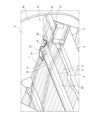
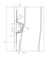
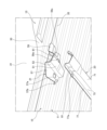
- FIG. 3 is a side view of the attachment points of the reinforcement and the cross member at the bottom of the cargo bed.
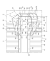
- FIG. 4 is a bottom view showing the attachment locations of the reinforcement and the cross member at the bottom of the cargo bed.
- FIG. 5 is a perspective view of the bottom of the cargo bed, showing the cargo bed, the reinforcement, and the cross member, as viewed from below.
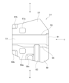
- FIG. 6A is a bottom view of the reinforcement.
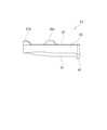
- FIG. 6B is a view taken along the arrow A in FIG. 6A.
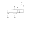
- FIG. 6C is a view taken along the arrow B in FIG. 6A.
- FIG. 6A is a bottom view of the reinforcement.
- FIG. 6B is a view taken along the arrow A in FIG. 6A.
- FIG. 6C is a view taken along the arrow B
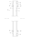
- FIG. 6D is a view taken along the arrow C in FIG. 6A.
- FIG. 7A is a bottom view of the cross member.
- FIG. 7B is a view taken along the arrow D in FIG. 7A.
- FIG. 7C is a view taken along the arrow E in FIG. 7A.
- FIG. 1 is a side view of a vehicle 100 to which the vehicle structure of the present invention is applied.
- vehicle structure according to this embodiment is applied to a vehicle 100, which is, for example, a small truck such as a pickup truck.
- vehicle 100 includes a cab 1 in which an occupant sits, and a cargo bed 3 provided behind the cab 1.
- vehicle 100 includes a chassis frame (frame) 5, and the cab 1 and the cargo bed 3 are supported by the chassis frame 5.
- Fig. 2 is a perspective view of the bottom 15 of the cargo bed 3 as viewed from below.
- Fig. 3 is a side view of the attachment locations of the bottom 15 of the cargo bed 3 to which the reinforcement 21 and the cross member 23 are attached.
- the chassis frame 5 is composed of side frames 7 and cross members 9.
- the chassis frame 5 has a pair of side frames 7 that extend in the front-rear direction of the vehicle with a gap in the vehicle width direction.
- the chassis frame 5 also has a plurality of cross members 9 that extend in the vehicle width direction at a plurality of locations that are spaced apart in the vehicle front-rear direction and are connected to the pair of side frames 7.
- the cargo bed 3 is positioned above the side frames 7.
- the cargo bed 3 includes a floor panel 11 and side panels 13.
- the floor panel 11 forms the center of the bottom 15 of the cargo bed 3 in the vehicle width direction.
- the side panels 13 are provided on both sides of the floor panel 11 in the vehicle width direction.
- the side panels 13 form both ends of the bottom 15 of the cargo bed 3 in the vehicle width direction and both sides of the cargo bed 3, and also form the wheel house 6 that houses the rear wheels (not shown) (see Figure 1).
- the cargo bed 3 is provided with reinforcing reinforcements 21 and cross members 23. These reinforcements 21 and cross members 23 are provided on the underside of the bottom 15 of the cargo bed 3, and are positioned above the side frames 7 that constitute the chassis frame 5 when viewed from the side of the vehicle.
- the side frames 7 are curved so as to bulge upward inside the wheel house 6. Moreover, because this reinforced location is the rear end of the wheel house 6 in the vehicle's fore-and-aft direction, the side panels 13 protrude outward in the vehicle width direction.
- the positions of both ends of the cross member 23 are positions where it is difficult to reinforce them by, for example, erecting a reinforcing plate on the side frame 7 and connecting both ends of the cross member 23 to this reinforcing plate. Therefore, it is desirable to effectively reinforce both ends of the cross member 23 with the reinforcements 21 and cross members 23.
- Figure 4 is a bottom view showing the attachment points of the reinforcement 21 and the cross member 23 on the bottom 15 of the cargo bed 3.
- Figure 5 is a perspective view of the bottom 15 of the cargo bed 3 from below, showing the cargo bed 3, the reinforcement 21, and the cross member 23.
- the floor panel 11 that constitutes the cargo bed 3 is a plate material with a corrugated cross section, and side panels 13 are connected to both ends of the floor panel 11 in the vehicle width direction.
- the side panel 13 has a bottom plate portion 31 and a side plate portion 33 that extends upward from the bottom plate portion 31, and the bottom plate portion 31 has a portion with a corrugated cross section like the floor panel 11.
- the ends of the bottom plate portion 31 of the side panel 13 are connected to the ends of the floor panel 11.
- the floor panel 11 and side panel 13 are joined by spot welding with the end of the bottom plate portion 31 of the side panel 13 overlapping the upper surface side of the end of the floor panel 11 (joint P1 in Figure 4).
- a connection portion 35 between the floor panel 11 and the side panel 13 is provided on the bottom 15 of the cargo bed 3 along the fore-and-aft direction of the vehicle.
- the two members, the floor panel 11 and the side panel 13 are spot welded (two-piece welding) with the two members overlapping.
- the end of the floor panel 11 may also be overlapped on the upper surface side of the end of the bottom plate portion 31 of the side panel 13 and joined by spot welding.
- the bottom 15 of the loading platform 3 is made up of a floor panel 11 with a corrugated cross section and a bottom plate portion 31 of a side panel 13.
- the bottom 15 of the loading platform 3 has a corrugated cross section with convex portions 41 and concave portions 43 formed alternately in the vehicle width direction.
- the connection portion 35 is a convex portion 41, and a concave portion 43 is provided on both sides of this connection portion 35. It is also possible that in the bottom 15 of the loading platform 3, the connection portion 35 is a concave portion 43, and a convex portion 41 is provided on both sides of this connection portion 35.
- the rigidity of the bottom 15 of the loading platform 3 is increased by the convex portions 41 and concave portions 43 that are alternately formed in the vehicle width direction.
- the convex portions 41 and concave portions 43 are formed along the vehicle front-rear direction, the bending strength of the bottom 15 of the loading platform 3 in the vehicle front-rear direction is increased.
- the bottom 15 of the cargo bed 3 configured as above has reinforcements 21 and cross members 23 provided in this order from the underside.
- the reinforcements 21 and cross members 23 are formed by pressing steel plates. These reinforcements 21 and cross members 23 are joined to the floor panel 11 and the side panel 13, respectively, in a state in which they are positioned across the connection portion 35 between the floor panel 11 and the side panel 13 at the bottom 15 of the cargo bed 3.
- FIG. 6A is a bottom view of the reinforcement 21.
- FIG. 6B is a view seen from the direction of arrow A in FIG. 6A.
- FIG. 6C is a view seen from the direction of arrow B in FIG. 6A.
- FIG. 6D is a view seen from the direction of arrow C in FIG. 6A.
- the reinforcement 21 has a first bottom surface portion 51, a first front side surface portion 53, a first rear side surface portion 55, a first front flange portion 57, and a first rear flange portion 59.
- the first front side portion 53 extends upward from the edge of the first bottom portion 51 on the front side in the vehicle fore-and-aft direction
- the first rear side portion 55 extends upward from the edge of the first bottom portion 51 on the rear side in the vehicle fore-and-aft direction
- the first front flange portion 57 extends forward in the vehicle fore-and-aft direction from the upper edge of the first front side portion 53
- the first rear flange portion 59 extends rearward in the vehicle fore-and-aft direction from the upper edge of the first rear side portion 55.
- the reinforcement 21 is applied to the bottom 15 of the cargo bed 3 from the first front flange portion 57 and the first rear flange portion 59, with the first front flange portion 57 facing forward in the vehicle's fore-and-aft direction and the first rear flange portion 59 facing rearward in the vehicle's fore-and-aft direction.
- the reinforcement 21 is then positioned across the connection portion 35 at the bottom 15 of the cargo bed 3 and joined to the floor panel 11 and the side panel 13.
- the reinforcement 21 has openings 57a, 59a in the first front flange portion 57 and the first rear flange portion 59, respectively. These openings 57a, 59a are formed in positions that overlap with the connection portion 35 when the reinforcement 21 is joined to the bottom portion 15 of the loading platform 3.
- the reinforcement 21 has a protrusion 57b on the first front flange portion 57, and protrusions 59b, 59c on the first rear flange portion 59.
- the protrusions 57b, 59b of the first front flange portion 57 and the first rear flange portion 59 are positioned at the position of the recess 43 on the floor panel 11 side adjacent to the connection portion 35 when the reinforcement 21 is joined to the bottom 15 of the cargo bed 3.
- the protrusion 59c of the first rear flange portion 59 is positioned at the position of the recess 43 on the side panel 13 side adjacent to the connection portion 35 when the reinforcement 21 is joined to the bottom 15 of the cargo bed 3.
- the reinforcement 21 also has a bulge 61 at the outer end in the vehicle width direction, where the concave portion consisting of the first bottom surface portion 51, the first front flange portion 57, and the first rear flange portion 59 is enlarged in diameter, and this bulge 61 increases the rigidity of the end of the reinforcement 21. More specifically, the bulge 61 is formed by the first bottom surface portion 51, the first rear side surface portion 55, and the first rear flange portion 59. Therefore, the bulge 63 increases the rigidity of the reinforcement 21 on the rear side in the vehicle front-rear direction.
- FIG. 7A is a bottom view of the cross member 23.
- FIG. 7B is a view seen from the arrow D in FIG. 7A.
- FIG. 7C is a view seen from the arrow E in FIG. 7A.
- the cross member 23 has a second bottom surface portion 71, a second front side surface portion 73, a second rear side surface portion 75, a second front flange portion 77, and a second rear flange portion 79.
- This cross member 23 has an elongated shape that extends in the vehicle width direction.
- the second front side portion 73 extends upward from the front edge of the second bottom portion 71 in the vehicle fore-and-aft direction
- the second rear side portion 75 extends upward from the rear edge of the second bottom portion 71 in the vehicle fore-and-aft direction
- the second front flange portion 77 extends forward in the vehicle fore-and-aft direction from the upper edge of the second front side portion 73
- the second rear flange portion 79 extends rearward in the vehicle fore-and-aft direction from the upper edge of the second rear side portion 75.
- the cross member 23 is positioned along the vehicle width direction with the second front flange portion 77 facing forward in the vehicle longitudinal direction and the second rear flange portion 79 facing rearward in the vehicle longitudinal direction relative to the bottom 15 of the cargo bed 3, and is joined to the floor panel 11 and the side panel 13 from the second front flange portion 77 and the second rear flange portion 79 sides. Both ends of the cross member 23 are joined to the bottom 15 of the cargo bed 3 via reinforcements 21.
- the cross member 23 also has overhangs 77a, 79a at the second front flange 77 and the second rear flange 79, which protrude by the thickness of the first front flange 57 and the first rear flange 59 of the reinforcement 21.
- These overhangs 77a, 79a are formed at positions corresponding to the openings 57a, 59a of the reinforcement 21.
- the cross member 23 has bulges 81 on the second front side surface portion 73 at both ends, which increase the rigidity of the cross member 23 on the front side in the vehicle's fore-and-aft direction.
- the cross member 23 has bulges 83 on the second rear side surface portion 75 and the second rear flange portion 79 at both ends, which extend along the vehicle's fore-and-aft direction, and these bulges 83 increase the rigidity of the cross member 23 on the rear side in the vehicle's fore-and-aft direction.
- the reinforcement 21 is placed on the attachment side to the bottom 15 at both ends of the cross member 23, and they are joined together by spot welding. Specifically, the overlapping area between the first bottom surface portion 51 of the reinforcement 21 and the second bottom surface portion 71 of the cross member 23 is spot welded. The overlapping area between the first front flange portion 57 of the reinforcement 21 and the second front flange portion 77 of the cross member 23 is also spot welded. The overlapping area between the first rear flange portion 59 of the reinforcement 21 and the second rear flange portion 79 of the cross member 23 is also spot welded (joint point P2 in FIG. 4).
- the reinforcement 21 is spot welded at the overlapping points between the first front flange portion 57 and the first rear flange portion 59 and the floor panel 11 and the side panel 13 (joint P3 in FIG. 4). At this joint P3, the two members, the reinforcement 21 and the floor panel 11 or the reinforcement 21 and the side panel 13, are spot welded (two-piece welding) in an overlapping state.
- the protrusions 57b, 59b of the first front flange portion 57 and the first rear flange portion 59 are positioned at the position of the recess 43 on the floor panel 11 side adjacent to the connection portion 35, and contact the bottom surface of the recess 43.
- the protrusion 59c of the first rear flange portion 59 is positioned at the position of the recess 43 on the side panel 13 side adjacent to the connection portion 35, and contact the bottom surface of the recess 43. Therefore, these protrusions 57b, 59b, 59c can be smoothly spot welded to the bottom 15 of the cargo bed 3.
- the overlapping areas of the first front flange portion 57 and the first rear flange portion 59 and the connection portion 35 are spot welded (joint P4 in FIG. 4).
- the three members of the reinforcement 21, the floor panel 11, and the side panel 13 are spot welded (three-piece welding) in an overlapping state.
- the cross member 23 is spot welded where the second front flange portion 77 and the second rear flange portion 79 overlap with the floor panel 11 (joint P5 in FIG. 4). At this joint P5, the cross member 23 and the floor panel 11 are spot welded (two-piece welding) while the two members are overlapped.
- the overlapping areas of the second front flange portion 77 and the second rear flange portion 79 and the connection portion 35 are spot welded (joint P6 in FIG. 4).
- the three members, the cross member 23, the floor panel 11, and the side panel 13, are spot welded (three-piece welding) in an overlapping state.
- the protruding portions 77a, 79a of the second front flange portion 77 and the second rear flange portion 79 contact the connection portion 35 through the openings 57a, 59a of the reinforcement 21. Therefore, the second front flange portion 77 and the second rear flange portion 79 can be smoothly spot welded to the connection portion 35 of the bottom 15 of the cargo bed 3.
- the cross member 23 is spot welded to the side panel 13 at the overlapping points between the second front flange portion 77 and the second rear flange portion 79 and the first front flange portion 57 and the first rear flange portion 59 of the reinforcement 21 (joint P7 in FIG. 4). At this joint P7, the three members of the cross member 23, the reinforcement 21, and the side panel 13 are spot welded (three-piece welding) in an overlapping state.
- connection parts 35 provided on the left and right sides of the bottom 15 of the cargo bed 3, these connection parts 35 can be effectively reinforced.
- the rigidity of the connection 35 between the floor panel 11 and the side panel 13 and the joints at both ends of the cross member 23, which are easily subjected to load, can be increased and strengthened by the reinforcement 21. This makes it possible to suppress damage and peeling off at both ends of the cross member 23 associated with twisting of the bottom 15 of the cargo bed 3, which occurs when driving on rough roads, etc. In particular, since it is possible to strengthen the areas around both ends of the cross member 23, which are subjected to load when the cargo bed 3 twists, peeling off of the connection 35 and both ends of the cross member 23 can be suppressed.
- the reinforcement 21 is made wider in the vehicle fore-and-aft direction than the cross member 23.
- the first front flange portion 57 and the first rear flange portion 59 of the reinforcement 21 protrude outward in the vehicle fore-and-aft direction from the second front flange portion 77 and the second rear flange portion 79 of the cross member 23.
- These protruding portions are then joined to the floor panel 11 and the side panel 13, respectively, at joint point P2. Therefore, the load caused by twisting of the bottom 15 of the cargo bed 3 can be received and distributed over a wide area in the vehicle fore-and-aft direction.
- connection 35 the three components of the side panel 13, floor panel 11, and reinforcement 21 are spot welded (three-piece welding) in an overlapping state at joint P4, and the three components of the side panel 13, floor panel 11, and cross member 23 are spot welded (three-piece welding) in an overlapping state at joint P6. This makes it possible to uniform the rigidity of the joints at the connection 35.
- both ends of the cross member 23 in the vehicle width direction and the entire reinforcement 21 can follow the deformation of the floor panel 11 and side panel 13, preventing damage or peeling caused by the concentration of load at specific points.
- both ends of the reinforcement 21 and cross member 23 joined to the bottom 15 of the cargo bed 3 are arranged such that the first bottom surface 51 and second bottom surface 71 are close to the top surface 7a of the side frame 7 constituting the chassis frame 5 and are positioned along the top surface 7a of the side frame 7.
- a sheet-like cushioning material (not shown) made of an elastic material such as rubber is provided in the gap between the top surface 7a of the side frame 7 and the second bottom surface 71 of the cross member 23. This allows the reinforcement 21 and cross member 23 to absorb the force transmitted from the side frame 7 to the bottom 15 of the cargo bed 3 when the vehicle is traveling.
- both ends of the reinforcement 21 and the cross member 23 have widened portions 25.
- the reinforcement 21 has a first rear side surface portion 55 that is inclined in a direction gradually moving away from the first front side surface portion 53 from the first bottom surface portion 51 toward the first rear flange portion 59
- the cross member 23 has a second rear side surface portion 75 that is inclined in a direction gradually moving away from the second front side surface portion 73 from the second bottom surface portion 71 toward the second rear flange portion 79.
- the angle between the first bottom surface portion 51 and the second bottom surface portion 71 and the first front side surface portion 53 and the second front side surface portion 73 is made larger than 90 degrees, and the angle between the first bottom surface portion 51 and the second bottom surface portion 71 and the first rear side surface portion 55 and the second rear side surface portion 75 is made larger than 90 degrees.
- the widening portion 25 extends inward from near the outer end in the vehicle width direction at the overlapping portion between the reinforcement 21 and both ends of the cross member 23.
- the left-right direction of this widening portion 25 is provided over the overlapping portion that overlaps with the side frame 7 in the vertical direction and the range W that extends from this overlapping portion to the connection portion 35.
- the connection portion 35 can be effectively reinforced.
- the angle ⁇ 1 of the rear side of the first front side portion 53 and the second front side portion 73 with respect to the upper surface 7a of the side frame 7 in the longitudinal direction of the vehicle and the angle ⁇ 2 of the front side of the first rear side portion 55 and the second rear side portion 75 with respect to the upper surface 7a of the side frame 7 in the longitudinal direction of the vehicle are set to 90 degrees or more (see FIG. 3). This makes it possible to suppress deformation and buckling due to the force applied to the reinforcement 21 and the cross member 23 from the side frame 7 when the vehicle is traveling. Note that these angles ⁇ 1 and ⁇ 2 are preferably 90 degrees.
- first rear side portion 55 and the second rear side portion 75 which have a larger vertical dimension than the first front side portion 53 and the second front side portion 73, to 90 degrees with respect to the upper surface 7a of the side frame 7, deformation and buckling due to the force applied from the side frame 7 can be effectively suppressed.
- the reinforcement 21 and cross member 23 are arranged and joined in order starting from the floor panel 11 and side panel 13 that constitute the bottom 15 of the cargo bed 3, but the cross member 23 and reinforcement 21 may also be arranged and joined in order starting from the floor panel 11 and side panel 13.
- an opening is formed in the cross member 23 at a position that overlaps with the connection portion 35, and the reinforcement 21 is joined to the floor panel 11 and side panel 13 at this opening. This makes it possible to uniformize the rigidity of the joint at the connection portion 35, and to avoid damage or peeling due to concentration of load at a specific location.
- the reinforcement 21 and the cross member 23 are joined to the bottom 15 of the loading platform 3 from the bottom side, but the reinforcement 21 and the cross member 23 may also be joined to the bottom 15 of the loading platform 3 from the top side.
- the present invention is not limited to the above-described embodiment, and the invention also contemplates the mutual combination of the various components of the embodiment, as well as modifications and applications by those skilled in the art based on the descriptions in the specification and well-known technology, and these are included in the scope of the protection sought.
- a floor panel that constitutes a central portion in a vehicle width direction at the bottom of a cargo bed of the vehicle; side panels connected to both ends of the floor panel in the vehicle width direction to define both ends of the bottom of the loading platform in the vehicle width direction;
- a reinforcement is joined to the floor panel and the side panel across a connection portion between the floor panel and the side panel, A cross member extending in the vehicle width direction along the bottom of the loading platform, and both ends of the cross member being joined to the floor panel, the side panel, and the reinforcement, respectively, across the connection portion;
- a vehicle structure comprising: According to this vehicle structure, the rigidity of the joints between the floor panel and the side panel and the joints at both ends of the cross member, which are easily subjected to load, can be increased and strengthened by the reinforcement.
- the reinforcement and the cross member are disposed in this order from the floor panel and the side panel side,
- the reinforcement has an opening at a position overlapping with the connection portion
- the vehicle structure according to claim 1 or 2 wherein the cross member is joined together with the floor panel and the side panel at the opening.
- an opening is provided at a position overlapping with the connection portion of the reinforcement, and the three members, the cross member, the floor panel, and the side panel, are joined at this opening. Therefore, it is possible to equalize the rigidity of the joints of the three members where the reinforcement is joined to the floor panel and the side panel at the connection portion. This allows both ends of the cross member and the entire reinforcement to conform to the deformation of the floor panel and side panel, preventing damage or peeling due to the concentration of load at specific points.
- the cross member and the reinforcement are disposed in this order from the floor panel and the side panel side,
- the cross member has an opening at a position overlapping with the connection portion
- an opening is provided at a position overlapping with the connection portion of the cross member, and the three members, the reinforcement, the floor panel, and the side panel, are joined at this opening. Therefore, it is possible to equalize the rigidity of the joints of the three members where the cross member is joined to the floor panel and the side panel at the connection portion. This allows both ends of the cross member and the entire reinforcement to conform to the deformation of the floor panel and side panel, preventing damage or peeling due to the concentration of load at specific points.
- the reinforcement is A first bottom portion; a first front side surface portion and a first rear side surface portion extending upward from both edges of the first bottom surface portion in the vehicle front-rear direction; a first front flange portion and a first rear flange portion extending in a front-rear direction of the vehicle along a bottom of the cargo bed from upper edges of the first front side surface portion and the first rear side surface portion, respectively; having
- the cross member is A second bottom portion; a second front side surface portion and a second rear side surface portion extending upward from both edges of the second bottom surface portion in the vehicle front-rear direction, a second front flange portion and a second rear flange portion extending in a front-rear direction of the vehicle along a bottom of the cargo bed from upper edges of the second front side surface portion and the second rear side surface portion, respectively;
- the vehicle structure according to (1) or (2) According to this vehicle structure, the cross-sectional shapes of the reinforcement and the cross member can be hat-shaped to increase rigidity, and the cargo bed of the
- the reinforcement and the cross member are disposed in this order from the floor panel and the side panel side,
- the reinforcement has an opening at a position overlapping with the connection portion in the first front flange portion and the first rear flange portion
- the vehicle structure according to claim 5 wherein the cross member has the second front flange portion and the second rear flange portion joined together with the floor panel and the side panel at the opening.
- openings are provided at positions overlapping with the connection portions of the first front flange portion and the first rear flange portion of the reinforcement, and the second front flange portion and the second rear flange portion of the cross member are joined to the floor panel and the side panel at the openings.
- the vehicle further includes a side frame that configures a frame of the vehicle, extends in a front-rear direction of the vehicle, and is arranged at a position overlapping both ends of the reinforcement and the cross member,
- the reinforcement and the cross member can absorb the force transmitted from the side frame to the bottom of the cargo bed when the vehicle is traveling.
- This vehicle structure makes it possible to suppress deformation and buckling caused by forces applied to the reinforcement and cross member from the side frames while the vehicle is traveling.
- the bottom of the loading platform has a corrugated cross-sectional shape in which convex portions and concave portions are alternately formed in the vehicle width direction
- the rigidity of the cargo bed can be increased by forming the bottom of the cargo bed into a corrugated cross-sectional shape in which convex and concave portions are alternately formed in the vehicle width direction.
- the connection portion in which both sides in the vehicle width direction are formed into convex or concave portions can be effectively reinforced by the reinforcement and the cross member.
Landscapes
- Engineering & Computer Science (AREA)
- Chemical & Material Sciences (AREA)
- Combustion & Propulsion (AREA)
- Transportation (AREA)
- Mechanical Engineering (AREA)
- Body Structure For Vehicles (AREA)
Priority Applications (2)
| Application Number | Priority Date | Filing Date | Title |
|---|---|---|---|
| PCT/JP2023/013099 WO2024201874A1 (ja) | 2023-03-30 | 2023-03-30 | 車両構造 |
| JP2025509480A JPWO2024201874A1 (cg-RX-API-DMAC7.html) | 2023-03-30 | 2023-03-30 |
Applications Claiming Priority (1)
| Application Number | Priority Date | Filing Date | Title |
|---|---|---|---|
| PCT/JP2023/013099 WO2024201874A1 (ja) | 2023-03-30 | 2023-03-30 | 車両構造 |
Publications (1)
| Publication Number | Publication Date |
|---|---|
| WO2024201874A1 true WO2024201874A1 (ja) | 2024-10-03 |
Family
ID=92903674
Family Applications (1)
| Application Number | Title | Priority Date | Filing Date |
|---|---|---|---|
| PCT/JP2023/013099 Ceased WO2024201874A1 (ja) | 2023-03-30 | 2023-03-30 | 車両構造 |
Country Status (2)
| Country | Link |
|---|---|
| JP (1) | JPWO2024201874A1 (cg-RX-API-DMAC7.html) |
| WO (1) | WO2024201874A1 (cg-RX-API-DMAC7.html) |
Citations (2)
| Publication number | Priority date | Publication date | Assignee | Title |
|---|---|---|---|---|
| JPH1095370A (ja) * | 1996-09-20 | 1998-04-14 | Hino Motors Ltd | 小型トラック用デッキの補強構造 |
| JP2019098827A (ja) * | 2017-11-29 | 2019-06-24 | トヨタ自動車株式会社 | 車両側部構造 |
Family Cites Families (4)
| Publication number | Priority date | Publication date | Assignee | Title |
|---|---|---|---|---|
| US5188418A (en) * | 1992-04-07 | 1993-02-23 | Pullman Industries, Inc. | Truck bed and method of manufacture |
| KR20050060745A (ko) * | 2003-12-17 | 2005-06-22 | 기아자동차주식회사 | 화물차량용 적재함 바닥 보강구조 |
| US7152911B1 (en) * | 2005-08-17 | 2006-12-26 | Pullman Industries, Inc. | Vehicle bed and cross rail attachment |
| US12662202B2 (en) * | 2021-03-30 | 2026-06-23 | Mitsubishi Jidosha Kogyo Kabushiki Kaisha | Vehicle body structure of cab-over type vehicle |
-
2023
- 2023-03-30 JP JP2025509480A patent/JPWO2024201874A1/ja active Pending
- 2023-03-30 WO PCT/JP2023/013099 patent/WO2024201874A1/ja not_active Ceased
Patent Citations (2)
| Publication number | Priority date | Publication date | Assignee | Title |
|---|---|---|---|---|
| JPH1095370A (ja) * | 1996-09-20 | 1998-04-14 | Hino Motors Ltd | 小型トラック用デッキの補強構造 |
| JP2019098827A (ja) * | 2017-11-29 | 2019-06-24 | トヨタ自動車株式会社 | 車両側部構造 |
Also Published As
| Publication number | Publication date |
|---|---|
| JPWO2024201874A1 (cg-RX-API-DMAC7.html) | 2024-10-03 |
Similar Documents
| Publication | Publication Date | Title |
|---|---|---|
| JP5316566B2 (ja) | 車両の上部構造 | |
| US7083225B2 (en) | Vehicle body structure of periphery of rear suspension | |
| US12409895B2 (en) | Lower vehicle-body structure | |
| CN112109811B (zh) | 车身结构和包括该车身结构的车辆 | |
| US7823958B2 (en) | Vehicle deck structure | |
| WO2016208374A1 (ja) | 車体前部構造 | |
| JP6647248B2 (ja) | 車体構造 | |
| JP6256518B2 (ja) | 車両の側部車体構造 | |
| JP4096940B2 (ja) | 車体後部構造 | |
| JP7135519B2 (ja) | ホイールハウス構造 | |
| JP4730779B2 (ja) | 自動車の車体後部構造 | |
| JP3465532B2 (ja) | クロスメンバ結合部構造 | |
| JP6579131B2 (ja) | 車両の前部車体構造 | |
| JP7397025B2 (ja) | 車両後部構造 | |
| JP7552327B2 (ja) | 車両側部の車体構造 | |
| JP4442987B2 (ja) | 自動車の車体側部構造 | |
| JP7223324B2 (ja) | 車体下部構造 | |
| JP3919054B2 (ja) | 自動車のサスペンションフレーム構造 | |
| JP2010228731A (ja) | 車両の床下構造 | |
| JP2000108947A (ja) | 車体フロア構造及び車体フロア構造の製造方法 | |
| JP2000211555A (ja) | 車両用シャシフレ―ム構造 | |
| KR101857030B1 (ko) | 테일게이트 개구부의 지지구조 | |
| JP2023010972A (ja) | 車両下部構造 | |
| JP7348601B1 (ja) | 車両の後部構造 | |
| JP4154918B2 (ja) | 自動車の後部車体構造 |
Legal Events
| Date | Code | Title | Description |
|---|---|---|---|
| 121 | Ep: the epo has been informed by wipo that ep was designated in this application |
Ref document number: 23930512 Country of ref document: EP Kind code of ref document: A1 |
|
| DPE1 | Request for preliminary examination filed after expiration of 19th month from priority date (pct application filed from 20040101) | ||
| WWE | Wipo information: entry into national phase |
Ref document number: 2025509480 Country of ref document: JP |
|
| NENP | Non-entry into the national phase |
Ref country code: DE |
|
| 122 | Ep: pct application non-entry in european phase |
Ref document number: 23930512 Country of ref document: EP Kind code of ref document: A1 |