WO2024201873A1 - 車両 - Google Patents
車両 Download PDFInfo
- Publication number
- WO2024201873A1 WO2024201873A1 PCT/JP2023/013098 JP2023013098W WO2024201873A1 WO 2024201873 A1 WO2024201873 A1 WO 2024201873A1 JP 2023013098 W JP2023013098 W JP 2023013098W WO 2024201873 A1 WO2024201873 A1 WO 2024201873A1
- Authority
- WO
- WIPO (PCT)
- Prior art keywords
- bracket
- vehicle
- console
- width direction
- receiving portion
- Prior art date
- Legal status (The legal status is an assumption and is not a legal conclusion. Google has not performed a legal analysis and makes no representation as to the accuracy of the status listed.)
- Ceased
Links
Images



Classifications
-
- B—PERFORMING OPERATIONS; TRANSPORTING
- B60—VEHICLES IN GENERAL
- B60K—ARRANGEMENT OR MOUNTING OF PROPULSION UNITS OR OF TRANSMISSIONS IN VEHICLES; ARRANGEMENT OR MOUNTING OF PLURAL DIVERSE PRIME-MOVERS IN VEHICLES; AUXILIARY DRIVES FOR VEHICLES; INSTRUMENTATION OR DASHBOARDS FOR VEHICLES; ARRANGEMENTS IN CONNECTION WITH COOLING, AIR INTAKE, GAS EXHAUST OR FUEL SUPPLY OF PROPULSION UNITS IN VEHICLES
- B60K1/00—Arrangement or mounting of electrical propulsion units
-
- B—PERFORMING OPERATIONS; TRANSPORTING
- B60—VEHICLES IN GENERAL
- B60R—VEHICLES, VEHICLE FITTINGS, OR VEHICLE PARTS, NOT OTHERWISE PROVIDED FOR
- B60R7/00—Stowing or holding appliances inside vehicle primarily intended for personal property smaller than suit-cases, e.g. travelling articles, or maps
- B60R7/04—Stowing or holding appliances inside vehicle primarily intended for personal property smaller than suit-cases, e.g. travelling articles, or maps in driver or passenger space, e.g. using racks
-
- B—PERFORMING OPERATIONS; TRANSPORTING
- B62—LAND VEHICLES FOR TRAVELLING OTHERWISE THAN ON RAILS
- B62D—MOTOR VEHICLES; TRAILERS
- B62D25/00—Superstructure or monocoque structure sub-units; Parts or details thereof not otherwise provided for
- B62D25/20—Floors or bottom sub-units
Definitions
- the present invention relates to a vehicle in which on-board equipment is arranged in the center console.
- Patent Document 1 discloses a configuration in which, in a vehicle in which electrical components housed inside the center console are attached to the vehicle assembly section via a bracket, the bracket used to attach the electrical components to the vehicle assembly section is used to integrally connect the vehicle assembly section and the center console.
- Patent Document 1 aims to reinforce the center console while ensuring installation space for electrical components within the center console.
- the liquid leaking from the box may get onto the electrical components arranged in the center console, leading to failure of the electrical components.
- the present invention was made in consideration of such circumstances, and aims to provide a vehicle that can prevent liquid that spills into a box provided in the center console from leaking onto on-board equipment placed in the center console.
- a vehicle in which an on-board device is disposed inside a center console in a front-rear direction that is disposed between a pair of seats that are arranged side by side in a vehicle width direction The center console is a console bracket provided to cover an upper side of the in-vehicle device disposed on an upper surface side of a floor and fixed to the floor; a box attached to an upper side of the console bracket via a fixing hole formed in the console bracket; a receiving portion provided between the fixing hole and the in-vehicle device; Equipped with The receiving portion is disposed at a position overlapping with the fixing hole in the front-rear direction and the vehicle width direction of the vehicle. vehicle.
- the console bracket has a first bracket including a first upper surface portion extending in a vehicle width direction and having the fixing hole formed therein, and a pair of first leg portions extending in a vertical direction from both ends of the first upper surface portion in the vehicle width direction toward the floor, The vehicle described in [1].
- the console bracket has a second bracket including: a second upper surface portion extending in a vehicle width direction, the second upper surface portion having the receiving portion formed thereon and extending in the vehicle width direction from one end in a front-rear direction toward the fixing hole; and a pair of second leg portions extending in a vertical direction from both ends of the second upper surface portion in the vehicle width direction toward the floor.
- the first bracket and the second bracket are connected to the receiving portion and the first upper surface portion, respectively.
- the second bracket further has a first locking piece extending in the front-rear direction from one end in the front-rear direction toward the first bracket, The first upper surface portion of the first bracket and the second bracket is sandwiched between the first locking piece from above and the receiving portion from below.
- the second bracket further has a second locking piece extending in the front-rear direction from one end in the front-rear direction toward the first bracket, the receiving portion is disposed on one side of the second upper surface portion in a vehicle width direction, the second locking piece is disposed on the other side of the second upper surface portion in a vehicle width direction, and the first locking piece is disposed between the receiving portion and the second locking piece in the vehicle width direction,
- the first bracket and the second bracket have the first upper surface portion sandwiched between the first locking piece from above and the receiving portion and the second locking piece from below, and the receiving portion and the first upper surface portion are connected to each other, and the second locking piece and the first upper surface portion are connected to each other, The vehicle described in [5].
- the pair of first leg portions each extend outward in a vehicle width direction and further include a first fixing portion fixed to the floor
- the pair of second leg portions each extend inward in a vehicle width direction and further include a second fixing portion fixed to the floor.
- the receiving portion has a groove portion extending in the front-rear direction or the vehicle width direction from an overlapping position where the receiving portion overlaps with the fixing hole to a retracted position where the receiving portion does not overlap with the vehicle-mounted device.
- a duct is provided that extends in the front-rear direction along the upper surface of the floor and is covered by the console bracket, The duct is disposed so as to overlap with the retracted position in a plan view in the vertical direction.
- the second bracket further has a duct support piece extending from the other end in the front-rear direction toward the opposite side in the front-rear direction to the first bracket and supporting the duct by suspending it. The vehicle described in [9].
- This invention can prevent liquid that has spilled into a box in the center console from leaking onto on-board equipment placed in the center console.
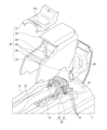
- FIG. 1 is a perspective view showing a center console.
- FIG. 2 is an exploded perspective view showing the center console.
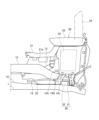
- FIG. 3 is a side view of a main portion showing the inside of the rear console unit.
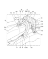
- FIG. 4 is a front perspective view showing a manner in which the console bracket is attached.
- FIG. 5 is a rear view showing the manner in which the console bracket is attached.
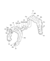
- 6A and 6B are a perspective view and a bottom view of the console bracket.
- FIG. 7 is an exploded perspective view of the console bracket.
- the direction of travel of the vehicle is referred to as "front”, and the rear of the vehicle is referred to as "rear”.
- the left side of the vehicle in the direction of travel is referred to as “left”, and the right side of the vehicle in the direction of travel is referred to as “right”.
- the left-right direction and the vehicle width direction are synonymous, and the front-rear direction and the vehicle direction are synonymous.
- FIG. 1 is a perspective view showing a center console
- Fig. 2 is an exploded perspective view showing the center console
- Fig. 3 is a side view of the main part showing the inside of the rear console unit
- Fig. 4 and Fig. 5 are a front perspective view and a rear view showing the mounting manner of the console bracket.
- a vehicle such as a passenger car is provided with a driver's seat 2 arranged on the front right side of a floor 1, a passenger seat 3 arranged on the front left side of the floor 1, and front and rear center consoles 10 arranged between the driver's seat 2 and the passenger seat 3.
- a central protrusion 1A is formed in the floor 1 in the front-rear direction between the driver's seat 2 and the passenger seat 3.
- the center console 10 is provided on the central protrusion 1A of the floor 1.
- the driver's seat 2 and the passenger seat 3 may be reversed left and right.
- the center console 10 has a console front portion 11 , an air conditioner duct 12 , a cooler box duct 13 , a brake harness 14 , a rear console unit 20 , and a console bracket 30 .
- the center console 10 extends in the fore-and-aft direction, and has its front portion covered by a console front portion 11 and its rear portion covered by a rear console unit 20.
- An air conditioner duct 12, a cooler box duct 13, and a brake harness 14 are disposed in the fore-and-aft direction along a central protrusion 1A of the floor 1, and are covered by the console front portion 11 and the rear console unit 20.
- the console bracket 30 covers, in particular, the rear side and top surfaces of the air conditioner duct 12 and the brake harness 14, and supports the rear console unit 20 on its top surface. This configuration can be seen in Figures 2 and 3.
- the rear console unit 20 has a cup holder 21, an armrest 22, a cooler box 23, a rear panel 24, a side panel 25, and a support frame 26.
- the cup holder 21 and the cooler box 23 are arranged in a row in the front-to-rear direction from the front.
- the armrest 22 covers the top side of the cooler box 23 in an openable and closable manner.
- the rear panel 24 covers the rear side of the cooler box 23.
- a pair of side panels 25, 25 extending forward from the cooler box 23 are attached to the left and right sides of the cooler box 23.
- the support frame 26 is provided in front of the cooler box 23 so as to bridge between the pair of side panels 25, 25. This configuration can be seen in FIG. 2.
- the cup holder 21 is a plate-like member with a recessed storage section 21a that can store containers such as plastic bottles.
- the cup holder 21 is removably attached so that it is placed on the upper edge sides of the pair of side panels 25, 25 and the support frame 26.
- the armrest 22 is a plate-like member that covers the opening of the cooler box 23, and the upper surface side is covered with a cushioned member.
- the rear end side of the armrest 22 is supported on the rear end side of the opening of the cooler box via a left-right support shaft. This allows the opening of the cooler box 23 to be opened and closed by swinging the front end side of the armrest 22 up and down. See Figure 3 for this configuration.
- the cooler box 23 is formed in a box shape with an open top so that containers such as plastic bottles can be stored therein.
- a pair of left and right recesses 23a and fixing holes 23b drilled in the bottom surface of the recesses 23a are formed in the bottom surface of the cooler box 23.
- a bottom plate 27 that covers the recesses 23a and the fixing holes 23b is fitted into the bottom surface of the cooler box 23. This configuration can be seen in FIG. 5.
- the upper surface of the connection portion between the front surface of the cooler box 23 and the cooler box duct 13 is covered by the cup holder 21, and the left and right sides are covered by side panels 25, 25.
- the rear panel 24 has an air outlet (not shown) formed on the upper side.
- the rear panel 24 is provided with a vertical connecting duct 28 that connects the air outlet to the rear end of the air conditioner duct 12. This configuration can be seen in Figure 2.
- the air conditioner duct 12 and the cold storage box duct 13 extend in the front-rear direction along the inside of the center console 10.
- the front ends of the air conditioner duct 12 and the cold storage box duct 13 are connected to the engine room side, and cold air cooled by a condenser arranged in the engine room (not shown) is supplied to them.
- the rear end side of the air conditioning duct 12 is connected to a connecting duct 28. This allows the air conditioning duct 12 to supply cool air from the air outlet of the rear panel 24 toward a rear seat (not shown) behind the driver's seat 2 and the passenger seat 3.
- the rear end side of the cold storage box duct 13 is connected to the front part of the cold storage box 23. This allows the cold storage box duct 13 to supply cool air into the cold storage box 23 in the rear console unit 20.
- the rear portion of the air conditioner duct 12 is suspended and supported by a console bracket 30 via a duct support piece 12A that protrudes from the upper surface side.
- a duct support piece 12A that protrudes from the upper surface side.
- the brake harness 14 extends in the front-rear direction along the inside of the center console 10.
- the front end of the brake harness 14 is connected to a control unit (not shown).
- the middle part of the brake harness 14 in the front-rear direction is supported on the console bracket 30 side.
- the brake harness 14 is divided into a right rear wheel brake harness 14R that extends toward the right rear wheel behind the console bracket 30, and a left rear wheel brake harness 14L.
- the rear end of the brake harness 14 is connected to an actuator (not shown) for applying electric brakes to the rear wheels.
- the manner in which the brake harness 14 is attached to the console bracket 30 will be described later.
- FIGS. 6(A) and 6(B) are a perspective view and a bottom view of the console bracket, and Figure 7 is an exploded perspective view of the console bracket.
- the console bracket 30 has a first bracket 31 and a second bracket 32 arranged in front of and adjacent to the first bracket 31 .
- the first bracket 31 and the second bracket 32 are each formed in an inverted U-shape, with their lower ends fixed by bolts to the central protrusion 1A of the floor 1.
- an air conditioner duct 12 is disposed at the center, and a brake harness 14 is disposed on one of the left and right sides. This configuration can be seen in Figures 2 to 5.
- the first bracket 31 has a pair of left and right first legs 31a, 31a extending in the up-down direction, and a first upper surface portion 31b extending in the left-right direction so as to connect the upper ends of the pair of left and right first legs 31a, 31a.
- the pair of first legs 31a are formed in a hat shape by being slightly inclined outward in the left and right direction as they extend downward.
- the pair of first legs 31a, 31a are formed with first fixing parts 33, 33 for fixing to the floor 1 side by bending the lower ends of the pair of first legs 31a, 31a outward in the left and right direction.
- a plurality of harness fixing holes 34 for attaching and fixing the brake harness 14 are provided vertically on the left or right inner surface of the first leg 31a on one of the left and right sides. In the illustrated example, four harness fixing holes 34 are provided vertically on the left first leg 31a.
- the harness fixing holes 34 arranged vertically are used to attach and fix the upper and lower parts of the harness 14R for the right rear wheel brake and the harness 14L for the left rear wheel brake, via the harness fixing devices 15. This configuration can be seen in Figures 3 to 5.
- a pair of left and right fixing holes 40L, 40R are formed in the rear side of the first upper surface portion 31b, penetrating in the up-down direction.
- the bottom side of the cooler box 23 is fixed to the upper surface of the first upper surface portion 31b of the first bracket 31 with bolts through the fixing holes 40L, 40R.
- a fixing bolt 50 is inserted through fixing hole 23b of cool storage box 23 and fixing holes 40L, 40R of first upper surface portion 31b, and then fastened to a fixing nut disposed on the underside of first upper surface portion 31b, thereby fixing the underside of cool storage box 23 to the upper surface of first bracket 31.
- the head of fixing bolt 50 is received in recess 23a of cool storage box 23 and is covered by bottom plate 27. This configuration may be seen in FIG. 5.
- the second bracket 32 has a pair of left and right second leg portions 32a, 32a extending in the up-down direction, and a second upper surface portion 32b extending in the left-right direction so as to connect the upper ends of the pair of left and right second leg portions 32a, 32a.
- the pair of second legs 32 a, 32 a have their lower sides curved forward.
- the pair of second legs 32 a, 32 a have their lower ends curved inward in the left-right direction to form second fixing portions 35, 35 for fixing the pair of second legs 32 a, 32 a to the floor 1.
- a harness support piece 39 that protrudes forward is formed on the lower side of the pair of second leg portions 32a, 32a.
- a harness fixing hole 39a for supporting the brake harness 14 is formed in the harness support piece 39.
- the second upper surface portion 32b is formed with a duct support piece 36, a locking piece 37, and a receiving piece 38.
- the duct support piece 36 is disposed on the front edge of the second upper surface portion 32b.
- the locking piece 37 and the receiving piece 38 are disposed on the rear edge of the second upper surface portion 32b.
- the duct support piece 36 has an extension portion 36a extending downward and forward from the front edge of the second upper surface portion 32b, an abutment portion 36b provided at the front end of the extension portion 36a and abutting against the duct support piece 12A, and a duct support hole 36c formed in the abutment portion 36b in the left-right direction.
- the extension portion 36a is located to the right of the left-right center of the second upper surface portion 32b, and the extension end side is bent to the left.
- the locking piece 37 has a first locking piece 37A and a second locking piece 37B which extend rearward from the rear edge of the second upper surface portion 32b.
- the first locking piece 37A is positioned in the left-right center of the second upper surface portion 32b and is bent upward in a crank shape so as to abut against the upper surface of the first upper surface portion 31b of the first bracket 31.
- the second locking piece 37B is positioned on the right side of the second upper surface portion 32b in the left-right direction and is bent downward in a crank shape so as to abut against the underside of the first upper surface portion 31b of the first bracket 31.
- first locking piece 37A and the second locking piece 37B are arranged side by side on the left and right, and are provided so as to sandwich the first upper surface portion 31b of the first bracket 31 from above and below.
- the second locking piece 37B and the first upper surface portion 31b are joined by spot welding. This allows the first bracket 31 and the second bracket 32, which are arranged side by side in front of the first bracket 31, to be integrally connected. Note that the first locking piece 37A and the first upper surface portion 31b are not spot welded.
- the receiving piece 38 has an extension portion 38a, a receiving portion 38b, and a guide portion 38c.
- the extension portion 38a extends rearward from the left side in the left-right direction of the rear edge portion of the second upper surface portion 32b.
- the receiving portion 38b is formed on the rear end side of the extension portion 38a, and is a dish-shaped portion recessed downward, with a portion of the circumferential direction open and connected to the guide portion 38c.
- the receiving portion 38b is disposed so as to overlap with the fixing hole 40L on one of the left and right sides of the first upper surface portion 31b in a plan view. In the illustrated example, the receiving portion 38b overlaps with the fixing hole 40L on the left side.
- the receiving portion 38b is provided so as to cover the entire fixing hole 40L in a plan view.
- the guide portion 38c is a groove portion that extends inward in the left-right direction from the receiving portion 38b with the central portion recessed downward. In the illustrated example, the guide portion 38c extends rightward, continuing from the right portion of the receiving portion 38b.
- the base end side of the guide portion 38c is connected to the dish-shaped receiving portion 38b.
- the free end side of the guide portion 38c extends to a predetermined retracted position that overlaps with the upper surface of the air conditioner duct 12 in a rear view or a plan view. This configuration can be seen in FIG. 5.
- the receiving piece 38 abuts against the underside of the first upper surface portion 31b at some position and is joined by spot welding.
- the receiving piece 38 may be joined to the first upper surface portion 31b by providing a protrusion extending in the front-rear direction on the extension portion 38a, or a protrusion provided on the free end side of the guide portion 38c may be joined to the first upper surface portion 31b.
- FIG. 7 For this configuration, refer to FIG. 7.
- the liquid guided to the predetermined retracted position by guide portion 38c is guided to fall onto the upper surface of air conditioner duct 12.
- the liquid that has leaked onto the upper surface of air conditioner duct 12 flows down along the side surface of air conditioner duct 12.
- the right fixing hole 40R is disposed so as to overlap with the upper surface of the air-conditioning duct 12 in a plan view. Therefore, liquid dropping from the fixing hole 40R of the first bracket 31 drips directly onto the upper surface of the air-conditioning duct 12. According to the above, any liquid that spills into the cooler box 23 and drips from the fixing holes 23b, 40L, 40R flows down the air conditioner duct 12 and falls onto the floor 1. This makes it possible to more reliably prevent liquid that falls with force from the cooler box 23 from splashing on the floor 1 and coming into contact with electrical components such as the brake harness 14.
- the console bracket 30 described above is configured by arranging the first bracket 31 and the second bracket 32, which are separate bodies, in front and behind each other, so that each component can have a simple shape, thereby making it possible to keep manufacturing costs low.
- the installation work of the console bracket 30 on the floor 1 side is also simplified.
- by dividing the console bracket 30 into the first bracket 31 and the second bracket 32 it is possible to use brackets formed of materials with different plate thicknesses at the front and rear. That is, by making the plate thickness of the first bracket 31 to which the cooler box is attached thicker than the plate thickness of the second bracket 32, it is possible to ensure rigidity and reduce manufacturing costs in the entire console bracket 30.
- the plate thickness of the first bracket 31 is 1.6 cm
- the plate thickness of the second bracket 32 is 1.2 cm.
- the console bracket 30 can ensure a wide front-to-rear distance between the first leg 31a and the second leg 32a by bending the lower portions of the second legs 32a, 32a of the second bracket 32 forward, which makes the position of the console bracket 30 fixed to the floor 1 more stable.
- the first fixing portions 33, 33 of the first bracket 31 and the second fixing portions 35, 35 of the second bracket 32 are offset in the left-right direction when viewed from the bottom. This makes the position of the console bracket 30 fixed to the floor 1 more stable.
- the present invention is not limited to the above-described embodiment, and can be modified or improved as appropriate.
- the present specification discloses the following: (1) In a vehicle in which an on-board device is disposed inside a center console in a front-rear direction that is disposed between a pair of seats that are arranged side by side in a vehicle width direction,
- the center console is a console bracket provided to cover an upper side of the in-vehicle device disposed on an upper surface side of a floor and fixed to the floor; a box attached to an upper side of the console bracket via a fixing hole formed in the console bracket; a receiving portion provided between the fixing hole and the in-vehicle device; Equipped with The receiving portion is disposed at a position overlapping with the fixing hole in the front-rear direction and the vehicle width direction of the vehicle. vehicle. According to this configuration, any liquid spilled into the box can be received by the receiving portion, thereby preventing the liquid from leaking onto the in-vehicle equipment.
- the console bracket has a first bracket including a first upper surface portion extending in a vehicle width direction and in which the fixing hole is formed, and a pair of first legs extending in a vertical direction from both ends of the first upper surface portion in the vehicle width direction toward the floor.
- a vehicle as described in (1) According to this configuration, the box can be fixed to the upper surface side of the first bracket which is bent into an inverted U-shape, so that the box can be stably supported.
- the console bracket has a second bracket including: a second upper surface portion extending in a vehicle width direction, the second upper surface portion having the receiving portion formed thereon and extending in the vehicle width direction from one end in a front-rear direction toward the fixing hole; and a pair of second leg portions extending in a vertical direction from both ends of the second upper surface portion in the vehicle width direction toward the floor.
- the console bracket is divided into the first bracket in which the fixing hole is formed and the second bracket in which the receiving portion is formed, so that the shape of each bracket is simplified and costs can be kept low.
- the first bracket that supports the box can be supported by the second bracket, so that the box can be supported more stably.
- the first bracket and the second bracket are connected to the receiving portion and the first upper surface portion, respectively.
- the second bracket further includes a first locking piece extending in the front-rear direction from one end in the front-rear direction toward the first bracket, The first upper surface portion of the first bracket and the second bracket is sandwiched between the first locking piece from above and the receiving portion from below.
- the second bracket further includes a second locking piece extending in the front-rear direction from one end in the front-rear direction toward the first bracket, the receiving portion is disposed on one side of the second upper surface portion in a vehicle width direction, the second locking piece is disposed on the other side of the second upper surface portion in a vehicle width direction, and the first locking piece is disposed between the receiving portion and the second locking piece in the vehicle width direction,
- the first bracket and the second bracket have the first upper surface portion sandwiched between the first locking piece from above and the receiving portion and the second locking piece from below, and the receiving portion and the first upper surface portion are connected to each other, and the second locking piece and the first upper surface portion are connected to each other, (5) A vehicle as described in (5). According to this configuration, the first bracket and the second bracket can be firmly fixed to each other.
- the pair of first leg portions each extend outward in a vehicle width direction and further include a first fixing portion fixed to the floor
- the pair of second leg portions each extend inward in a vehicle width direction and further include a second fixing portion fixed to the floor.
- the receiving portion has a groove portion extending in the front-rear direction and the vehicle width direction from an overlapping position where the receiving portion overlaps with the fixing hole to a retracted position where the receiving portion does not overlap with the vehicle-mounted device.
- a duct is provided that extends in the front-rear direction along the upper surface of the floor and is covered by the console bracket, The duct is disposed so as to overlap with the retracted position in a plan view in the vertical direction.
- the second bracket further includes a duct support piece extending from another end in the front-rear direction toward a side opposite to the first bracket in the front-rear direction and supporting the duct by suspending it.
- a vehicle as described in (1) According to this configuration, the duct can be supported by the second bracket that constitutes the console bracket.
Landscapes
- Engineering & Computer Science (AREA)
- Mechanical Engineering (AREA)
- Chemical & Material Sciences (AREA)
- Combustion & Propulsion (AREA)
- Transportation (AREA)
- Vehicle Step Arrangements And Article Storage (AREA)
Abstract
車幅方向に並べて配置された一対の座席の間に配置され、前後方向に延在するセンターコンソールと、センターコンソールの上部に配置される車載機器と、車載機器の上側を覆うように設けられ、センターコンソールに取付けられるコンソールブラケットと、コンソールブラケットに形成された固定孔を介して、コンソールブラケットの上側に取付けられるボックスと、固定孔と、車載機器と、の間に設けられた受部と、を備え、固定孔は、車両の前後方向及び車幅方向で車載機器と重複する位置に配置され、受部は、固定孔の真下側に配置される。
Description
本発明は、センターコンソール内に車載機器が配置された車両に関する。
近年、乗用自動車等の車両の高機能化にともなって、車両における電装部品の搭載数が増加している一方で、車両内で電装部品が設置可能なスペースは限られている。そのため、乗員によって直接操作されない車載機器の一部を、センターコンソールの内部のデッドスペース内に配置した車両が従来から知られている。
特許文献1では、センターコンソールの内部に収容された電装部品が、ブラケットを介して車両組付部に組付けられる車両において、電装部品の車両組付部への組付けに用いるブラケットを利用して、車両組付部とセンターコンソールとを一体的に連結した構成が開示されている。
上記特許文献1では、センターコンソール内における電装部品の設置スペースを確保しつつ、センターコンソールの補強を図ったものである。しかし、センターコンソールに設けたボックスに収容されたペットボトル等から液体がこぼれた場合に、ボックスから漏下した液体が、センターコンソール内に配置した電装部品にかかって、電装部品の故障につながり得るという課題がある。
本発明は、このような状況に鑑みてなされたものであり、センターコンソールに設けたボックス内にこぼれた液体が、センターコンソール内に配置した車載機器に漏下することを防止できる車両を提供することを目的とする。
本発明の上記目的は、下記の構成により達成される。
[1] 車幅方向に並べて配置された一対の座席の間に配置される前後方向のセンターコンソールの内部に車載機器が配置される車両において、
前記センターコンソールは、
フロアの上面側に配置される前記車載機器の上側を覆うように設けられ、前記フロアに固定されるコンソールブラケットと、
前記コンソールブラケットに形成された固定孔を介して、前記コンソールブラケットの上側に取付けられるボックスと、
前記固定孔と前記車載機器との間に設けられる受部と、
を備え、
前記受部は、車両の前後方向及び車幅方向で前記固定孔と重複する位置に配置される、
車両。
[2] 前記コンソールブラケットは、車幅方向に延在し、前記固定孔が形成された第1上面部と、前記第1上面部の車幅方向両端側から前記フロアに向けて上下方向に延在する一対の第1脚部と、を備えた第1ブラケットを有する、
[1]に記載の車両。
[3] 前記コンソールブラケットは、車幅方向に延在し、前後方向一端部から前記固定孔に向けて前後方向に延在する前記受部が形成された第2上面部と、前記第2上面部の車幅方向両端側から前記フロアに向けて上下方向に延在する一対の第2脚部と、を備えた第2ブラケットを有する、
[2]に記載の車両。
[4] 前記第1ブラケットと前記第2ブラケットとは、前記受部と前記第1上面部とがそれぞれ接続されている、
[3]に記載の車両。
[5] 前記第2ブラケットは、前後方向一端部から前記第1ブラケットに向けて前後方向に延在する第1係止片をさらに有し、
前記第1ブラケットと前記第2ブラケットとは、上側から前記第1係止片、下側から前記受部によって前記第1上面部が挟み込まれている、
[4]に記載の車両。
[6] 前記第2ブラケットは、前後方向一端部から前記第1ブラケットに向けて前後方向に延在する第2係止片をさらに有し、
前記第2上面部の車幅方向一方側に前記受部、車幅方向他方側に前記第2係止片、車幅方向における前記受部と前記第2係止片との間に前記第1係止片が配置され、
前記第1ブラケットと前記第2ブラケットとは、上側から前記第1係止片、下側から前記受部および前記第2係止片によって前記第1上面部が挟み込まれるとともに、前記受部と前記第1上面部および前記第2係止片と前記第1上面部とがそれぞれ接続されている、
[5]に記載の車両。
[7] 前記一対の第1脚部は、それぞれ車幅方向外側に延在し、前記フロアに固定される第1固定部をさらに有し、
前記一対の第2脚部は、車幅方向内側にそれぞれ延在し、前記フロアに固定される第2固定部をさらに有する、
[3]~[6]の何れか1つに記載の車両。
[8] 前記受部は、前後方向及び車幅方向で、前記固定孔と重なる重複位置から前記車載機器と重ならない退避位置まで前後方向又は車幅方向に延在する溝部を有する、
[3]~[6]の何れか1つに記載の車両。
[9] 前記フロアの上面に沿って前後方向に延在し、前記コンソールブラケットによって覆われるダクトを設け、
前記ダクトは、上下方向において、平面視で前記退避位置と重なるように配置される、
[8]に記載の車両。
[10] 前記第2ブラケットは、前後方向他端部から前記第1ブラケットと前後方向逆側に向けて延在し、前記ダクトを吊り下げ支持するダクト支持片をさらに有する、
[9]に記載の車両。
[1] 車幅方向に並べて配置された一対の座席の間に配置される前後方向のセンターコンソールの内部に車載機器が配置される車両において、
前記センターコンソールは、
フロアの上面側に配置される前記車載機器の上側を覆うように設けられ、前記フロアに固定されるコンソールブラケットと、
前記コンソールブラケットに形成された固定孔を介して、前記コンソールブラケットの上側に取付けられるボックスと、
前記固定孔と前記車載機器との間に設けられる受部と、
を備え、
前記受部は、車両の前後方向及び車幅方向で前記固定孔と重複する位置に配置される、
車両。
[2] 前記コンソールブラケットは、車幅方向に延在し、前記固定孔が形成された第1上面部と、前記第1上面部の車幅方向両端側から前記フロアに向けて上下方向に延在する一対の第1脚部と、を備えた第1ブラケットを有する、
[1]に記載の車両。
[3] 前記コンソールブラケットは、車幅方向に延在し、前後方向一端部から前記固定孔に向けて前後方向に延在する前記受部が形成された第2上面部と、前記第2上面部の車幅方向両端側から前記フロアに向けて上下方向に延在する一対の第2脚部と、を備えた第2ブラケットを有する、
[2]に記載の車両。
[4] 前記第1ブラケットと前記第2ブラケットとは、前記受部と前記第1上面部とがそれぞれ接続されている、
[3]に記載の車両。
[5] 前記第2ブラケットは、前後方向一端部から前記第1ブラケットに向けて前後方向に延在する第1係止片をさらに有し、
前記第1ブラケットと前記第2ブラケットとは、上側から前記第1係止片、下側から前記受部によって前記第1上面部が挟み込まれている、
[4]に記載の車両。
[6] 前記第2ブラケットは、前後方向一端部から前記第1ブラケットに向けて前後方向に延在する第2係止片をさらに有し、
前記第2上面部の車幅方向一方側に前記受部、車幅方向他方側に前記第2係止片、車幅方向における前記受部と前記第2係止片との間に前記第1係止片が配置され、
前記第1ブラケットと前記第2ブラケットとは、上側から前記第1係止片、下側から前記受部および前記第2係止片によって前記第1上面部が挟み込まれるとともに、前記受部と前記第1上面部および前記第2係止片と前記第1上面部とがそれぞれ接続されている、
[5]に記載の車両。
[7] 前記一対の第1脚部は、それぞれ車幅方向外側に延在し、前記フロアに固定される第1固定部をさらに有し、
前記一対の第2脚部は、車幅方向内側にそれぞれ延在し、前記フロアに固定される第2固定部をさらに有する、
[3]~[6]の何れか1つに記載の車両。
[8] 前記受部は、前後方向及び車幅方向で、前記固定孔と重なる重複位置から前記車載機器と重ならない退避位置まで前後方向又は車幅方向に延在する溝部を有する、
[3]~[6]の何れか1つに記載の車両。
[9] 前記フロアの上面に沿って前後方向に延在し、前記コンソールブラケットによって覆われるダクトを設け、
前記ダクトは、上下方向において、平面視で前記退避位置と重なるように配置される、
[8]に記載の車両。
[10] 前記第2ブラケットは、前後方向他端部から前記第1ブラケットと前後方向逆側に向けて延在し、前記ダクトを吊り下げ支持するダクト支持片をさらに有する、
[9]に記載の車両。
本発明によれば、センターコンソールに設けたボックス内にこぼれた液体が、センターコンソール内に配置した車載機器に液漏下することを防止できる。
以下、本発明の一実施形態に係る車両について、図面を参照して説明する。また、本実施形態は本発明の一例を示したものであって、本発明は本実施形態に限定されるものではない。また、本実施形態には種々の変更又は改良を加えることが可能であり、その様な変更又は改良を加えた形態も本発明に含まれ得る。
本実施例において、車両の進行方向を「前」、車両の後進後方を「後」と称する。車両の進行方向左側を「左」、車両の進行方向右側を「右」と称する。また、左右方向と、車幅方向とは同義であり、前後方向と、車両方向とは同義である。
(全体構成)
図1は、センターコンソールを示した斜視図であり、図2は、センターコンソールを示した分解斜視図であり、図3は、リヤコンソールユニットの内部を示した要部側面図であり、図4及び図5は、コンソールブラケットの取付態様を示した前面斜視部と、背面図である。乗用自動車等からなる車両には、フロア1の前部右側に配置された運転席2と、フロア1の前部左側に配置された助手席3と、運転席2及び助手席3の間に配置された前後のセンターコンソール10と、が設けられている。フロア1には、運転席2及び助手席3の間に設けられた前後方向の中央突部1Aが形成されている。センターコンソール10はフロア1の中央突部1A上に設けられている。なお、運転席2及び助手席3は左右反対であってもよい。
図1は、センターコンソールを示した斜視図であり、図2は、センターコンソールを示した分解斜視図であり、図3は、リヤコンソールユニットの内部を示した要部側面図であり、図4及び図5は、コンソールブラケットの取付態様を示した前面斜視部と、背面図である。乗用自動車等からなる車両には、フロア1の前部右側に配置された運転席2と、フロア1の前部左側に配置された助手席3と、運転席2及び助手席3の間に配置された前後のセンターコンソール10と、が設けられている。フロア1には、運転席2及び助手席3の間に設けられた前後方向の中央突部1Aが形成されている。センターコンソール10はフロア1の中央突部1A上に設けられている。なお、運転席2及び助手席3は左右反対であってもよい。
センターコンソール10は、コンソールフロント部11と、エアコン用ダクト12と、保冷ボックス用ダクト13と、ブレーキ用ハーネス14と、リヤコンソールユニット20と、コンソールブラケット30と、を有する。
前後方向に延在するセンターコンソール10は、その前部がコンソールフロント部11でカバーされ、その後部がリヤコンソールユニット20でカバーされている。エアコン用ダクト12と、保冷ボックス用ダクト13と、ブレーキ用ハーネス14と、はフロア1の中央突部1Aに沿って前後方向に配設され、コンソールフロント部11及びリヤコンソールユニット20によって覆われている。コンソールブラケット30は、特に、エアコン用ダクト12及びブレーキ用ハーネス14の後部側の側面及び上面をカバーするとともに、上面側にリヤコンソールユニット20が支持されている。この構成は、図2及び図3を参照するとよい。
前後方向に延在するセンターコンソール10は、その前部がコンソールフロント部11でカバーされ、その後部がリヤコンソールユニット20でカバーされている。エアコン用ダクト12と、保冷ボックス用ダクト13と、ブレーキ用ハーネス14と、はフロア1の中央突部1Aに沿って前後方向に配設され、コンソールフロント部11及びリヤコンソールユニット20によって覆われている。コンソールブラケット30は、特に、エアコン用ダクト12及びブレーキ用ハーネス14の後部側の側面及び上面をカバーするとともに、上面側にリヤコンソールユニット20が支持されている。この構成は、図2及び図3を参照するとよい。
リヤコンソールユニット20は、カップホルダ21と、アームレスト22と、保冷ボックス23と、リヤパネル24と、サイドパネル25と、支持フレーム26と、を有する。
カップホルダ21及び保冷ボックス23は、前から順に前後方向に並べて配置される。アームレスト22は、保冷ボックス23の上面側を開閉可能にカバーする。リヤパネル24は、保冷ボックス23の後面側をカバーする。保冷ボックス23の左右両側には、保冷ボックス23より前方に延在する一対のサイドパネル25、25が取付けられる。支持フレーム26は、保冷ボックス23の前方で一対のサイドパネル25、25の間を架け渡すように設けられている。この構成は、図2を参照するとよい。
カップホルダ21及び保冷ボックス23は、前から順に前後方向に並べて配置される。アームレスト22は、保冷ボックス23の上面側を開閉可能にカバーする。リヤパネル24は、保冷ボックス23の後面側をカバーする。保冷ボックス23の左右両側には、保冷ボックス23より前方に延在する一対のサイドパネル25、25が取付けられる。支持フレーム26は、保冷ボックス23の前方で一対のサイドパネル25、25の間を架け渡すように設けられている。この構成は、図2を参照するとよい。
カップホルダ21は、ペットボトル等の容器が収容可能に凹設された収容部21aが形成された板状部材である。カップホルダ21は、一対のサイドパネル25、25の上縁側と、支持フレーム26と、に載置されるようにして、着脱可能に取付けられる。
アームレスト22は、保冷ボックス23の開口部を覆う板状部材であって、上面側がクッション性のある部材によって覆われている。アームレスト22の後端側は、保冷ボックスの開口部後端側に左右方向の支持軸を介して軸支されている。これにより、アームレスト22は、前端側を上下方向に揺動操作することで、保冷ボックス23の開口部を開閉できる。この構成は、図3を参照するとよい。
保冷ボックス23は、ペットボトル等の容器が収容できるように上方が開放された箱状に形成されている。保冷ボックス23の底面には、左右一対の凹部23aと、凹部23aの底面に穿設された固定孔23bと、が形成されている。また、保冷ボックス23の底面には、凹部23a及び固定孔23bを覆う底板27が嵌め込まれている。この構成は、図5を参照するとよい。
なお、保冷ボックス23の前面と保冷ボックス用ダクト13との接続箇所は、その上面がカップホルダ21で覆われ、その左右側方は、サイドパネル25、25によって覆われている。
なお、保冷ボックス23の前面と保冷ボックス用ダクト13との接続箇所は、その上面がカップホルダ21で覆われ、その左右側方は、サイドパネル25、25によって覆われている。
リヤパネル24は、上部側に不図示の送風口が形成されている。リヤパネル24には、送風口と、エアコン用ダクト12の後端と、を接続する上下方向の連結ダクト28が設けられている。この構成は、図2を参照するとよい。
エアコン用ダクト12及び保冷ボックス用ダクト13は、センターコンソール10内に沿って前後方向に延在する。エアコン用ダクト12及び保冷ボックス用ダクト13の前端側は、エンジンルーム側に接続され、不図示のエンジンルーム内に配置されたコンデンサによって冷却された冷風が供給される。
エアコン用ダクト12の後端側は、連結ダクト28に接続されている。これにより、エアコン用ダクト12は、リヤパネル24の送風口から、運転席2及び助手席3の後方の不図示の後部座席に向けて冷風を供給できる。
保冷ボックス用ダクト13の後端側は、保冷ボックス23の前部に接続されている。これにより、保冷ボックス用ダクト13は、リヤコンソールユニット20内の保冷ボックス23内に冷風を供給できる。
エアコン用ダクト12の後端側は、連結ダクト28に接続されている。これにより、エアコン用ダクト12は、リヤパネル24の送風口から、運転席2及び助手席3の後方の不図示の後部座席に向けて冷風を供給できる。
保冷ボックス用ダクト13の後端側は、保冷ボックス23の前部に接続されている。これにより、保冷ボックス用ダクト13は、リヤコンソールユニット20内の保冷ボックス23内に冷風を供給できる。
なお、エアコン用ダクト12の後部は、上面側に突設されるダクト支持片12Aを介して、コンソールブラケット30に吊り下げ支持されている。
これにより、前後方向において、後述するガイド部38cの最下部に沿った断面において、エアコン用ダクト12の上面は一番高い位置にある右後輪ブレーキ用ハーネス14Rよりもさらに高い位置にある。この構成は、図5を参照するとよい。
これにより、前後方向において、後述するガイド部38cの最下部に沿った断面において、エアコン用ダクト12の上面は一番高い位置にある右後輪ブレーキ用ハーネス14Rよりもさらに高い位置にある。この構成は、図5を参照するとよい。
ブレーキ用ハーネス14は、センターコンソール10内に沿って前後方向に延在する。ブレーキ用ハーネス14の前端側は、不図示の制御部に接続される。ブレーキ用ハーネス14の前後方向中途部は、コンソールブラケット30側に支持される。ブレーキ用ハーネス14は、コンソールブラケット30より後方側で、右側の後輪に向けて延設される右後輪ブレーキ用ハーネス14Rと、左後輪ブレーキ用ハーネス14Lと、に分けられる。ブレーキ用ハーネス14の後端側は、後輪に電動ブレーキを作用させるための不図示のアクチュエータに接続される。ブレーキ用ハーネス14のコンソールブラケット30への取付態様については後述する。
次に、図2~図7に基づき、コンソールブラケットの具体的な構成について説明する。図6(A)及び図6(B)は、コンソールブラケットの斜視図及び底面図であり、図7は、コンソールブラケットの分解斜視図である。
コンソールブラケット30は、第1ブラケット31と、第1ブラケット31の前側に並べて配置される第2ブラケット32と、を有する。
第1ブラケット31及び第2ブラケット32は、それぞれ逆U字状に形成され、その下端側がフロア1の中央突部1A側にボルト固定されている。また、第1ブラケット31及び第2ブラケット32と、中央突部1Aと、の間に形成される前後方向のスペースには、その中央側にエアコン用ダクト12が配置され、その左右一方側には、ブレーキ用ハーネス14が配置される。この構成は、図2~図5を参照するとよい。
第1ブラケット31及び第2ブラケット32は、それぞれ逆U字状に形成され、その下端側がフロア1の中央突部1A側にボルト固定されている。また、第1ブラケット31及び第2ブラケット32と、中央突部1Aと、の間に形成される前後方向のスペースには、その中央側にエアコン用ダクト12が配置され、その左右一方側には、ブレーキ用ハーネス14が配置される。この構成は、図2~図5を参照するとよい。
第1ブラケット31は、上下方向に延在する左右一対の第1脚部31a、31aと、左右一対の第1脚部31a、31aの上端側同士を連結するように左右方向に延在する第1上面部31bと、を有する。
一対の第1脚部31aは、下方に向かうにつれて左右外側に若干傾斜することにより、ハット型に形成される。一対の第1脚部31a、31aには、下端側を左右方向外側に向けて屈曲形成することにより、フロア1側に固定するための第1固定部33、33が形成される。
第1脚部31aの左右一方側には、左右内面側にブレーキ用ハーネス14を取付固定するためのハーネス固定孔34が上下方向に並べて複数設けられている。図示する例では、左側の第1脚部31aに、4つのハーネス固定孔34が上下方向に並べて設けられている。
第1脚部31aの左右一方側には、左右内面側にブレーキ用ハーネス14を取付固定するためのハーネス固定孔34が上下方向に並べて複数設けられている。図示する例では、左側の第1脚部31aに、4つのハーネス固定孔34が上下方向に並べて設けられている。
上下に並べて配置されたハーネス固定孔34には、ハーネス固定具15を介して、上下に分割された右後輪ブレーキ用ハーネス14Rと、左後輪ブレーキ用ハーネス14Lと、がそれぞれ取付固定されている。この構成は、図3~図5を参照するとよい。
第1上面部31bは、その後部側に上下方向に貫通する左右一対の固定孔40L、40Rが形成されている。固定孔40L、40Rを介して、第1ブラケット31の第1上面部31bの上面に、保冷ボックス23の底面側がボルト固定される。
具体的に説明すると、保冷ボックス23の固定孔23bと、第1上面部31bの固定孔40L、40Rと、に挿通した固定ボルト50を、第1上面部31bの下面に配置した固定ナットに締結することにより、保冷ボックス23の下面を第1ブラケット31の上面に固定できる。このとき、固定ボルト50の頭部は、保冷ボックス23の凹部23aに収容され、底板27によって覆われる。この構成は、図5を参照するとよい。
具体的に説明すると、保冷ボックス23の固定孔23bと、第1上面部31bの固定孔40L、40Rと、に挿通した固定ボルト50を、第1上面部31bの下面に配置した固定ナットに締結することにより、保冷ボックス23の下面を第1ブラケット31の上面に固定できる。このとき、固定ボルト50の頭部は、保冷ボックス23の凹部23aに収容され、底板27によって覆われる。この構成は、図5を参照するとよい。
第2ブラケット32は、上下方向に延在する左右一対の第2脚部32a、32aと、左右一対の第2脚部32a、32aの上端側同士を連結するように左右方向に延在する第2上面部32bと、を有する。
一対の第2脚部32a、32aは、下部側が前方に向けて湾曲する。一対の第2脚部32a、32aには、その下端側を左右方向内側に向けて屈曲形成することにより、フロア1側に固定するための第2固定部35、35が形成される。
一対の第2脚部32a、32aの下部側には、前方に向けて突出されたハーネス支持片39が形成されている。ハーネス支持片39には、ブレーキ用ハーネス14を支持するためのハーネス固定孔39aが形成されている。
一対の第2脚部32a、32aの下部側には、前方に向けて突出されたハーネス支持片39が形成されている。ハーネス支持片39には、ブレーキ用ハーネス14を支持するためのハーネス固定孔39aが形成されている。
第2上面部32bには、ダクト支持片36と、係止片37と、受け片38と、が形成される。ダクト支持片36は、第2上面部32bの前縁部に配置される。係止片37及び受け片38は、第2上面部32bの後縁部に配置される。
ダクト支持片36は、第2上面部32bの前縁部から前方下側に向けて延在する延設部36aと、延設部36aの前端に設けられて、ダクト支持片12Aと当接する当接部36bと、当接部36bに形成された左右方向のダクト支持孔36cと、を有する。なお、延設部36aは、第2上面部32bの左右方向中央の右寄りに配置され、延設端側が左方向に屈曲形成されている。
これにより、ダクト支持片36の当接部36bと、当接部36bに当接させたダクト支持片12Aと、を取付固定することにより、コンソールブラケット30に、エアコン用ダクト12の後部を吊り下げ支持できる。この構成は、図4及び図6を参照するとよい。
これにより、ダクト支持片36の当接部36bと、当接部36bに当接させたダクト支持片12Aと、を取付固定することにより、コンソールブラケット30に、エアコン用ダクト12の後部を吊り下げ支持できる。この構成は、図4及び図6を参照するとよい。
係止片37は、第2上面部32bの後縁部から後方に向けて延在する、第1係止片37A及び第2係止片37Bを有する。
第1係止片37Aは、第2上面部32bの左右方向中央に配置され、上側に向けてクランク状に屈曲形成されることにより、第1ブラケット31の第1上面部31bの上面に当接するように設けられる。
第2係止片37Bは、第2上面部32bの左右方向の右側に配置され、下側に向けてクランク状に屈曲形成されることにより、第1ブラケット31の第1上面部31bの下面に当接するように設けられる。
すなわち、第1係止片37A及び第2係止片37Bは、左右に並べて配置され、第1ブラケット31の第1上面部31bを上下で挟むように設けられている。このとき、第2係止片37Bと第1上面部31bとは、スポット溶接によって接合される。これにより、第1ブラケット31と、第1ブラケット31の前方に並べて配置される第2ブラケット32とを、一体的に連結できる。なお、第1係止片37Aと第1上面部31bとは、スポット溶接されていない。
第1係止片37Aは、第2上面部32bの左右方向中央に配置され、上側に向けてクランク状に屈曲形成されることにより、第1ブラケット31の第1上面部31bの上面に当接するように設けられる。
第2係止片37Bは、第2上面部32bの左右方向の右側に配置され、下側に向けてクランク状に屈曲形成されることにより、第1ブラケット31の第1上面部31bの下面に当接するように設けられる。
すなわち、第1係止片37A及び第2係止片37Bは、左右に並べて配置され、第1ブラケット31の第1上面部31bを上下で挟むように設けられている。このとき、第2係止片37Bと第1上面部31bとは、スポット溶接によって接合される。これにより、第1ブラケット31と、第1ブラケット31の前方に並べて配置される第2ブラケット32とを、一体的に連結できる。なお、第1係止片37Aと第1上面部31bとは、スポット溶接されていない。
受け片38は、延設部38aと、受部38bと、ガイド部38cと、を有する。
延設部38aは、第2上面部32bの後縁部の左右方向の左側から後方に向けて延在する。
受部38bは、延設部38aの後端側に形成され、下方に窪んだ皿状部分であって、周方向の一部を開放してガイド部38cと繋がっている。また、受部38bは、平面視で第1上面部31bの左右一方側の固定孔40Lと重なるように配置される。図示する例では、受部38bは、左側の固定孔40Lと重なっている。このとき、受部38bは、平面視で固定孔40Lの全体をカバーするように設けられる。この構成は、図5、図6(A)及び図6(B)を参照するとよい。
ガイド部38cは、中央部分を下方に凹ませて受部38bから左右方向の内側に延在する溝部である。図示する例では、ガイド部38cは、受部38bの右側部分から連続して、右側に延在する。ガイド部38cの基端側は、皿状の受部38bに連接される。ガイド部38cの自由端側は、背面視又は平面視でエアコン用ダクト12の上面と重なる所定の退避位置まで延設されている。この構成は、図5を参照するとよい。
延設部38aは、第2上面部32bの後縁部の左右方向の左側から後方に向けて延在する。
受部38bは、延設部38aの後端側に形成され、下方に窪んだ皿状部分であって、周方向の一部を開放してガイド部38cと繋がっている。また、受部38bは、平面視で第1上面部31bの左右一方側の固定孔40Lと重なるように配置される。図示する例では、受部38bは、左側の固定孔40Lと重なっている。このとき、受部38bは、平面視で固定孔40Lの全体をカバーするように設けられる。この構成は、図5、図6(A)及び図6(B)を参照するとよい。
ガイド部38cは、中央部分を下方に凹ませて受部38bから左右方向の内側に延在する溝部である。図示する例では、ガイド部38cは、受部38bの右側部分から連続して、右側に延在する。ガイド部38cの基端側は、皿状の受部38bに連接される。ガイド部38cの自由端側は、背面視又は平面視でエアコン用ダクト12の上面と重なる所定の退避位置まで延設されている。この構成は、図5を参照するとよい。
また、受け片38は、何れかの位置で第1上面部31bの下面と当接し、スポット溶接によって接合されている。受け片38は、延設部38aに前後方向に延在する凸部を設けて第1上面部31bと接合してもよいし、ガイド部38cの自由端側に設けた凸部を第1上面部31bに接合してもよい。この構成は、図7を参照するとよい。
(作用効果)
上述のコンソールブラケット30によれば、保冷ボックス23内に液体がこぼれた際、保冷ボックス23の固定孔40Lから漏下した液体を、受部38bで受け止め、ガイド部38cによって左右方向内側に案内できる。
これにより、保冷ボックス23内にこぼれた液体が、保冷ボックス23の固定孔23bと、第1ブラケット31の固定孔40Lと、を介して、電装部品であるブレーキ用ハーネス14に漏下することを確実に防止できる。
上述のコンソールブラケット30によれば、保冷ボックス23内に液体がこぼれた際、保冷ボックス23の固定孔40Lから漏下した液体を、受部38bで受け止め、ガイド部38cによって左右方向内側に案内できる。
これにより、保冷ボックス23内にこぼれた液体が、保冷ボックス23の固定孔23bと、第1ブラケット31の固定孔40Lと、を介して、電装部品であるブレーキ用ハーネス14に漏下することを確実に防止できる。
また、ガイド部38cによって所定の退避位置まで案内された液体は、エアコン用ダクト12の上面に落下するように案内される。エアコン用ダクト12の上面に漏下した液体は、エアコン用ダクト12の側面に沿って流れ落ちる。
なお、右側の固定孔40Rは、平面視でエアコン用ダクト12の上面と重なるように配置されている。このため、第1ブラケット31の固定孔40Rから落下する液体は、エアコン用ダクト12の上面に直接漏下する。
以上によれば、保冷ボックス23内にこぼれて、固定孔23b、40L、40Rから漏下した液体は、いずれもエアコン用ダクト12を伝ってフロア1に落下する。このため、保冷ボックス23から勢いよく落下した液体がフロア1で飛び散って、ブレーキ用ハーネス14等の電装部品にかかることをより確実に防止できる。
なお、右側の固定孔40Rは、平面視でエアコン用ダクト12の上面と重なるように配置されている。このため、第1ブラケット31の固定孔40Rから落下する液体は、エアコン用ダクト12の上面に直接漏下する。
以上によれば、保冷ボックス23内にこぼれて、固定孔23b、40L、40Rから漏下した液体は、いずれもエアコン用ダクト12を伝ってフロア1に落下する。このため、保冷ボックス23から勢いよく落下した液体がフロア1で飛び散って、ブレーキ用ハーネス14等の電装部品にかかることをより確実に防止できる。
上述のコンソールブラケット30は、別体からなる、第1ブラケット31と、第2ブラケット32と、を前後に並べて設けて構成したことにより、各部材をシンプルな形状にできるため、製造コストを低く抑えることができる。また、コンソールブラケット30のフロア1側への取付作業も簡単になる。
また、コンソールブラケット30を、第1ブラケット31と、第2ブラケット32と、で分割したことにより、前後で板厚の異なる部材で形成されたブラケットを用いることができる。すなわち、保冷ボックスが取付けられる第1ブラケット31の板厚を第2ブラケット32の板厚よりも厚くすることによって、コンソールブラケット30全体で、剛性の確保と、製造コストの抑制と、を両立できる。具体的には、本実施例では、第1ブラケット31の板厚を1.6cmにした一方で、第2ブラケット32の板厚を1.2cmとした。
また、コンソールブラケット30を、第1ブラケット31と、第2ブラケット32と、で分割したことにより、前後で板厚の異なる部材で形成されたブラケットを用いることができる。すなわち、保冷ボックスが取付けられる第1ブラケット31の板厚を第2ブラケット32の板厚よりも厚くすることによって、コンソールブラケット30全体で、剛性の確保と、製造コストの抑制と、を両立できる。具体的には、本実施例では、第1ブラケット31の板厚を1.6cmにした一方で、第2ブラケット32の板厚を1.2cmとした。
また、コンソールブラケット30は、第2ブラケット32の第2脚部32a、32aの下部が前方に向けて湾曲することにより、第1脚部31aと第2脚部32aとの間の前後距離を広くとることができる。このため、フロア1側に固定されたコンソールブラケット30の姿勢がより安定する。
また、コンソールブラケット30は、第1ブラケット31の第1固定部33、33と、第2ブラケット32の第2固定部35、35と、が底面視で左右方向にオフセットされている。このため、フロア1側に固定されたコンソールブラケット30の姿勢がより安定する。
また、コンソールブラケット30は、第1ブラケット31の第1固定部33、33と、第2ブラケット32の第2固定部35、35と、が底面視で左右方向にオフセットされている。このため、フロア1側に固定されたコンソールブラケット30の姿勢がより安定する。
なお、本発明は上述した実施形態に限定されるものでなく、適宜、変更、改良などが可能である。
以上の通り、本明細書には次の事項が開示されている。
(1) 車幅方向に並べて配置された一対の座席の間に配置される前後方向のセンターコンソールの内部に車載機器が配置される車両において、
前記センターコンソールは、
フロアの上面側に配置される前記車載機器の上側を覆うように設けられ、前記フロアに固定されるコンソールブラケットと、
前記コンソールブラケットに形成された固定孔を介して、前記コンソールブラケットの上側に取付けられるボックスと、
前記固定孔と前記車載機器との間に設けられる受部と、
を備え、
前記受部は、車両の前後方向及び車幅方向で前記固定孔と重複する位置に配置される、
車両。
本構成によれば、前記ボックス内にこぼれた液体を前記受部で受け止めることができるため、前記車載機器に液体が漏下することを防止できる。
(1) 車幅方向に並べて配置された一対の座席の間に配置される前後方向のセンターコンソールの内部に車載機器が配置される車両において、
前記センターコンソールは、
フロアの上面側に配置される前記車載機器の上側を覆うように設けられ、前記フロアに固定されるコンソールブラケットと、
前記コンソールブラケットに形成された固定孔を介して、前記コンソールブラケットの上側に取付けられるボックスと、
前記固定孔と前記車載機器との間に設けられる受部と、
を備え、
前記受部は、車両の前後方向及び車幅方向で前記固定孔と重複する位置に配置される、
車両。
本構成によれば、前記ボックス内にこぼれた液体を前記受部で受け止めることができるため、前記車載機器に液体が漏下することを防止できる。
(2) 前記コンソールブラケットは、車幅方向に延在し、前記固定孔が形成された第1上面部と、前記第1上面部の車幅方向両端側から前記フロアに向けて上下方向に延在する一対の第1脚部と、を備えた第1ブラケットを有する、
(1)に記載の車両。
本構成によれば、前記ボックスを逆U字状に屈曲形成された第1ブラケットの上面側に固定できるため、前記ボックスを安定して支持できる。
(1)に記載の車両。
本構成によれば、前記ボックスを逆U字状に屈曲形成された第1ブラケットの上面側に固定できるため、前記ボックスを安定して支持できる。
(3) 前記コンソールブラケットは、車幅方向に延在し、前後方向一端部から前記固定孔に向けて前後方向に延在する前記受部が形成された第2上面部と、前記第2上面部の車幅方向両端側から前記フロアに向けて上下方向に延在する一対の第2脚部と、を備えた第2ブラケットを有する、
(2)に記載の車両。
本構成によれば、前記コンソールブラケットを、前記固定孔が形成される前記第1ブラケットと、前記受部が形成される前記第2ブラケットと、で前後に分割したことにより、各ブラケットの形状がシンプルになってコストを低く抑えることができる。また、前記第2ブラケットによって、前記ボックスを支持する前記第1ブラケットを支持できるため、前記ボックスをより安定的に支持できる。
(2)に記載の車両。
本構成によれば、前記コンソールブラケットを、前記固定孔が形成される前記第1ブラケットと、前記受部が形成される前記第2ブラケットと、で前後に分割したことにより、各ブラケットの形状がシンプルになってコストを低く抑えることができる。また、前記第2ブラケットによって、前記ボックスを支持する前記第1ブラケットを支持できるため、前記ボックスをより安定的に支持できる。
(4) 前記第1ブラケットと前記第2ブラケットとは、前記受部と前記第1上面部とがそれぞれ接続されている、
(3)に記載の車両。
本構成によれば、より安定した状態で前記ボックスを保持することができる。
(3)に記載の車両。
本構成によれば、より安定した状態で前記ボックスを保持することができる。
(5) 前記第2ブラケットは、前後方向一端部から前記第1ブラケットに向けて前後方向に延在する第1係止片をさらに有し、
前記第1ブラケットと前記第2ブラケットとは、上側から前記第1係止片、下側から前記受部によって前記第1上面部が挟み込まれている、
(4)に記載の車両。
本構成によれば、前記第1ブラケットと前記第2ブラケットとを強固に固定することができる。
前記第1ブラケットと前記第2ブラケットとは、上側から前記第1係止片、下側から前記受部によって前記第1上面部が挟み込まれている、
(4)に記載の車両。
本構成によれば、前記第1ブラケットと前記第2ブラケットとを強固に固定することができる。
(6) 前記第2ブラケットは、前後方向一端部から前記第1ブラケットに向けて前後方向に延在する第2係止片をさらに有し、
前記第2上面部の車幅方向一方側に前記受部、車幅方向他方側に前記第2係止片、車幅方向における前記受部と前記第2係止片との間に前記第1係止片が配置され、
前記第1ブラケットと前記第2ブラケットとは、上側から前記第1係止片、下側から前記受部および前記第2係止片によって前記第1上面部が挟み込まれるとともに、前記受部と前記第1上面部および前記第2係止片と前記第1上面部とがそれぞれ接続されている、
(5)に記載の車両。
本構成によれば、前記第1ブラケットと前記第2ブラケットとを強固に固定することができる。
前記第2上面部の車幅方向一方側に前記受部、車幅方向他方側に前記第2係止片、車幅方向における前記受部と前記第2係止片との間に前記第1係止片が配置され、
前記第1ブラケットと前記第2ブラケットとは、上側から前記第1係止片、下側から前記受部および前記第2係止片によって前記第1上面部が挟み込まれるとともに、前記受部と前記第1上面部および前記第2係止片と前記第1上面部とがそれぞれ接続されている、
(5)に記載の車両。
本構成によれば、前記第1ブラケットと前記第2ブラケットとを強固に固定することができる。
(7) 前記一対の第1脚部は、それぞれ車幅方向外側に延在し、前記フロアに固定される第1固定部をさらに有し、
前記一対の第2脚部は、車幅方向内側にそれぞれ延在し、前記フロアに固定される第2固定部をさらに有する、
(3)~(6)の何れか1つに記載の車両。
本構成によれば、前記コンソールブラケットをより安定した状態でフロアに固定することができる。
前記一対の第2脚部は、車幅方向内側にそれぞれ延在し、前記フロアに固定される第2固定部をさらに有する、
(3)~(6)の何れか1つに記載の車両。
本構成によれば、前記コンソールブラケットをより安定した状態でフロアに固定することができる。
(8) 前記受部は、前後方向及び車幅方向で、前記固定孔と重なる重複位置から前記車載機器と重ならない退避位置まで前後方向又は車幅方向に延在する溝部を有する、
(3)~(7)の何れか1つに記載の車両。
本構成によれば、前記溝部によって、前記固定孔から漏下する液体を前記退避位置までガイドできる。このため、車載機器に液体がかかる事態を確実に防止できる。
(3)~(7)の何れか1つに記載の車両。
本構成によれば、前記溝部によって、前記固定孔から漏下する液体を前記退避位置までガイドできる。このため、車載機器に液体がかかる事態を確実に防止できる。
(9) 前記フロアの上面に沿って前後方向に延在し、前記コンソールブラケットによって覆われるダクトを設け、
前記ダクトは、上下方向において、平面視で前記退避位置と重なるように配置される、
(8)に記載の車両。
本構成によれば、前記溝部の端部から前記ダクト上に滴る液体を、前記ダクトの表面に沿って下方に送ることができる。このため、前記溝部から漏下した液体が跳ねることによって前記車載機器にかかることを防止できる。
前記ダクトは、上下方向において、平面視で前記退避位置と重なるように配置される、
(8)に記載の車両。
本構成によれば、前記溝部の端部から前記ダクト上に滴る液体を、前記ダクトの表面に沿って下方に送ることができる。このため、前記溝部から漏下した液体が跳ねることによって前記車載機器にかかることを防止できる。
(10) 前記第2ブラケットは、前後方向他端部から前記第1ブラケットと前後方向逆側に向けて延在し、前記ダクトを吊り下げ支持するダクト支持片をさらに有する、
(9)に記載の車両。
本構成によれば、前記コンソールブラケットを構成する前記第2ブラケットによって前記ダクトを支持することができる。
(9)に記載の車両。
本構成によれば、前記コンソールブラケットを構成する前記第2ブラケットによって前記ダクトを支持することができる。
1 フロア
1A 中央突部
2 運転席(座席)
3 助手席(座席)
10 センターコンソール
11 コンソールフロント部
12 エアコン用ダクト(ダクト)
12A,36 ダクト支持片
13 保冷ボックス用ダクト
14 ブレーキ用ハーネス(車載機器)
14L 左後輪ブレーキ用ハーネス
14R 右後輪ブレーキ用ハーネス
20 リヤコンソールユニット
21 カップホルダ
21a 収容部
22 アームレスト
23 保冷ボックス(ボックス)
23a 凹部
23b 固定孔
24 リヤパネル
25 サイドパネル
26 支持フレーム
27 底板
28 連結ダクト
30 コンソールブラケット
31 第1ブラケット
31a 第1脚部
31b 第1上面部
32 第2ブラケット
32a 第2脚部
32b 第2上面部
33 第1固定部
34 ハーネス固定孔
35 第2固定部
36 ダクト支持片
36a 延設部
36b 当接部
36c ダクト支持孔
37 係止片
37A 第1係止片
37B 第2係止片
38 受け片(受部)
38a 延設部
38b 受部
38c ガイド部(溝部)
40L 固定孔
40R 固定孔
1A 中央突部
2 運転席(座席)
3 助手席(座席)
10 センターコンソール
11 コンソールフロント部
12 エアコン用ダクト(ダクト)
12A,36 ダクト支持片
13 保冷ボックス用ダクト
14 ブレーキ用ハーネス(車載機器)
14L 左後輪ブレーキ用ハーネス
14R 右後輪ブレーキ用ハーネス
20 リヤコンソールユニット
21 カップホルダ
21a 収容部
22 アームレスト
23 保冷ボックス(ボックス)
23a 凹部
23b 固定孔
24 リヤパネル
25 サイドパネル
26 支持フレーム
27 底板
28 連結ダクト
30 コンソールブラケット
31 第1ブラケット
31a 第1脚部
31b 第1上面部
32 第2ブラケット
32a 第2脚部
32b 第2上面部
33 第1固定部
34 ハーネス固定孔
35 第2固定部
36 ダクト支持片
36a 延設部
36b 当接部
36c ダクト支持孔
37 係止片
37A 第1係止片
37B 第2係止片
38 受け片(受部)
38a 延設部
38b 受部
38c ガイド部(溝部)
40L 固定孔
40R 固定孔
Claims (10)
- 車幅方向に並べて配置された一対の座席の間に配置される前後方向のセンターコンソールの内部に車載機器が配置される車両において、
前記センターコンソールは、
フロアの上面側に配置される前記車載機器の上側を覆うように設けられ、前記フロアに固定されるコンソールブラケットと、
前記コンソールブラケットに形成された固定孔を介して、前記コンソールブラケットの上側に取付けられるボックスと、
前記固定孔と前記車載機器との間に設けられる受部と、
を備え、
前記受部は、車両の前後方向及び車幅方向で前記固定孔と重複する位置に配置される、
車両。 - 前記コンソールブラケットは、車幅方向に延在し、前記固定孔が形成された第1上面部と、前記第1上面部の車幅方向両端側から前記フロアに向けて上下方向に延在する一対の第1脚部と、を備えた第1ブラケットを有する、
請求項1に記載の車両。 - 前記コンソールブラケットは、車幅方向に延在し、前後方向一端部から前記固定孔に向けて前後方向に延在する前記受部が形成された第2上面部と、前記第2上面部の車幅方向両端側から前記フロアに向けて上下方向に延在する一対の第2脚部と、を備えた第2ブラケットを有する、
請求項2に記載の車両。 - 前記第1ブラケットと前記第2ブラケットとは、前記受部と前記第1上面部とがそれぞれ接続されている、
請求項3に記載の車両。 - 前記第2ブラケットは、前後方向一端部から前記第1ブラケットに向けて前後方向に延在する第1係止片をさらに有し、
前記第1ブラケットと前記第2ブラケットとは、上側から前記第1係止片、下側から前記受部によって前記第1上面部が挟み込まれている、
請求項4に記載の車両。 - 前記第2ブラケットは、前後方向一端部から前記第1ブラケットに向けて前後方向に延在する第2係止片をさらに有し、
前記第2上面部の車幅方向一方側に前記受部、車幅方向他方側に前記第2係止片、車幅方向における前記受部と前記第2係止片との間に前記第1係止片が配置され、
前記第1ブラケットと前記第2ブラケットとは、上側から前記第1係止片、下側から前記受部および前記第2係止片によって前記第1上面部が挟み込まれるとともに、前記受部と前記第1上面部および前記第2係止片と前記第1上面部とがそれぞれ接続されている、
請求項5に記載の車両。 - 前記一対の第1脚部は、それぞれ車幅方向外側に延在し、前記フロアに固定される第1固定部をさらに有し、
前記一対の第2脚部は、車幅方向内側にそれぞれ延在し、前記フロアに固定される第2固定部をさらに有する、
請求項3~6の何れか1項に記載の車両。 - 前記受部は、前後方向及び車幅方向で、前記固定孔と重なる重複位置から前記車載機器と重ならない退避位置まで前後方向又は車幅方向に延在する溝部を有する、
請求項3~7の何れか1項に記載の車両。 - 前記フロアの上面に沿って前後方向に延在し、前記コンソールブラケットによって覆われるダクトを設け、
前記ダクトは、上下方向において、平面視で前記退避位置と重なるように配置される、
請求項8に記載の車両。 - 前記第2ブラケットは、前後方向他端部から前記第1ブラケットと前後方向逆側に向けて延在し、前記ダクトを吊り下げ支持するダクト支持片をさらに有する、
請求項9に記載の車両。
Priority Applications (2)
| Application Number | Priority Date | Filing Date | Title |
|---|---|---|---|
| PCT/JP2023/013098 WO2024201873A1 (ja) | 2023-03-30 | 2023-03-30 | 車両 |
| JP2025509479A JP7786640B2 (ja) | 2023-03-30 | 2023-03-30 | 車両 |
Applications Claiming Priority (1)
| Application Number | Priority Date | Filing Date | Title |
|---|---|---|---|
| PCT/JP2023/013098 WO2024201873A1 (ja) | 2023-03-30 | 2023-03-30 | 車両 |
Publications (1)
| Publication Number | Publication Date |
|---|---|
| WO2024201873A1 true WO2024201873A1 (ja) | 2024-10-03 |
Family
ID=92903657
Family Applications (1)
| Application Number | Title | Priority Date | Filing Date |
|---|---|---|---|
| PCT/JP2023/013098 Ceased WO2024201873A1 (ja) | 2023-03-30 | 2023-03-30 | 車両 |
Country Status (2)
| Country | Link |
|---|---|
| JP (1) | JP7786640B2 (ja) |
| WO (1) | WO2024201873A1 (ja) |
Citations (6)
| Publication number | Priority date | Publication date | Assignee | Title |
|---|---|---|---|---|
| JP2005306247A (ja) * | 2004-04-22 | 2005-11-04 | Toyoda Gosei Co Ltd | コンソールの取付構造 |
| JP2010012967A (ja) * | 2008-07-04 | 2010-01-21 | Daiwa Kasei Ind Co Ltd | ブラケット及び取付構造 |
| JP2011218913A (ja) * | 2010-04-07 | 2011-11-04 | Suzuki Motor Corp | センターコンソールボックス |
| JP2015042538A (ja) * | 2013-08-26 | 2015-03-05 | スズキ株式会社 | センターコンソール構造 |
| JP2018039402A (ja) * | 2016-09-08 | 2018-03-15 | ダイキョーニシカワ株式会社 | 車両の車室内構造 |
| JP2020157917A (ja) * | 2019-03-26 | 2020-10-01 | 三菱自動車工業株式会社 | 車両制御用の電子制御ユニットを収容する筐体の防水構造 |
-
2023
- 2023-03-30 WO PCT/JP2023/013098 patent/WO2024201873A1/ja not_active Ceased
- 2023-03-30 JP JP2025509479A patent/JP7786640B2/ja active Active
Patent Citations (6)
| Publication number | Priority date | Publication date | Assignee | Title |
|---|---|---|---|---|
| JP2005306247A (ja) * | 2004-04-22 | 2005-11-04 | Toyoda Gosei Co Ltd | コンソールの取付構造 |
| JP2010012967A (ja) * | 2008-07-04 | 2010-01-21 | Daiwa Kasei Ind Co Ltd | ブラケット及び取付構造 |
| JP2011218913A (ja) * | 2010-04-07 | 2011-11-04 | Suzuki Motor Corp | センターコンソールボックス |
| JP2015042538A (ja) * | 2013-08-26 | 2015-03-05 | スズキ株式会社 | センターコンソール構造 |
| JP2018039402A (ja) * | 2016-09-08 | 2018-03-15 | ダイキョーニシカワ株式会社 | 車両の車室内構造 |
| JP2020157917A (ja) * | 2019-03-26 | 2020-10-01 | 三菱自動車工業株式会社 | 車両制御用の電子制御ユニットを収容する筐体の防水構造 |
Also Published As
| Publication number | Publication date |
|---|---|
| JPWO2024201873A1 (ja) | 2024-10-03 |
| JP7786640B2 (ja) | 2025-12-16 |
Similar Documents
| Publication | Publication Date | Title |
|---|---|---|
| US11220298B2 (en) | Lower vehicle-body structure of electric vehicle | |
| US11420686B2 (en) | Lower vehicle-body structure of electric vehicle | |
| JP4051011B2 (ja) | 車体構造 | |
| US10899213B2 (en) | Vehicle battery support | |
| US20160288686A1 (en) | Side-by-side vehicle | |
| JP5216316B2 (ja) | 統合パッケージ垂直装着用フレーム構造 | |
| JP6696347B2 (ja) | 乗物用シート | |
| JP2018176858A (ja) | 車両下部構造 | |
| CN114269637A (zh) | 机动车组 | |
| JP2021062676A (ja) | 自動車 | |
| US11939003B2 (en) | Rear vehicle body structure | |
| US20140361572A1 (en) | Assembly for fastening of a steering column for a motor vehicle | |
| JP7786640B2 (ja) | 車両 | |
| JP6895236B2 (ja) | 車両の車室内構造 | |
| JP2009051375A (ja) | 車両用補機の配設構造 | |
| JP7771646B2 (ja) | 車体構造 | |
| JP2009531228A (ja) | 車両の積層壁 | |
| JP7182081B2 (ja) | 車両のキャブ構造 | |
| KR100351357B1 (ko) | 자동차용 시트의 장착구조 | |
| US12485848B2 (en) | Seat belt retractor mounting structure and a vehicle body including the same | |
| JP3513087B2 (ja) | バッテリ及びエアタンクのユニット構造 | |
| JP7447841B2 (ja) | リザーブタンク取付構造 | |
| US20250206124A1 (en) | Electric motor vehicle | |
| JP7738966B2 (ja) | 車載機器の取付構造 | |
| US20250236213A1 (en) | Center seat mounting structure |
Legal Events
| Date | Code | Title | Description |
|---|---|---|---|
| 121 | Ep: the epo has been informed by wipo that ep was designated in this application |
Ref document number: 23930511 Country of ref document: EP Kind code of ref document: A1 |
|
| DPE1 | Request for preliminary examination filed after expiration of 19th month from priority date (pct application filed from 20040101) | ||
| WWE | Wipo information: entry into national phase |
Ref document number: 2025509479 Country of ref document: JP |
|
| NENP | Non-entry into the national phase |
Ref country code: DE |
|
| 122 | Ep: pct application non-entry in european phase |
Ref document number: 23930511 Country of ref document: EP Kind code of ref document: A1 |