WO2024201771A1 - 印刷システム、印刷装置、端末装置、及びプログラム - Google Patents
印刷システム、印刷装置、端末装置、及びプログラム Download PDFInfo
- Publication number
- WO2024201771A1 WO2024201771A1 PCT/JP2023/012786 JP2023012786W WO2024201771A1 WO 2024201771 A1 WO2024201771 A1 WO 2024201771A1 JP 2023012786 W JP2023012786 W JP 2023012786W WO 2024201771 A1 WO2024201771 A1 WO 2024201771A1
- Authority
- WO
- WIPO (PCT)
- Prior art keywords
- printing device
- printing
- terminal device
- checking
- unit
- Prior art date
- Legal status (The legal status is an assumption and is not a legal conclusion. Google has not performed a legal analysis and makes no representation as to the accuracy of the status listed.)
- Ceased
Links
Images




Classifications
-
- B—PERFORMING OPERATIONS; TRANSPORTING
- B41—PRINTING; LINING MACHINES; TYPEWRITERS; STAMPS
- B41J—TYPEWRITERS; SELECTIVE PRINTING MECHANISMS, i.e. MECHANISMS PRINTING OTHERWISE THAN FROM A FORME; CORRECTION OF TYPOGRAPHICAL ERRORS
- B41J29/00—Details of, or accessories for, typewriters or selective printing mechanisms not otherwise provided for
- B41J29/38—Drives, motors, controls or automatic cut-off devices for the entire printing mechanism
-
- B—PERFORMING OPERATIONS; TRANSPORTING
- B41—PRINTING; LINING MACHINES; TYPEWRITERS; STAMPS
- B41J—TYPEWRITERS; SELECTIVE PRINTING MECHANISMS, i.e. MECHANISMS PRINTING OTHERWISE THAN FROM A FORME; CORRECTION OF TYPOGRAPHICAL ERRORS
- B41J29/00—Details of, or accessories for, typewriters or selective printing mechanisms not otherwise provided for
- B41J29/42—Scales and indicators, e.g. for determining side margins
-
- G—PHYSICS
- G06—COMPUTING OR CALCULATING; COUNTING
- G06F—ELECTRIC DIGITAL DATA PROCESSING
- G06F3/00—Input arrangements for transferring data to be processed into a form capable of being handled by the computer; Output arrangements for transferring data from processing unit to output unit, e.g. interface arrangements
- G06F3/12—Digital output to print unit, e.g. line printer, chain printer
Definitions
- This disclosure relates to a printing system, a printing device, a terminal device, and a program.
- Patent Document 1 describes a printing system in which a terminal device is connected via a communications cable to a host computer that has a power control device that turns the power of the printing device on or off (on/off).
- the terminal device checks the on/off state of the power of the printing device and turns the power of the printing device on/off via the host computer. This allows a user of the printing device to remotely turn the power of the printing device on/off from the terminal device, instead of manually turning the power on/off directly to the printing device.
- the printing system includes a printing device that performs a printing operation, and a terminal device that operates the printing device by communicating with the printing device.
- the terminal device transmits a predetermined signal to the printing device to check whether or not there is a malfunction in the printing device.
- the printing device performs a checking operation regarding the presence or absence of the malfunction, and transmits a feedback signal indicating the result of the checking operation to the terminal device.
- the printing device includes a communication unit that communicates with a terminal device that operates the printing device, and a control unit that controls the printing operation.
- the communication unit receives a specific signal from the terminal device to check whether or not there is a malfunction in the printing device.
- the control unit performs a check operation regarding the presence or absence of the malfunction.
- the communication unit transmits a feedback signal indicating the result of the check operation to the terminal device.
- the terminal device is a terminal device that operates a printing device and includes a communication unit that communicates with the printing device.
- the communication unit transmits a predetermined signal to the printing device for checking whether or not there is a malfunction in the printing device, and receives a feedback signal from the printing device that indicates the result of the checking operation regarding the presence or absence of the malfunction.
- the program according to the fourth aspect causes a terminal device that operates a printing device to execute the steps of communicating with the printing device, sending a predetermined signal to the printing device for checking whether or not there is a malfunction in the printing device, and receiving a feedback signal from the printing device that indicates the result of the checking operation regarding the presence or absence of the malfunction.
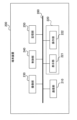
- FIG. 1 is a diagram illustrating an example of the configuration of a printing system according to an embodiment.
- FIG. 1 illustrates an example of the configuration of a printing apparatus according to an embodiment.
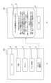
- FIG. 2 is a diagram illustrating a configuration example of a terminal device according to an embodiment.
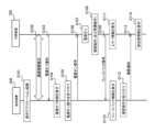
- FIG. 4 is a diagram illustrating an example of an operation sequence of a printing system according to an embodiment.
- FIG. 11 is a diagram showing a display example of an operation screen displayed on a display unit of the terminal device according to the embodiment.
- 13 is a diagram illustrating an example of an operation sequence of a printing system according to a modified example of the embodiment.
- 13A and 13B are diagrams illustrating an example of a display of an operation screen displayed on a display unit of a terminal device according to a modified example of the embodiment.
- Patent Document 1 Although a terminal device can remotely turn the power of a printing device on and off, there is a problem in that the terminal device cannot remotely detect malfunctions in the printing device.
- a printing system a printing device, a terminal device, and a program are provided that can improve the convenience of users who use the printing device.
- the printing system includes a printing device that performs a printing operation, and a terminal device that operates the printing device by communicating with the printing device.
- the terminal device transmits a specific signal to the printing device to check for the presence or absence of a malfunction in the printing device.
- the printing device performs a check operation regarding the presence or absence of the malfunction, and transmits a feedback signal indicating the result of the check operation to the terminal device.
- the terminal device can remotely detect any malfunctions in the printing device, improving convenience for users who use the printing device.
- the printing system according to this embodiment includes a printing device (also called a “printer”) 100 and a terminal device 200.
- the printing device 100 is a device that performs image processing including printing.
- the printing device 100 is also referred to as an image forming device or image recording device.
- the printing device 100 may be capable of performing image processing other than printing, such as scanning.
- the printing device 100 also has a function of communicating with the terminal device 200.
- the printing device 100 communicates with the terminal device 200 via wireless communication is mainly described, but the printing device 100 may also communicate with the terminal device 200 via wired communication.
- the printing device 100 is a small printer for home use.
- the printing device 100 may also be a large multifunction device (MFP: Multi Function Printer) installed in an office or store.
- MFP Multi Function Printer
- the printing operation performed by the printing device 100 is an operation that includes at least printing.
- the printing operation includes “printing” in which the terminal device 200 sends print data (image data) to the printing device 100 and the printing device 100 prints it.
- the printing operation also includes “copying” in which the printing device 100 prints the scan data (image data) obtained by scanning.
- the printing device 100 has a paper feed unit 101, a cover 102 including a scanner unit, a paper discharge tray 103, and an operation panel 130.
- Paper sheets set in the paper feed unit 101 are transported one by one to a printing section 121 (not shown in FIG. 1; see FIG. 2), where printing is performed, and the paper is discharged from the paper discharge tray 103.
- the cover 102 can be opened upward with the end on the paper discharge tray 103 side as a fulcrum, and the ink cartridge 5 (not shown in FIG. 1; see FIG. 2) is replaced with the cover 102 open.
- the operation panel 130 is provided at the top of the front side of the printing device 100.
- the operation panel 130 has a display section 131 that displays various information, and an operation section 132 that accepts various operations from the user (such as input of setting values and execution of image processing).
- the operation panel 130 can be opened forward with the upper end side of the operation panel 130 as a fulcrum.
- the terminal device 200 is a device capable of operating the printing device 100 by communicating with the printing device 100.
- the terminal device 200 may be a mobile terminal, such as a smartphone, a tablet terminal, or a notebook computer (PC).
- the terminal device 200 moves along with the movement of the user.
- the terminal device 200 may be a stationary terminal, such as a desktop PC.
- the terminal device 200 is a smartphone.
- the terminal devices 200 execute an operation application for operating the printing device 100.
- Each terminal device 200 executing the operation application displays an operation screen of the printing device 100.
- the operation screen of the printing device 100 includes a connection screen used when connecting to the printing device 100 and a menu screen used after connecting to the printing device 100.
- the menu screen may display operation buttons for instructing the execution of image processing for each type of image processing.
- the terminal device 200 communicates with the printing device 100 via wireless communication will be mainly described, but the terminal device 200 may also communicate with the printing device 100 via wired communication.
- communication between the printing device 100 and the terminal device 200 is indirect wireless communication via an access point (AP) 300.
- the AP 300 is also called a wireless LAN (Local Area Network) router.
- an infrastructure mode of a wireless LAN communication method is used for wireless communication between the printing device 100 and the terminal device 200.
- the terminal device 200 accesses the printing device 100 via the AP 300, and establishes a communication connection with the printing device 100 via the AP 300.
- the wireless LAN communication method may be a method that complies with the IEEE (Institute of Electrical and Electronics Engineers) 802.11 standard.
- the communication between the printing device 100 and the terminal device 200 may be direct wireless communication that does not go through the AP 300.
- an ad-hoc mode also called "access point mode”
- WiFi registered trademark
- the direct wireless communication may also be wireless communication using the Bluetooth (registered trademark; the same applies below) method.
- the printing device 100 is connected to an external power source 400 (not shown in FIG. 1; see FIG. 2) such as a commercial power source, and is supplied with power from the external power source 400.
- the printing device 100 is in either a power-off state or a power-on state. In the power-off state, power supply to at least the printing unit 121 of the printing device 100 is stopped, and printing may be impossible.
- the power-off state is also called a sleep mode or a power-saving state. Even in the power-off state, the printing device 100 can use its communication function and communicate with the terminal device 200.
- the power-on state power is supplied to the printing unit 121 of the printing device 100, and printing is possible.
- the printing device 100 may need to perform preparatory operations to start a printing operation.
- the preparatory operations include warming up and/or head cleaning. Therefore, after switching the printing device 100 from the power off information to the power on state, the printing device 100 cannot start a printing operation until the preparatory operations are completed.
- the terminal device 200 transmits a power-on signal to the printing device 100, which transitions the printing device 100 from a power-off state to a power-on state.
- the user operates the terminal device 200 to turn on the power of the printing device 100.
- the printing device 100 performs a preparatory operation.
- the printing device 100 performs a printing operation promptly.
- the printing device 100 cannot perform a printing operation even if the user moves to the location of the printing device 100. In that case, it may be a waste of the user's movement to the location of the printing device 100. Also, depending on the nature of the malfunction, it may be possible to cause the printing device 100 to perform a printing operation. For this reason, it is desirable for the user (terminal device 200) to be able to remotely grasp malfunctions in the printing device 100.
- the terminal device 200 therefore transmits a specific signal to the printing device 100 to check whether there is a malfunction in the printing device 100.
- the specific signal is a power-on signal that transitions the printing device 100 from a power-off state to a power-on state.
- the power-on signal is not only used by the terminal device 200 to remotely turn on the power of the printing device 100, but is also used by the terminal device 200 to remotely check for malfunctions in the printing device 100.
- the terminal device 200 displays an operation screen including an object that accepts a power-on operation from a user.
- the terminal device 200 transmits a power-on signal to the printing device 100.
- the printing device 100 In response to receiving a power-on signal from the terminal device 200, the printing device 100 performs a check operation to see if there is a malfunction in the printing device 100. The printing device 100 then transmits a feedback signal indicating the result of the check operation to the terminal device 200. This allows the terminal device 200 to check if there is a malfunction in the printing device 100. In this embodiment, in response to receiving a feedback signal from the printing device 100, the terminal device 200 displays feedback information based on the received feedback signal.
- the power-on signal is a signal that does not include an instruction to start a printing operation.
- the user uses the printing device 100 to copy documents that they have on hand, the user turns on the power of the printing device 100 remotely, and then moves to the location of the printing device 100 to make the copies.
- the printing device 100 performs a check operation to see if there are any malfunctions in the printing device 100, without starting a printing operation.
- the printing device 100 in response to receiving a power-on signal from the terminal device 200, the printing device 100 performs preparatory operations for starting a printing operation and checks whether there are any malfunctions in the printing device 100.
- the preparatory operations include warming up and/or head cleaning in the printing device 100.
- the printing device 100 has a communication unit 110, an image processing unit 120, an operation panel 130, a sensor unit 140, a control unit 150, a storage unit 160, and a power supply unit 170.
- the communication unit 110 performs indirect or direct wireless communication with the terminal device 200 under the control of the control unit 150.
- the communication unit 110 is a wireless LAN communication unit, but the communication unit 110 may be a Bluetooth communication unit.
- the communication unit 110 may be a wired LAN communication unit that performs wired LAN communication such as Ethernet with the terminal device 200.
- the communication unit 110 may be considered as a component that includes only hardware components (e.g., connectors, antennas, amplifiers, filters, and RF (Radio Frequency) circuits), or may be considered as a component that includes software components in addition to hardware components.
- the image processing unit 120 executes image processing under the control of the control unit 150.
- the image processing unit 120 includes a printing unit 121 and a scanner unit 122.
- types of image processing include “print” and "copy”. These image processes correspond to printing operations.
- "Copy” is an operation in which the printing unit 121 prints image data obtained by scanning an original with the scanner unit 122 onto paper.
- "Print” is an operation in which the printing unit 121 prints an image based on image data received by the communication unit 110 from the terminal device 200 or an image based on data stored in a recording medium (not shown) connected to the printing device 100.
- the image processing type may include "scanning.” "Scanning” is a function for saving image data obtained by scanning an original document with the scanner unit 122.
- the save destination may be, for example, an auxiliary storage device (from another perspective, a non-volatile memory) included in the storage unit 160 or a storage medium connected to the printing device 100. Alternatively, the save destination may be the terminal device 200.
- the type of image processing may include FAX (facsimile).
- the image processing unit 120 may further include a public network communication unit (analog modem) that performs communication via a public network.
- FAX refers to the operation of the public network communication unit printing image data received from the outside via a telephone line on paper by the printing unit 121, and the operation of the public network communication unit scanning an original document with the scanner unit 122 and transmitting the image data obtained to the outside via a telephone line.
- the printing unit 121 performs printing operations under the control of the control unit 150. For example, the printing unit 121 prints on paper set in the paper feed unit 101 and discharges the printed paper to the paper discharge tray 103.
- the printing unit 121 may have only one paper feed tray, or may have multiple paper feed trays. From another perspective, the printing unit 121 may have a function for selecting the size of the paper.
- the printing unit 121 may be configured to be capable of color (as well as monochrome and grayscale) printing, may be configured to be capable of only grayscale (and monochrome) printing, or may be configured to be capable of only monochrome printing.
- the printing unit 121 may be an inkjet printer that prints by ejecting ink, a thermal printer that prints by heating thermal paper or an ink ribbon, or an electrophotographic printer (e.g., a laser printer) that transfers toner attached to a photosensitive body irradiated with light.
- the printing unit 121 may be a line printer whose head has a length spanning the width of the paper (a direction intersecting the paper transport direction), or it may be a serial printer whose head moves in the width direction of the paper.
- the printing unit 121 is provided with detachable ink cartridges 5 (5a to 5d) of different colors.
- the ink cartridges 5 are containers filled with ink and are detachable from the printing device 100 (printing unit 121).
- the ink is not limited to liquid ink, but may be powder ink. In the latter case, the ink is also called toner, and the ink cartridge is also called a toner cartridge or toner container.
- the term “ink” also includes "toner”.
- ink cartridges 5 of different colors are installed in the printing device 100.
- the ink cartridges 5a to 5d are four ink cartridges of yellow (Y), magenta (M), cyan (C), and black (K), but the color combination is not limited to this.
- the printer 1 may be a monochrome printer, and only one ink cartridge 5 may be installed in the printer 1.
- the scanner unit 122 performs scanning under the control of the control unit 150.
- the scanner unit 122 captures (scans) an image of a document set on a document tray or an ADF (Auto Document Feeder) using an imaging device that moves along the document glass, and generates image data.
- ADF Auto Document Feeder
- the operation panel 130 includes a display unit 131 and an operation unit 132.
- the display unit 131 is configured with a liquid crystal display unit or an organic EL (Electro Luminescence) display unit.
- the display unit 131 has a relatively large number of pixels arranged regularly, and displays an image including any shape based on image data under the control of the control unit 150.
- the display unit 131 may be capable of displaying color images, may be capable of displaying only grayscale images (and monochrome images), or may be capable of displaying only monochrome images (binary images).
- the printing device 100 does not necessarily have to have the display unit 131. In that case, it may be assumed that the terminal device 200 performs operations on the printing device 100.
- the operation unit 132 includes one or more physical buttons (physical keys) and/or a touch panel in the touch panel display unit.
- the touch panel may be of an electrostatic type or a pressure-sensitive type.
- the touch panel overlaying the display unit 131 detects the position of a touch operation on the display unit 131 and outputs the detection result.
- the operation unit 132 includes a power on/off button (physical key) used to turn the power on/off of the printing device 100.
- the sensor unit 140 includes one or more sensors, and outputs sensor data obtained by the sensors.
- the sensor unit 140 includes at least one of an ink remaining amount sensor for detecting the amount of ink remaining in the printing device 100, a temperature sensor for detecting the temperature in the printing device 100 (e.g., the temperature of the printer head), a temperature sensor for detecting the room temperature around the printing device 100, a humidity sensor for detecting the humidity around the printing device 100, and a human presence sensor for detecting people around the printing device 100.
- the control unit 150 includes one or more processors and controls the entire printing device 100.
- the control unit 150 executes various processes and various controls by executing programs stored in the storage unit 160.
- the various controls include control of printing operations.
- the control unit 150 may include logic circuits and the like configured to perform only certain operations. The operations of the printing device 100 described above and below may be operations controlled by the control unit 150.
- the storage unit 160 is configured to include various memories, such as, for example, a ROM (Read Only Memory), a RAM (Random Access Memory), and an auxiliary storage device.
- ROM Read Only Memory
- RAM Random Access Memory
- the combination of the control unit 150 and the storage unit 160 may be considered as a computer.
- the programs executed by the control unit 150 are stored, for example, in the ROM of the storage unit 160 and/or the auxiliary storage device.
- FIG. 2 is merely a schematic diagram.
- the control unit 150 and the memory unit 160 may be provided in a distributed manner in multiple locations.
- each unit may have a processor included therein (a control unit that controls each unit from another perspective) and a higher-level processor (a higher-level control unit that controls the control unit of each unit).
- the control unit 150 may be regarded as a higher-level control unit, or as a combination of the control unit of each unit and the higher-level control unit.
- the power supply unit 170 supplies power to each part of the printing device 100.
- the power supply unit 170 includes a main power supply unit 171 and a standby power supply unit 172.
- the main power supply unit 171 is connected to the external power supply 400 via a cable and a power plug, and converts power from the external power supply 400 to supply power to each part of the printing device 100.
- the standby power supply unit 172 is used when the printing device 100 (main power supply unit 171) is not electrically connected to the external power supply 400.
- the standby power supply unit 172 includes a battery that can charge and discharge power, and supplies power to each part of the printing device 100 by discharging the battery.
- the printing device 100 When the printing device 100 (main power supply unit 171) is not connected to the external power supply 400, the printing device 100 is in a power-off state, and it may not be possible to turn the printing device 100 on.
- the power supply unit 170 may supply power to the communication unit 110, the sensor unit 140, the control unit 150, and the memory unit 160 without supplying power to the image processing unit 120 including the printing unit 121.
- the power supply unit 170 also supplies power to the image processing unit 120 including the printing unit 121.
- the various components of the printing device 100 are electrically connected by a bus 180.
- all components are connected to a single bus 180, but multiple buses, such as an address bus, a data bus, and a control bus, may be provided.
- the bus 180 may include a power line used to supply power from the power supply unit 170.
- An interface may also be provided between the bus 180 and each component.
- the communication unit 110 which communicates with the terminal device 200, receives a power-on signal from the terminal device 200.
- the control unit 150 performs a check operation to determine whether or not there is a malfunction in the printing device 100.
- the communication unit 110 transmits a feedback signal indicating the result of the check operation to the terminal device 200.
- the output of the sensor unit 140 may be used for the check operation. Specific examples of feedback regarding the check operation will be described later.
- Example of the configuration of the terminal device Fig. 3 is a diagram showing an example of the configuration of the terminal device 200 according to this embodiment. Here, the description of the same configuration as the above-mentioned configuration will be omitted as appropriate.
- the terminal device 200 has a communication unit 210, a display unit 221, an operation unit 222, an imaging unit 230, a control unit 240, and a storage unit 250.
- the terminal device 200 does not necessarily have to have the imaging unit 230.
- the terminal device 200 further has a power supply unit not shown.
- the power supply unit may include a battery.
- the communication unit 210 performs indirect or direct wireless communication with the printing device 100 under the control of the control unit 240.
- the communication unit 210 is a wireless LAN communication unit, but the communication unit 210 may be a Bluetooth communication unit.
- the communication unit 210 may be a wired LAN communication unit that performs wired LAN communication, such as Ethernet, with the printing device 100.
- the communication unit 210 may further include a public network communication unit that performs communication via a public network.
- the public network may include a cellular communication network.
- the public network communication unit may be a cellular communication unit.
- the display unit 221 displays an image under the control of the control unit 240.
- the operation unit 222 accepts user operations (user input).
- the display unit 221 is configured with a liquid crystal display unit or an organic EL display unit. At least a part of the operation unit 222 may be integrated with the display unit 221 to configure the touch panel display unit 220. In the following, an example in which the display unit 221 and the operation unit 222 configure the touch panel display unit 220 will be mainly described. However, at least a part of the operation unit 222 may be configured as one or more physical buttons.
- the operation unit 222 detects the position of a touch operation on the display unit 221, and outputs the detection result.
- the imaging unit 230 constitutes a camera including an image sensor such as a CCD (Charge Coupled Device) or a CMOS (Complementary Metal Oxide Semiconductor).
- the imaging unit 204 electronically captures an image under the control of the control unit 240 and outputs image data.
- the control unit 240 includes one or more processors and controls the entire terminal device 200.
- the control unit 240 executes various processes and controls by executing programs stored in the storage unit 250.
- the programs include operation applications for operating the printing device 100.
- the control unit 240 may include logic circuits and the like configured to perform only certain operations. The operations of the terminal device 200 described above and below may be operations controlled by the control unit 240.
- the storage unit 250 is configured to include various memories, such as, for example, a ROM, a RAM, and an auxiliary storage device.
- the combination of the control unit 240 and the storage unit 250 may be considered as a computer.
- the programs executed by the control unit 240 are stored, for example, in the ROM and/or the auxiliary storage device of the storage unit 250.
- the components of the terminal device 200 are electrically connected by a bus 260.
- a bus 260 In the illustrated example, all components are connected to a single bus 260, but multiple buses, such as an address bus, a data bus, and a control bus, may be provided.
- An interface may also be provided between the bus 260 and each component.
- the communication unit 210 transmits a power-on signal to the printing device 100.
- the communication unit 210 receives a feedback signal from the printing device 100 indicating the results of the checking operation regarding the presence or absence of a malfunction in the printing device 100.
- Example of Operation Sequence Fig. 4 is a diagram showing an example of an operation sequence of the printing system according to this embodiment. In this example of the sequence, it is assumed that the printing device 100 is in a power-off state.
- step S101 the control unit 240 of the terminal device 200 launches an operation application for operating the printing device 100, and displays an operation screen corresponding to the operation application on the display unit 221 of the terminal device 200.
- step S102 the control unit 240 of the terminal device 200 controls the communication unit 210 of the terminal device 200 to establish a communication connection with the printing device 100.
- the control unit 150 of the printing device 100 controls the communication unit 110 of the printing device 100 to establish a communication connection with the terminal device 200.
- control unit 240 of the terminal device 200 may control the display unit 221 of the terminal device 200 to display information indicating the connection candidate printing device 100 on the operation screen.
- control unit 240 of the terminal device 200 may control the communication unit 210 of the terminal device 200 to establish a communication connection with the selected printing device 100.
- control unit 150 of the printing device 100 may control the communication unit 110 of the printing device 100 to send a power-off notification to the terminal device 200 indicating that the printing device 100 is in a power-off state.
- the communication unit 210 of the terminal device 200 receives the power-off notification.
- step S104 in response to receiving a power-off notification from the printing device 100, the control unit 240 of the terminal device 200 may control the display unit 221 of the terminal device 200 to display information indicating that the printing device 100 is in a power-off state on the operation screen.
- the control unit 240 of the terminal device 200 may control the display unit 221 of the terminal device 200 to display an object (e.g., a power-on button) for receiving a power-on operation from the user on the operation screen.
- an object e.g., a power-on button
- step S105 the operation unit 222 of the terminal device 200 receives a power-on operation, for example, pressing (tapping) the power-on button, from the user.
- a power-on operation for example, pressing (tapping) the power-on button
- step S106 the control unit 240 of the terminal device 200 controls the communication unit 210 of the terminal device 200 to send a power-on signal to the printing device 100 in response to the operation unit 222 of the terminal device 200 receiving the power-on operation.
- the communication unit 110 of the printing device 100 receives the power-on signal.
- step S107 in response to receiving the power-on signal, the control unit 150 of the printing device 100 controls the power supply unit 170 (main power supply unit 171) of the printing device 100 to turn the printing device 100 into a power-on state.
- the power supply unit 170 (main power supply unit 171) of the printing device 100 supplies power to the image processing unit 120 of the printing device 100.
- step S108 the control unit 150 of the printing device 100 performs a check operation to determine whether or not there is a malfunction in the printing device 100.
- the printing unit 121 of the image processing unit 120 may also start a preparatory operation for starting a printing operation, such as warming up and/or head cleaning.
- the explanation will proceed assuming that the control unit 150 of the printing device 100 has determined through the check operation that there is a malfunction in the printing device 100.
- step S109 the control unit 150 of the printing device 100 controls the communication unit 110 of the printing device 100 to send a feedback signal indicating the result of the confirmation operation to the terminal device 200.
- the feedback signal includes information (such as an error code) indicating the content (type) of the malfunction in the printing device 100.
- the communication unit 210 of the terminal device 200 receives the feedback signal.
- step S110 the control unit 240 of the terminal device 200 controls the display unit 221 of the terminal device 200 to display feedback information based on a feedback signal from the printing device 100 on the operation screen.
- the display unit 221 of the terminal device 200 displays information indicating the details of the problem in the printing device 100 as feedback information on the operation screen. This allows the user to understand that there is a problem in the printing device 100 and the details of the problem based on such a display.
- the display unit 221 of the terminal device 200 may also control the display unit 221 of the terminal device 200 to display an object (for example, a confirmation button) for receiving an operation indicating that the user has confirmed the problem on the operation screen.
- an object for example, a confirmation button
- control unit 150 of the printing device 100 may control the display unit 131 of the printing device 100 to display information (error information) indicating the details of the malfunction in the printing device 100. This allows other users near the printing device 100 to understand that there is a malfunction in the printing device 100 and the details of the malfunction based on such a display.
- step S112 the operation unit 222 of the terminal device 200 accepts a confirmation operation from the user, for example, pressing (tapping) the confirmation button.
- step S113 in response to the operation unit 222 of the terminal device 200 accepting the confirmation operation, the control unit 240 of the terminal device 200 controls the communication unit 210 of the terminal device 200 to send a confirmation notification to the printing device 100.
- the communication unit 110 of the printing device 100 receives the confirmation notification.
- step S114 in response to receiving the confirmation notification, the control unit 150 of the printing device 100 controls the display unit 131 of the printing device 100 to display information indicating a solution to the problem (solution information). This allows a user who wishes to eliminate (solve) the problem to solve the problem in the printing device 100 based on the solution information displayed on the display unit 131 of the printing device 100.
- the solution information displayed by the display unit 131 of the printing device 100 is assumed to be stored in advance in the storage unit 160 of the printing device 100 for each type (content) of the problem.
- the solution information displayed by the display unit 131 of the printing device 100 may be text and/or an image that represents a solution to the problem.
- the solution information displayed by the display unit 131 of the printing device 100 may be information for accessing an external server that stores text and/or images representing the solution, for example, a code that encodes a URL (Uniform Resource Locator) (for example, a QR code (registered trademark; the same applies below)).
- a code that encodes a URL for example, a QR code (registered trademark; the same applies below)
- QR code registered trademark; the same applies below
- the user captures an image of the QR code using the imaging unit 230 of the terminal device 200.
- the control unit 240 of the terminal device 200 decodes the URL from the captured QR code and accesses the URL to obtain the text and/or images representing the solution from the external server, and controls the display unit 221 of the terminal device 200 to display the obtained text and/or images on the operation screen.
- the feedback signal transmitted from the printing device 100 to the terminal device 200 may include solution information.
- the control unit 240 of the terminal device 200 may control the display unit 221 of the terminal device 200 to further display the solution information on the operation screen as feedback information based on the feedback signal from the printing device 100.
- the checking operation includes an operation of checking the remaining amount of ink in the printing device 100.
- the control unit 150 of the printing device 100 checks the remaining amount of ink in the printing device 100 based on the output of an ink remaining amount sensor included in the sensor unit 140 of the printing device 100. If there are ink cartridges 5 of different colors, the control unit 150 of the printing device 100 checks the remaining amount of ink in each of the ink cartridges 5 of different colors.
- the checking operation further includes an operation of determining whether the remaining amount of ink is equal to or less than a predetermined amount.
- the control unit 150 of the printing device 100 may determine whether the remaining amount of ink is equal to or less than a threshold by comparing the remaining amount of ink with a preset threshold.
- the threshold may be zero or a value greater than zero.
- the threshold may be the lower limit of the remaining amount of ink at which the printing device 100 can normally perform a printing operation. If there are ink cartridges 5 of different colors, the control unit 150 of the printing device 100 may perform such a determination for each of the ink cartridges 5 of different colors.
- control unit 150 of the printing device 100 determines that the remaining ink level is below a predetermined level, it controls the communication unit 110 of the printing device 100 to send a feedback signal to the terminal device 200 indicating that the remaining ink level is below the predetermined level.
- the feedback signal may include information indicating the color (ink cartridge 5) for which the remaining ink level is below the predetermined level.
- the communication unit 210 of the terminal device 200 receives such a feedback signal.
- the control unit 240 of the terminal device 200 controls the display unit 221 of the terminal device 200 to display feedback information based on the feedback signal from the printing device 100 on the operation screen.
- the displayed feedback information may be text such as "Ink is running low” or an object (icon) indicating that ink is running low. If there are ink cartridges 5 of different colors, the displayed feedback information may include information indicating which color has less than a predetermined amount of ink remaining.
- the solution information may be information indicating how to replace an ink cartridge 5 when the remaining ink level is below a predetermined level.
- the solution information may be text and/or an image indicating how to replace an ink cartridge 5 when the remaining ink level is below a predetermined level, or may be a QR code (URL) for obtaining this text and/or image.
- the confirmation operation includes an operation of confirming at least one value (hereinafter referred to as the "temperature and humidity value”) among the temperature in the printing device 100, the room temperature around the printing device 100, and the humidity around the printing device 100.
- the control unit 150 of the printing device 100 confirms the temperature and humidity value based on the output of a temperature sensor and/or a humidity sensor included in the sensor unit 140 of the printing device 100.
- the checking operation further includes an operation of determining whether the temperature and humidity values are equal to or greater than a predetermined value.
- the control unit 150 of the printing device 100 may determine whether the temperature and humidity values are equal to or greater than a threshold value by comparing the temperature and humidity values with a preset threshold value.
- the threshold value may be the upper limit of the temperature and humidity value at which the printing device 100 can perform a normal printing operation.
- the control unit 150 of the printing device 100 may perform such a determination for each of the temperature at the printing device 100, the room temperature around the printing device 100, and the humidity around the printing device 100.
- control unit 150 of the printing device 100 determines that the temperature and humidity values are equal to or greater than the predetermined value, it controls the communication unit 110 of the printing device 100 to send a feedback signal to the terminal device 200 indicating that the temperature and humidity values are equal to or greater than the predetermined value.
- the control unit 150 of the printing device 100 may include information indicating the parameter type that is equal to or greater than the predetermined value among the temperature at the printing device 100, the room temperature around the printing device 100, and the humidity around the printing device 100.
- the communication unit 210 of the terminal device 200 receives such a feedback signal.
- the control unit 240 of the terminal device 200 controls the display unit 221 of the terminal device 200 to display feedback information based on the feedback signal from the printing device 100 on the operation screen.
- the displayed feedback information may be text such as "The printer is overheating" or an object (icon) indicating that the printer is overheating.
- the displayed feedback information may include information indicating the parameter types that are equal to or above a predetermined value among the temperature at the printing device 100, the room temperature around the printing device 100, and the humidity around the printing device 100.
- the solution information may be information indicating a method for lowering the temperature and humidity values.
- the solution information may be text and/or an image indicating a method for lowering the temperature and humidity values, or may be a QR code (URL) for obtaining the text and/or image.
- QR code URL
- the checking operation includes an operation of checking the free memory capacity in the printing device 100.
- the control unit 150 of the printing device 100 checks the free memory capacity of a storage area (e.g., RAM) in the storage unit 160 of the printing device 100 that stores print data (image data).
- a storage area e.g., RAM
- the checking operation further includes an operation of determining whether the free memory capacity is equal to or less than a predetermined amount.
- the control unit 150 of the printing device 100 may determine whether the free memory capacity is equal to or less than a threshold by comparing the free memory capacity with a preset threshold.
- the threshold may be the lower limit of the free memory capacity at which the printing device 100 can normally perform a printing operation.
- control unit 150 of the printing device 100 determines that the free memory capacity is equal to or less than the predetermined amount, it controls the communication unit 110 of the printing device 100 to send a feedback signal to the terminal device 200 indicating that the free memory capacity is equal to or less than the predetermined amount.
- the communication unit 210 of the terminal device 200 receives such a feedback signal.
- the control unit 240 of the terminal device 200 controls the display unit 221 of the terminal device 200 to display feedback information based on the feedback signal from the printing device 100 on the operation screen.
- the displayed feedback information may be text such as "There is insufficient free memory capacity," or an object (icon) indicating that there is insufficient free memory capacity.
- the solution information may be information indicating a method for increasing free memory capacity.
- the solution information may be text and/or an image indicating a method for increasing free memory capacity, or may be a QR code (URL) for obtaining the text and/or image.
- QR code URL
- the checking operation includes an operation of checking at least one of the following states (hereinafter referred to as the "parts state”): the open/closed state of the cover 102 in the printing device 100, the open/closed state of the operation panel 130, and a malfunction state of the ink cartridge 5.
- the control unit 150 of the printing device 100 checks the parts state in response to receiving a power-on signal.
- the defective state of the ink cartridge 5 may be, for example, whether the ink cartridge 5 is properly installed or not, or whether the ink cartridge 5 is a genuine product or not.
- the control unit 150 of the printing device 100 may check the open/closed state of the cover 102 based on the output of an open/closed state sensor included in the sensor unit 140 of the printing device 100.
- the control unit 150 of the printing device 100 may check the open/closed state of the operation panel 130 based on the output of an open/closed state sensor included in the sensor unit 140 of the printing device 100, or based on the control state of an actuator that drives the operation panel 130 to open and close.
- the checking operation further includes an operation for determining whether the parts state satisfies the conditions for starting a printing operation.
- the conditions for starting a printing operation may be a condition in which the printer head of the printing device 100 is able to eject ink.
- the control unit 150 of the printing device 100 may determine that the parts state does not satisfy the conditions for starting a printing operation when at least one of the following conditions is met: the cover 102 is open, the operation panel 130 is closed, the ink cartridge 5 is not properly installed, and the ink cartridge 5 is not a genuine product.
- the printing device 100 determines that the part state does not satisfy the conditions for starting the printing operation, it controls the communication unit 110 of the printing device 100 to send a feedback signal to the terminal device 200 indicating that the part state does not satisfy the conditions for starting the printing operation.
- the feedback signal may include information indicating the part state that does not satisfy the conditions for starting the printing operation.
- the communication unit 210 of the terminal device 200 receives such a feedback signal.
- the control unit 240 of the terminal device 200 controls the display unit 221 of the terminal device 200 to display feedback information based on the feedback signal from the printing device 100 on the operation screen.
- the displayed feedback information may be text such as "The cover is open” or an object (icon) indicating that the cover is open.
- the displayed feedback information may include information indicating a part state that does not satisfy the conditions for starting a printing operation.
- the solution information may be information indicating a method for satisfying the conditions for starting a print operation for a part that does not satisfy the conditions for starting a print operation.
- the solution information may be text and/or an image such as "Please close the cover,” “Please open the operation panel,” “Please install the ink properly,” or "Please install genuine ink cartridges,” or may be a QR code (URL) for obtaining the text and/or image.
- the confirmation operation includes an operation of confirming whether or not the printing device 100 (main power supply unit 171) is electrically connected to the external power supply 400.
- the control unit 150 of the printing device 100 monitors the main power supply unit 171, and in response to receiving a power-on signal, confirms whether or not the main power supply unit 171 is electrically connected to the external power supply 400. For example, if the power plug is not inserted into an outlet or if the power cable is not inserted into the printing device 100, the main power supply unit 171 is not electrically connected to the external power supply 400.
- control unit 150 of the printing device 100 controls the communication unit 110 of the printing device 100 to send a feedback signal to the terminal device 200 indicating that the printing device 100 is not electrically connected to the external power source 400.
- the communication unit 210 of the terminal device 200 receives such a feedback signal.
- the control unit 240 of the terminal device 200 controls the display unit 221 of the terminal device 200 to display feedback information based on the feedback signal from the printing device 100 on the operation screen.
- the displayed feedback information may be text such as "The printer is not connected to an outlet," or an object (icon) indicating that the printer is not connected to an outlet.
- the solution information may be information indicating a method for electrically connecting the printing device 100 (main power supply unit 171) to the external power supply 400.
- the solution information may be text and/or an image such as "Please plug the printer into the outlet," or may be a QR code (URL) for obtaining the text and/or image.
- the checking operation includes an operation of checking the reception quality of a wireless signal in wireless communication performed by the communication unit 110 of the printing device 100.
- the reception quality is, for example, the reception strength and/or SNR (Signal-to-Noise Ratio) of a wireless signal received by the communication unit 110 of the printing device 100 from the AP 300 (or the terminal device 200).
- the control unit 150 of the printing device 100 controls the communication unit 110 of the printing device 100 to measure the reception quality in response to receiving a power-on signal.
- the confirmation operation further includes an operation of determining whether the reception quality satisfies a predetermined quality.
- the control unit 150 of the printing device 100 may determine whether the reception quality is equal to or lower than a predetermined threshold by comparing the measured reception quality with a preset threshold. If the reception quality is equal to or lower than the threshold, the reception quality does not satisfy the predetermined quality.
- the threshold may be a lower limit value of the reception quality at which the printing device 100 can normally receive the print data.
- control unit 150 of the printing device 100 determines that the reception quality does not satisfy the specified quality, it controls the communication unit 110 of the printing device 100 to send a feedback signal to the terminal device 200 indicating that the reception quality does not satisfy the specified quality.
- the communication unit 210 of the terminal device 200 receives such a feedback signal.
- the control unit 240 of the terminal device 200 controls the display unit 221 of the terminal device 200 to display feedback information based on the feedback signal from the printing device 100 on the operation screen.
- the displayed feedback information may be text such as "The printer's communication status is poor" or an object (icon) indicating that the printer's communication status is poor.
- the solution information may be information indicating a method for improving the communication status of the printer.
- the solution information may be text and/or an image indicating a method for improving the communication status of the printer, or may be a QR code (URL) for obtaining the text and/or image.
- QR code URL
- the confirmation operation includes an operation of confirming whether or not another user is using the printing device 100.
- the control unit 150 of the printing device 100 confirms whether or not another user is using the printing device 100.
- control unit 150 of the printing device 100 may determine that another user is using the printing device 100 if a terminal device of another user has already established a communication connection with the communication unit 110 of the printing device 100.
- the control unit 150 of the printing device 100 may determine that another user is using the printing device 100 if it determines that a person is near the printing device 100 based on the output of a human presence sensor included in the sensor unit 140 of the printing device 100.
- control unit 150 of the printing device 100 determines that the printing device 100 is being used by another user, it controls the communication unit 110 of the printing device 100 to send a feedback signal to the terminal device 200 indicating that the printing device 100 is being used by another user.
- the feedback signal may include information indicating the content of the image processing being performed by the other user (e.g., job type).
- the communication unit 210 of the terminal device 200 receives such a feedback signal.
- the control unit 240 of the terminal device 200 controls the display unit 221 of the terminal device 200 to display feedback information based on the feedback signal from the printing device 100 on the operation screen.
- the displayed feedback information may be text such as "Another user is using the printer," or an object (icon) indicating that another user is using the printer.
- information indicating the content of the image processing (e.g., job type) being performed by the printing device 100 may be displayed.
- the displayed feedback information may be text such as "Another user is performing a copy.”
- the solution information may be information that urges the user to wait until other users have finished using the printing device 100.
- the solution information may be text and/or an image such as "Please wait until other users have finished using the printer” or "The new job will be executed once other users have finished using the printer," or may be a QR code (URL) for obtaining such text and/or image.
- FIG. 5 is a diagram showing a display example of an operation screen displayed on the display unit 221 of the terminal device 200 according to this embodiment.
- step S105 of FIG. 4 the control unit 240 of the terminal device 200 controls the display unit 221 of the terminal device 200 to display an operation screen as shown in FIG. 5(a).
- the operation screen includes information A indicating the printing device 100 to be operated, a button B for performing a print operation, a button C for performing a scan operation, a button D for performing a printer setting operation, and a button E for performing a printer power-on operation.
- button E has been selected (tapped).
- the object for checking whether or not there is a malfunction in the printing device 100 is button E for performing a printer power-on operation.
- the object for checking whether or not there is a malfunction in the printing device 100 may be button I for accepting a status inquiry operation (see FIG. 7).
- the control unit 240 of the terminal device 200 goes through steps S106 to S109 in FIG. 4, and then in step S110 in FIG. 4, controls the display unit 221 of the terminal device 200 to display an operation screen as shown in FIG. 5(b).
- the operation screen includes text F saying "The printer has been turned on", text G indicating the details of the problem with the printing device 100, and button H for receiving a user's confirmation operation regarding the details of the problem.
- text G indicating the details of the problem with the printing device 100, the contents explained in the first to seventh specific examples above are displayed.
- a scenario was assumed in which the terminal device 200 remotely operates the printing device 100 in a powered-off state to turn it on.
- a scenario is assumed in which the terminal device 200 remotely operates the printing device 100 in a powered-off state to check the latest status.
- FIG. 6 is a diagram showing an example of an operation sequence of a printing system according to this modified example. In this sequence example, it is assumed that the printing device 100 is in a power-on state.
- step S201 the control unit 240 of the terminal device 200 launches an operation application for operating the printing device 100, and displays an operation screen corresponding to the operation application on the display unit 221 of the terminal device 200.
- step S202 the control unit 240 of the terminal device 200 controls the communication unit 210 of the terminal device 200 to establish a communication connection with the printing device 100.
- the control unit 150 of the printing device 100 controls the communication unit 110 of the printing device 100 to establish a communication connection with the terminal device 200.
- control unit 240 of the terminal device 200 may control the display unit 221 of the terminal device 200 to display information indicating the connection candidate printing device 100 on the operation screen.
- control unit 240 of the terminal device 200 may control the communication unit 210 of the terminal device 200 to establish a communication connection with the selected printing device 100.
- control unit 150 of the printing device 100 may control the communication unit 110 of the printing device 100 to send a power-on notification to the terminal device 200, indicating that the printing device 100 is in a power-on state.
- the communication unit 210 of the terminal device 200 receives the power-on notification.
- the control unit 240 of the terminal device 200 may control the display unit 221 of the terminal device 200 to display information indicating that the printing device 100 is in a power-on state on the operation screen in response to receiving a power-on notification from the printing device 100.
- the control unit 240 of the terminal device 200 may control the display unit 221 of the terminal device 200 to display an object (e.g., a status inquiry button) for accepting an operation to inquire about the status of the printing device 100 from the user on the operation screen in response to receiving a power-on notification.
- an object e.g., a status inquiry button
- step S205 the operation unit 222 of the terminal device 200 receives a status inquiry operation, for example, pressing (tapping) the status inquiry button, from the user.
- a status inquiry operation for example, pressing (tapping) the status inquiry button
- step S206 the control unit 240 of the terminal device 200 controls the communication unit 210 of the terminal device 200 to send an inquiry signal to the printing device 100 in response to the operation unit 222 of the terminal device 200 accepting the status inquiry operation.
- the inquiry signal is an example of a predetermined signal.
- the communication unit 110 of the printing device 100 receives the inquiry signal.
- step S207 in response to receiving the inquiry signal, the control unit 150 of the printing device 100 performs a check operation to determine whether or not there is a malfunction in the printing device 100.
- Specific examples of the check operation are the same as the first to seventh specific examples described above.
- the control unit 150 of the printing device 100 only needs to check the latest state related to the malfunction in the printing device 100, and does not necessarily need to determine whether or not there is a malfunction.
- the control unit 150 of the printing device 100 may also determine whether or not there is a malfunction.
- the control unit 150 of the printing device 100 controls the communication unit 110 of the printing device 100 to send a feedback signal indicating the result of the checking operation to the terminal device 200.
- the feedback signal includes information indicating the state checked in the checking operation.
- the result of the checking operation (information indicating the state) may be at least one of the remaining ink amount described in the first specific example, the temperature and humidity values described in the second specific example, the free memory capacity described in the third specific example, the parts state described in the fourth specific example, the external power connection state described in the fifth specific example, the reception quality described in the sixth specific example, and the presence or absence of other users described in the seventh specific example.
- the result of the checking operation may be information indicating the content of the determined malfunction.
- the communication unit 210 of the terminal device 200 receives the feedback signal.
- step S209 the control unit 240 of the terminal device 200 controls the display unit 221 of the terminal device 200 to display feedback information based on a feedback signal from the printing device 100 on the operation screen.
- the display unit 221 of the terminal device 200 displays information indicating the state of the printing device 100 and/or information indicating the details of a malfunction in the printing device 100 as feedback information on the operation screen.
- the display control of solution information may be performed in the same manner as in the above embodiment (steps S112 to S114 in FIG. 4).
- FIG. 7 shows an example of an operation screen displayed on the display unit 221 of the terminal device 200 according to this modified example.
- step S205 of FIG. 6 the control unit 240 of the terminal device 200 controls the display unit 221 of the terminal device 200 to display an operation screen as shown in FIG. 7(a).
- the operation screen includes a button I for accepting a status inquiry operation instead of the power on button E described above.
- button I has been selected (tapped).
- the control unit 240 of the terminal device 200 goes through steps S206 to S208 in FIG. 6, and then in step S209 in FIG. 6, controls the display unit 221 of the terminal device 200 to display an operation screen as shown in FIG. 7(b).
- the operation screen includes information (text) J indicating the printer status.
- the information J indicating the printer status the contents explained in the first to seventh specific examples above are displayed.
- a scenario has been mainly described in which the terminal device 200 remotely operates the printing device 100 via a LAN (wireless LAN or preferred LAN).
- the scenario may also be such that the terminal device 200 remotely operates the printing device 100 via a WAN (Wide Area Network).
- printing may include 3D printing. That is, the printing device 100 may have a 3D printing function.
- the printing unit 121 may be a 3D printer that forms a three-dimensional object using resin and/or metal powder, etc.
- a program may be provided that causes a computer (printing device 100, terminal device 200) to execute the operations according to the above-described embodiments.
- the program may be recorded on a computer-readable medium.
- the computer-readable medium it is possible to install the program on a computer (information processing device).
- the computer-readable medium on which the program is recorded may be a non-transient recording medium.
- the non-transient recording medium is not particularly limited, and may be, for example, a recording medium such as a CD-ROM or DVD-ROM.
- the terms “based on” and “depending on/in response to” do not mean “based only on” or “depending only on,” unless otherwise specified.
- the term “based on” means both “based only on” and “based at least in part on.”
- the term “depending on” means both “based only on” and “depending at least in part on.”
- the terms “include,” “comprise,” and variations thereof do not mean including only the items listed, but may include only the items listed, or may include additional items in addition to the items listed.
- the term “or” as used in this disclosure is not intended to be an exclusive or.
- any reference to elements using designations such as “first,” “second,” etc., as used in this disclosure is not intended to generally limit the quantity or order of those elements. These designations may be used herein as a convenient way to distinguish between two or more elements. Thus, a reference to a first and second element does not imply that only two elements may be employed therein, or that the first element must precede the second element in some manner.
- articles are added by translation such as, for example, a, an, and the in English, these articles are intended to include the plural unless the context clearly indicates otherwise.
- a printing device (100) for performing a printing operation A terminal device (200) that operates the printing device (100) by communicating with the printing device (100), The terminal device (200) transmits a predetermined signal to the printing device (100) for checking whether or not there is a malfunction in the printing device (100), In response to receiving the predetermined signal, the printing device (100) performs a checking operation regarding the presence or absence of the malfunction, and transmits a feedback signal indicating a result of the checking operation to the terminal device (200).
- the predetermined signal is a power-on signal that transitions the printing device (100) from a power-off state to a power-on state,
- the terminal device (200) displaying an operation screen including an object for receiving a power-on operation from a user;
- the power-on signal is a signal that does not include an instruction to start the printing operation,
- the predetermined signal is an inquiry signal for inquiring about the status of the printing device (100), The printing system according to claim 1, wherein the printing device (100) performs the confirmation operation in response to receiving the inquiry signal.
- the terminal device (200) displaying an operation screen including an object for receiving an inquiry operation from a user;
- Appendix 8 The printing system according to any one of appendixes 1 to 7, wherein the checking operation includes an operation of checking the remaining amount of ink in the printing device (100).
- the checking operation further includes an operation of determining whether the remaining amount of ink is equal to or less than a predetermined amount, The printing system described in Appendix 8, wherein when it is determined that the remaining amount of ink is equal to or less than the predetermined amount, the printing device (100) transmits the feedback signal indicating that the remaining amount of ink is equal to or less than the predetermined amount to the terminal device (200).
- Appendix 10 The printing system described in any one of appendix 1 to 9, wherein the confirmation operation includes an operation of confirming at least one value of the temperature at the printing device (100), the room temperature around the printing device (100), and the humidity around the printing device (100).
- the checking operation further includes an operation of determining whether the value is equal to or greater than a predetermined value, The printing system described in Appendix 10, wherein when it is determined that the value is greater than or equal to the predetermined value, the printing device (100) transmits the feedback signal indicating that the value is greater than or equal to the predetermined value to the terminal device (200).
- Appendix 12 The printing system according to any one of appendixes 1 to 11, wherein the checking operation includes an operation of checking free memory capacity in the printing device (100).
- the checking operation further includes an operation of determining whether the free memory capacity is equal to or less than a predetermined amount, The printing system described in Appendix 12, wherein when it is determined that the free memory capacity is equal to or less than the predetermined amount, the printing device (100) transmits the feedback signal indicating that the free memory capacity is equal to or less than the predetermined amount to the terminal device (200).
- Appendix 14 The printing system described in any one of appendixes 1 to 13, wherein the confirmation operation includes an operation of checking at least one of the following: whether a cover in the printing device (100) is open or closed; whether an operation panel in the printing device (100) is open or closed; and whether an ink cartridge in the printing device (100) is defective.
- the checking operation further includes an operation of determining whether the state satisfies a condition under which the printing operation can be started; The printing system described in Appendix 14, wherein when it is determined that the state does not satisfy the condition, the printing device (100) transmits the feedback signal indicating that the state does not satisfy the condition to the terminal device (200).
- the printing device (100) includes a standby power supply for use when the printing device (100) is not electrically connected to an external power supply;
- the checking operation includes an operation of checking whether the printing device (100) is electrically connected to an external power source; 16.
- a printing system according to any one of claims 1 to 15.
- Appendix 17 The printing system described in Appendix 16, wherein the printing device (100) transmits the feedback signal indicating that the printing device (100) is not electrically connected to the external power source to the terminal device (200) when the printing device (100) is not electrically connected to the external power source.
- the printing device (100) communicates with the terminal device (200) by wireless communication;
- the printing system according to any one of appendixes 1 to 17, wherein the checking operation includes an operation of checking a reception quality of a wireless signal in the wireless communication.
- the checking operation further includes an operation of determining whether the reception quality satisfies a predetermined quality, The printing system described in Appendix 18, wherein when it is determined that the reception quality does not satisfy the specified quality, the printing device (100) transmits the feedback signal indicating that the reception quality does not satisfy the specified quality to the terminal device (200).
- Appendix 21 The printing system described in Appendix 20, wherein when it is determined that the printing device (100) is being used by another user, the printing device (100) transmits the feedback signal indicating that the printing device (100) is being used by another user to the terminal device (200).
- the printing device (100) After determining that the printing device (100) has a defect through the checking operation, the printing device (100) displays information showing a solution to the defect; The printing system according to claim 22, wherein the terminal device (200) displays information indicating the content of the defect as the feedback information.
- the terminal device (200) determines that the user has confirmed the content of the defect, the terminal device (200) transmits a confirmation notification to the printing device (100); 24.
- the communication unit receives a predetermined signal for checking whether or not there is a malfunction in the printing device (100) from the terminal device (200),
- the control unit performs a confirmation operation regarding the presence or absence of the malfunction in response to receiving the predetermined signal,
- the communication unit transmits a feedback signal indicating a result of the confirmation operation to the terminal device (200).
- Printer 5 Ink cartridge 100: Printing device 101: Paper feed unit 102: Cover 103: Paper output tray 110: Communication unit 120: Image processing unit 121: Printing unit 122: Scanner unit 130: Operation panel 131: Display unit 132: Operation unit 140: Sensor unit 150: Control unit 160: Memory unit 170: Power supply unit 171: Main power supply unit 172: Backup power supply unit 180: Bus 200: Terminal device 204: Imaging unit 210: Communication unit 220: Touch panel display unit 221: Display unit 222: Operation unit 230: Imaging unit 240: Control unit 250: Memory unit 260: Bus 300: AP 400: External power supply
Landscapes
- Engineering & Computer Science (AREA)
- Theoretical Computer Science (AREA)
- Human Computer Interaction (AREA)
- Physics & Mathematics (AREA)
- General Engineering & Computer Science (AREA)
- General Physics & Mathematics (AREA)
- Accessory Devices And Overall Control Thereof (AREA)
Priority Applications (3)
| Application Number | Priority Date | Filing Date | Title |
|---|---|---|---|
| PCT/JP2023/012786 WO2024201771A1 (ja) | 2023-03-29 | 2023-03-29 | 印刷システム、印刷装置、端末装置、及びプログラム |
| JP2024563896A JPWO2024204607A1 (cg-RX-API-DMAC7.html) | 2023-03-29 | 2024-03-28 | |
| PCT/JP2024/012805 WO2024204607A1 (ja) | 2023-03-29 | 2024-03-28 | 印刷システム、印刷装置、端末装置、及びプログラム |
Applications Claiming Priority (1)
| Application Number | Priority Date | Filing Date | Title |
|---|---|---|---|
| PCT/JP2023/012786 WO2024201771A1 (ja) | 2023-03-29 | 2023-03-29 | 印刷システム、印刷装置、端末装置、及びプログラム |
Publications (1)
| Publication Number | Publication Date |
|---|---|
| WO2024201771A1 true WO2024201771A1 (ja) | 2024-10-03 |
Family
ID=92903613
Family Applications (2)
| Application Number | Title | Priority Date | Filing Date |
|---|---|---|---|
| PCT/JP2023/012786 Ceased WO2024201771A1 (ja) | 2023-03-29 | 2023-03-29 | 印刷システム、印刷装置、端末装置、及びプログラム |
| PCT/JP2024/012805 Ceased WO2024204607A1 (ja) | 2023-03-29 | 2024-03-28 | 印刷システム、印刷装置、端末装置、及びプログラム |
Family Applications After (1)
| Application Number | Title | Priority Date | Filing Date |
|---|---|---|---|
| PCT/JP2024/012805 Ceased WO2024204607A1 (ja) | 2023-03-29 | 2024-03-28 | 印刷システム、印刷装置、端末装置、及びプログラム |
Country Status (2)
| Country | Link |
|---|---|
| JP (1) | JPWO2024204607A1 (cg-RX-API-DMAC7.html) |
| WO (2) | WO2024201771A1 (cg-RX-API-DMAC7.html) |
Citations (6)
| Publication number | Priority date | Publication date | Assignee | Title |
|---|---|---|---|---|
| JPH0920047A (ja) * | 1995-07-07 | 1997-01-21 | Ricoh Co Ltd | 画像形成装置 |
| JP2009086976A (ja) * | 2007-09-28 | 2009-04-23 | Canon Imaging Systems Inc | デバイス制御装置、デバイスの制御方法及びプログラム |
| JP2010066908A (ja) * | 2008-09-09 | 2010-03-25 | Ricoh Co Ltd | 画像形成処理システム、画像形成処理システムの制御方法及びこれに用いられる遠隔操作プログラム |
| JP2015108940A (ja) * | 2013-12-04 | 2015-06-11 | 株式会社リコー | 情報処理システム、情報処理装置、情報処理方法及びプログラム |
| JP2015191474A (ja) * | 2014-03-28 | 2015-11-02 | キヤノン株式会社 | 印刷システム、携帯端末、画像形成装置及びその制御方法、並びにプログラム |
| JP2020001220A (ja) * | 2018-06-26 | 2020-01-09 | 富士ゼロックス株式会社 | 画像処理装置、画像処理システム、及び画像処理プログラム |
Family Cites Families (3)
| Publication number | Priority date | Publication date | Assignee | Title |
|---|---|---|---|---|
| JP2015003451A (ja) * | 2013-06-21 | 2015-01-08 | キヤノン株式会社 | 画像形成装置、画像形成装置の制御方法、及びプログラム |
| JP2017022488A (ja) * | 2015-07-08 | 2017-01-26 | 株式会社リコー | 画像取得装置、画像形成装置、画像取得システム、画像取得方法、及びプログラム |
| JP7652572B2 (ja) * | 2021-01-20 | 2025-03-27 | キヤノン株式会社 | 画像形成システム |
-
2023
- 2023-03-29 WO PCT/JP2023/012786 patent/WO2024201771A1/ja not_active Ceased
-
2024
- 2024-03-28 WO PCT/JP2024/012805 patent/WO2024204607A1/ja not_active Ceased
- 2024-03-28 JP JP2024563896A patent/JPWO2024204607A1/ja active Pending
Patent Citations (6)
| Publication number | Priority date | Publication date | Assignee | Title |
|---|---|---|---|---|
| JPH0920047A (ja) * | 1995-07-07 | 1997-01-21 | Ricoh Co Ltd | 画像形成装置 |
| JP2009086976A (ja) * | 2007-09-28 | 2009-04-23 | Canon Imaging Systems Inc | デバイス制御装置、デバイスの制御方法及びプログラム |
| JP2010066908A (ja) * | 2008-09-09 | 2010-03-25 | Ricoh Co Ltd | 画像形成処理システム、画像形成処理システムの制御方法及びこれに用いられる遠隔操作プログラム |
| JP2015108940A (ja) * | 2013-12-04 | 2015-06-11 | 株式会社リコー | 情報処理システム、情報処理装置、情報処理方法及びプログラム |
| JP2015191474A (ja) * | 2014-03-28 | 2015-11-02 | キヤノン株式会社 | 印刷システム、携帯端末、画像形成装置及びその制御方法、並びにプログラム |
| JP2020001220A (ja) * | 2018-06-26 | 2020-01-09 | 富士ゼロックス株式会社 | 画像処理装置、画像処理システム、及び画像処理プログラム |
Also Published As
| Publication number | Publication date |
|---|---|
| JPWO2024204607A1 (cg-RX-API-DMAC7.html) | 2024-10-03 |
| WO2024204607A1 (ja) | 2024-10-03 |
Similar Documents
| Publication | Publication Date | Title |
|---|---|---|
| US11281409B2 (en) | Communication device, and method and computer readable medium for the same | |
| JP6590754B2 (ja) | 通信装置、制御方法およびプログラム | |
| JP2016091083A (ja) | 印刷制御装置、印刷制御方法及びプログラム | |
| JP6028468B2 (ja) | 画像処理システムおよび画像処理方法 | |
| JP2017211830A (ja) | 機能実行プログラム及び情報処理装置 | |
| US9497350B2 (en) | Image processing apparatus, method for controlling image processing apparatus, and storage medium | |
| JP2010023367A (ja) | 画像形成装置及びその制御プログラム | |
| US10235107B2 (en) | Display system for controlling power state of display, image forming apparatus, program, and display power state control method | |
| JP2011178117A (ja) | 画像形成装置、及び給紙装置互換判定処理プログラム | |
| WO2024204607A1 (ja) | 印刷システム、印刷装置、端末装置、及びプログラム | |
| JP6287536B2 (ja) | 画像形成システム | |
| JP2024164245A (ja) | 画像処理システム、画像処理装置、端末装置、及びプログラム | |
| JP6915426B2 (ja) | 情報処理装置 | |
| US20150102771A1 (en) | Power receiving apparatus and power receiving method | |
| JP6833944B2 (ja) | 通信装置、制御方法およびプログラム | |
| US9013737B2 (en) | Image reading device and non-transitory computer readable medium storing image reading control program | |
| JP7039912B2 (ja) | プログラム | |
| JP2017157133A (ja) | 表示入力装置およびそれを備えた画像形成装置 | |
| JP7328266B2 (ja) | 通信装置、制御方法およびプログラム | |
| JP7600472B1 (ja) | 携帯端末装置、画像処理装置及びプログラム | |
| JP2019201385A (ja) | 画像形成装置及び画像形成装置の制御方法 | |
| JP2013146874A (ja) | 画像形成装置 | |
| WO2024075734A1 (ja) | 画像処理装置、端末装置、プログラム、及び印刷システム | |
| WO2025203487A1 (ja) | 画像処理装置、端末装置、プログラム、及び印刷システム | |
| JP2019016965A (ja) | 情報処理装置、制御方法及びプログラム |
Legal Events
| Date | Code | Title | Description |
|---|---|---|---|
| 121 | Ep: the epo has been informed by wipo that ep was designated in this application |
Ref document number: 23930411 Country of ref document: EP Kind code of ref document: A1 |
|
| NENP | Non-entry into the national phase |
Ref country code: DE |
|
| 122 | Ep: pct application non-entry in european phase |
Ref document number: 23930411 Country of ref document: EP Kind code of ref document: A1 |
|
| NENP | Non-entry into the national phase |
Ref country code: JP |