WO2024190662A1 - 保持装置 - Google Patents
保持装置 Download PDFInfo
- Publication number
- WO2024190662A1 WO2024190662A1 PCT/JP2024/009041 JP2024009041W WO2024190662A1 WO 2024190662 A1 WO2024190662 A1 WO 2024190662A1 JP 2024009041 W JP2024009041 W JP 2024009041W WO 2024190662 A1 WO2024190662 A1 WO 2024190662A1
- Authority
- WO
- WIPO (PCT)
- Prior art keywords
- space
- holding device
- holding
- communication hole
- wind
- Prior art date
- Legal status (The legal status is an assumption and is not a legal conclusion. Google has not performed a legal analysis and makes no representation as to the accuracy of the status listed.)
- Ceased
Links
Images




Classifications
-
- H—ELECTRICITY
- H02—GENERATION; CONVERSION OR DISTRIBUTION OF ELECTRIC POWER
- H02J—ELECTRIC POWER NETWORKS; CIRCUIT ARRANGEMENTS OR SYSTEMS FOR SUPPLYING OR DISTRIBUTING ELECTRIC POWER; SYSTEMS FOR STORING ELECTRIC ENERGY
- H02J7/00—Circuit arrangements for charging or discharging batteries or for supplying loads from batteries
- H02J7/70—Circuit arrangements for charging or discharging batteries or for supplying loads from batteries characterised by the mechanical construction
- H02J7/751—Circuit arrangements for charging or discharging batteries or for supplying loads from batteries characterised by the mechanical construction concerning the insertion or the connection of the batteries
-
- H—ELECTRICITY
- H01—ELECTRIC ELEMENTS
- H01M—PROCESSES OR MEANS, e.g. BATTERIES, FOR THE DIRECT CONVERSION OF CHEMICAL ENERGY INTO ELECTRICAL ENERGY
- H01M10/00—Secondary cells; Manufacture thereof
- H01M10/60—Heating or cooling; Temperature control
- H01M10/65—Means for temperature control structurally associated with the cells
- H01M10/656—Means for temperature control structurally associated with the cells characterised by the type of heat-exchange fluid
- H01M10/6561—Gases
- H01M10/6563—Gases with forced flow, e.g. by blowers
-
- H—ELECTRICITY
- H01—ELECTRIC ELEMENTS
- H01M—PROCESSES OR MEANS, e.g. BATTERIES, FOR THE DIRECT CONVERSION OF CHEMICAL ENERGY INTO ELECTRICAL ENERGY
- H01M50/00—Constructional details or processes of manufacture of the non-active parts of electrochemical cells other than fuel cells, e.g. hybrid cells
- H01M50/20—Mountings; Secondary casings or frames; Racks, modules or packs; Suspension devices; Shock absorbers; Transport or carrying devices; Holders
- H01M50/244—Secondary casings; Racks; Suspension devices; Carrying devices; Holders characterised by their mounting method
-
- H—ELECTRICITY
- H02—GENERATION; CONVERSION OR DISTRIBUTION OF ELECTRIC POWER
- H02J—ELECTRIC POWER NETWORKS; CIRCUIT ARRANGEMENTS OR SYSTEMS FOR SUPPLYING OR DISTRIBUTING ELECTRIC POWER; SYSTEMS FOR STORING ELECTRIC ENERGY
- H02J2207/00—Details of circuit arrangements for charging or discharging batteries or supplying loads from batteries
- H02J2207/50—Charging of capacitors, supercapacitors, ultra-capacitors or double layer capacitors
Definitions
- the present invention relates to a retaining device.
- the present invention claims priority based on Japanese Patent Application No. 2023-039311, filed on March 14, 2023, the contents of which are incorporated herein by reference.
- Patent Document 1 discloses a charger that includes a tray for placing a battery and a control device that controls charging of the battery.
- the control device is disposed below a first inclined surface of the tray.
- the control device is disposed in a substantially closed housing.
- the present application aims to solve the above problem by promoting air flow in the internal space of the holding device.
- a holding device (e.g., holding device 1 in the embodiment) has a first part (e.g., first part 31 in the embodiment) that holds a first surface (e.g., bottom surface 12 in the embodiment) of an electric storage device (e.g., electric storage device 10 in the embodiment) facing a first direction, and a second part (e.g., second part 32 in the embodiment) that holds a second surface (e.g., rear surface 16 in the embodiment) of the electric storage device facing a second direction intersecting the first direction, and is a holding device including a holding part (e.g., holding part 2 in the embodiment) that detachably holds the electric storage device, and when the holding device is placed, the holding device is configured to hold the electric storage device in a position where the electric storage device is placed.
- a holding part e.g., holding part 31 in the embodiment
- an electric storage device e.g., electric storage device 10 in the embodiment
- a second part e.g., second part 32 in the embodiment
- the holding device has a bottom (e.g., bottom 3 in the embodiment) facing a placement surface (e.g., placement surface F in the embodiment), and inside the holding device, an internal space (e.g., internal space 40 in the embodiment) is formed which includes a first space (e.g., first space 41 in the embodiment) partitioned by the first part and the bottom, and a second space (e.g., second space 42 in the embodiment) partitioned by the second part and the bottom and communicating with the first space, and the holding device has a wind-generating section (e.g., wind-generating section 80 in the embodiment) in the second space which promotes the flow of air through the first space and the second space.
- a wind-generating section e.g., wind-generating section 80 in the embodiment
- the holding device described in (1) above may further include a partition (e.g., partition 45 in the embodiment) that partitions the second space into a wind-generating part arrangement space in which the wind-generating part is arranged (e.g., wind-generating part arrangement space 43 in the embodiment) and a wind-generating part non-arrangement space in which the wind-generating part is not arranged (e.g., wind-generating part non-arrangement space 44 in the embodiment).
- a partition e.g., partition 45 in the embodiment
- the holding device described in (2) above may further include a first terminal (e.g., first terminal 18 in the embodiment) provided on the capacitor and a second terminal (e.g., second terminal 35 in the embodiment) that is detachable from the first terminal provided on the capacitor in the non-wind-raising portion space.
- a first terminal e.g., first terminal 18 in the embodiment
- a second terminal e.g., second terminal 35 in the embodiment
- the first part and the second part may extend in a direction that intersects obliquely with the bottom part.
- a first angle (e.g., first angle A1 in the embodiment) which is the smallest angle between the first part and the bottom may be smaller than a second angle (e.g., second angle A2 in the embodiment) which is the smallest angle between the second part and the bottom.
- the holding portion is configured to attach and detach the storage battery in a direction along the first portion (e.g., the direction of arrow V1 in the embodiment), the holding device further includes a front portion (e.g., front portion 4 in the embodiment) that is positioned lower than the holding portion when viewed from the direction along the first portion and has a surface facing forward of the holding device (e.g., front surface 4a in the embodiment), and the first space may be partitioned by the front portion in addition to the first portion and the bottom.
- a front portion e.g., front portion 4 in the embodiment
- the first space may be partitioned by the front portion in addition to the first portion and the bottom.
- the lower end of the front portion (e.g., lower end 4b in the embodiment) may be provided at a position higher than the placement surface, and the bottom portion may have a connection portion (e.g., connection portion 61 in the embodiment) that is connected to the lower end of the front portion and spaced apart from the placement surface.
- a connection portion e.g., connection portion 61 in the embodiment
- connection portion may be formed with a first communication hole (e.g., the first communication hole in the embodiment) that connects the external space of the holding device with the first space.
- the first communication hole may open so as to face downward rather than horizontally.
- connection portion may have a protrusion (e.g., protrusion 64 in the embodiment) that protrudes downward forward of the first communication hole.
- the holding device described in any of (1) to (10) above may further include a rear portion (e.g., rear portion 5 in the embodiment) that is disposed on the opposite side of the second space from the second portion and has a surface facing rearward of the holding device (e.g., rear surface 5a in the embodiment), and the second space may be partitioned by the rear portion in addition to the second portion and the bottom portion.
- a rear portion e.g., rear portion 5 in the embodiment
- the second space may be partitioned by the rear portion in addition to the second portion and the bottom portion.
- the rear portion may have a rear upper portion (e.g., rear upper portion 71 in the embodiment) having a rear end surface (e.g., rear end surface 71a in the embodiment), and a rear lower portion (e.g., rear lower portion 72 in the embodiment) that is disposed lower than the rear upper portion and recessed forward.
- a rear upper portion e.g., rear upper portion 71 in the embodiment
- a rear lower portion e.g., rear lower portion 72 in the embodiment
- a second communication hole (e.g., second communication hole 73 in the embodiment) that connects the external space of the holding device to the second space may be formed in the rear lower portion.
- the second communication hole may open so as to face downward rather than horizontally.
- the wind-raising section may be attached to a portion of the rear lower section that faces the second space (e.g., portion 72a in the embodiment).
- the holding device described in any of (1) to (15) above may further include at least one of a power conversion device (e.g., power conversion device 81 in the embodiment) that is provided in the first space so as to be capable of transmitting power to the electric storage device held in the holding portion, and a control device (e.g., control device 82 in the embodiment) that controls the power conversion device.
- a power conversion device e.g., power conversion device 81 in the embodiment
- a control device e.g., control device 82 in the embodiment
- the second space of the internal space of the holding device which is connected to the first space, is provided with an air-raising section that promotes the flow of air through the first space and the second space, thereby promoting the flow of air in both the first space and the second space. Therefore, the flow of air in the internal space of the holding device can be promoted.
- the air flow path is narrowed by the partition, making it possible to increase the air flow speed. For example, if the air flow speed is the same, a fan with a smaller output (power consumption) can be used as the wind generating section.
- the holding device of the present invention described in (3) above can utilize the space where the air-raising portion is not arranged as a space for arranging the second terminal. In addition, it can prevent the air flow from being blocked by the second terminal.
- the holding device of the present invention described above in (4) allows the user to insert and remove the storage battery at an angle along the first or second part, making it easier for the user to attach and remove the storage battery.
- the holding part can also distribute the load of the storage battery.
- the holding device described in (5) above of the present invention makes it easier to make the first space wider than the second space, compared to when the first angle is equal to or larger than the second angle. In addition, it makes it easier to make the second space wider than the first space.
- the retention device of the present invention described above in (6) narrows the air flow path at the front, making it possible to increase the air flow speed.
- the air flow path is further narrowed by the connecting portion, making it possible to further increase the air flow speed.
- the holding device described in (8) above of the present invention compared to when the first communication hole is formed in the front part, abnormal noises caused by air passing through the first communication hole are less likely to be transmitted to the front side.
- the first communication hole is formed in the connection part that is provided away from the mounting surface, air can be drawn in through the first communication hole.
- the first communication hole is formed in a position recessed from the front part, it is possible to prevent water that runs down the front part from being sucked in through the first communication hole.
- the holding device described in (9) above of the present invention can prevent water and dust from entering through the first communication hole, compared to when the first communication hole opens so as to face horizontally or upward.
- the retaining device described in (10) above of the present invention allows the convex portion to block water that runs down the front portion from reaching the first communication hole.
- the retention device of the present invention described above in (11) narrows the air flow path at the rear, making it possible to increase the air flow speed.
- the air flow path is further narrowed by the rear lower portion, making it possible to further increase the air flow speed.
- the retaining device described in (13) above of the present invention compared to when the second communication hole is formed in the upper rear portion, abnormal noises caused by air passing through the second communication hole are less likely to be transmitted to the rear side.
- the second communication hole is formed in the lower rear portion that is recessed on the forward side, air can be exhausted from the second communication hole.
- the second communication hole is formed in a position recessed from the upper rear portion, water that runs down the upper rear portion can be prevented from entering the second communication hole.
- the holding device of the present invention described above in (14) can prevent water and dust from entering through the second communication hole, compared to when the second communication hole is opened to face horizontally or upward. For example, even when two holding devices are arranged so that their rear lower parts face each other, the exhaust gases from the respective second communication holes do not collide head-on, making it difficult to impede the exhaust flow.
- the retaining device of the present invention described above in (15) allows the rear lower portion to protect the wind-generating portion from external factors. In addition, this contributes to making the retaining device smaller, compared to when the wind-generating portion is attached to the portion of the rear lower portion opposite the portion facing the second space (in other words, the portion facing the external space).
- the first space can be utilized as a space for arranging at least one of the power conversion device and the control device (e.g., the object to be cooled).
- the control device e.g., the object to be cooled.
- forced air cooling of the first space can suppress an excessive temperature rise in the internal space caused by heat generation in the electric circuits of at least one of the power conversion device and the control device, and a reduction in the lifespan of electronic components can be avoided.
- FIG. FIG. 4 is a perspective view of the holding device according to the embodiment, seen from below and rearward;
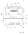
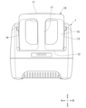
- FIG. FIG. 4 is a front view of the holding device according to the embodiment holding the electric storage device.
- FIG. 4 is a side view of a state in which the holding device according to the embodiment holds the electric storage device.
- 5A to 5C are diagrams illustrating air flow in an internal space of the holding device according to the embodiment.
- 6A to 6C are diagrams illustrating the flow of water droplets running down the front part of the holding device according to the embodiment.
- FIG. 13 is a diagram showing two holding devices according to the embodiment arranged so that their rear lower portions face each other.
- a holding device that detachably holds a storage battery (secondary battery) such as a battery as a storage battery.
- “Detachable” means that it can be attached and detached.
- the holding device of the embodiment is a detachable type that does not require separate tools for attachment and detachment.
- expressions indicating relative or absolute arrangement such as “parallel,” “orthogonal,” “center,” and “coaxial” not only mean such an arrangement strictly, but also include a state in which there is a relative displacement with a tolerance or an angle or distance that provides the same function.
- the scale of each component has been appropriately changed to make each component recognizable in size.
- the holding device 1 includes a holding section 2 that detachably holds the storage battery 10, a bottom section 3 that faces a mounting surface F when the holding device 1 is placed, a front section 4 having a front surface 4a facing forward of the holding device 1, a rear section 5 having a rear surface 5a facing rearward of the holding device 1, an upper section 6 having an upper surface 6a facing upward of the holding device 1, a left section 7 having a left surface 7a facing leftward of the holding device 1, and a right section 8 having a right surface 8a facing rightward of the holding device 1.
- the mounting surface F on which the holding device 1 is placed is a flat ground or floor surface (horizontal surface).
- three axial directions that are orthogonal to each other as shown in the figure are defined as the front-rear direction, the left-right direction, and the up-down direction.
- the up-down direction is also called the vertical direction.
- the downward direction in the up-down direction corresponds to the direction of gravity.
- An opening 20 is formed in the holding device 1 from the front 4 to the top 6.
- a storage space 21 is formed through the opening 20, and has a shape that conforms to the outer shape of the electric storage device 10.
- the storage space 21 is recessed from the top 6 of the holding device 1.
- the storage space 21 is formed by a number of surfaces (specifically, a bottom surface (top surface 31a of the first part 31) and three side surfaces (the inner surfaces of the left and right side parts 7, 8, and the front surface 32a of the second part 32) that rise respectively from the left and right edges and rear end of the bottom surface. At least one of the three side surfaces does not have to be flat.
- the left side 7 and right side 8 are formed with their upper ends inclined (rising upwards towards the rear) so that they become higher from the front to the rear.
- the vertical length of the storage space 21 also becomes longer from the front to the rear, with the rear side being the longest.
- the electric storage device 10 is configured as a unit using a single battery pack.
- the electric storage device 10 is a lithium ion battery.
- the electric storage device 10 can be used as a power source for a traction motor mounted on a two-wheeled or four-wheeled electric vehicle.
- the electric storage device 10 can be used for various purposes, not limited to the above.
- the electric storage device 10 can be applied to electrical equipment other than electric vehicles.
- the storage battery 10 has an approximately rectangular parallelepiped shape overall.
- the respective faces of the storage battery 10 are defined as the top face 11, bottom face 12, left face 13, right face 14, front face 15, and rear face 16, based on the state in which the storage battery 10 is accommodated in the holding device 1.
- the left-right length of the storage battery 10 is approximately the same as the left-right length of the accommodation space 21.
- the up-down length of the storage battery 10 is approximately the same as the maximum up-down length of the accommodation space 21.
- the front-rear length of the storage battery 10 is approximately the same as the maximum front-rear length of the accommodation space 21.
- the electric storage device 10 is accommodated in the accommodation space 21 through the opening 20.
- the top surface 11 and the front surface 15 of the electric storage device 10 are exposed from the holding device 1.
- a handle 17 is provided on the front surface 15 of the electric storage device 10.
- a user can hold the handle 17 and carry the electric storage device 10 in a hanging state with the rear surface 16 facing downward.
- the electric storage device 10 can stand on its own with the rear surface 16 in contact with the ground or floor.
- a first terminal 18 is provided on the upper part of the rear surface 16 of the storage battery 10.
- the first terminal 18 comprises a plurality of generally flat metal terminals spaced apart from each other in the left-right direction.
- the first terminal 18 is a concave receptacle (female connector) that extends in the left-right direction.
- the holding portion 2 has a first portion 31 that holds the lower surface 12 of the storage battery 10 (an example of a first surface facing the first direction of the storage battery 10) and a second portion 32 that holds the rear surface 16 of the storage battery 10 (an example of a second surface facing the second direction intersecting the first direction of the storage battery 10).
- the holding portion 2 is generally L-shaped in cross section.
- the left-right lengths of the first portion 31 and the second portion 32 are approximately the same as the left-right length of the storage space 21.
- the front-rear length of the first portion 31 is approximately the same as the front-rear length of the storage space 21.
- the up-down length of the second portion 32 is approximately the same as the maximum length of the storage space 21 in the up-down direction.
- the holding portion 2 is provided so that the storage battery 10 can be attached and detached in a direction V1 along the first portion 31.
- the bottom surface 12 of the storage battery 10 abuts against the top surface 31a of the first portion 31 when the storage battery 10 is accommodated.
- the rear surface 16 of the storage battery 10 abuts against the front surface 32a of the second portion 32 when the storage battery 10 is accommodated.
- the top surface 31a of the first portion 31 is smoothly configured so that the bottom surface 12 of the storage battery 10 can slide smoothly along the top surface 31a.
- a number of parallel ribs or rails extending in the front-rear direction are protruded from the top surface of the first portion 31 so that the contact area between the top surface 31a of the first portion 31 and the bottom surface 12 of the storage battery 10 is reduced.
- the first and second parts 31 and 32 extend in a direction that intersects obliquely with the bottom 3.
- the top surface of the first part 31 slopes downward toward the rear.
- the second part 32 extends rearward and upward from the rear end of the first part 31 at approximately a right angle to the first part 31.
- the smallest angle between the first part 31 and the bottom part 3 in a cross-sectional view is defined as the first angle A1.
- the first angle A1 is the smallest angle between the top surface 31a of the first part 31 and a plane parallel to the bottom body 60 in a cross-sectional view.
- the smallest angle between the second part 32 and the bottom part 3 in a cross-sectional view is defined as the second angle A2.
- the second angle A2 is the smallest angle between the front surface 32a of the second part 32 and a plane parallel to the bottom body 60 in a cross-sectional view.
- the first angle A1 is smaller than the second angle A2.
- the front surface 32a of the second portion 32 is provided with an area 33 where a label can be attached.
- a through hole 34 that penetrates the second portion 32 in the front-rear direction is formed in the upper portion of the second portion 32.
- the through hole 34 extends in the left-right direction corresponding to the position of the first terminal 18 of the storage battery 10.
- a second terminal 35 that is detachable from the first terminal 18 provided on the storage battery 10 is provided on the upper rear surface of the second portion 32.
- the second terminal 35 is attached to the second part 32 by a fastening member such as a bolt 37 via a bracket 36.
- a fastening member such as a bolt 37
- the bracket 36 to which the second terminal 35 is fixed is placed on the rear surface of the second part 32.
- the bolt 37 is tightened from the outside of the retaining device 1 (the front side of the second part 32) into the female threaded portion (not shown) of the bracket 36. This allows the second terminal 35 to be fixed to the second part 32 via the bracket 36.
- the second terminal 35 comprises a plurality of generally flat metal terminals spaced apart from one another in the left-right direction.
- the second terminal 35 is a plug (male connector) extending in the left-right direction.
- the second terminal 35 protrudes forward (specifically, forward and upward) from the through hole 34. The portion of the second terminal 35 that protrudes forward from the through hole 34 is always exposed.
- a user pushes the storage battery 10 housed in the housing space 21 in the direction of arrow V1 along the top surface of the first part 31.
- This causes the plug (second terminal 35) of the holding device 1 to fit into the first terminal 18 (receptacle) of the storage battery 10. This allows the first terminal 18 and the second terminal 35 to be connected.
- an internal space 40 is formed, which includes a first space 41 partitioned by the first part 31 and the bottom part 3, and a second space 42 partitioned by the second part 32 and the bottom part 3 and communicating with the first space 41.
- the first space 41 is formed horizontally.
- the vertical length of the first space 41 becomes shorter toward the rear.
- the maximum length of the first space 41 in the front-rear direction is longer than the maximum length of the first space 41 in the vertical direction.
- the second space 42 is formed vertically long.
- the maximum length in the up-down direction of the second space 42 is longer than the maximum length in the up-down direction of the first space 41.
- the maximum length in the front-rear direction of the second space 42 is shorter than the maximum length in the front-rear direction of the first space 41.
- the front part 4 is disposed lower than the holding part 2 when viewed from the direction V1 along the first part 31.
- the front part 4 has a front surface 4a facing the front of the holding device 1.
- a display unit 50 (see FIG. 3 ), such as an indicator, is provided on the front surface 4a of the front part 4.
- the front surface 4a of the front portion 4 does not necessarily have to face substantially horizontally forward, but may face at an angle to the horizontal.
- the front surface 4a of the front portion 4 is inclined so that the lower end 4b is located behind the upper end of the front portion 4 in a cross-sectional view.
- the lower end 4b of the front portion 4 is located at a position higher than the placement surface F.
- the first space 41 is defined by the front portion 4 in addition to the first section 31 and the bottom portion 3.
- the bottom 3 has a bottom main body 60 that is arranged parallel to the support surface F when the holding device 1 is placed on it, and a connecting portion 61 that is connected to the lower end of the front portion 4 and is spaced apart from the support surface F.
- the bottom body 60 extends in the front-to-rear direction.
- the underside of the bottom body 60 is provided with an area 62 where a label can be attached.
- the connecting portion 61 slopes downward toward the rear.
- a first communication hole 63 is formed in the connecting portion 61, which communicates the external space of the holding device 1 with the first space 41.
- the first communication hole 63 is composed of multiple slit-shaped air intakes spaced apart from each other in the left-right direction.
- the first communication hole 63 opens so as to face downward rather than horizontally.
- the first communication hole 63 opens so as to face forward and downward in a cross-sectional view.
- the connecting portion 61 has a protrusion 64 that protrudes downward forward of the first communication hole 63.
- the protrusion 64 is provided so as to connect to the lower end 4b of the front portion 4.
- the portion of the connecting portion 61 between the protrusion 64 and the first communication hole 63 is recessed upward.
- the bottom body 60 is provided with feet 65 (rubber feet) made of an elastic material such as rubber.
- feet 65 rubber feet
- a total of four feet 65 are provided, one at each of the four corners of the bottom body 60. Note that the number of feet 65 provided is not limited to the above and can be changed according to the design specifications.
- the rear portion 5 is disposed on the opposite side to the second portion 32 across the second space 42.
- a maintenance lid 70 is provided on the rear portion 5.
- the rear portion 5 has a rear surface 5a facing the rear of the holding device 1.
- the second space 42 is defined by the rear portion 5 in addition to the second portion 32 and the bottom portion 3.
- the rear section 5 has a rear upper section 71 having a rear end surface 71a, and a rear lower section 72 that is positioned lower than the rear upper section 71 and recessed forward.
- the rear end surface 71a of the rear upper section 71 does not have to face rearward in a substantially horizontal direction, but may also face at an angle to the horizontal direction.
- the rear end surface 71a of the rear upper section 71 is inclined so that its lower end is located behind the upper end of the rear upper section 71 in a cross-sectional view.
- a second communication hole 73 is formed in the rear lower portion 72, which communicates the external space of the holding device 1 with the second space 42.
- the second communication hole 73 is composed of a plurality of arc-shaped exhaust ports spaced apart from one another in the radial and circumferential directions.
- the second communication hole 73 opens so as to face downward rather than horizontally.
- the second communication hole 73 opens so as to face rearward and downward in a cross-sectional view.
- the rear lower portion 72 has a rear convex portion 74 that protrudes downward rearward from the second communication hole 73.
- the rear convex portion 74 is provided so as to be continuous with the lower end of the rear upper portion 71.
- the portion of the rear lower portion 72 between the rear convex portion 74 and the second communication hole 73 is recessed upward.
- the lower part of the rear lower part 72 is recessed toward the front.
- the lower part of the rear lower part 72 is provided with a cable connector 75 to which an inter-device communication cable or the like can be connected, and a cable jack 76 to which an AC power cable or the like can be connected.
- the cable connector 75 and the cable jack 76 are arranged side by side in the left-right direction.
- the support device 1 is provided with an airflow generating section 80 in the second space 42 for promoting the flow of air through the first space 41 and the second space 42.
- the airflow generating section 80 is a cooling fan.
- the airflow generating section 80 is attached to a portion 72a of the rear lower section 72 that faces the second space 42.
- the portion 72a of the rear lower section 72 that faces the second space 42 is inclined downwardly toward the front.
- the retaining device 1 has a partition 45 that partitions the second space 42 into a wind-generating-part arrangement space 43 in which the wind-generating part 80 is arranged, and a wind-generating-part non-arrangement space 44 in which the wind-generating part 80 is not arranged.
- the partition 45 extends rearward and upward from near the lower end of the second part 32 in a cross-sectional view.
- the partition 45 then curves upward in a cross-sectional view, and extends rearward and downward toward the upper end of a part 72a of the rear lower part 72 that faces the second space 42.
- the second terminal 35 is disposed in the non-wind-raising section space 44.
- the second terminal 35 is disposed above the upper end of the partition section 45.
- the holding device 1 includes a power conversion device 81 provided in the first space 41 so as to be capable of transmitting power to the electric storage device 10 held in the holding portion 2 , and a control device 82 that controls the power conversion device 81 .
- the power conversion device 81 is an AC/DC inverter.
- the power conversion device 81 converts AC power supplied from a power source (for example, grid power) into DC power and supplies it to the battery 10.
- a power source for example, grid power
- an AC power source external to the holding device 1 is connected to the power conversion device 81.
- the first terminal 18 of the capacitor 10 is connected to the second terminal 35 of the holding device 1
- power is supplied to the capacitor 10 via the power conversion device 81.
- This charges the capacitor 10.
- the upper portion 6 of the holding device 1 may be provided with an electrical terminal (receptacle) to which a plug of an electrical device such as an AC power outlet is connected.
- an electrical terminal receptacle
- a DC/AC conversion inverter may be provided inside the holding device 1 to convert the DC power supplied from the storage battery 10 into AC power and supply it to an electrical device connected to the outlet.
- the holding device 1 functions as a power supply device in addition to functioning as a charging device.
- the holding device 1 includes a frame 90 that supports the power conversion device 81 and the control device 82 in the first space 41.
- the frame 90 includes a flat fixing surface portion 91 between the underside of the first part 31 and the power conversion device 81 and the control device 82.
- the power conversion device 81 and the control device 82 are attached to the fixing surface portion 91 with fastening members such as bolts.
- the power conversion device 81 and the control device 82 are fixed to the fixing surface portion 91 so as to be suspended from above.
- a gap is formed between the portion of the connection portion 61 where the first communication hole 63 is formed and the power conversion device 81 and the control device 82.
- Air flow in the internal space of the holding device> 7 for example, when a cooling fan serving as the airflow generating section 80 is driven, cooling air flows in the internal space 40 in the direction of the arrow W1.
- the cooling fan is driven, air is forcibly taken in from the external space of the holding device 1 into the first space 41 through the first communication hole 63.
- the air taken in the first space 41 removes heat generated by the control device 82 and the like, and then flows into the second space 42 (for example, the airflow generating section arrangement space 43).
- the air that has flowed into the second space 42 is discharged into the external space of the holding device 1 through the second communication hole 73.
- the blowing direction (air flow direction) of the cooling fan may be opposite to the direction of the arrow W1 in the figure.
- the air generating unit 80 in the embodiment is a fan installed for cooling purposes, but it may also be a fan installed for heating purposes.
- the holding device 1 of the above embodiment includes a holding section 2 having a first section 31 that holds the lower surface 12 of the electric storage device 10 and a second section 32 that holds the rear surface 16 of the electric storage device 10, and that detachably holds the electric storage device 10.
- the holding device 1 includes a bottom section 3 that faces a placement surface F when the holding device 1 is placed.
- an internal space 40 is formed that includes a first space 41 defined by the first section 31 and the bottom section 3, and a second space 42 defined by the second section 32 and the bottom section 3 and communicating with the first space 41.
- the holding device 1 includes a wind generating section 80 in the second space 42 that promotes the flow of air through the first space 41 and the second space 42.
- the airflow generating section 80 that promotes the flow of air through the first space 41 and the second space 42 in the internal space 40 of the holding device 1, which is in communication with the first space 41, it is possible to promote the flow of air in both the first space 41 and the second space 42. Therefore, it is possible to promote the flow of air in the internal space 40 of the holding device 1.
- the holding device 1 is provided with a partition section 45 that divides the second space 42 into a wind-generating section arrangement space 43 in which the wind-generating section 80 is arranged, and a wind-generating section non-arrangement space 44 in which the wind-generating section 80 is not arranged.
- the air flow path is narrowed by the partition section 45, and it is possible to increase the air flow speed. For example, if the air flow speed is the same, a fan with a smaller output (power consumption) can be used as the wind generating section 80.
- the holding device 1 is provided in the non-wind-raising-part space 44 with the second terminal 35 that is detachable from the first terminal 18 provided on the storage battery 10 .
- the non-air-raising-part space 44 can be utilized as the space 43 for arranging the second terminal 35.
- the air flow can be prevented from being blocked by the second terminal 35.
- the first portion 31 and the second portion 32 extend in a direction that obliquely intersects with the bottom portion 3 .
- the electric storage unit 10 can be inserted and removed at an angle along the first portion 31 or the second portion 32, making it easier for the user to attach and detach the electric storage unit 10.
- the load of the electric storage unit 10 can also be distributed by the holding portion 2.
- the first angle A1 which is the smallest angle between the first part 31 and the bottom 3, is smaller than the second angle A2, which is the smallest angle between the second part 32 and the bottom 3.
- the first angle A1 is equal to or greater than the second angle A2
- the holding portion 2 is provided so as to attach and detach the electric storage device 10 in a direction V1 along the first portion 31.
- the holding device 1 is disposed lower than the holding portion 2 when viewed from the direction V1 along the first portion 31, and includes a front portion 4 having a front surface 4a facing forward of the holding device 1.
- the first space 41 is defined by the front portion 4 in addition to the first portion 31 and the bottom portion 3. According to this configuration, the air flow path is narrowed by the front portion 4, making it possible to increase the air flow speed.
- the lower end 4b of the front portion 4 is provided at a position higher than the placement surface F.
- the bottom portion 3 has a connection portion 61 that is connected to the lower end 4b of the front portion 4 and is provided so as to be spaced apart from the placement surface F. According to this configuration, the air flow path is further narrowed by the connecting portion 61, so that the air flow speed can be further increased.
- the connection portion 61 is formed with the first communication hole 63 that communicates between the external space of the holding device 1 and the first space 41 .
- the first communication hole 63 is formed in the front portion 4
- abnormal noises caused by air passing through the first communication hole 63 are less likely to be transmitted to the front side.
- the first communication hole 63 is formed in the connecting portion 61 provided so as to be spaced apart from the mounting surface F, air can be taken in through the first communication hole 63.
- the first communication hole 63 is formed at a position deeper than the front portion 4, it is possible to prevent water that runs down the front portion 4 from being sucked in through the first communication hole 63.
- the first communication hole 63 opens so as to face downward rather than horizontally. According to this configuration, it is possible to prevent water or dust from entering through the first communication hole 63, compared to a case in which the first communication hole 63 opens so as to face horizontally or upward.
- connection portion 61 has the protrusion 64 that protrudes downward forward of the first communication hole 63 . According to this configuration, the water running down the front portion 4 can be blocked by the protrusion 64 so as not to reach the first communication hole 63 (see FIG. 8).
- the holding device 1 includes a rear portion 5 that is disposed on the opposite side of the second space 42 from the second portion 32 and has a rear surface 5a that faces the rear of the holding device 1.
- the second space 42 is defined by the rear portion 5 in addition to the second portion 32 and the bottom portion 3. According to this configuration, the air flow path is narrowed by the rear portion 5, making it possible to increase the air flow speed.
- the rear portion 5 has the rear upper portion 71 having the rear end surface 71a, and the rear lower portion 72 that is disposed below the rear upper portion 71 and recessed forward. According to this configuration, the air flow path is further narrowed by the rear lower portion 72, making it possible to further increase the air flow speed.
- the second communication hole 73 that communicates between the external space of the support device 1 and the second space 42 is formed in the rear lower portion 72 .
- the second communication hole 73 is formed in the rear lower portion 72 which is recessed on the forward side, air can be exhausted from the second communication hole 73.
- the second communication hole 73 is formed at a position deeper than the rear upper portion 71, water that runs down the rear upper portion 71 can be prevented from entering the second communication hole 73.
- the second communication hole 73 opens so as to face downward rather than horizontally. This configuration makes it possible to prevent water and dust from entering through the second communication holes 73, as compared to when the second communication holes 73 are opened to face horizontally or upward.
- the direction of arrow W1 indicates the air blowing direction of one holding device 1A
- the direction of arrow W2 indicates the air blowing direction of the other holding device 1B.
- the wind-raising section 80 is attached to the portion 72 a of the rear lower portion 72 that faces the second space 42 .
- the wind-creating part 80 can be protected from external factors by the rear lower part 72.
- this contributes to a smaller size of the holding device 1 compared to a case in which the wind-creating part 80 is attached to a part of the rear lower part 72 opposite to the part 72a facing the second space 42 (in other words, the part facing the external space).
- the holding device 1 includes a power conversion device 81 arranged in the first space 41 so as to be capable of transmitting power to the storage battery 10 held in the holding portion 2, and a control device 82 which controls the power conversion device 81.
- the first space 41 can be utilized as a space for arranging the power conversion device 81 and the control device 82 (e.g., objects to be cooled).
- forced air cooling of the first space 41 can suppress an excessive temperature rise in the internal space 40 caused by heat generation from the electric circuits of the power conversion device 81 and the control device 82, and can prevent a reduction in the lifespan of electronic components.
- the holding device is described as having a partition that partitions the second space into a wind-making part arrangement space where the wind-making part is arranged and a wind-making part non-arrangement space where the wind-making part is not arranged, but this is not limited to the above.
- the holding device may not have a partition.
- the second space may not be narrowed by the partition.
- the installation mode of the partition may be changed according to the design specifications.
- the holding device has been described as having a first terminal provided on the capacitor and a detachable second terminal in the wind-generating portion non-placement space, but this is not limited to the above.
- the second terminal may be placed in the wind-generating portion placement space.
- the placement of the second terminal can be changed according to the design specifications.
- the first and second parts extend in a direction that intersects diagonally with the bottom, but this is not limited to the above.
- one of the first and second parts may extend parallel to the bottom.
- the capacitor can be inserted and removed horizontally along the first or second part.
- the arrangement of the first and second parts can be changed according to the design specifications.
- the first angle which is the smallest angle between the first part and the bottom
- the second angle which is the smallest angle between the second part and the bottom
- the first angle may be an angle equal to or larger than the second angle.
- the size relationship between the first angle and the second angle can be changed according to the design specifications.
- the holding portion is configured to attach and detach the capacitor in a direction along the first portion.
- the holding device is disposed below the holding portion when viewed in a direction along the first portion, and includes a front portion having a surface facing forward of the holding device.
- An example has been described in which the first space is defined by the front portion in addition to the first portion and the bottom portion, but this is not limited to this.
- the first space does not have to be defined by the front portion.
- the manner in which the first space is defined can be changed according to design specifications.
- the lower end of the front part is located at a higher position than the placement surface.
- the bottom part has a connecting part that is connected to the lower end of the front part and spaced apart from the placement surface, but this is not limited to this.
- the lower end of the front part may be located at the same height as the placement surface.
- the bottom part may not have a connecting part.
- the installation mode of the connecting part can be changed according to the design specifications.
- the connecting portion has a first communication hole that connects the external space of the holding device with the first space, but this is not limited to the above.
- the connecting portion does not need to have a first communication hole formed therein.
- the first communication hole may be formed in the front portion.
- the arrangement of the first communication hole can be changed according to the design specifications.
- the first communication hole opens so as to face downward rather than horizontally, but this is not limited thereto.
- the first communication hole may open so as to face horizontally or upward.
- the opening form of the first communication hole can be changed according to the design specifications.
- the connecting portion has a protrusion that protrudes downward forward of the first communication hole, but this is not limited to this.
- the connecting portion does not need to have a protrusion.
- the installation mode of the protrusion can be changed according to the design specifications.
- the holding device is disposed on the opposite side of the second space from the second part, and includes a rear part having a surface facing rearward of the holding device.
- a rear part having a surface facing rearward of the holding device.
- the second space is defined by the rear part in addition to the second part and bottom part, but this is not limited to this.
- the second space does not have to be defined by the rear part.
- the manner in which the second space is defined can be changed according to the design specifications.
- the rear portion has an upper rear portion having a rear end surface, and a lower rear portion that is disposed lower than the upper rear portion and recessed forward, but this is not limited to this.
- the rear portion may extend in the up-down direction.
- the rear portion may not have a portion recessed forward.
- the configuration of the rear portion may be changed according to design specifications.
- a second communication hole that communicates the external space of the holding device with the second space is formed in the rear lower portion, but this is not limited to this.
- the second communication hole does not have to be formed in the rear lower portion.
- the second communication hole may be formed in the rear upper portion.
- the arrangement of the second communication hole can be changed according to the design specifications.
- the second communication hole opens so as to face downward rather than horizontally, but this is not limited thereto.
- the second communication hole may open so as to face horizontally or upward.
- the opening form of the second communication hole can be changed according to the design specifications.
- the wind-creating section is attached to a portion of the lower rear section facing the second space, but this is not limiting.
- the wind-creating section may be attached to a portion of the lower rear section opposite the portion facing the second space (in other words, the portion facing the external space).
- the wind-creating section does not have to be attached to the lower rear section.
- the manner in which the wind-creating section is attached can be changed according to design specifications.
- the holding device includes, in the first space, a power conversion device that is arranged to be able to transmit power to the storage battery held in the holding section, and a control device that controls the power conversion device, but this is not limited to the above.
- the holding device may include, in the second space, either a power conversion device or a control device.
- the holding device may include, in the second space, at least one of a power conversion device and a control device.
- the second space can be used as an arrangement space for at least one of the power conversion device and the control device (e.g., an object to be cooled).
- the arrangement of at least one of the power conversion device and the control device can be changed according to design specifications.
- the holding device is provided with a plug (second terminal) that can be connected to a receptacle (first terminal) of the storage battery, but this is not limited to this.
- the holding device may be provided with a receptacle, and the storage battery may be provided with a plug that fits into the receptacle.
- the configuration of the first terminal and the second terminal can be changed according to the design specifications.
- the holding device has one holding section that holds a single capacitor, but this is not limited thereto.
- the holding device may have multiple holding sections and be configured to be able to hold multiple capacitors simultaneously.
- the holding devices may be arranged in multiple rows in at least one of the left-right and up-down directions to hold multiple capacitors simultaneously.
- the manner in which the holding device holds the capacitors can be changed according to the design specifications.
- a charging device that supplies power to a battery from an external source has been described as an example of a holding device, but this is not limiting.
- the holding device may be a power supply device that supplies battery power to the outside.
- the holding device may be a power supply device that does not have a charging function.
- the holding device may be applied to a battery attachment section of a power utilization device that utilizes battery power.
- the application manner of the holding device can be changed according to design specifications.
- a holding device has been described as a storage battery holding device that detachably holds a storage battery (secondary battery) such as a battery as a storage battery, but this is not limited to this.
- the holding device may hold a capacitor as a storage battery.
- the storage battery is not limited to a battery, and may be other power storage devices such as a capacitor.
- the storage battery to which the present invention is applied may be changed according to design specifications.
Landscapes
- Engineering & Computer Science (AREA)
- Chemical & Material Sciences (AREA)
- Chemical Kinetics & Catalysis (AREA)
- Electrochemistry (AREA)
- General Chemical & Material Sciences (AREA)
- Manufacturing & Machinery (AREA)
- Power Engineering (AREA)
- Battery Mounting, Suspending (AREA)
- Cooling Or The Like Of Electrical Apparatus (AREA)
Priority Applications (3)
| Application Number | Priority Date | Filing Date | Title |
|---|---|---|---|
| JP2025506799A JPWO2024190662A1 (https=) | 2023-03-14 | 2024-03-08 | |
| EP24770768.0A EP4683158A1 (en) | 2023-03-14 | 2024-03-08 | Holding device |
| CN202480016429.1A CN120814138A (zh) | 2023-03-14 | 2024-03-08 | 保持装置 |
Applications Claiming Priority (2)
| Application Number | Priority Date | Filing Date | Title |
|---|---|---|---|
| JP2023-039311 | 2023-03-14 | ||
| JP2023039311 | 2023-03-14 |
Publications (1)
| Publication Number | Publication Date |
|---|---|
| WO2024190662A1 true WO2024190662A1 (ja) | 2024-09-19 |
Family
ID=92755714
Family Applications (1)
| Application Number | Title | Priority Date | Filing Date |
|---|---|---|---|
| PCT/JP2024/009041 Ceased WO2024190662A1 (ja) | 2023-03-14 | 2024-03-08 | 保持装置 |
Country Status (4)
| Country | Link |
|---|---|
| EP (1) | EP4683158A1 (https=) |
| JP (1) | JPWO2024190662A1 (https=) |
| CN (1) | CN120814138A (https=) |
| WO (1) | WO2024190662A1 (https=) |
Citations (5)
| Publication number | Priority date | Publication date | Assignee | Title |
|---|---|---|---|---|
| JP2018133959A (ja) * | 2017-02-17 | 2018-08-23 | 京セラインダストリアルツールズ株式会社 | 充電器 |
| JP2021044888A (ja) * | 2019-09-09 | 2021-03-18 | 株式会社マキタ | 充電器 |
| WO2021059685A1 (ja) | 2019-09-27 | 2021-04-01 | 本田技研工業株式会社 | 可搬型バッテリの充電器 |
| JP2021111759A (ja) * | 2020-01-15 | 2021-08-02 | 本田技研工業株式会社 | 保持装置 |
| JP2023039311A (ja) | 2021-09-08 | 2023-03-20 | 大日本印刷株式会社 | 測定システム、測定方法、測定プログラム |
-
2024
- 2024-03-08 CN CN202480016429.1A patent/CN120814138A/zh active Pending
- 2024-03-08 JP JP2025506799A patent/JPWO2024190662A1/ja active Pending
- 2024-03-08 WO PCT/JP2024/009041 patent/WO2024190662A1/ja not_active Ceased
- 2024-03-08 EP EP24770768.0A patent/EP4683158A1/en active Pending
Patent Citations (5)
| Publication number | Priority date | Publication date | Assignee | Title |
|---|---|---|---|---|
| JP2018133959A (ja) * | 2017-02-17 | 2018-08-23 | 京セラインダストリアルツールズ株式会社 | 充電器 |
| JP2021044888A (ja) * | 2019-09-09 | 2021-03-18 | 株式会社マキタ | 充電器 |
| WO2021059685A1 (ja) | 2019-09-27 | 2021-04-01 | 本田技研工業株式会社 | 可搬型バッテリの充電器 |
| JP2021111759A (ja) * | 2020-01-15 | 2021-08-02 | 本田技研工業株式会社 | 保持装置 |
| JP2023039311A (ja) | 2021-09-08 | 2023-03-20 | 大日本印刷株式会社 | 測定システム、測定方法、測定プログラム |
Non-Patent Citations (1)
| Title |
|---|
| See also references of EP4683158A1 |
Also Published As
| Publication number | Publication date |
|---|---|
| JPWO2024190662A1 (https=) | 2024-09-19 |
| CN120814138A (zh) | 2025-10-17 |
| EP4683158A1 (en) | 2026-01-21 |
Similar Documents
| Publication | Publication Date | Title |
|---|---|---|
| US9985258B2 (en) | Onboard battery | |
| US10358024B2 (en) | Electric-drive vehicle structure | |
| CN102007636B (zh) | 蓄电装置的温度调节构造 | |
| CN107415672B (zh) | 车载用蓄电池 | |
| EP3073547B1 (en) | Battery pack | |
| CN103534142B (zh) | 电动汽车的充放电线束配置构造 | |
| US9614197B2 (en) | Onboard battery | |
| CN103129363B (zh) | 动力控制单元 | |
| US9623756B2 (en) | Power control unit | |
| CN103660923B (zh) | 混合动力车辆 | |
| JP6599076B1 (ja) | 充放電装置 | |
| CN111149236B (zh) | 电池组 | |
| JP2009289636A (ja) | 電源装置の温度調節構造 | |
| CN108110456A (zh) | 连接器结构体和电动车辆 | |
| WO2024190662A1 (ja) | 保持装置 | |
| JP5822281B2 (ja) | 電動車両用バッテリパック | |
| JP6533694B2 (ja) | 電源装置 | |
| JP6285197B2 (ja) | 車載用バッテリー | |
| CN103129361A (zh) | 动力控制单元 | |
| WO2024190675A1 (ja) | 保持装置 | |
| JP2024129920A (ja) | 保持装置 | |
| WO2024190664A1 (ja) | 保持装置 | |
| JP5950093B2 (ja) | 車両用給電システム | |
| JP2021061159A (ja) | 車両の電池冷却構造 | |
| JP6833154B1 (ja) | 充放電装置 |
Legal Events
| Date | Code | Title | Description |
|---|---|---|---|
| 121 | Ep: the epo has been informed by wipo that ep was designated in this application |
Ref document number: 24770768 Country of ref document: EP Kind code of ref document: A1 |
|
| WWE | Wipo information: entry into national phase |
Ref document number: 2025506799 Country of ref document: JP |
|
| WWE | Wipo information: entry into national phase |
Ref document number: 202480016429.1 Country of ref document: CN |
|
| WWE | Wipo information: entry into national phase |
Ref document number: 2501005980 Country of ref document: TH |
|
| WWE | Wipo information: entry into national phase |
Ref document number: 2024770768 Country of ref document: EP |
|
| NENP | Non-entry into the national phase |
Ref country code: DE |
|
| WWP | Wipo information: published in national office |
Ref document number: 202480016429.1 Country of ref document: CN |
|
| ENP | Entry into the national phase |
Ref document number: 2024770768 Country of ref document: EP Effective date: 20251014 |
|
| ENP | Entry into the national phase |
Ref document number: 2024770768 Country of ref document: EP Effective date: 20251014 |
|
| ENP | Entry into the national phase |
Ref document number: 2024770768 Country of ref document: EP Effective date: 20251014 |
|
| ENP | Entry into the national phase |
Ref document number: 2024770768 Country of ref document: EP Effective date: 20251014 |
|
| ENP | Entry into the national phase |
Ref document number: 2024770768 Country of ref document: EP Effective date: 20251014 |