WO2024190005A1 - 密封構造 - Google Patents
密封構造 Download PDFInfo
- Publication number
- WO2024190005A1 WO2024190005A1 PCT/JP2023/043541 JP2023043541W WO2024190005A1 WO 2024190005 A1 WO2024190005 A1 WO 2024190005A1 JP 2023043541 W JP2023043541 W JP 2023043541W WO 2024190005 A1 WO2024190005 A1 WO 2024190005A1
- Authority
- WO
- WIPO (PCT)
- Prior art keywords
- sealing structure
- seal ring
- seal
- sealing
- structure according
- Prior art date
- Legal status (The legal status is an assumption and is not a legal conclusion. Google has not performed a legal analysis and makes no representation as to the accuracy of the status listed.)
- Ceased
Links
Images


Classifications
-
- F—MECHANICAL ENGINEERING; LIGHTING; HEATING; WEAPONS; BLASTING
- F16—ENGINEERING ELEMENTS AND UNITS; GENERAL MEASURES FOR PRODUCING AND MAINTAINING EFFECTIVE FUNCTIONING OF MACHINES OR INSTALLATIONS; THERMAL INSULATION IN GENERAL
- F16J—PISTONS; CYLINDERS; SEALINGS
- F16J15/00—Sealings
- F16J15/16—Sealings between relatively-moving surfaces
- F16J15/18—Sealings between relatively-moving surfaces with stuffing-boxes for elastic or plastic packings
- F16J15/24—Sealings between relatively-moving surfaces with stuffing-boxes for elastic or plastic packings with radially or tangentially compressed packing
-
- F—MECHANICAL ENGINEERING; LIGHTING; HEATING; WEAPONS; BLASTING
- F16—ENGINEERING ELEMENTS AND UNITS; GENERAL MEASURES FOR PRODUCING AND MAINTAINING EFFECTIVE FUNCTIONING OF MACHINES OR INSTALLATIONS; THERMAL INSULATION IN GENERAL
- F16J—PISTONS; CYLINDERS; SEALINGS
- F16J15/00—Sealings
- F16J15/16—Sealings between relatively-moving surfaces
- F16J15/32—Sealings between relatively-moving surfaces with elastic sealings, e.g. O-rings
- F16J15/3204—Sealings between relatively-moving surfaces with elastic sealings, e.g. O-rings with at least one lip
- F16J15/3232—Sealings between relatively-moving surfaces with elastic sealings, e.g. O-rings with at least one lip having two or more lips
- F16J15/3236—Sealings between relatively-moving surfaces with elastic sealings, e.g. O-rings with at least one lip having two or more lips with at least one lip for each surface, e.g. U-cup packings
-
- F—MECHANICAL ENGINEERING; LIGHTING; HEATING; WEAPONS; BLASTING
- F16—ENGINEERING ELEMENTS AND UNITS; GENERAL MEASURES FOR PRODUCING AND MAINTAINING EFFECTIVE FUNCTIONING OF MACHINES OR INSTALLATIONS; THERMAL INSULATION IN GENERAL
- F16J—PISTONS; CYLINDERS; SEALINGS
- F16J15/00—Sealings
- F16J15/16—Sealings between relatively-moving surfaces
- F16J15/32—Sealings between relatively-moving surfaces with elastic sealings, e.g. O-rings
- F16J15/3204—Sealings between relatively-moving surfaces with elastic sealings, e.g. O-rings with at least one lip
- F16J15/3208—Sealings between relatively-moving surfaces with elastic sealings, e.g. O-rings with at least one lip provided with tension elements, e.g. elastic rings
-
- F—MECHANICAL ENGINEERING; LIGHTING; HEATING; WEAPONS; BLASTING
- F16—ENGINEERING ELEMENTS AND UNITS; GENERAL MEASURES FOR PRODUCING AND MAINTAINING EFFECTIVE FUNCTIONING OF MACHINES OR INSTALLATIONS; THERMAL INSULATION IN GENERAL
- F16J—PISTONS; CYLINDERS; SEALINGS
- F16J15/00—Sealings
- F16J15/56—Other sealings for reciprocating rods
Definitions
- This disclosure relates to a sealing structure.
- Sealing devices with seal rings have been used to seal the gap between a reciprocating member and a cylindrical hole into which the member is inserted.
- the seal ring is attached to the piston of a pump, for example, so that the piston pumps the fluid while preventing or suppressing leakage of the fluid (see, for example, Patent Document 1).
- sealing devices have been required to have a structure that can seal the fluid pumped by a pump without leaking, even in low-temperature environments.
- a sealing device is known that aims to seal the fluid in low-temperature environments by arranging multiple seal rings in series to form a sealing structure and providing a multi-stage closing structure.
- a simpler structure is required for such sealing devices.
- the present invention was made in consideration of the above-mentioned problems, and its purpose is to provide a sealing structure that can obtain the desired sealing performance against fluids with a simple structure even in a low-temperature environment.
- the sealing structure of the present invention is a sealing structure for sealing an annular gap, and includes one sealing device, the one sealing device exhibiting the desired sealing performance against fluids even in a low-temperature environment, the one sealing device having one annular seal ring around an axis and one acting member that is an annular member around an axis, the acting member being a member that acts on the seal ring and acts so that the seal ring exhibits the desired sealing performance in a low-temperature environment.
- the seal ring has a seal surface facing the outer periphery that forms contact to seal the gap, and the acting member acts to maintain contact of the seal surface in a low-temperature environment.
- the acting member acts on the seal ring, which shrinks in a low-temperature environment, to maintain contact of the seal surface.
- the working member supports the seal ring so as to maintain contact of the seal surfaces.
- the sealing structure includes an action surface that acts on the seal ring, and the action surface is configured to push the seal ring, which is pushed by the action member, in a direction that forms contact of the seal surfaces, and the action member pushes the seal ring in one direction in the axial direction so as to maintain contact of the seal surfaces.
- the sealing structure according to one aspect of the present invention includes an annular groove around the axis that houses the sealing device, the groove is open to the outer periphery, and has the action surface, which is an annular surface around the axis.
- the working surface of the groove is a surface facing the outer periphery that expands in diameter in one direction along the axial line.
- the seal ring has an acted surface that is an annular surface that contacts the acting surface of the groove.
- the acting member is an elastic member that generates an elastic force in a direction along the axis.
- the working member is compressed in a direction along the axis between the groove and the seal ring.
- the seal ring has an annular base around the axis, and annular inner and outer lips branching from the base in one direction of the axial line, the outer lip being provided on the outer periphery side of the inner lip, the inner and outer lip forming an annular space recessed in the other direction of the axial line, the outer lip having the sealing surface on the outer periphery side, and the working member being housed in the space and in contact with the outer lip forming the sealing surface from the inner periphery side.
- a gap is formed between the working member and the inner lip in the space.
- the seal surface and the acted surface of the seal ring are facing away from each other, the seal ring has another acted surface that is an annular surface facing the other side of the axial direction on the other side of the seal surface and the acted surface, and the acting member contacts the other acted surface.
- the cross-sectional shape of the working member perpendicular to the extension direction around the axis is annular or arc-shaped.
- the linear expansion coefficient of the working member is smaller than the linear expansion coefficient of the seal ring.
- the working member is made of metal.
- the seal ring is made of resin.
- the sealing structure of the present invention can provide the desired sealing performance against fluids with a simple structure, even in low-temperature environments.
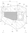
- FIG. 1 is a cross-sectional view showing a schematic configuration of a sealing structure according to a first embodiment of the present invention in a used state when applied to a pump.
- FIG. 2 is a perspective view of the sealing structure shown in FIG. 1 .
- FIG. 3 is a cross-sectional perspective view showing a portion of the sealing structure shown in FIG. 2 .
- 3 is a cross-sectional view of a support ring serving as an acting member in the sealing structure shown in FIG. 2.
- FIG. 13 is a perspective view showing a U-seal (U-packing) of a reference example.
- 1A is a vertical cross-sectional view showing a U-seal (U-packing) of a reference example, and FIG.
- FIG. 1B is a vertical cross-sectional view showing a cryogenic seal of an embodiment.
- 1A is a vertical cross-sectional view of a U-seal (U-packing) of a reference example, showing a state where the fluid to be sealed is at room temperature, and a state where the fluid to be sealed is at an extremely low temperature.
- FIG. 11 is a cross-sectional view showing a modified example of the sealing structure.
- FIG. 11 is a cross-sectional view showing a modified example of the sealing structure.
- FIG. 5 is a cross-sectional view showing a schematic configuration of a sealing structure according to a second embodiment of the present invention applied to a pump.
- FIG. 11 is a partially enlarged cross-sectional view of the sealing structure shown in FIG. 10 .
- FIG. 11 is an exploded perspective view of a sealing device of the sealing structure shown in FIG. 10 .
- 13 is a cross-sectional perspective view showing a portion of a seal ring in the sealing device shown in FIG. 12.
- 13 is a cross-sectional perspective view showing a portion of a pressure ring in the sealing device shown in FIG. 12.
- FIG. 4 is a cross-sectional view showing a cross section of the sealing structure in an assembled state of the pump.
- 11 is a diagram for comparing a seal ring when used at atmospheric temperature with a seal ring when used in a low-temperature environment.
- the sealing structure according to the embodiment of the present invention is a sealing structure for sealing an annular gap, and is applied to a pump that pumps liquid.
- the pump to which the sealing structure according to the embodiment of the present invention is applied is, for example, a pump that pumps low-temperature liquefied gas such as low-temperature liquid fuel for general industrial use.
- the low-temperature liquid fuel may be liquid hydrogen fuel.
- the sealing structure according to the embodiment of the present invention is used to seal an annular gap between a piston, which is a reciprocating member, and a cylinder having a cylindrical hole into which the piston is inserted.
- the application of the sealing structure according to the present invention is not limited to pumps that pump liquid.
- the sealing structure according to the present invention is applied to other pumps, other devices, mechanisms, structures, etc.
- a sealing structure 1 includes one sealing device 2.
- One sealing device 2 exhibits the desired sealing performance against fluids even in a low-temperature environment.
- One sealing device 2 has one seal ring 3 annular about the axis x, and one acting member 4 which is an annular member about the axis x.
- the acting member 4 is a member that acts on the seal ring 3, and acts so that the seal ring 3 exhibits the desired sealing performance in a low-temperature environment.
- the configuration of the sealing structure 1 will be specifically described below. Note that the axis x is the axis of the sealing structure 1.
- the seal ring 3 has a seal surface 5 facing the outer periphery that forms contact to seal the gap.
- the seal surface 5 is the surface of the seal ring 3 that contacts the member to which it is applied to in order to seal the gap when the sealing structure 1 is in use, as described below.
- the acting member 4 acts to maintain the contact of the seal surface 5 in a low-temperature environment. Specifically, the acting member 4 acts on the seal ring 3, which shrinks in a low-temperature environment, to maintain the contact of the seal surface 5.
- the acting member 4 supports the seal ring 3, for example, to maintain the contact of the seal surface 5. Also, the acting member 4 presses the seal ring 3 in one direction along the axis x (the direction of the arrow a in Figure 10) to maintain the contact of the seal surface 5.
- Fig. 1 is a cross-sectional view showing the schematic configuration of the sealing structure 10 according to the first embodiment of the present invention in a used state applied to a pump 100.
- Fig. 2 is an oblique view of the sealing structure 10 shown in Fig. 1
- Fig. 3 is a cross-sectional oblique view showing a part of the sealing structure 10 shown in Fig. 2
- Fig. 4 is a cross-sectional view of a support ring 31 as the acting member 4 in the sealing structure 10 shown in Fig. 2.
- Figs. 1, 3, and 4 show cross sections along a plane including the axis x.
- the sealing structure 10 includes a sealing device 11 as one sealing device 2, and the sealing device 11 includes a U-packing 21 as a seal ring 3 and a support ring 31 as an action member 4.
- the support ring 31 supports the U-packing 21 so as to maintain contact of the seal surfaces 5.
- the sealing structure 10 of this embodiment is attached to a pump 100 and is in a usable state.
- the sealing structure 10 is disposed, for example, between two members 101 arranged on the inner and outer periphery, and seals the gap between the two members 101, both of which are made of metal.
- the pump 100 is, for example, a boost pump, and the two members 101 are, for example, a cylinder 111 and a piston 121 of the pump.
- the cylinder 111 is an annular member that holds the piston 121 so that it can move back and forth freely, and constitutes the outer peripheral member of the two members 101.
- the inner peripheral surface 111a of the cylinder 111 is a cylindrical surface, and defines an internal space I into which the piston 121 is inserted.
- the inner peripheral surface 111a of the cylinder 111 is provided with an annular mounting groove 122 for accommodating the sealing structure 10.
- the piston 121 is housed in the internal space I of the cylinder 111 so that it can move back and forth freely, and is driven by a drive mechanism (not shown) to move back and forth within the internal space I of the cylinder 111.
- the boost pump boosts the liquid and pumps it to the outside.
- the liquid pumped by the pump 100 is, for example, a low-temperature liquid such as a low-temperature liquefied gas.
- the sealed structure 10 is placed in a low-temperature environment.
- a low-temperature environment is, for example, an environment in which the ambient temperature is lower than the atmospheric temperature.
- a low-temperature environment is an environment in which the ambient temperature is -253°C or an environment in which the ambient temperature is lower than -253°C.
- the sealing structure 10 When the sealing structure 10 is placed in a low-temperature environment, for example when the internal space I of the cylinder 111 is placed in a low-temperature environment of -253°C or lower, the sealing structure 10 that is housed in the mounting groove 122 and seals the gap between the piston 121 and the cylinder 111 must have the ability to seal liquid in a low-temperature environment.
- the sealing structure 10 of this embodiment which requires such performance, has a structure that combines a U-packing 21 and a support ring 31, as shown in Figures 1 to 3.
- the U-packing 21 is sized to fit into the mounting groove 122 of the cylinder 111, and has an annular shape around the axis x. As shown in Figs. 1 and 3, the U-packing 21 has a U-shape.
- the U-packing 21 has a base 22 on one end E1 side in the axis x direction, and a lip portion 23 on the end E2 side opposite the base 22.
- the base 22 is an annular portion around the axis x.
- the U-packing 21 also has an annular inner lip 24 and an outer lip 25 that branch off from the base 22 toward the end E2 side in the axis x direction.
- the outer lip 25 is provided on the outer periphery side of the inner lip 24.
- the base 22 is a region on the root side that is not branched into a U-shape, and as shown in Figures 1 and 3, the cross section of the base 22 when cut along a plane including the axis x is rectangular. More specifically, the cross-sectional shape of the base 22 is a rectangular shape with both shoulders chamfered at the end E1.
- the lip portion 23 has a shape that branches out from both the inner and outer periphery of the base portion 22 and extends toward the end portion E2. As described above, of the regions that branch out and extend from the base portion 22, the inner lip 24 is located on the inner periphery side, and the outer lip 25 is located on the outer periphery side. As a result of the lip portion 23 branching into the inner lip 24 and the outer lip 25 in this way, the inner lip 24 and the outer lip 25 form an annular space S that is recessed toward the end portion E1 in the direction of the axis x, and a concave space S is provided between the inner lip 24 and the outer lip 25, giving the U-packing 21 a U-shaped cross-sectional shape.
- the inner side is the side toward the axis x in the direction perpendicular to the axis x (also called the radial direction).
- the outer side is the side away from the axis x in the direction perpendicular to the axis x.
- the inner lip 24 extends at an angle inward beyond the inner sidewall 22a of the base 22, with the lip piece 24a protruding inward from the sidewall 22a.
- the end of the lip piece 24a on the inner diameter side has an inverse tapered shape that expands in diameter toward the end E2 of the U-packing 21, giving the part with the smallest inner diameter a pointed cross-sectional shape that forms the apex of a triangle. This pointed part is the lip end 24b.
- the lip end 24b is the inner sealing surface that contacts the outer circumferential surface 121a of the piston 121.
- the outer peripheral lip 25 extends at an angle toward the outer periphery beyond the outer peripheral sidewall 22b of the base 22, with a lip piece 25a protruding from the sidewall 22b toward the outer periphery.
- the outer peripheral surface of the outer peripheral lip 25 is given, for example, a curved cross-sectional shape. This curved portion is the lip end 25b.
- the lip end 25b is the seal surface 5 that faces the outer periphery and comes into contact with the cylinder 111 to seal the gap between the piston 121 and the cylinder 111.
- the space S is defined by the bottom surface S1, which is the inner wall of the base 22, the inner wall surface S2, which is the inner wall of the inner lip 24, and the outer wall surface S3, which is the inner wall of the outer lip 25, and has an opening S4 that opens to the end E2 of the U-packing 21.
- the inner lip 24 and the outer lip 25 are formed relatively thin, so that the bottom surface S1 has a relatively large area.
- the inner wall surface S2 and the outer wall surface S3 of the space S have an inclined shape that increases the distance between them toward the opening S4.
- the inner surface of the inner lip 24, which forms the inner wall surface S2 has an inclined shape that reduces in diameter toward the tip
- the inner surface of the outer lip 25, which forms the outer wall surface S3, has an inclined shape that increases in diameter toward the tip.
- the U-packing 21 is entirely made of a fluororesin material such as PTFE, giving it a certain degree of hardness and elasticity.
- the support ring 31 is an annular member that is disposed in the concave space S between the inner lip 24 and the outer lip 25, and contacts and supports the outer wall surface S3, which is the inner wall of the outer lip 25.
- a support ring 31 is made of a rigid body such as metal so that it can suppress the reduction in diameter of the outer lip 25, even when the fluororesin material from which the U-packing 21 is made shrinks when placed in a low-temperature environment, for example.
- the support ring 31 is a rigid body, no matter what material is used and what form the support ring 31 is provided in, since it is a real material, the support ring 31 cannot be realized as a theoretically perfect rigid body.
- the rigid body means a member having a rigidity of at least a degree capable of restricting the reduction in diameter of the inner wall (outer wall surface S3) of the outer lip 25 so that the lip end 25b (seal surface 5) of the outer lip 25 does not separate from the bottom 122a of the mounting groove 122 even if the U-packing 21 shrinks when the sealing structure 10 is placed in a low-temperature environment, that is, so that contact between the lip end 25b (seal surface 5) and the bottom 122a of the mounting groove 122 is maintained.
- the shape, material, and other forms of the support ring 31 may be elastic as long as they support the outer lip 25 so that contact between the lip end 25b (seal surface 5) and the bottom 122a of the mounting groove 122 is maintained.
- a pipe-shaped support ring 31 is used, in which the cross section of the support ring 31 taken along a plane perpendicular to the extension direction of the support ring 31 around the axis x is C-shaped.
- Each part of the support ring 31 is in contact with the bottom surface S1 and the outer peripheral wall surface S3 of the space S, but not with the inner peripheral wall surface S2, and is sized so that it is completely contained within the space S without protruding from the opening S4.
- FIG 5 is a perspective view showing a U-seal 201 of the Reference Example.
- the U-seal 201 of the Reference Example does not have a support ring 31 and is composed only of a U-packing. Therefore, as shown in Figure 6(A), the U-seal 201 is similar to the configuration of the sealing structure 10 of the present embodiment shown in Figure 6(B) which is composed only of the U-packing 21. However, what differs from the U-packing 21 of the present embodiment is the thickness of the outer peripheral lip 202 (outer peripheral lip 25 in this embodiment).
- the U-seal 201 which is made of a fluororesin material such as PTFE, contracts. This narrows the gap G1 between the U-seal 201 and the outer circumferential surface of the piston 121, and expands the gap G2 between the U-seal 201 and the bottom 122a of the mounting groove 122. As a result, as shown in the area enclosed by the dashed line in FIG.
- the lip end 202a (sealing surface) of the outer circumferential lip 202 moves away from the bottom 122a of the mounting groove 122, and the gap G2 exceeds the gap between the lip end 202a and the bottom 122a.
- the airtightness of the internal space I of the cylinder 111 decreases, causing a decrease in the pressurizing pressure and fluid leakage.
- the U-packing 21 molded from a fluororesin material such as PTFE contracts, just like the U-seal 201 of the reference example.
- the gap G1 between the inner peripheral side wall 22a and the outer peripheral surface of the piston 121 also narrows, just like the U-seal 201 of the reference example.
- the support ring 31 acts on the outer lip 25's diameter reduction movement, and the support ring 31 exerts a regulating force. More specifically, even if the outer wall surface S3, which is the inner wall of the outer lip 25, tries to move in the diameter reduction direction, the support ring 31 regulates the movement by blocking it. Therefore, the significant diameter reduction that occurs in the outer lip 202 of the reference example does not occur in the outer lip 25 of this embodiment, and the bottom 122a of the mounting groove 122 and the lip end 25b (seal surface 5) of the outer lip 25 can be maintained in contact. As a result, the airtightness of the internal space I of the cylinder 111 can be maintained, making it possible to avoid a decrease in the boost pressure and fluid leakage.
- the thickness T1 of the outer peripheral lip 25 in this embodiment is approximately half the thickness T2 of the outer peripheral lip 202 in the reference example, so the force generated when the outer peripheral lip 25 contracts is reduced. This makes it possible to prevent the application of a large force that would cause deformation to the support ring 31.
- the sealing structure 10 according to this embodiment can maintain sealing performance against fluids or suppress deterioration of sealing performance with a single sealing device 11 even in a low-temperature environment. Therefore, the sealing structure 10 according to this embodiment can achieve the desired sealing performance with a single sealing device 11 even in a low-temperature environment.
- This desired sealing performance is, for example, a sealing performance that is arbitrarily set by a user or the like depending on the application target and application situation of the sealing structure 10. Specifically, for example, the desired sealing performance is set by setting the amount of leakage from the sealed target for a specified usage time under specified usage conditions such as a specified temperature and atmospheric pressure.
- the sealing structure 10 can maintain sealing performance or suppress deterioration of sealing performance even in low temperature environments with a simple structure of a single sealing device, rather than sealing by arranging multiple sealing devices in series and providing multiple tiers of blocking structures as in the conventional method. Therefore, with the sealing structure 10 according to the embodiment of the present invention, it is possible to obtain the desired sealing performance against fluids with a simple structure, even in low temperature environments.
- FIGS. 8 and 9 are cross-sectional views showing a modified example of the sealing structure 10.
- the same parts as those in the above-mentioned embodiment described with reference to Figs. 1 to 7 are indicated by the same reference numerals, and the description thereof will be omitted.
- This modified example is an example in which a rigid metal O-ring member is used as the support ring 31.
- the fact that the O-ring member is rigid, the significance of the rigidity, the dimensional relationship with the U-packing 21, the mounting position with respect to the U-packing 21, etc. are the same as in the above embodiment.
- the support ring 31 is placed in the concave space S between the inner lip 24 and the outer lip 25, and is an annular rigid body that supports the inner wall of the outer lip 25. It is not limited to a metal pipe-shaped member with a C-shaped cross section (see Figure 4) or a metal O-ring member (Figure 9), and any other type of member can be used.
- the support ring 31 does not have to be sized to be completely contained within the space S without contacting the bottom surface S1 of the space S but not contacting the inner wall surface S2, as in the above embodiment, and without protruding from the opening S4.
- a support ring 31 that contacts three surfaces, the bottom surface S1, the inner wall surface S2, and the outer wall surface S3, may be used, or a support ring 31 that contacts two surfaces, the inner wall surface S2 and the outer wall surface S3, but not the bottom surface S1 may be used.
- sealing structure 12 as the sealing structure 1 according to the second embodiment of the present invention.
- FIG. 10 is a cross-sectional view showing a schematic configuration of a sealing structure 12 according to a second embodiment of the present invention in a state of use applied to a pump 150
- FIG. 11 is a partially enlarged cross-sectional view of the sealing structure 12 shown in FIG. 10.
- FIG. 10 shows a cross section along a plane including the axis x.
- the sealing structure 12 according to the second embodiment includes a sealing device 13 as one sealing device 2, and the sealing device 13 includes a seal ring 41 as a seal ring 3 and a pressure ring 51 as an action member 4.
- the sealing structure 12 also has an action surface 62 acting on the seal ring 41.
- the action surface 62 is configured to press the seal ring 41 pressed by the pressure ring 51 in a direction that forms contact of the seal surfaces 5.
- the pressure ring 51 presses the seal ring 41 in one direction of the axis x (the direction of the arrow a in FIGS. 10 and 11) so as to maintain contact of the seal surfaces 5.
- the pressure ring 51 presses the seal ring 41 in one direction along the axis x, so that the contact of the seal surface 5 is maintained in a low-temperature environment.
- the configuration of the sealing structure 12 will be described in detail below.
- the pressure ring 51 presses the seal ring 41 in one direction along the axis x so that the action surface 62 presses the seal ring 41 in a direction that forms contact with the seal surface 5, thereby maintaining contact of the seal surface 5 of the seal ring 41.
- the sealing structure 12 has an accommodation groove 61 that is an annular groove around the axis x that accommodates the sealing device 13.
- the accommodation groove 61 is open to the outer periphery, and has an action surface 62 that is an annular surface around the axis x.
- the accommodation groove 61 is formed on the outer peripheral surface 152a of the piston 152 of the pump 150 to which the sealing structure 12 is applied.
- the accommodation groove 61 is an annular groove recessed from the outer peripheral surface 152a of the piston 152 to the inner peripheral side.
- the accommodation groove 61 has wall surfaces 63, 64 which are annular surfaces facing each other in the direction of the axis x, and an action surface 62 and a bottom surface 65 extend between the wall surfaces 63 and 64.
- the bottom surface 65 is a cylindrical surface extending along the axis x and is located on the innermost side of the accommodation groove 61.
- the action surface 61 extends from the inner peripheral end of the wall surface 63 to the wall surface 64 side, and the bottom surface 65 extends from the wall surface 64 side end of the action surface 62 to the inner peripheral end of the wall surface 64.
- the action surface 62 is a tapered surface that expands in diameter from the wall surface 64 side to the wall surface 63 side (to one side of the axis x direction (the direction of arrow a)).
- the action surface 62 is, for example, a surface that expands in diameter smoothly.
- the action surface 62 may be a tapered surface that expands in diameter continuously from the wall surface 64 side to the wall surface 63 side, or a tapered surface that expands in diameter discontinuously from the wall surface 64 side to the wall surface 63 side.
- a surface that expands in diameter discontinuously is, for example, a surface that combines an expanding cylindrical surface and a cylindrical surface with a constant diameter.
- the action surface 62 is, for example, a conical surface or an approximately conical surface with the axis x as the central axis or approximately the central axis.
- the pump 150 has two members 151, a piston 152 and a cylinder 153, similar to the pump 100 described above. Both the piston 152 and the cylinder 153 are made of metal. An annular gap is formed between the two members 151.
- the cylinder 153 is, for example, an annular member that holds the piston 152 so that it can reciprocate, and constitutes the outer peripheral member of the two members 151.
- the inner peripheral surface 153a of the cylinder 153 is a cylindrical surface, and defines an internal space I into which the piston 152 is inserted.
- the piston 152 is stored in the internal space I of the cylinder 153 so that it can reciprocate, and is driven by a drive mechanism (not shown) to reciprocate in the internal space I of the cylinder 153.
- the sealing structure 12 is applied to the pump 150 and is in a usable state. The sealing structure 12 seals the gap between the two members 151.
- the pump 150 is, for example, a boost pump, which boosts the pressure of the liquid and pumps it to the outside.
- the liquid pumped by the pump 150 is, for example, a low-temperature liquid such as a low-temperature liquefied gas.
- the sealing structure 12 is placed in a low-temperature environment.
- a low-temperature environment is, for example, an environment in which the ambient temperature is lower than the atmospheric temperature.
- a low-temperature environment is an environment in which the ambient temperature is -253°C, or an environment in which the ambient temperature is lower than -253°C.
- FIG. 12 is an exploded perspective view of the sealing device 13 of the sealing structure 12.
- FIG. 13 is a cross-sectional perspective view showing a portion of the seal ring 41 in the sealing device 13
- FIG. 14 is a cross-sectional perspective view showing a portion of the pressure ring 51 of the sealing device 13. Note that FIGS. 13 and 14 show cross sections taken along a plane including the axis x.
- the seal ring 41 is pushed in one direction in the axial x direction in the accommodation groove 61, and is pushed in the direction of forming contact of the seal surface 5, that is, against the inner peripheral surface 153a of the cylinder 153, by the action of the acting surface 62.
- the seal ring 41 has the acted surface 42, which is an annular surface that contacts the acting surface 62.
- the acted surface 42 has a shape corresponding to the acting surface 62.
- the acting surface 42 is a tapered surface that expands in diameter toward one side of the axial x direction (the direction of the arrow a).
- the acted surface 42 is, for example, arranged to contact the acting surface 62 over the entirety or substantially the entirety, and has the same or substantially the same shape as the acting surface 62.
- the acted surface 42 is, for example, a surface that expands in diameter smoothly.
- the acted surface 42 may be a tapered surface that continuously expands in diameter toward one side in the direction of the axis x, or may be a tapered surface that intermittently expands in diameter toward one side in the direction of the axis x.
- an intermittently expanding surface is, for example, a surface that combines an expanding cylindrical surface with a cylindrical surface of a constant diameter.
- the acted surface 42 is, for example, a conical surface or an approximately conical surface with the axis x as the central axis or approximately the central axis.
- the seal ring 41 has an outer peripheral surface 43 that faces the outer peripheral side and is an annular surface around the axis x facing away from the acted surface 42.
- the outer peripheral surface 43 is adapted to contact the inner peripheral surface 153a of the cylinder 153 over the entire circumference, and the outer peripheral surface 43 serves as the seal surface 5.
- the outer peripheral surface 43 is, for example, a cylindrical surface or an approximately cylindrical surface with the axis x as the central axis or approximately central axis.
- the width of the outer peripheral surface 43 in the axial direction is greater than the width of the acted surface 42 in the axial direction. Also, as shown in Fig.
- the position of the end (end 43a) on one side of the outer peripheral surface 43 in the axial direction is the same or approximately the same as the position of the end (end 42a) on one side of the acted surface 42 in the axial direction. Also, as shown in FIG. 11, the position of the end (end 43b) of the outer peripheral surface 43 on the other side in the axial x direction is different from the position of the end (end 42b) of the acted surface 42 on the other side in the axial x direction, and is located on the other side (arrow b direction) of the axial x direction than the end 42b.
- the width of the outer peripheral surface 43 (seal surface 5) in the axial x direction may be the same as the width of the acted surface 42 in the axial x direction, or may be smaller than the width of the acted surface 42 in the axial x direction.
- the position of the end 43a of the outer peripheral surface 43 in the axial x direction may be different from the position of the end 42a of the acted surface 42 in the axial x direction.
- the position of the end 43b of the outer peripheral surface 43 in the axial x direction may be the same as the position of the end 42b of the acted surface 42 in the axial x direction, or may be located on one side of the end 42b in the axial x direction.
- the seal ring 41 is pressed in one direction along the axis x by the pressure ring 51 in the accommodation groove 61.
- the seal ring 41 has an acted surface 44, which is an annular surface with which the pressure ring 51 comes into contact in the accommodation groove 61.
- the acted surface 44 of the seal ring 41 is provided on the other side of the axis x direction from the outer circumferential surface 43 (seal surface 5) and the acted surface 42, and is an annular surface facing the other side of the axis x direction (arrow b direction).
- Figs. 10 to 13 the acted surface 44 of the seal ring 41 is provided on the other side of the axis x direction from the outer circumferential surface 43 (seal surface 5) and the acted surface 42, and is an annular surface facing the other side of the axis x direction (arrow b direction).
- the acted surface 44 is a surface that is parallel or approximately parallel to a plane perpendicular to the axis x.
- the acted surface 44 may be inclined with respect to a plane perpendicular to the axis x.
- the acted surface 44 may also be a surface that is not a flat surface, such as a curved surface.
- the seal ring 41 has a side surface 45, which is an annular surface facing one side in the direction of the axis x, arranged opposite the acted surface 44, and a bottom surface 46, which is a cylindrical surface facing the inner periphery and extends between the acted surface 42 and the acted surface 44. Note that the seal ring 41 does not have to have a bottom surface 46. In this case, the acted surface 42 is connected to the acted surface 44.
- the radial width of the seal ring 41 is such that, in the usage state, the outer peripheral surface 43 (seal surface 5) contacts the inner peripheral surface 153a of the cylinder 153, and the acted surface 42 contacts the acting surface 62 of the accommodation groove 61 of the piston 152.
- the radial width of the seal ring 41 is such that, in the usage state, the bottom surface 46 does not contact the bottom surface 65 of the accommodation groove 61 of the piston 152.
- the width of the seal ring 41 in the axial x direction is such that, in the usage state, the side surface 45 does not contact the side wall 63 of the accommodation groove 61, and the acted surface 44 does not contact the side wall 64 of the accommodation groove 61.
- the usage state also includes the ambient temperature used. In other words, when the sealing structure 12 is used in a low-temperature environment, the usage state is a low-temperature environment state.
- the seal ring 41 is made of, for example, a resin.
- the resin material forming the seal ring 41 include resin materials such as polyether ether ketone (PEEK), polyphenylene sulfide (PPS), polytetrafluoroethylene (PTFE), polyimide (PI), and polyamideimide (PAI).
- the resin material of the seal ring 41 may include, for example, a filler for improving sliding characteristics and strength.
- the seal ring 41 is used in a pump for pumping liquid.
- the material of the seal ring 41 is preferably a material with a small linear expansion coefficient.
- the material of the seal ring 41 is a material with a linear expansion coefficient smaller than 15 ⁇ 10 ⁇ 5 /° C.
- the resin material of the seal ring 41 is preferably PEEK, which has a small linear expansion coefficient.
- the pressing ring 51 presses the seal ring 41 in one direction along the axis x in the accommodation groove 61.
- the pressing ring 51 generates an elastic force in the accommodation groove 61 in a direction along the axis x, and is, for example, an elastic member that generates an elastic force in a direction along the axis x.
- the pressing ring 51 is compressed in the direction of the axis x, for example, between the side wall 64 of the accommodation groove 61 and the acting surface 44 of the seal ring 41.
- the pressing ring 51 has a cross-sectional shape in a plane including the axis x that is arc-shaped, approximately arc-shaped, or C-shaped, and an annular gap 52 that is open to the outer periphery in the radial direction is formed.
- the width of the pressing ring 51 in the direction of the axis x is larger than the width in the direction of the axis x between the side wall 64 of the accommodation groove 61 and the acting surface 44 of the seal ring 41 in the use state.
- the pressure ring 51 is adapted to come into contact with, for example, the bottom surface 65 of the storage groove 61.
- the pressure ring 51 is made of, for example, metal, and the linear expansion coefficient of the pressure ring 51 is smaller than the linear expansion coefficient of the seal ring 41.
- the shape of the pressure ring 51 is not limited to the above-mentioned shape, and may be any other shape as long as it can press the seal ring 41 in one direction along the axis x when in use.
- the cross-sectional shape of the pressure ring 51 may be annular, circular, or approximately circular.
- the pressure ring 51 may be a spring member, a coil member, a metal O-ring, or other member as long as it can press the seal ring 41 in one direction along the axis x when in use.
- Figure 15 is a cross-sectional view showing the sealing structure 12 when the pump 150 is assembled. Since the pump 150 is normally assembled at ambient temperature, the sealing structure 12 when the pump 150 is assembled is in a state where the ambient temperature is ambient temperature. In other words, Figure 15 shows the sealing structure 12 in use when the ambient temperature is ambient temperature.
- the outer peripheral surface 43 (seal surface 5) of the seal ring 41 is in contact with the inner peripheral surface 153a of the cylinder 153, and the acted surface 42 is in contact with the acting surface 62 of the accommodating groove 61 of the piston 152.
- the pressure ring 51 is sandwiched between the acted surface 44 of the seal ring 41 and the side wall 64 of the accommodating groove 61 and is compressed in the direction of the axis x.
- the pressure ring 51 acts on the acted surface 44, and the seal ring 41 is pressed in one direction in the direction of the axis x by the pressure ring 51.
- this pressure ring 51 By the action of this pressure ring 51, the acted surface 42 of the seal ring 41 is pressed against the acting surface 62 of the accommodating groove 61. Therefore, the acted surface 42 of the seal ring 41 receives a reaction force from the acting surface 62 of the accommodation groove 61, and is pressed against the inner circumferential surface 153a of the cylinder 153 by the radial component of the reaction force. In this way, the seal ring 41 seals the gap between the piston 152 and the cylinder 153. In other words, it seals the liquid that is pressurized in the internal space I of the cylinder 153.
- the distance from the side wall 63 of the accommodation groove 61 to the side surface 45 of the seal ring 41 in the axial x direction is distance Da1. Also, the distance from the side wall 63 of the accommodation groove 61 to the acted surface 44 of the seal ring 41 in the axial x direction is distance Db1.
- the seal ring 41 shrinks, and the radial width of the seal ring 41 becomes smaller than the radial width of the seal ring 41 in the assembled state of the pump 150 shown in FIG. 15. In this way, the seal ring 41 shrinks in a direction in which the outer circumferential surface 43 (seal surface 5) moves away from the inner circumferential surface 153a of the cylinder 153, and in a direction in which the acted surface 42 moves away from the acting surface 62 of the accommodation groove 61.
- FIG. 16 is a diagram for comparing the seal ring 41 when used at ambient temperature with the seal ring 41 when used in a low-temperature environment.
- the seal ring 41 shrinks and the distance in the axial x direction from the side wall 63 of the accommodation groove 61 to the side surface 45 of the seal ring 41 is distance Da2. Also, the distance in the axial x direction from the side wall 63 of the accommodation groove 61 to the acted surface 44 of the seal ring 41 is distance Db2. Thus, the distance Da2 in the axial x direction from the side wall 63 to the side surface 45 when used in a low-temperature environment is shorter than the distance Da1 in the axial x direction from the side wall 63 to the side surface 45 when used in a state where the ambient temperature is atmospheric temperature (Da2 ⁇ Da1).
- the distance Db2 in the axial x direction from the side wall 63 to the acted surface 44 when used in a low-temperature environment is shorter than the distance Db1 in the axial x direction from the side wall 63 to the acted surface 44 when used in a state where the ambient temperature is atmospheric temperature (Db2 ⁇ Db1). Furthermore, when used in a low-temperature environment, the pressure ring 51 expands in the direction of the axis x, but is compressed in the direction of the axis x between the acted surface 44 and the side wall 64, and the pressure ring 51 presses the shrinking seal ring 41 in one direction in the direction of the axis x.
- the seal ring 41 acts in the same way as when the ambient temperature is atmospheric temperature, and the acted surface 42 of the seal ring 41 is pressed against the acting surface 62 of the accommodation groove 61, and the outer peripheral surface 43 (seal surface 5) of the seal ring 41 is pressed against the inner peripheral surface 153a of the cylinder 153 by this reaction force.
- the seal ring 41 seals the gap between the piston 152 and the cylinder 153 even when used in a low-temperature environment, that is, it seals the liquid that is pressurized in the internal space I of the cylinder 153 even when used in a low-temperature environment.
- the seal ring 41 seals the gap between the piston 152 and the cylinder 153, and seals the liquid that is pressurized in the internal space I of the cylinder 153.
- the shape of the pressure ring 51 is set so that the pressure ring 51 acts on the acted surface 44 of the seal ring 41 even when used in a low-temperature environment.
- the compression width of the pressure ring 51 in the axial x direction in a usage state where the ambient temperature is atmospheric temperature is set so that the pressure ring 51 acts on the acted surface 44 of the seal ring 41 even when used in a low-temperature environment.
- the properties of the pressure ring 51 such as the elastic coefficient, are set so that the pressure ring 51 acts on the acted surface 44 of the seal ring 41 even when used in a low-temperature environment.
- the sealing structure 12 according to this embodiment can maintain sealing performance against fluids or suppress deterioration of sealing performance even in low-temperature environments with a single sealing device 13. Therefore, the sealing structure 12 according to this embodiment can achieve the desired sealing performance with a single sealing device 13 even in low-temperature environments.
- This desired sealing performance is, for example, a sealing performance that is arbitrarily set by a user or the like depending on the application target and application situation of the sealing structure 12. Specifically, for example, the desired sealing performance is set by setting the amount of leakage from the sealed target for a specified usage time under specified usage conditions such as a specified temperature and atmospheric pressure.
- the sealing structure 12 does not seal by arranging multiple sealing devices in series and providing multiple closure structures in stages, as in the conventional method, but rather has a simple structure of a single sealing device that can maintain sealing performance or suppress deterioration of sealing performance even in low-temperature environments. Therefore, with the sealing structure 12 according to the embodiment of the present invention, it is possible to obtain the desired sealing performance against fluids with a simple structure, even in low-temperature environments.
- the above-described embodiments are intended to facilitate understanding of the present invention, and are not intended to limit the present invention. Furthermore, the above-described embodiments do not limit the applications for which the present invention is used, and the present invention can include anything as its application.
- the components of the above-described embodiments, as well as their arrangement, materials, conditions, shapes, sizes, etc., are not limited to those exemplified, and can be modified as appropriate.
- the present invention includes differences that arise in implementation due to manufacturing tolerances, etc.
- the components shown in different embodiments can be partially substituted or combined to the extent that there is no technical contradiction.
- the configurations can be selectively combined as appropriate to achieve at least some of the above-described problems and effects.
- the seal ring 3 (U-packing 21, seal ring 41) is not limited to an endless annular shape, and may be provided with a cut portion having a pair of ends that are in liquid-tight contact with each other.
- the cut portion forms, for example, a joint, and the joint may be, for example, a joint with a well-known special step cut shape, a joint with a step cut shape, a joint with a straight cut shape, or a joint with a bias cut shape.
- the action member 4 (support ring 31, pressure ring 51) is not limited to an endless annular shape, and may be provided with a cut portion having a pair of ends.
- the action member 4 (support ring 31, pressure ring 51) may extend in an annular shape intermittently.
Landscapes
- Engineering & Computer Science (AREA)
- General Engineering & Computer Science (AREA)
- Mechanical Engineering (AREA)
- Gasket Seals (AREA)
- Sealing Devices (AREA)
Priority Applications (4)
| Application Number | Priority Date | Filing Date | Title |
|---|---|---|---|
| JP2025506479A JPWO2024190005A1 (https=) | 2023-03-10 | 2023-12-05 | |
| KR1020257029523A KR20250143823A (ko) | 2023-03-10 | 2023-12-05 | 밀봉 구조 |
| CN202380095501.XA CN121079526A (zh) | 2023-03-10 | 2023-12-05 | 密封结构 |
| EP23927610.8A EP4678954A1 (en) | 2023-03-10 | 2023-12-05 | Sealing structure |
Applications Claiming Priority (2)
| Application Number | Priority Date | Filing Date | Title |
|---|---|---|---|
| JP2023037317 | 2023-03-10 | ||
| JP2023-037317 | 2023-03-10 |
Publications (1)
| Publication Number | Publication Date |
|---|---|
| WO2024190005A1 true WO2024190005A1 (ja) | 2024-09-19 |
Family
ID=92754714
Family Applications (1)
| Application Number | Title | Priority Date | Filing Date |
|---|---|---|---|
| PCT/JP2023/043541 Ceased WO2024190005A1 (ja) | 2023-03-10 | 2023-12-05 | 密封構造 |
Country Status (5)
| Country | Link |
|---|---|
| EP (1) | EP4678954A1 (https=) |
| JP (1) | JPWO2024190005A1 (https=) |
| KR (1) | KR20250143823A (https=) |
| CN (1) | CN121079526A (https=) |
| WO (1) | WO2024190005A1 (https=) |
Citations (6)
| Publication number | Priority date | Publication date | Assignee | Title |
|---|---|---|---|---|
| JPS6232265U (https=) * | 1985-08-13 | 1987-02-26 | ||
| JPH04191571A (ja) * | 1990-11-26 | 1992-07-09 | Mitsubishi Cable Ind Ltd | 低温用シール |
| JP2016014481A (ja) | 2014-06-12 | 2016-01-28 | 三菱電線工業株式会社 | シールリング |
| JP2022074182A (ja) * | 2020-11-03 | 2022-05-18 | 株式会社豊田自動織機 | オイルシール |
| CN217002848U (zh) * | 2021-12-08 | 2022-07-19 | 无锡恩福油封有限公司 | 密封装置 |
| CN217539444U (zh) * | 2021-12-08 | 2022-10-04 | 无锡恩福油封有限公司 | 密封装置及密封结构 |
-
2023
- 2023-12-05 JP JP2025506479A patent/JPWO2024190005A1/ja active Pending
- 2023-12-05 EP EP23927610.8A patent/EP4678954A1/en active Pending
- 2023-12-05 CN CN202380095501.XA patent/CN121079526A/zh active Pending
- 2023-12-05 KR KR1020257029523A patent/KR20250143823A/ko active Pending
- 2023-12-05 WO PCT/JP2023/043541 patent/WO2024190005A1/ja not_active Ceased
Patent Citations (6)
| Publication number | Priority date | Publication date | Assignee | Title |
|---|---|---|---|---|
| JPS6232265U (https=) * | 1985-08-13 | 1987-02-26 | ||
| JPH04191571A (ja) * | 1990-11-26 | 1992-07-09 | Mitsubishi Cable Ind Ltd | 低温用シール |
| JP2016014481A (ja) | 2014-06-12 | 2016-01-28 | 三菱電線工業株式会社 | シールリング |
| JP2022074182A (ja) * | 2020-11-03 | 2022-05-18 | 株式会社豊田自動織機 | オイルシール |
| CN217002848U (zh) * | 2021-12-08 | 2022-07-19 | 无锡恩福油封有限公司 | 密封装置 |
| CN217539444U (zh) * | 2021-12-08 | 2022-10-04 | 无锡恩福油封有限公司 | 密封装置及密封结构 |
Non-Patent Citations (1)
| Title |
|---|
| See also references of EP4678954A1 |
Also Published As
| Publication number | Publication date |
|---|---|
| JPWO2024190005A1 (https=) | 2024-09-19 |
| CN121079526A (zh) | 2025-12-05 |
| EP4678954A1 (en) | 2026-01-14 |
| KR20250143823A (ko) | 2025-10-02 |
Similar Documents
| Publication | Publication Date | Title |
|---|---|---|
| US8328202B2 (en) | Seal assembly for high pressure dynamic and static services | |
| US20080018059A1 (en) | Sealing Device | |
| US7032905B2 (en) | Leak resistant seal | |
| US12281709B2 (en) | Piston ring and booster pump | |
| WO2024190005A1 (ja) | 密封構造 | |
| EP1832787A1 (en) | Sealing device | |
| CN110520658B (zh) | 密封件的配置构造 | |
| JP5531386B2 (ja) | シーリングシステム | |
| JP5897693B2 (ja) | 軸密封構造 | |
| JP6566040B2 (ja) | シールリング | |
| JP2017133571A (ja) | 密封装置 | |
| EA037324B1 (ru) | Диафрагма с уплотнением кромки | |
| JP5211927B2 (ja) | 密封装置 | |
| JP2005036827A (ja) | 封止リング | |
| KR20260056221A (ko) | 밀봉 장치 | |
| WO2025069730A1 (ja) | 密封装置 | |
| JP6458905B2 (ja) | シールリング | |
| JP7773007B1 (ja) | シールリング | |
| JP6677009B2 (ja) | 密封構造 | |
| JP2015140861A (ja) | 密封装置 | |
| JP2018159386A (ja) | 密封装置 | |
| JP6440154B1 (ja) | ロッドパッキン | |
| JP2025140732A (ja) | ロッドパッキン | |
| JP2017155771A (ja) | 密封装置及び密封構造 | |
| JP6623775B2 (ja) | 密封構造 |
Legal Events
| Date | Code | Title | Description |
|---|---|---|---|
| 121 | Ep: the epo has been informed by wipo that ep was designated in this application |
Ref document number: 23927610 Country of ref document: EP Kind code of ref document: A1 |
|
| ENP | Entry into the national phase |
Ref document number: 1020257029523 Country of ref document: KR Free format text: ST27 STATUS EVENT CODE: A-0-1-A10-A15-NAP-PA0105 (AS PROVIDED BY THE NATIONAL OFFICE) |
|
| ENP | Entry into the national phase |
Ref document number: 2025506479 Country of ref document: JP Kind code of ref document: A |
|
| WWE | Wipo information: entry into national phase |
Ref document number: 2025506479 Country of ref document: JP |
|
| WWP | Wipo information: published in national office |
Ref document number: 1020257029523 Country of ref document: KR |
|
| WWE | Wipo information: entry into national phase |
Ref document number: 2023927610 Country of ref document: EP |
|
| NENP | Non-entry into the national phase |
Ref country code: DE |
|
| ENP | Entry into the national phase |
Ref document number: 2023927610 Country of ref document: EP Effective date: 20251010 |
|
| ENP | Entry into the national phase |
Ref document number: 2023927610 Country of ref document: EP Effective date: 20251010 |
|
| ENP | Entry into the national phase |
Ref document number: 2023927610 Country of ref document: EP Effective date: 20251010 |
|
| ENP | Entry into the national phase |
Ref document number: 2023927610 Country of ref document: EP Effective date: 20251010 |
|
| WWP | Wipo information: published in national office |
Ref document number: 2023927610 Country of ref document: EP |