WO2024189751A1 - 運搬車両 - Google Patents
運搬車両 Download PDFInfo
- Publication number
- WO2024189751A1 WO2024189751A1 PCT/JP2023/009711 JP2023009711W WO2024189751A1 WO 2024189751 A1 WO2024189751 A1 WO 2024189751A1 JP 2023009711 W JP2023009711 W JP 2023009711W WO 2024189751 A1 WO2024189751 A1 WO 2024189751A1
- Authority
- WO
- WIPO (PCT)
- Prior art keywords
- power
- generator
- exhaust gas
- additional
- controller
- Prior art date
- Legal status (The legal status is an assumption and is not a legal conclusion. Google has not performed a legal analysis and makes no representation as to the accuracy of the status listed.)
- Pending
Links
Images


Classifications
-
- B—PERFORMING OPERATIONS; TRANSPORTING
- B60—VEHICLES IN GENERAL
- B60W—CONJOINT CONTROL OF VEHICLE SUB-UNITS OF DIFFERENT TYPE OR DIFFERENT FUNCTION; CONTROL SYSTEMS SPECIALLY ADAPTED FOR HYBRID VEHICLES; ROAD VEHICLE DRIVE CONTROL SYSTEMS FOR PURPOSES NOT RELATED TO THE CONTROL OF A PARTICULAR SUB-UNIT
- B60W20/00—Control systems specially adapted for hybrid vehicles
- B60W20/10—Controlling the power contribution of each of the prime movers to meet required power demand
- B60W20/15—Control strategies specially adapted for achieving a particular effect
- B60W20/16—Control strategies specially adapted for achieving a particular effect for reducing engine exhaust emissions
-
- F—MECHANICAL ENGINEERING; LIGHTING; HEATING; WEAPONS; BLASTING
- F01—MACHINES OR ENGINES IN GENERAL; ENGINE PLANTS IN GENERAL; STEAM ENGINES
- F01N—GAS-FLOW SILENCERS OR EXHAUST APPARATUS FOR MACHINES OR ENGINES IN GENERAL; GAS-FLOW SILENCERS OR EXHAUST APPARATUS FOR INTERNAL-COMBUSTION ENGINES
- F01N3/00—Exhaust or silencing apparatus having means for purifying, rendering innocuous, or otherwise treating exhaust
- F01N3/08—Exhaust or silencing apparatus having means for purifying, rendering innocuous, or otherwise treating exhaust for rendering innocuous
- F01N3/10—Exhaust or silencing apparatus having means for purifying, rendering innocuous, or otherwise treating exhaust for rendering innocuous by thermal or catalytic conversion of noxious components of exhaust
- F01N3/18—Exhaust or silencing apparatus having means for purifying, rendering innocuous, or otherwise treating exhaust for rendering innocuous by thermal or catalytic conversion of noxious components of exhaust characterised by methods of operation; Control
-
- H—ELECTRICITY
- H02—GENERATION; CONVERSION OR DISTRIBUTION OF ELECTRIC POWER
- H02P—CONTROL OR REGULATION OF ELECTRIC MOTORS, ELECTRIC GENERATORS OR DYNAMO-ELECTRIC CONVERTERS; CONTROLLING TRANSFORMERS, REACTORS OR CHOKE COILS
- H02P9/00—Arrangements for controlling electric generators for the purpose of obtaining a desired output
- H02P9/04—Control effected upon non-electric prime mover and dependent upon electric output value of the generator
Definitions
- the present invention relates to a transport vehicle equipped with an exhaust gas purification device.
- dump trucks have been known that are equipped with a diesel engine, a generator that generates electricity using the driving force of the diesel engine, a traction motor that generates electricity when the tires are braked and uses the electricity generated by the generator to generate driving force to rotate the tires, and a grid box that converts the electricity generated by the traction motor into heat for consumption (see, for example, Patent Document 1).
- an exhaust gas purification device that removes harmful substances such as particulate matter (PM) and nitrogen oxides (NOx) contained in the exhaust gas is required (see, for example, Patent Document 2).
- the removed particulate matter (PM) and hydrocarbons (HC) generated when diesel engines are operated at low load can accumulate in the exhaust gas purification device and cause it to malfunction.
- Patent Document 3 proposes a method of cleaning (so-called regeneration process) the exhaust gas purification device by generating electricity using a generator connected to the engine, increasing the engine load and exhaust temperature, and burning off the deposits. The electricity generated at this time is stored in a battery.
- Patent Document 4 also proposes a method of dissipating the electricity generated by the generator for cleaning in a resistor installed inside the muffler.
- Patent Document 3 requires the installation of an extra battery to store the electricity generated during cleaning, which poses issues of increased weight and costs.
- Patent Document 4 requires the installation of a resistor inside the muffler, which not only increases the weight and costs of the muffler, but also poses the issue of thermal damage to the resistor due to high-temperature exhaust gases.
- the present invention was made in consideration of the above-mentioned problems, and its purpose is to provide a transport vehicle that can achieve the cleaning function of an exhaust gas purification device while minimizing increases in weight and costs.
- the present invention provides a transport vehicle including a diesel engine, a generator that generates electricity using the driving force of the diesel engine, a driving motor that generates driving force to rotate tires using the electricity generated by the generator and generates electricity when the tires are braked, a grid box that converts the electricity generated by at least one of the generator and the traveling motor into heat and consumes it, and a controller that controls the diesel engine, the generator, and the traveling motor, the transport vehicle further including an exhaust gas purification device that removes harmful substances contained in exhaust gas generated by the diesel engine, and the controller determines whether the additional electricity generated by the generator can be consumed by the grid box when the generator generates a load required to raise the exhaust gas to a cleaning temperature, and if it is determined that the additional electricity can be consumed by the grid box, the generator generates the additional electricity to remove harmful substances accumulated in the exhaust gas purification device and the grid box additionally consumes the additional electricity.
- FIG. FIG. FIG. FIG. FIG. 2 is a circuit diagram of a drive circuit mounted on the dump truck.
- FIG. 2 is a hardware configuration diagram of the dump truck.
- 4 is a flowchart of a cleaning process according to the first embodiment.
- 10 is a flowchart of a cleaning process according to a second embodiment.
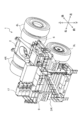
- Fig. 1 is a side view of a dump truck 1.
- Fig. 2 is a perspective view of the dump truck 1.
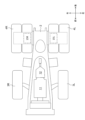
- Fig. 3 is a plan view of the vehicle body frame 2. Note that, unless otherwise specified, front, rear, left and right in this specification are based on the viewpoint of an operator who is riding on and operating the dump truck 1.
- a specific example of the transport vehicle is not limited to the dump truck 1, and may be a wheel loader, etc.
- the dump truck 1 of this embodiment mainly comprises a body frame 2 (vehicle body), a pair of front tires 3L, 3R rotatably supported on both left and right ends of the front part of the body frame 2, a pair of rear tires 4L, 4R rotatably supported on both left and right ends of the rear part of the body frame 2, a cargo bed 5 supported on the body frame 2 so as to be able to rise and fall, and a cab 6 in which an operator who operates the dump truck 1 rides.
- a body frame 2 vehicle body
- a pair of rear tires 4L, 4R rotatably supported on both left and right ends of the rear part of the body frame 2
- a cargo bed 5 supported on the body frame 2 so as to be able to rise and fall
- a cab 6 in which an operator who operates the dump truck 1 rides.
- the pair of front tires 3L, 3R are steered wheels whose steering angle changes according to the steering operation by the operator.
- the pair of rear tires 4L, 4R are drive wheels that rotate by transmitting the driving force of the travel motors 15L, 15R.
- the dump truck 1 is equipped with a pair of travel motors 15L, 15R in order to transmit the driving force independently to each of the pair of rear tires 4L, 4R.
- the loading platform 5 rises and falls vertically around a hinge pin 8 at the rear of the vehicle frame 2 as the hoist cylinders 7L, 7R expand and contract.
- One end of the hoist cylinders 7L, 7R is connected to the vehicle frame 2, and the other end is connected to the loading platform 5, and they expand and contract by receiving hydraulic oil from a hydraulic pump (not shown).
- a hydraulic pump not shown.
- the cab 6 is located at the left end on the deck 9 at the front end of the body frame 2.
- the cab 6 forms a driver's cab in which an operator who operates the dump truck 1 sits.
- an operating device 20 (see FIG. 4) for operating the dump truck 1 is located inside the cab 6, inside the cab 6, an operating device 20 (see FIG. 4) for operating the dump truck 1 is located. When the operator in the cab 6 operates the operating device 20, the dump truck 1 travels (accelerates, brakes, turns) and the loading platform 5 is raised and lowered.
- FIG. 4 is a diagram showing the inside of the cab 6.
- the operation device 20 includes, for example, a steering wheel 21, an accelerator pedal 22, and a brake pedal 23 shown in FIG. 4, as well as a travel lever and a hoist lever.
- the operation device 20 outputs an operation signal corresponding to a user's operation to a controller 30 (see FIG. 6) described later.
- the steering wheel 21 is an operating device that indicates the turning direction of the dump truck 1.
- the accelerator pedal 22 is an operating device that indicates the acceleration of the dump truck 1.
- the brake pedal 23 is an operating device that indicates the braking of the dump truck 1 (rear tires 4L, 4R).
- the travel lever is an operating device that indicates the traveling direction (forward position, reverse position, neutral position) of the dump truck 1 when the accelerator pedal 22 is depressed.
- the hoist lever is an operating device that indicates the raising and lowering of the loading platform 5 (upright position, lying position).
- the dump truck 1 is provided with a drive circuit 10 that drives the dump truck 1.
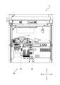
- the diesel engine 11, the generator 12, and the exhaust gas purification device 18 are mounted on the vehicle frame 2
- the travel motors 15L and 15R are mounted on the rear axle
- the AC/DC converter 13 the inverters 14L and 14R, the chopper 16, and the grid box 17 are disposed on the deck 9.
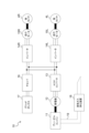
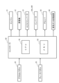
- FIG. 5 is a circuit diagram of a drive circuit 10 mounted on a dump truck 1.
- the drive circuit 10 mainly includes, for example, a diesel engine 11, a generator 12, an AC/DC converter 13, inverters 14L and 14R, travel motors 15L and 15R, a chopper 16, a grid box 17, and an exhaust gas purification device 18.
- the diesel engine 11 generates driving force for driving the dump truck 1 by burning fuel (light oil).
- the generator 12 is connected to the output shaft of the diesel engine 11.
- the driving force of the diesel engine 11 is transmitted to the generator 12, which generates three-phase AC power.
- the AC/DC converter 13 converts the three-phase AC power output from the generator 12 into DC power and outputs it to the inverters 14L, 14R and the chopper 16.
- the inverters 14L, 14R convert the DC power output from the AC/DC converter 13 into three-phase AC power and output it to the travel motors 15L, 15R.
- the travel motors 15L, 15R receive three-phase AC power from the inverters 14L, 14R and generate driving force to rotate the rear tires 4L, 4R.
- the driving force of the travel motors 15L, 15R is then transmitted to the rear tires 4L, 4R via a reduction gear (not shown), causing the dump truck 1 to travel (accelerate).
- the travel motors 15L, 15R operate as electric brakes.
- the travel motors 15L, 15R operating as electric brakes generate regenerative power and output it to the inverters 14L, 14R.
- the inverters 14L, 14R convert the three-phase AC regenerative power output from the travel motors 15L, 15R into DC power and output it to the chopper 16.
- the chopper 16 supplies the power output from the AC/DC converter 13 and the inverters 14L and 14R to the grid box 17.
- the grid box 17 is a resistor that converts the power generated by at least one of the generator 12 and the traction motors 15L and 15R into heat and consumes it.
- the exhaust gas purification device 18 is provided in the middle of a muffler 19 (exhaust pipe) for discharging exhaust gas generated by the diesel engine 11 to the outside of the dump truck 1.
- the exhaust gas purification device 18 includes both or only one of a urea SCR (Selective Catalytic Reduction) system that removes nitrogen oxides (NOx) contained in the exhaust gas flowing through the muffler 19, and a DPF (Diesel Particulate Filter) that removes particulate matter (PM, Particulate Matter) such as soot.
- the exhaust gas purification device 18 may also remove carbon monoxide and hydrocarbons contained in the exhaust gas flowing through the muffler 19 by oxidizing them with an oxidation catalyst. Particulate matter (PM), nitrogen oxides (NOx), and hydrocarbons (HC) are examples of harmful substances contained in exhaust gas.
- the exhaust gas purification device 18 removes nitrogen oxides (NOx) from the exhaust gas flowing through the muffler 19, and discharges the exhaust gas from which the nitrogen oxides have been removed into the atmosphere. More specifically, the exhaust gas purification device 18 injects urea into the exhaust gas flowing through the muffler 19, and breaks down the nitrogen oxides contained in the exhaust gas with ammonia into water and nitrogen. In addition, the exhaust gas purification device 18 (DPF) captures particulate matter (PM, such as soot) contained in the exhaust gas using a filter, and discharges the exhaust gas from which the PM has been removed into the atmosphere.
- PM particulate matter
- FIG. 6 is a hardware configuration diagram of the dump truck 1.
- the dump truck 1 is equipped with a controller 30.
- the controller 30 may include, for example, a DSC (Digital Signal Controller) that controls the overall operation of the dump truck 1, and an ECU (Engine Control Unit) that controls the operation of the diesel engine 11.
- DSC Digital Signal Controller
- ECU Engine Control Unit
- the controller 30 comprises a CPU (Central Processing Unit) 31 and a memory 32.
- the memory 32 is, for example, a ROM (Read Only Memory), a RAM (Random Access Memory), a HDD (Hard Disk Drive), or a combination of these.
- the controller 30 realizes the processing described below by the CPU 31 reading and executing program code stored in the ROM or HDD.
- the RAM is used as a work area when the CPU 31 executes a program.
- controller 30 is not limited to this, and may be realized by hardware such as an ASIC (Application Specific Integrated Circuit) or an FPGA (Field-Programmable Gate Array).
- ASIC Application Specific Integrated Circuit
- FPGA Field-Programmable Gate Array
- the controller 30 controls the diesel engine 11, the generator 12, the AC/DC converter 13, the inverters 14L and 14R, and the chopper 16, for example, based on an operation signal output from the operation device 20.
- the controller 30 increases the rotation speed of the diesel engine 11, outputs the electricity generated by the generator 12 to the inverters 14L, 14R, and controls the inverters 14L, 14R to increase the rotation speed of the travel motors 15L, 15R.
- the accelerator pedal 22 outputs an operation signal that indicates the amount of depression (accelerator operation amount). The greater the amount of depression indicated by the operation signal, the higher the controller 30 increases the rotation speed of the travel motors 15L, 15R.
- the controller 30 In response to depression of the brake pedal 23, the controller 30 reduces the rotation speed of the diesel engine 11 and operates the travel motors 15L, 15R as electric brakes.
- the controller 30 outputs regenerative power generated by the travel motors 15L, 15R to the chopper 16 via the inverters 14L, 14R.
- the regenerative power generated by the travel motors 15L, 15R is converted to heat in the grid box 17 and consumed.
- the brake pedal 23 outputs an operation signal indicating the depression amount B (amount of brake operation).
- the controller 30 increases the braking force (regenerative power) of the rear tires 4R, 4L the greater the depression amount B indicated by the operation signal.
- the controller 30 increases or decreases the amount of power generated by the generator 12 within a range of the maximum power generation amount determined according to the rotation speed of the diesel engine 11. More specifically, the controller 30 causes the generator 12 to generate running power to be supplied to the traveling motors 15L, 15R and auxiliary power to be supplied to auxiliary equipment (not shown) mounted on the dump truck 1.
- the running power increases or decreases according to, for example, the depression amount of the accelerator pedal 22.
- the auxiliary power increases or decreases according to whether the auxiliary equipment is driven or stopped.
- the controller 30 causes the generator 12 to additionally generate additional power P L or consumable power P R in addition to the running power and auxiliary power.
- the cleaning process is a process for removing hydrocarbons (HS) deposited in the exhaust gas purification device 18 (urea SCR system). More specifically, when the diesel engine 11 is driven at a low load, hydrocarbons are generated. These hydrocarbons flow through the muffler 19 together with the exhaust gas and are deposited on the surface of the exhaust gas purification device 18. The hydrocarbons deposited on the surface can cause the exhaust gas purification device 18 to malfunction.
- the cleaning process is a process for removing particulate matter (PM) deposited in the exhaust gas purification device 18 (DPF). More specifically, when the diesel engine 11 is driven, PM (e.g., soot) is generated. This PM flows through the muffler 19 together with the exhaust gas and is deposited in the filter section of the exhaust gas purification device 18. The deposited PM can cause the exhaust gas purification device 18 to malfunction.
- PM particulate matter
- the controller 30 removes hydrocarbons and the like that have accumulated on the surface of the exhaust gas purification device 18 by increasing the temperature of the exhaust gas.
- the temperature of the exhaust gas increases by increasing the load on the diesel engine 11.
- Increasing the amount of power generated by the generator 12 increases the load on the diesel engine 11.
- Increasing the rotation speed of the diesel engine 11 also increases the flow rate of the exhaust gas.
- the operator may depress the accelerator pedal 22, or the controller 30 may adjust the rotation speed of the diesel engine 11.
- the memory 32 holds a counter.
- the controller 30 counts up the counter when the exhaust temperature of the diesel engine 11 remains below a predetermined value for a predetermined period of time.
- the controller 30 counts down the counter when the exhaust temperature of the diesel engine 11 remains above a predetermined value for a predetermined period of time.
- the controller 30 then executes a cleaning process when the counter value exceeds a threshold value. Furthermore, the controller 30 resets the counter (assigns 0) when the cleaning process has been executed.
- [Cleaning Process According to the First Embodiment] 7 is a flowchart of the cleaning process according to the first embodiment.
- the controller 30 specifies the additional power P L that is additionally generated by the generator 12 when a load required for raising the exhaust gas of the diesel engine 11 to the cleaning temperature is applied to the generator 12 (S11).
- the controller 30 also specifies the consumable power P R that can be additionally consumed by the grid box 17 (S12). Note that the additional power P L and the consumable power P R change depending on the traveling state of the dump truck 1.
- the cleaning temperature is the temperature of the exhaust gas required to remove hydrocarbons and the like deposited on the surface of the exhaust gas purification device 18.
- the cleaning temperature is determined in advance and stored in the memory 32.
- the additional power P L is a value obtained by subtracting the traveling power and the auxiliary power from the required power that the generator 12 should generate in order to generate the load required to raise the exhaust gas to the cleaning temperature.
- the required power traveling power + auxiliary power + additional power P L.
- the additional power P L 0.
- step S13 is an example of a process for determining whether or not the additional power P L additionally generated by the generator 12 can be consumed in the grid box 17 when a load required to raise the exhaust gas temperature to the cleaning temperature is generated in the generator 12 (i.e., the required power is generated by the generator 12).
- the controller 30 determines that the grid box 17 can consume the additional power P L. Then, the controller 30 causes the generator 12 to additionally generate the additional power P L (in other words, causes the generator 12 to generate the required power) (S14). As a result, the exhaust gas rises to a cleaning temperature, and hydrocarbons and the like deposited on the surface of the exhaust gas purification device 18 are removed (cleaned). The controller 30 also causes the grid box 17 to additionally consume the additional power P L (S15). Furthermore, the controller 30 may prompt the operator to depress the accelerator pedal 22 through a notification device provided in the cab 6. As a result, the flow rate of the exhaust gas at the cleaning temperature increases.
- the controller 30 determines that the additional power P L cannot be consumed in the grid box 17. Next, the controller 30 compares the difference (P L - P R ) between the additional power P L and the consumable power P R with the threshold value P th .
- the threshold value P th is set, for example, to a value that can raise the temperature of the exhaust gas to a temperature close to the cleaning temperature when the consumable power P R is additionally generated by the generator 12.
- the controller 30 causes the generator 12 to additionally generate the consumable power P R (S17). This causes the temperature of the exhaust gas to rise to a temperature close to the cleaning temperature. The controller 30 also causes the grid box 17 to additionally consume the consumable power P R (S18).
- the controller 30 proceeds to the process of step S19 without executing the processes of steps S17 to S18.
- the controller 30 determines whether cleaning of the exhaust gas purification device 18 is complete (S19).
- the controller 30 may determine that cleaning is complete when, for example, a predetermined time has elapsed since the temperature of the exhaust gas detected by a temperature sensor (not shown) reached the cleaning temperature. If the controller 30 determines that cleaning is not yet complete (S19: No), it executes the processing from step S11 onwards again. In other words, the controller 30 repeatedly executes the processing from step S11 to S18 until cleaning is complete.
- the controller 30 determines that cleaning is complete (S19: Yes), it ends the cleaning process. In other words, the controller 30 causes the generator 12 to generate running power and auxiliary power, and causes the grid box 17 to consume the regenerative power.
- the first embodiment provides the following effects, for example:
- the additional power P L when the consumable power P R is equal to or greater than the additional power P L (S13: Yes), even if a load required to raise the exhaust gas temperature to the cleaning temperature is generated in the generator 12 (S14), the additional power P L additionally generated by the generator 12 can be consumed in the grid box 17.
- the grid box 17 is an existing facility that has conventionally been mounted on the dump truck 1 in order to consume regenerative power, and therefore cleaning of the exhaust gas purification device 18 can be realized while suppressing increases in weight and cost.
- the generator 12 when the consumable power P R is less than the additional power P L and the difference between the additional power P L and the consumable power P R is less than the threshold value P th (S13: No and S16: Yes), the generator 12 additionally generates the consumable power P R (S17), so that although cleaning cannot be performed immediately, the exhaust gas can be brought closer to the cleaning temperature.
- the consumable power P R for example, when the brake pedal 23 is released
- the time required to raise the exhaust gas to the cleaning temperature can be shortened.
- step S16 can be omitted.
- the controller 30 may execute the processing of steps S17 to S18 when the consumable power P R is less than the additional power P L.
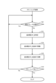
- [Cleaning Process According to the Second Embodiment] 8 shows the cleaning process according to the second embodiment. Note that detailed description of the process common to the first embodiment will be omitted, and differences will be mainly described.
- the structure of the dump truck 1 according to the second embodiment is common to the first embodiment.
- the cleaning process according to the second embodiment differs from the first embodiment in the method (S21) of determining whether or not the additional power P L additionally generated by the generator 12 can be consumed in the grid box 17 when a load required for raising the exhaust gas to the cleaning temperature is generated in the generator 12.
- the controller 30 determines whether the traveling motors 15L, 15R are generating regenerative power (in other words, whether the brake pedal 23 is depressed) (S21). If the traveling motors 15L, 15R are generating regenerative power (S21: Yes), the controller 30 waits for execution of the processes in steps S11 and onward. On the other hand, if the traveling motors 15L, 15R are not generating regenerative power (S21: No), the controller 30 determines that the grid box 17 can consume additional power P L , and executes the processes in steps S11 to S19.
- cleaning of the exhaust gas purification device 18 can be achieved while suppressing increases in weight and cost. Moreover, the method of determining whether the additional electric power P L additionally generated by the generator 12 can be consumed in the grid box 17 when a load required for raising the exhaust gas to the cleaning temperature is generated in the generator 12 is simpler than in the first embodiment, so the processing load of the controller 30 is reduced.
Landscapes
- Engineering & Computer Science (AREA)
- Chemical & Material Sciences (AREA)
- Mechanical Engineering (AREA)
- Toxicology (AREA)
- Health & Medical Sciences (AREA)
- Combustion & Propulsion (AREA)
- Chemical Kinetics & Catalysis (AREA)
- General Engineering & Computer Science (AREA)
- Power Engineering (AREA)
- Automation & Control Theory (AREA)
- Transportation (AREA)
- Exhaust Gas After Treatment (AREA)
- Hybrid Electric Vehicles (AREA)
Priority Applications (3)
| Application Number | Priority Date | Filing Date | Title |
|---|---|---|---|
| JP2025506301A JP7747933B2 (ja) | 2023-03-13 | 2023-03-13 | 運搬車両 |
| CN202380057889.4A CN119677942A (zh) | 2023-03-13 | 2023-03-13 | 运输车辆 |
| PCT/JP2023/009711 WO2024189751A1 (ja) | 2023-03-13 | 2023-03-13 | 運搬車両 |
Applications Claiming Priority (1)
| Application Number | Priority Date | Filing Date | Title |
|---|---|---|---|
| PCT/JP2023/009711 WO2024189751A1 (ja) | 2023-03-13 | 2023-03-13 | 運搬車両 |
Publications (1)
| Publication Number | Publication Date |
|---|---|
| WO2024189751A1 true WO2024189751A1 (ja) | 2024-09-19 |
Family
ID=92754633
Family Applications (1)
| Application Number | Title | Priority Date | Filing Date |
|---|---|---|---|
| PCT/JP2023/009711 Pending WO2024189751A1 (ja) | 2023-03-13 | 2023-03-13 | 運搬車両 |
Country Status (3)
| Country | Link |
|---|---|
| JP (1) | JP7747933B2 (enExample) |
| CN (1) | CN119677942A (enExample) |
| WO (1) | WO2024189751A1 (enExample) |
Citations (4)
| Publication number | Priority date | Publication date | Assignee | Title |
|---|---|---|---|---|
| JP5864036B1 (ja) | 2014-12-01 | 2016-02-17 | 株式会社小松製作所 | ダンプトラック |
| JP6438273B2 (ja) | 2014-10-28 | 2018-12-12 | 日立建機株式会社 | エンジン発電機制御装置およびそれを備えた鉱山向けダンプトラック |
| WO2020091750A1 (en) | 2018-10-31 | 2020-05-07 | Cummins Inc. | Inverter-based exhaust aftertreatment thermal management apparatuses, methods, systems, and techniques |
| JP7005389B2 (ja) | 2018-03-02 | 2022-01-21 | 三菱重工業株式会社 | 車両の排ガス処理装置 |
-
2023
- 2023-03-13 JP JP2025506301A patent/JP7747933B2/ja active Active
- 2023-03-13 CN CN202380057889.4A patent/CN119677942A/zh active Pending
- 2023-03-13 WO PCT/JP2023/009711 patent/WO2024189751A1/ja active Pending
Patent Citations (4)
| Publication number | Priority date | Publication date | Assignee | Title |
|---|---|---|---|---|
| JP6438273B2 (ja) | 2014-10-28 | 2018-12-12 | 日立建機株式会社 | エンジン発電機制御装置およびそれを備えた鉱山向けダンプトラック |
| JP5864036B1 (ja) | 2014-12-01 | 2016-02-17 | 株式会社小松製作所 | ダンプトラック |
| JP7005389B2 (ja) | 2018-03-02 | 2022-01-21 | 三菱重工業株式会社 | 車両の排ガス処理装置 |
| WO2020091750A1 (en) | 2018-10-31 | 2020-05-07 | Cummins Inc. | Inverter-based exhaust aftertreatment thermal management apparatuses, methods, systems, and techniques |
Also Published As
| Publication number | Publication date |
|---|---|
| CN119677942A (zh) | 2025-03-21 |
| JP7747933B2 (ja) | 2025-10-01 |
| JPWO2024189751A1 (enExample) | 2024-09-19 |
Similar Documents
| Publication | Publication Date | Title |
|---|---|---|
| CN103080488B (zh) | 用于柴油机颗粒过滤器再生的方法和系统 | |
| JP5808997B2 (ja) | ハイブリッド自動車の制御装置 | |
| JP2011085092A (ja) | シリーズハイブリッド車のdpf再生装置 | |
| CN110139973B (zh) | 发动机式叉车的运行中dpf再生系统及其方法 | |
| JP3775391B2 (ja) | 車両用の電力制御装置 | |
| JP4372771B2 (ja) | 連結自動車とその走行方法 | |
| JP3807399B2 (ja) | 内燃機関の排気浄化装置 | |
| JP2007204004A (ja) | 車両の減速制御装置 | |
| JP7747933B2 (ja) | 運搬車両 | |
| JP2015009939A (ja) | ラフテレーンクレーン | |
| JP2014227009A (ja) | ハイブリッド車両及びその制御方法 | |
| CN103080494B (zh) | 用于废气净化的方法和系统 | |
| US12163452B2 (en) | Electronic device, vehicle, and control method | |
| CN114458430B (zh) | 控制车辆中的发动机系统的操作的方法 | |
| JP6260118B2 (ja) | ハイブリッド車両及びその制御方法 | |
| JP6115307B2 (ja) | ハイブリッド電動車両及びその制御方法 | |
| JP6145076B2 (ja) | ハイブリッド作業機械 | |
| JP2002303175A (ja) | ハイブリッドシステムの制御装置 | |
| JP2015077839A (ja) | ハイブリッド車両の車重の推定システム及びその推定方法 | |
| US20240278769A1 (en) | Vehicle | |
| JP2005282528A (ja) | ハイブリッド電気自動車 | |
| JP7727570B2 (ja) | ダンプトラック | |
| JP2024049135A (ja) | ダンプトラック | |
| JP2023118207A (ja) | ダンプトラック | |
| JP2005282527A (ja) | ハイブリッド電気自動車 |
Legal Events
| Date | Code | Title | Description |
|---|---|---|---|
| 121 | Ep: the epo has been informed by wipo that ep was designated in this application |
Ref document number: 23927373 Country of ref document: EP Kind code of ref document: A1 |
|
| WWE | Wipo information: entry into national phase |
Ref document number: 2025506301 Country of ref document: JP |
|
| WWE | Wipo information: entry into national phase |
Ref document number: 202380057889.4 Country of ref document: CN |
|
| WWP | Wipo information: published in national office |
Ref document number: 202380057889.4 Country of ref document: CN |
|
| WWE | Wipo information: entry into national phase |
Ref document number: 2023927373 Country of ref document: EP |
|
| NENP | Non-entry into the national phase |
Ref country code: DE |
|
| ENP | Entry into the national phase |
Ref document number: 2023927373 Country of ref document: EP Effective date: 20251013 |
|
| ENP | Entry into the national phase |
Ref document number: 2023927373 Country of ref document: EP Effective date: 20251013 |
|
| ENP | Entry into the national phase |
Ref document number: 2023927373 Country of ref document: EP Effective date: 20251013 |
|
| ENP | Entry into the national phase |
Ref document number: 2023927373 Country of ref document: EP Effective date: 20251013 |
|
| ENP | Entry into the national phase |
Ref document number: 2023927373 Country of ref document: EP Effective date: 20251013 |