WO2024176804A1 - 回転電機 - Google Patents
回転電機 Download PDFInfo
- Publication number
- WO2024176804A1 WO2024176804A1 PCT/JP2024/003820 JP2024003820W WO2024176804A1 WO 2024176804 A1 WO2024176804 A1 WO 2024176804A1 JP 2024003820 W JP2024003820 W JP 2024003820W WO 2024176804 A1 WO2024176804 A1 WO 2024176804A1
- Authority
- WO
- WIPO (PCT)
- Prior art keywords
- slot
- winding
- wound
- phase wire
- phase
- Prior art date
- Legal status (The legal status is an assumption and is not a legal conclusion. Google has not performed a legal analysis and makes no representation as to the accuracy of the status listed.)
- Ceased
Links
Images



Classifications
-
- H—ELECTRICITY
- H02—GENERATION; CONVERSION OR DISTRIBUTION OF ELECTRIC POWER
- H02K—DYNAMO-ELECTRIC MACHINES
- H02K3/00—Details of windings
- H02K3/04—Windings characterised by the conductor shape, form or construction, e.g. with bar conductors
- H02K3/28—Layout of windings or of connections between windings
Definitions
- the present invention relates to a rotating electric machine.
- Patent document 1 discloses the stator structure of a multi-phase motor (rotating electric machine) that has two three-phase coils.
- the present invention aims to provide a rotating electric machine with two three-phase coils, the winding structure of which is designed to match the phases of like phases.
- a rotating electric machine includes a stator configured such that a winding passes an odd number of times through each of a plurality of slots, a first U-phase wire wound in the plurality of slots, a first V-phase wire wound in the plurality of slots, a first W-phase wire wound in the plurality of slots, a second U-phase wire wound in the plurality of slots, a second V-phase wire wound in the plurality of slots, a second W-phase wire wound in the plurality of slots, and a front end of the first U-phase wire, the first V-phase wire, and the first W-phase wire.
- the second U-phase wire being wound in a slot position where the current flow direction is reversed and shifted by 180 degrees in electrical angle with respect to the first U-phase wire
- the second V-phase wire being wound in a slot position where the current flow direction is reversed and shifted by 180 degrees in electrical angle with respect to the first V-phase wire
- the second W-phase wire being wound in a slot position where the current flow direction is reversed and shifted by 180 degrees in electrical angle with respect to the first W-phase wire.
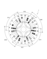
- FIG. 1 is a configuration diagram showing a rotating electric machine according to an embodiment of the present invention as viewed from the side opposite to the lead wires.
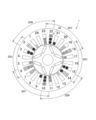
- FIG. 2 is a configuration diagram showing only the first three-phase coil in FIG.
- FIG. 3 is a configuration diagram showing only the second three-phase coil in FIG.
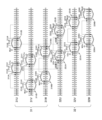
- FIG. 4 is a development of windings as viewed from the inner circumference with the lead wire side facing up in a rotating electrical machine.
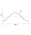
- FIG. 5 is a graph showing the time variation of induced voltage when two identical phase windings are wound in different ways.
- FIG. 6 is a graph showing the time change of the induced voltage when the windings of two identical phases in FIG. 5 are shifted from each other by 180 electrical degrees.
- FIG. 7 is a graph showing the change over time of the induced voltage when the current passing direction of one phase is reversed from that shown in FIG.
- Fig. 1 is a configuration diagram showing the rotating electric machine 1 as viewed from the side opposite the lead wires.
- Fig. 2 is a configuration diagram showing only the first three-phase coil 31 in Fig. 1.
- Fig. 3 is a configuration diagram showing only the second three-phase coil 32 in Fig. 1.
- a circle with an x inside it indicates that the winding 30 is wound from the front to the back, and current flows from the front to the back.
- a circle with a ⁇ inside it indicates that the winding 30 is wound from the back to the front, and current flows from the back to the front.
- the rotating electric machine 1 includes a rotor 10 as a rotor and a stator 20 as a stator.
- the rotating electric machine 1 is an electric motor having two three-phase coils (a first three-phase coil 31 and a second three-phase coil 32) (see FIG. 2 and FIG. 3).
- the rotating electric machine 1 is mounted on a vehicle, for example, and can be used as both an electric motor that generates driving force and a generator that generates regenerative power by being driven.
- the direction of the central axis of the rotating electric machine 1 is referred to as the "axial direction”
- the direction of rotation of the rotor 10 in the rotating electric machine 1 is referred to as the “circumferential direction”
- the direction extending radially from the central axis of the rotating electric machine 1 is referred to as the "radial direction”.
- the rotor 10 has a rotor core 11, a rotor shaft 12, and a plurality of permanent magnets 13.
- the rotor 10 is a common rotor that rotates due to the magnetic fields generated by the first U-phase wire 31U, the first V-phase wire 31V, the first W-phase wire 31W, the second U-phase wire 32U, the second V-phase wire 32V, and the second W-phase wire 32W, which will be described later.
- the rotor core 11 is formed in a generally cylindrical shape extending in the axial direction.
- the rotor core 11 has a through hole that penetrates in the axial direction.
- the rotor shaft 12 is provided in the through hole.
- the rotor core 11 is rotatably supported by the rotor shaft 12.
- Multiple permanent magnets 13 are housed within the rotor core 11.
- four sets (eight pieces) of permanent magnets 13 are provided to correspond to the four poles, but the number is not limited to this.
- the stator 20 is a four-pole stator.
- the stator 20 has a stator core 21 as a common core, and a winding 30.
- the stator 20 is formed by winding a first U-phase wire 31U, a first V-phase wire 31V, a first W-phase wire 31W, a second U-phase wire 32U, a second V-phase wire 32V, and a second W-phase wire 32W, which will be described later, around the stator core 21.
- the stator core 21 is formed in a generally cylindrical shape extending in the axial direction.
- the stator core 21 has a through hole that penetrates in the axial direction.
- the rotor 10 is arranged in the through hole so that it can rotate freely relative to the stator core 21.
- the stator core 21 has a plurality of teeth 22 (24 in this case) and a plurality of slots 23 (24 in this case).
- the teeth 22 protrude radially inward from the inner circumferential surface of the stator core 21.
- the teeth 22 are arranged at equal intervals in the circumferential direction on the inner circumferential surface of the stator core 21.
- the slots 23 are each formed between a pair of teeth 22 adjacent in the circumferential direction.
- the slots 23 open into the through holes of the stator core 21.
- the multiple slots 23 are arranged at equal intervals in the circumferential direction on the inner peripheral surface of the stator core 21.
- the slots 23 include a first slot 23a, a second slot 23b, a third slot 23c, a fourth slot 23d, a fifth slot 23e, a sixth slot 23f, a seventh slot 23g, an eighth slot 23h, a ninth slot 23i, a tenth slot 23j, an eleventh slot 23k, a twelfth slot 23l, a thirteenth slot 23m, a fourteenth slot 23n, a fifteenth slot 23o, a sixteenth slot 23p, a seventeenth slot 23q, an eighteenth slot 23r, a nineteenth slot 23s, a twentieth slot 23t, a twenty-first slot 23u, a twenty-second slot 23v, a twenty-third slot 23w, and a twenty-fourth slot 23x.
- the first to 24th slots 23a to 23x are arranged in order so that they are adjacent to each other in the circumferential direction, and the 24th slot 23x and the first slot 23a are adjacent to each other in the circumferential direction, so that they are arranged at equal intervals around the entire circumference.
- Each of the multiple slots 23 is configured so that the winding 30 passes through it an odd number of times.
- the stator 20 is configured so that the winding 30 passes through each of the multiple slots 23 three times. This makes it possible to minimize the number of windings and improve manufacturability. In other words, one aspect of the present invention works particularly well in such cases, making it easier to align the number of passes of the winding 30 through each slot 23.
- FIG. 4 is an exploded view of the winding 30 as seen from the inner circumference with the lead wire side facing up in the rotating electric machine 1.
- the winding 30 has a first three-phase coil 31 and a second three-phase coil 32.
- the rotating electric machine 1 is a multi-phase motor having two three-phase coils (the first three-phase coil 31 and the second three-phase coil 32) wound around a single stator 20, forming a dual three-phase winding.
- the first three-phase coil 31 has a first U phase wire 31U, a first V phase wire 31V, and a first W phase wire 31W.
- the first three-phase coil 31 constitutes a three-phase, four-pole coil.
- the second three-phase coil 32 has a second U phase wire 32U, a second V phase wire 32V, and a second W phase wire 32W.
- the second three-phase coil 32 constitutes a three-phase, four-pole coil.
- the first U phase wire 31U, the first V phase wire 31V, the first W phase wire 31W, the second U phase wire 32U, the second V phase wire 32V, and the second W phase wire 32W are electrically independent of each other.
- the first U phase wire 31U is wound in multiple slots 23.
- the first U phase wire 31U has a first winding 31U1, a second winding 31U2, a third winding 31U3, a fourth winding 31U4, a fifth winding 31U5, and a sixth winding 31U6.
- the first winding 31U1 is constructed by winding the winding 30 input from the first U-phase lead wire U1in connected to a three-phase AC power supply (not shown) between the 13th slot 23m and the 8th slot 23h.
- the second winding 31U2 is constructed by winding the winding 30 between the 13th slot 23m and the 8th slot 23h, continuing from the first winding 31U1 wound in the 8th slot 23h.
- the third winding 31U3 is constructed by winding the winding 30 between the 12th slot 23l and the 7th slot 23g, continuing from the second winding 31U2 wound in the 8th slot 23h.
- the fourth winding 31U4 is wound between the first slot 23a and the twentieth slot 23t, continuing from the third winding 31U3 wound in the seventh slot 23g.
- the fifth winding 31U5 is wound between the first slot 23a and the twentieth slot 23t, continuing from the fourth winding 31U4 wound in the twentieth slot 23t.
- the sixth winding 31U6 is wound between the 24th slot 23x and the 19th slot 23s, continuing from the fifth winding 31U5 wound in the twentieth slot 23t. After being wound in the 19th slot 23s, the sixth winding 31U6 is connected to the first neutral point Mid1.
- the first U phase wire 31U has a first coil 31UA wound two times between the 13th slot 23m and the 8th slot 23h and one time between the 12th slot 23l and the 7th slot 23g, and a second coil 31UB wound two times between the 1st slot 23a and the 20th slot 23t and one time between the 24th slot 23x and the 19th slot 23s.
- the first V-phase wire 31V has a first winding 31V1, a second winding 31V2, a third winding 31V3, a fourth winding 31V4, a fifth winding 31V5, and a sixth winding 31V6.
- the first winding 31V1 is constructed by winding the winding 30 input from the first V-phase lead wire V1in connected to the three-phase AC power supply between the 17th slot 23q and the 12th slot 23l.
- the second winding 31V2 is constructed by winding the winding 30 between the 17th slot 23q and the 12th slot 23l, continuing from the first winding 31V1 wound in the 12th slot 23l.
- the third winding 31V3 is constructed by winding the winding 30 between the 16th slot 23p and the 11th slot 23k, continuing from the second winding 31V2 wound in the 12th slot 23l.
- the fourth winding 31V4 is wound between the fifth slot 23e and the twenty-fourth slot 24x, continuing from the third winding 31V3 wound in the eleventh slot 23k.
- the fifth winding 31V5 is wound between the fifth slot 23e and the twenty-fourth slot 23x, continuing from the fourth winding 31V4 wound in the twenty-fourth slot 23x.
- the sixth winding 31V6 is wound between the fourth slot 23d and the twenty-third slot 23w, continuing from the fifth winding 31V5 wound in the twenty-fourth slot 23x. After being wound in the twenty-third slot 23w, the sixth winding 31V6 is connected to the first neutral point Mid1.
- the first V phase wire 31V has a first coil 31VA that is wound two times between the 17th slot 23q and the 12th slot 23l and one time between the 16th slot 23p and the 11th slot 23k, and a second coil 31VB that is wound two times between the 5th slot 23e and the 24th slot 23x and one time between the 4th slot 23d and the 23rd slot 23w.
- the first W phase wire 31W has a first winding 31W1, a second winding 31W2, a third winding 31W3, a fourth winding 31W4, a fifth winding 31W5, and a sixth winding 31W6.
- the first winding 31W1 is constructed by winding the winding 30 input from the first W-phase lead wire W1in connected to the three-phase AC power supply between the 21st slot 23u and the 16th slot 23p.
- the second winding 31W2 is constructed by winding the winding 30 between the 21st slot 23u and the 16th slot 23p, continuing from the first winding 31W1 wound in the 16th slot 23p.
- the third winding 31W3 is constructed by winding the winding 30 between the 20th slot 23t and the 15th slot 23o, continuing from the second winding 31W2 wound in the 16th slot 23p.
- the fourth winding 31W4 is wound between the ninth slot 23i and the fourth slot 24d, continuing from the third winding 31W3 wound in the fifteenth slot 23o.
- the fifth winding 31W5 is wound between the ninth slot 23i and the fourth slot 23d, continuing from the fourth winding 31W4 wound in the fourth slot 23d.
- the sixth winding 31W6 is wound between the eighth slot 23h and the third slot 23c, continuing from the fifth winding 31W5 wound in the fourth slot 23d.
- the sixth winding 31V6 is wound in the third slot 23c and then connected to the first neutral point Mid1.
- the first W phase wire 31W has a first coil 31WA that is wound two times between the 21st slot 23u and the 16th slot 23p and one time between the 20th slot 23t and the 15th slot 23o, and a second coil 31WB that is wound two times between the 9th slot 23i and the 4th slot 23d and one time between the 8th slot 23h and the 3rd slot 23c.
- the second U-phase wire 32U is wound in a plurality of slots 23.
- the second U-phase wire 32U has a first winding 32U1, a second winding 32U2, a third winding 32U3, a fourth winding 32U4, a fifth winding 32U5, and a sixth winding 32U6.
- the first winding 32U1 is constructed by winding the winding 30 input from the second U-phase lead wire U2in connected to the three-phase AC power supply between the 13th slot 23m and the 18th slot 23r.
- the second winding 32U2 is constructed by winding the winding 30 between the 14th slot 23n and the 19th slot 23s, continuing from the first winding 32U1 wound in the 18th slot 23r.
- the third winding 32U3 is constructed by winding the winding 30 between the 14th slot 23n and the 19th slot 23s, continuing from the second winding 32U2 wound in the 19th slot 23s.
- the fourth winding 32U4 is wound between the first slot 23a and the sixth slot 23f, continuing from the third winding 32U3 wound in the 19th slot 23s.
- the fifth winding 32U5 is wound between the second slot 23b and the seventh slot 23g, continuing from the fourth winding 32U4 wound in the sixth slot 23f.
- the sixth winding 32U6 is wound between the second slot 23b and the seventh slot 23g, continuing from the fifth winding 32U5 wound in the seventh slot 23g. After being wound in the seventh slot 23g, the sixth winding 32U6 is connected to the second neutral point Mid2.
- the second U phase wire 32U has a first coil 32UA that is wound once between the 13th slot 23m and the 18th slot 23r and two turns between the 14th slot 23n and the 19th slot 23s, and a second coil 32UB that is wound once between the 1st slot 23a and the 6th slot 23f and two turns between the 2nd slot 23b and the 7th slot 23g.
- the second U phase wire 32U is wound in a slot position where the current flow direction is reversed and shifted by 180 electrical degrees (90 mechanical degrees) from the first U phase wire 31U.
- the second V-phase wire 32V has a first winding 32V1, a second winding 32V2, a third winding 32V3, a fourth winding 32V4, a fifth winding 32V5, and a sixth winding 32V6.
- the first winding 32V1 is configured by winding the winding 30 input from the second V-phase lead wire V2in connected to the three-phase AC power supply between the 17th slot 23q and the 22nd slot 23v.
- the second winding 32V2 is configured by winding the winding 30 between the 18th slot 23r and the 23rd slot 23w, continuing from the first winding 32V1 wound in the 22nd slot 23v.
- the third winding 32V3 is configured by winding the winding 30 between the 18th slot 23r and the 23rd slot 23w, continuing from the second winding 32V2 wound in the 23rd slot 23w.
- the fourth winding 32V4 is wound between the fifth slot 23e and the tenth slot 24j, continuing from the third winding 32V3 wound in the 23rd slot 23w.
- the fifth winding 32V5 is wound between the sixth slot 23f and the 11th slot 23k, continuing from the fourth winding 32V4 wound in the 10th slot 23j.
- the sixth winding 32V6 is wound between the sixth slot 23f and the 11th slot 23k, continuing from the fifth winding 32V5 wound in the 11th slot 23k. After being wound in the 11th slot 23k, the sixth winding 32V6 is connected to the second neutral point Mid2.
- the second V phase wire 32V has a first coil 32VA that is wound once between the 17th slot 23q and the 22nd slot 23v and two times between the 18th slot 23r and the 23rd slot 23w, and a second coil 32VB that is wound once between the 5th slot 23e and the 10th slot 23j and two times between the 6th slot 23f and the 11th slot 23k.
- the second V-phase wire 32V is wound in a slot position where the current flow direction is reversed and shifted by 180 electrical degrees (90 mechanical degrees) from the first V-phase wire 31V.
- the second W phase wire 32W has a first winding 32W1, a second winding 32W2, a third winding 32W3, a fourth winding 32W4, a fifth winding 32W5, and a sixth winding 32W6.
- the first winding 32W1 is configured by winding the winding 30 input from the second W-phase lead wire W2in connected to the three-phase AC power supply between the 21st slot 23u and the 2nd slot 23b.
- the second winding 32W2 is configured by winding the winding 30 between the 22nd slot 23v and the 3rd slot 23c, continuing from the first winding 32W1 wound in the 2nd slot 23b.
- the third winding 32W3 is configured by winding the winding 30 between the 22nd slot 23v and the 3rd slot 23c, continuing from the second winding 32W2 wound in the 3rd slot 23c.
- the fourth winding 32W4 is wound between the ninth slot 23i and the fourteenth slot 24n, continuing from the third winding 32W3 wound in the third slot 23c.
- the fifth winding 32W5 is wound between the tenth slot 23j and the fifteenth slot 23o, continuing from the fourth winding 32W4 wound in the fourteenth slot 23n.
- the sixth winding 32W6 is wound between the tenth slot 23j and the fifteenth slot 23o, continuing from the fifth winding 32W5 wound in the fifteenth slot 23o. After being wound in the fifteenth slot 23o, the sixth winding 32V6 is connected to the second neutral point Mid2.
- the second W phase wire 32W has a first coil 32WA that is wound once between the 21st slot 23u and the 2nd slot 23b and two times between the 22nd slot 23v and the 3rd slot 23c, and a second coil 32WB that is wound once between the 9th slot 23i and the 14th slot 23n and two times between the 10th slot 23j and the 15th slot 23o.
- the second W phase wire 32W is wound in a slot position where the current flow direction is reversed and shifted by 180 electrical degrees from the first W phase wire 31W.
- the first U-phase wire 31U, the first V-phase wire 31V, the first W-phase wire 31W, the second U-phase wire 32U, the second V-phase wire 32V, and the second W-phase wire 32W are configured as short-pitch windings in which the magnetic pole pitch is different from the coil pitch.
- short-pitch windings which allow the coil pitch to be variably set, make it easier to align the number of times the winding 30 passes through each slot 23.
- Figure 5 is a graph showing the time change in induced voltage when the windings 30 of two identical phases are wound in different styles.
- Figure 6 is a graph showing the time change in induced voltage when the windings 30 of two identical phases are shifted by 180 electrical degrees from Figure 5.
- Figure 7 is a graph showing the time change in induced voltage when the current flow direction of one phase is reversed from Figure 6.
- the winding 30 is configured to have an odd number of turns, passing through each of the multiple slots 23 an odd number of times, it is difficult to align the windings 30 of the same phase with the same number in one slot 23. Therefore, as shown in FIG. 5, the windings 30 of the two same phases are wound in different styles, and the positive peaks in the dielectric voltage waveforms are usually offset from each other. If the positive peaks in the dielectric voltage waveforms are offset from each other, precise coordinated control of the first U, V, W phase wires 31U, 31V, 31W and the second U, V, W phase wires 32U, 32V, 32W must be performed in order to rotate the rotor 10 smoothly, which increases the difficulty of control design.
- the positive and negative vertices of the two windings 30 of the same phase are shifted by 180 degrees in electrical angle to make them coincident.
- the positive and negative vertices coincide, the induced voltages are cancelled out. Therefore, as shown in FIG. 7, the negative vertex is inverted to a positive vertex by reversing the current flow direction. This makes it possible to make the vertices of the two windings 30 of the same phase coincident, even in a configuration with an odd number of turns that would require the windings 30 of the two same phases to have different formats. In other words, a design can be made in which the phases of the same phases coincide.
- control unit for the first U, V, W phase wires 31U, 31V, 31W and the control unit for the second U, V, W phase wires 32U, 32V, 32W are different control units (control units that control inverter circuits)
- the difficulty of control design can be reduced.
- the control unit for the first U, V, W phase wires 31U, 31V, 31W and the control unit for the second U, V, W phase wires 32U, 32V, 32W can be made into a common unit, and the same signal can be supplied to control elements of the same phase (for example, IGBTs (Insulated Gate Bipolar Transistors)), making it possible to reduce the number of parts.
- IGBTs Insulated Gate Bipolar Transistors
- the inverter circuit (IGBT, smoothing capacitor portion) can be common to the first U-, V-, W-phase wires 31U, 31V, 31W and the second U-, V-, W-phase wires 32U, 32V, 32W, or can be provided separately. If the inverter circuit is common, the advantage of reducing the number of parts can be enjoyed. On the other hand, if the inverter circuits are separate, the amount of current for each can be reduced compared to when the inverter circuits are common.
- the inverter circuit is common, for example, the amount of current required for the first U-phase wire 31U and the amount of current required for the second U-phase wire 32U must be supplied by a single wiring (power supply line), but if the inverter circuits are separate, the wiring can be separated and the amount of current supplied to a single wiring can be reduced.
- the power supply for each inverter circuit can be either common or separate.
- the power supply for each inverter circuit is common, the benefit of reducing the number of parts can be enjoyed.
- the power supplies for each inverter circuit are separate, the amount of current can be reduced compared to when a common power supply is used.
- the power supply for the inverter circuits is common, for example, the amount of current required for two inverter circuits needs to be supplied by a single wiring (power line), but if the power supplies for the inverter circuits are separate, the wiring can be separated and the amount of current supplied to a single wiring can be reduced.
- the rotating electric machine 1 includes a stator 20 configured such that a winding 30 passes an odd number of times through each of a plurality of slots 23, a first U phase wire 31U wound in the plurality of slots 23, a first V phase wire 31V wound in the plurality of slots 23, a first W phase wire 31W wound in the plurality of slots 23, a second U phase wire 32U wound in the plurality of slots 23, a second V phase wire 32V wound in the plurality of slots 23, a second W phase wire 32W wound in the plurality of slots 23, and a first U phase wire 31U, a first V phase wire 31V and a first W phase wire
- the rotor 10 rotates due to the magnetic fields generated by the first U-phase wire 31W, the second U-phase wire 32U, the second V-phase wire 32V, and the second W-phase wire 32W.
- the second U-phase wire 32U is wound in a slot position where the current flow direction is reversed and shifted by 180 degrees in electrical angle with respect to the first U-phase wire 31U
- the second V-phase wire 32V is wound in a slot position where the current flow direction is reversed and shifted by 180 degrees in electrical angle with respect to the first V-phase wire 31V
- the second W-phase wire 32W is wound in a slot position where the current flow direction is reversed and shifted by 180 degrees in electrical angle with respect to the first W-phase wire 31W.
- This configuration makes it possible to provide a rotating electric machine 1 having two three-phase coils (a first three-phase coil 31 and a second three-phase coil 32) with a winding structure designed to match the phases of like phases.
- the stator 20 is also configured so that the winding 30 passes through each of the multiple slots 23 three times.
- This configuration allows the number of windings to be kept to a minimum, aiming to improve manufacturability.
- One aspect of the present invention works particularly well in such cases, making it easier to align the number of passes of the winding 30 through each slot.
- stator 20 is configured as a short-pitch winding in which the magnetic pole pitch is different from the coil pitch.
- short-pitch winding which allows the coil pitch to be variably set, makes it easier to make the number of passes of the winding 30 through each slot 23 uniform.
- the winding 30 passes an odd number of times, it includes not only the case where a single winding 30 passes an odd number of times, but also the case where a winding 30 made up of a bundle of multiple conductors passes an odd number of times, or the case where a winding 30 made up of a set of conductors wound multiple times passes an odd number of times. Therefore, even if the number of wires constituting the bundle or the number of times wound multiple times is even, if the bundle of conductors or the set of conductors passes an odd number of times, it falls under the case where the winding 30 passes an odd number of times.
- the state is the same when the winding 30 passes through the same slot 23 twice and when two turns of the winding 30 are integrated and pass through the slot 23 once. Therefore, when two turns of the winding 30 are integrated and pass through the slot 23 once, this corresponds to the winding 30 passing through the slot 23 twice.
- Rotating electric machine 10
- Stator 23 slot 30 winding 31U first U-phase wire 31V first V-phase wire 31W first W-phase wire 32U second U-phase wire 32V second V-phase wire 32W second W-phase wire
Landscapes
- Engineering & Computer Science (AREA)
- Power Engineering (AREA)
- Windings For Motors And Generators (AREA)
Abstract
[課題]2つの三相コイルを有する回転電機において、同種の相どうしの位相を一致させるように設計された巻線構造を有する回転電機を提供する。 [解決手段]回転電機1は、複数のスロット23の各々において巻線30が奇数回通過するように構成されたステータ20と、第1U相線31Uと、第1V相線31Vと、第1W相線31Wと、第2U相線32Uと、第2V相線32Vと、第2W相線32Wと、ステータ20の発生する磁界により回転するロータ10と、を備え、第2U相線32Uは、第1U相線31Uに対して電流通過方向が反転しかつ電気角で180度ずれるスロット位置に巻回され、第2V相線32Vは、第1V相線31Vに対して電流通過方向が反転しかつ電気角で180度ずれるスロット位置に巻回され、第2W相線32Wは、第1W相線31Wに対して電流通過方向が反転しかつ電気角で180度ずれるスロット位置に巻回される。
Description
本発明は、回転電機に関する。
特許文献1には、2つの三相コイルを有する多相モータ(回転電機)の固定子構造が開示されている。
ところで、複数のスロットの各々において巻線が奇数回通過する奇数ターンの構成とすると、1つのスロット内において同種の相の巻線を同じ数に揃えることが難しい。そのため、2つの同種の相の巻線どうしは異なる形式で巻回されることになり、誘電電圧の波形における正の頂点が互いにずれることになるのが通常である。
本発明は、2つの三相コイルを有する回転電機において、同種の相どうしの位相を一致させるように設計された巻線構造を有する回転電機を提供することを目的とする。
本発明のある態様によれば、回転電機は、複数のスロットの各々において巻線が奇数回通過するように構成された固定子と、前記複数のスロットに巻回された第1U相線と、前記複数のスロットに巻回された第1V相線と、前記複数のスロットに巻回された第1W相線と、前記複数のスロットに巻回された第2U相線と、前記複数のスロットに巻回された第2V相線と、前記複数のスロットに巻回された第2W相線と、前記第1U相線と前記第1V相線と前記第1W相線と前記第2U相線と前記第2V相線と前記第2W相線との発生する磁界により回転する共通回転子と、を備え、前記第2U相線は、前記第1U相線に対して電流通過方向が反転しかつ電気角で180度ずれるスロット位置に巻回され、前記第2V相線は、前記第1V相線に対して電流通過方向が反転しかつ電気角で180度ずれるスロット位置に巻回され、前記第2W相線は、前記第1W相線に対して電流通過方向が反転しかつ電気角で180度ずれるスロット位置に巻回される。
本発明のある態様によれば、2つの三相コイルを有する回転電機において、同種の相どうしの位相を一致させるように設計された巻線構造を有する回転電機を提供することができる。
以下、図面を参照して、本発明の実施形態に係る回転電機1について説明する。
まず、図1から図3を参照して、回転電機1の構成について説明する。図1は、回転電機1を反リード線側から見た状態を示す構成図である。図2は、図1において第1三相コイル31のみを示す構成図である。図3は、図1において第2三相コイル32のみを示す構成図である。
図1から図3において、×が中に描かれている○は、手前から奥に向かって巻線30が巻回され、手前から奥に向かって電流が流れることを示している。●が中に描かれている○は、奥から手間に向かって巻線30が巻回され、奥から手間に向かって電流が流れることを示している。
図1に示すように、回転電機1は、回転子としてのロータ10と、固定子としてのステータ20と、を備える。ここでは、回転電機1は、2つの三相コイル(第1三相コイル31及び第2三相コイル32)を有する電動モータである(図2及び図3参照)。回転電機1は、例えば車両に搭載され、駆動力を発生する電動モータと、被駆動されることで回生電力を発生する発電機と、の双方に利用可能である。以下では、回転電機1の中心軸方向を「軸方向」と称し、回転電機1におけるロータ10の回転方向を「周方向」と称し、回転電機1の中心軸から放射状に延びる方向を「径方向」と称する。
ロータ10は、ロータコア11と、ロータシャフト12と、複数の永久磁石13と、を有する。ロータ10は、後述する第1U相線31Uと第1V相線31Vと第1W相線31Wと第2U相線32Uと第2V相線32Vと第2W相線32Wとの発生する磁界により回転する共通回転子である。
ロータコア11は、軸方向に延在する略円筒状に形成される。ロータコア11は、軸方向に貫通する貫通孔を有する。貫通孔には、ロータシャフト12が設けられる。ロータコア11は、ロータシャフト12によって回転可能に支持される。
複数の永久磁石13は、ロータコア11内に収容される。永久磁石13は、ここでは4極に対応して4組(8個)設けられるが、この数に限定されるものではない。
ステータ20は、4極の固定子である。ステータ20は、共通コアとしてのステータコア21と、巻線30と、を有する。ステータ20は、後述する第1U相線31Uと第1V相線31Vと第1W相線31Wと第2U相線32Uと第2V相線32Vと第2W相線32Wとがステータコア21に巻回されてなる。
ステータコア21は、軸方向に延在する略円筒状に形成される。ステータコア21は、軸方向に貫通する貫通孔が設けられる。貫通孔には、ロータ10が相対回転自在に配置される。ステータコア21は、複数(ここでは24個)のティース22と、複数(ここでは24個)のスロット23と、を有する。
ティース22は、ステータコア21の内周面から径方向内側に突出する。複数のティース22は、ステータコア21の内周面において、周方向に等間隔に配置される。
スロット23は、周方向に隣り合う一対のティース22の間に各々形成される。スロット23は、ステータコア21の貫通孔に開口する。複数のスロット23は、ステータコア21の内周面において、周方向に等間隔に配置される。
具体的には、スロット23は、第1スロット23aと、第2スロット23bと、第3スロット23cと、第4スロット23dと、第5スロット23eと、第6スロット23fと、第7スロット23gと、第8スロット23hと、第9スロット23iと、第10スロット23jと、第11スロット23kと、第12スロット23lと、第13スロット23mと、第14スロット23nと、第15スロット23oと、第16スロット23pと、第17スロット23qと、第18スロット23rと、第19スロット23sと、第20スロット23tと、第21スロット23uと、第22スロット23vと、第23スロット23wと、第24スロット23xと、を有する。第1~24スロット23a~23xは、周方向に隣り合うように順に設けられ、第24スロット23xと第1スロット23aとが周方向に隣り合うことで、全周に等間隔に配置される。複数のスロット23は、各々において巻線30が奇数回通過するように構成される。
ここでは、ステータ20は、複数のスロット23の各々において巻線30が3回通過するように構成されている。これにより、巻線回数を最小限にとどめて製造性の向上を狙うことができる。即ち、本発明の一態様は、このような場合に特に好適に作用し、各スロット23の巻線30の通過回数を揃えやすくなる。
続いて、図4を併せて参照して、巻線30について説明する。図4は、回転電機1においてリード線側を上として内周から見た巻線30の展開図である。
巻線30は、第1三相コイル31と、第2三相コイル32と、を有する。即ち、回転電機1は、単一のステータ20に巻回される2つの三相コイル(第1三相コイル31及び第2三相コイル32)を有して二重三相巻線とした多相モータである。
第1三相コイル31は、第1U相線31Uと、第1V相線31Vと、第1W相線31Wと、を有する。第1三相コイル31は、三相4極コイルを構成する。第2三相コイル32は、第2U相線32Uと、第2V相線32Vと、第2W相線32Wと、を有する。第2三相コイル32は、三相4極コイルを構成する。第1U相線31Uと第1V相線31Vと第1W相線31Wと第2U相線32Uと第2V相線32Vと第2W相線32Wとは、互いに電気的に独立している。
図1及び図4に示すように、第1U相線31Uは、複数のスロット23に巻回される。第1U相線31Uは、第1巻線31U1と、第2巻線31U2と、第3巻線31U3と、第4巻線31U4と、第5巻線31U5と、第6巻線31U6と、を有する。
第1巻線31U1は、三相交流電源(図示省略)に接続される第1U相リード線U1inから入力された巻線30が、第13スロット23mと第8スロット23hとの間に巻回されて構成される。第2巻線31U2は、第8スロット23hに巻回された第1巻線31U1から連続して、第13スロット23mと第8スロット23hとの間に巻回されて構成される。第3巻線31U3は、第8スロット23hに巻回された第2巻線31U2から連続して、第12スロット23lと第7スロット23gとの間に巻回されて構成される。
第4巻線31U4は、第7スロット23gに巻回された第3巻線31U3から連続して、第1スロット23aと第20スロット23tとの間に巻回されて構成される。第5巻線31U5は、第20スロット23tに巻回された第4巻線31U4から連続して、第1スロット23aと第20スロット23tとの間に巻回される。第6巻線31U6は、第20スロット23tに巻回された第5巻線31U5から連続して、第24スロット23xと第19スロット23sとの間に巻回される。第6巻線31U6は、第19スロット23sに巻回された後、第1中性点Mid1に接続される。
このように、第1U相線31Uは、第13スロット23mと第8スロット23hとの間に2回巻回され、第12スロット23lと第7スロット23gとの間に1回巻回される第1コイル31UAと、第1スロット23aと第20スロット23tとの間に2回巻回され、第24スロット23xと第19スロット23sとの間に1回巻回される第2コイル31UBと、を有する。
第1V相線31Vは、第1巻線31V1と、第2巻線31V2と、第3巻線31V3と、第4巻線31V4と、第5巻線31V5と、第6巻線31V6と、を有する。
第1巻線31V1は、三相交流電源に接続される第1V相リード線V1inから入力された巻線30が、第17スロット23qと第12スロット23lとの間に巻回されて構成される。第2巻線31V2は、第12スロット23lに巻回された第1巻線31V1から連続して、第17スロット23qと第12スロット23lとの間に巻回されて構成される。第3巻線31V3は、第12スロット23lに巻回された第2巻線31V2から連続して、第16スロット23pと第11スロット23kとの間に巻回されて構成される。
第4巻線31V4は、第11スロット23kに巻回された第3巻線31V3から連続して、第5スロット23eと第24スロット24xとの間に巻回されて構成される。第5巻線31V5は、第24スロット23xに巻回された第4巻線31V4から連続して、第5スロット23eと第24スロット23xとの間に巻回される。第6巻線31V6は、第24スロット23xに巻回された第5巻線31V5から連続して、第4スロット23dと第23スロット23wとの間に巻回される。第6巻線31V6は、第23スロット23wに巻回された後、第1中性点Mid1に接続される。
このように、第1V相線31Vは、第17スロット23qと第12スロット23lとの間に2回巻回され、第16スロット23pと第11スロット23kとの間に1回巻回される第1コイル31VAと、第5スロット23eと第24スロット23xとの間に2回巻回され、第4スロット23dと第23スロット23wとの間に1回巻回される第2コイル31VBと、を有する。
第1W相線31Wは、第1巻線31W1と、第2巻線31W2と、第3巻線31W3と、第4巻線31W4と、第5巻線31W5と、第6巻線31W6と、を有する。
第1巻線31W1は、三相交流電源に接続される第1W相リード線W1inから入力された巻線30が、第21スロット23uと第16スロット23pとの間に巻回されて構成される。第2巻線31W2は、第16スロット23pに巻回された第1巻線31W1から連続して、第21スロット23uと第16スロット23pとの間に巻回されて構成される。第3巻線31W3は、第16スロット23pに巻回された第2巻線31W2から連続して、第20スロット23tと第15スロット23oとの間に巻回されて構成される。
第4巻線31W4は、第15スロット23oに巻回された第3巻線31W3から連続して、第9スロット23iと第4スロット24dとの間に巻回されて構成される。第5巻線31W5は、第4スロット23dに巻回された第4巻線31W4から連続して、第9スロット23iと第4スロット23dとの間に巻回される。第6巻線31W6は、第4スロット23dに巻回された第5巻線31W5から連続して、第8スロット23hと第3スロット23cとの間に巻回される。第6巻線31V6は、第3スロット23cに巻回された後、第1中性点Mid1に接続される。
このように、第1W相線31Wは、第21スロット23uと第16スロット23pとの間に2回巻回され、第20スロット23tと第15スロット23oとの間に1回巻回される第1コイル31WAと、第9スロット23iと第4スロット23dとの間に2回巻回され、第8スロット23hと第3スロット23cとの間に1回巻回される第2コイル31WBと、を有する。
図1及び図4に示すように、第2U相線32Uは、複数のスロット23に巻回される。第2U相線32Uは、第1巻線32U1と、第2巻線32U2と、第3巻線32U3と、第4巻線32U4と、第5巻線32U5と、第6巻線32U6と、を有する。
第1巻線32U1は、三相交流電源に接続される第2U相リード線U2inから入力された巻線30が、第13スロット23mと第18スロット23rとの間に巻回されて構成される。第2巻線32U2は、第18スロット23rに巻回された第1巻線32U1から連続して、第14スロット23nと第19スロット23sとの間に巻回されて構成される。第3巻線32U3は、第19スロット23sに巻回された第2巻線32U2から連続して、第14スロット23nと第19スロット23sとの間に巻回されて構成される。
第4巻線32U4は、第19スロット23sに巻回された第3巻線32U3から連続して、第1スロット23aと第6スロット23fとの間に巻回されて構成される。第5巻線32U5は、第6スロット23fに巻回された第4巻線32U4から連続して、第2スロット23bと第7スロット23gとの間に巻回される。第6巻線32U6は、第7スロット23gに巻回された第5巻線32U5から連続して、第2スロット23bと第7スロット23gとの間に巻回される。第6巻線32U6は、第7スロット23gに巻回された後、第2中性点Mid2に接続される。
このように、第2U相線32Uは、第13スロット23mと第18スロット23rとの間に1回巻回され、第14スロット23nと第19スロット23sとの間に2回巻回される第1コイル32UAと、第1スロット23aと第6スロット23fとの間に1回巻回され、第2スロット23bと第7スロット23gとの間に2回巻回される第2コイル32UBと、を有する。
また、図4に示すように、第2U相線32Uは、第1U相線31Uに対して電流通過方向が反転しかつ電気角で180度(機械角で90度)ずれるスロット位置に巻回される。
第2V相線32Vは、第1巻線32V1と、第2巻線32V2と、第3巻線32V3と、第4巻線32V4と、第5巻線32V5と、第6巻線32V6と、を有する。
第1巻線32V1は、三相交流電源に接続される第2V相リード線V2inから入力された巻線30が、第17スロット23qと第22スロット23vとの間に巻回されて構成される。第2巻線32V2は、第22スロット23vに巻回された第1巻線32V1から連続して、第18スロット23rと第23スロット23wとの間に巻回されて構成される。第3巻線32V3は、第23スロット23wに巻回された第2巻線32V2から連続して、第18スロット23rと第23スロット23wとの間に巻回されて構成される。
第4巻線32V4は、第23スロット23wに巻回された第3巻線32V3から連続して、第5スロット23eと第10スロット24jとの間に巻回されて構成される。第5巻線32V5は、第10スロット23jに巻回された第4巻線32V4から連続して、第6スロット23fと第11スロット23kとの間に巻回される。第6巻線32V6は、第11スロット23kに巻回された第5巻線32V5から連続して、第6スロット23fと第11スロット23kとの間に巻回される。第6巻線32V6は、第11スロット23kに巻回された後、第2中性点Mid2に接続される。
このように、第2V相線32Vは、第17スロット23qと第22スロット23vとの間に1回巻回され、第18スロット23rと第23スロット23wとの間に2回巻回される第1コイル32VAと、第5スロット23eと第10スロット23jとの間に1回巻回され、第6スロット23fと第11スロット23kとの間に2回巻回される第2コイル32VBと、を有する。
また、図4に示すように、第2V相線32Vは、第1V相線31Vに対して電流通過方向が反転しかつ電気角で180度(機械角で90度)ずれるスロット位置に巻回される。
第2W相線32Wは、第1巻線32W1と、第2巻線32W2と、第3巻線32W3と、第4巻線32W4と、第5巻線32W5と、第6巻線32W6と、を有する。
第1巻線32W1は、三相交流電源に接続される第2W相リード線W2inから入力された巻線30が、第21スロット23uと第2スロット23bとの間に巻回されて構成される。第2巻線32W2は、第2スロット23bに巻回された第1巻線32W1から連続して、第22スロット23vと第3スロット23cとの間に巻回されて構成される。第3巻線32W3は、第3スロット23cに巻回された第2巻線32W2から連続して、第22スロット23vと第3スロット23cとの間に巻回されて構成される。
第4巻線32W4は、第3スロット23cに巻回された第3巻線32W3から連続して、第9スロット23iと第14スロット24nとの間に巻回されて構成される。第5巻線32W5は、第14スロット23nに巻回された第4巻線32W4から連続して、第10スロット23jと第15スロット23oとの間に巻回される。第6巻線32W6は、第15スロット23oに巻回された第5巻線32W5から連続して、第10スロット23jと第15スロット23oとの間に巻回される。第6巻線32V6は、第15スロット23oに巻回された後、第2中性点Mid2に接続される。
このように、第2W相線32Wは、第21スロット23uと第2スロット23bとの間に1回巻回され、第22スロット23vと第3スロット23cとの間に2回巻回される第1コイル32WAと、第9スロット23iと第14スロット23nとの間に1回巻回され、第10スロット23jと第15スロット23oとの間に2回巻回される第2コイル32WBと、を有する。
また、図4に示すように、第2W相線32Wは、第1W相線31Wに対して電流通過方向が反転しかつ電気角で180度ずれるスロット位置に巻回される。
図2及び図3に示すように、第1U相線31U,第1V相線31V,第1W相線31W,第2U相線32U,第2V相線32V,及び第2W相線32Wは、磁極ピッチがコイルピッチと異なる短節巻として構成されている。これにより、全節巻と比較して、コイルピッチを可変に設定できる短節巻であれば各スロット23の巻線30の通過回数をより揃えやすくなる。
続いて、図5から図7を併せて参照して、回転電機1の作用について説明する。図5は、2つの同種の相の巻線30どうしが異なる形式で巻回された場合の誘起電圧の時間変化を示すグラフである。図6は、図5から2つの同種の相の巻線30どうしを電気角で180度ずらした場合の誘起電圧の時間変化を示すグラフである。図7は、図6から1つの相の電流通過方向を反転させた場合の誘起電圧の時間変化を示すグラフである。
なお、図5から図7には、第1U相線31Uと第2U相線32Uとの場合のみを示しているが、第1V相線31Vと第2V相線32Vの場合、第1W相線31Wと第2W相線32Wの場合も同様である。
複数のスロット23の各々において巻線30が奇数回通過する奇数ターンの構成とすると、1つのスロット23内において同種の相の巻線30を同じ数に揃えることが難しい。そのため、図5に示すように、2つの同種の相の巻線30どうしは異なる形式で巻回されることになり、誘電電圧の波形における正の頂点が互いにずれることになるのが通常である。誘電電圧の波形における正の頂点が互いにずれる場合には、ロータ10をスムーズに回転させるために第1U,V,W相線31U,31V,31Wの制御と、第2U,V,W相線32U,32V,32Wの制御と、の協調制御を精密に行う必要があり、制御設計の難易度が上がる。
そこで、本発明の一態様における概念として、次の概念を導入する。即ち、図6に示すように、2つの同種の相の巻線30どうしを、電気角で180度ずらすことにより、正の頂点と負の頂点を一致させる。しかしながら、図6に示すように、正の頂点と負の頂点が一致する場合には、誘導電圧が相殺されることになる。そこで、図7に示すように、電流通過方向を反転させることにより、負の頂点を正の頂点に反転させる。これにより、2つの同種の相の巻線30どうしを異なる形式にせざるを得ない奇数ターンの構成においても、2つの同種の相の巻線30どうしの頂点を一致させることができる。即ち、同種の相どうしの位相を一致させるような設計とすることができる。
これにより、例えば、第1U,V,W相線31U,31V,31Wの制御ユニットと、第2U,V,W相線32U,32V,32Wの制御ユニットと、が異なる制御ユニット(インバータ回路を制御するコントロールユニット)である場合には、制御設計の難易度を下げることができる。若しくは、例えば、第1U,V,W相線31U,31V,31Wの制御ユニットと、第2U,V,W相線32U,32V,32Wの制御ユニットと、を共通ユニットにして、同種の相の制御素子(例えばIGBT(Insulated Gate Bipolar Transistor))に同一信号を供給する対応をとることもでき、部品点数を削減することが可能となる。
なお、インバータ回路(IGBT、平滑コンデンサ部分)については、第1U,V,W相線31U,31V,31W及び第2U,V,W相線32U,32V,32Wで共通にすることも可能であるし、別々に設けることも可能である。インバータ回路を共通にする場合には、部品点数削減のメリットを享受できる。一方、インバータ回路を別々にする場合には、インバータ回路を共通にした場合と比較して各々の電流量を下げることができる。つまり、インバータ回路を共通にした場合は、例えば、第1U相線31Uに必要な電流量と第2U相線32Uに必要な電流量とを一つの配線(電源線)で供給する必要があるが、インバータ回路を別々にすれば、配線を分けることができ、一つの配線に供給される電流量を下げることができるようになる。
また、インバータ回路を別々にする場合には、各インバータ回路の電源を共通にすることもできるし、別々にすることもできる。各インバータ回路の電源を共通にする場合には、部品点数削減のメリットを享受できる。一方、各インバータ回路の電源を別々にする場合は、電源を共通にした場合と比較して電流量を下げることができる。つまり、インバータ回路の電源を共通にした場合は、例えば、2つのインバータ回路に必要な電流量を一つの配線(電源線)で供給する必要があるが、インバータ回路の電源を別々にすれば、配線を分けることができ、一つの配線に供給される電流量を下げることができるようになる。
また、電源を2つに分けた場合において、2つの電源に性能差がある場合でも、同種の相どうしの位相を一致させることにより、誘起電圧の正負の頂点の位置が一致するので、特段の困難な制御をしなくても、ロータ10を引き続きスムーズに回転させることができるようになる。これは、異なる型式の2つの電源を用いることすら意に介さないということもあるが、何より、同じ型式の2つの電源を用いた場合であっても、2つの電源の製造ばらつきに起因した経時劣化による性能差の発生すら意に介さないということである。したがって、経時劣化を見込んだ制御設計(イニシャルの制御設計や経時劣化をモニタリングした学習制御設計など)の難易度を下げることに大きく貢献をすることになる。
以上の本実施形態の構成及び作用効果について、まとめて説明する。
(1)回転電機1は、複数のスロット23の各々において巻線30が奇数回通過するように構成されたステータ20と、複数のスロット23に巻回された第1U相線31Uと、複数のスロット23に巻回された第1V相線31Vと、複数のスロット23に巻回された第1W相線31Wと、複数のスロット23に巻回された第2U相線32Uと、複数のスロット23に巻回された第2V相線32Vと、複数のスロット23に巻回された第2W相線32Wと、第1U相線31Uと第1V相線31Vと第1W相線31Wと第2U相線32Uと第2V相線32Vと第2W相線32Wとの発生する磁界により回転するロータ10と、を備え、第2U相線32Uは、第1U相線31Uに対して電流通過方向が反転しかつ電気角で180度ずれるスロット位置に巻回され、第2V相線32Vは、第1V相線31Vに対して電流通過方向が反転しかつ電気角で180度ずれるスロット位置に巻回され、第2W相線32Wは、第1W相線31Wに対して電流通過方向が反転しかつ電気角で180度ずれるスロット位置に巻回される。
この構成によれば、2つの三相コイル(第1三相コイル31及び第2三相コイル32)を有する回転電機1において、同種の相どうしの位相を一致させるように設計された巻線構造を有する回転電機1を提供することができる。
(2)また、ステータ20は、複数のスロット23の各々において巻線30が3回通過するように構成されている。
この構成によれば、巻線回数を最小限にとどめて製造性の向上を狙うことができる。本発明の一態様はこのような場合に特に好適に作用し、各スロットの巻線30の通過回数を揃えやすくなる。
(3)また、ステータ20は、磁極ピッチがコイルピッチと異なる短節巻として構成されている。
この構成によれば、全節巻と比較して、コイルピッチを可変に設定できる短節巻であれば各スロット23の巻線30の通過回数をより揃えやすくなる。
以上、本発明の実施形態について説明したが、上記実施形態は本発明の適用例の一つを示したものに過ぎず、本発明の技術的範囲を上記実施形態の具体的構成に限定する趣旨ではない。
例えば、巻線30が奇数回通過するとは、一本の巻線30が奇数回通過する場合だけでなく、複数本の導線の束からなる巻線30が奇数回通過する場合や、複数周巻回されてなる導線の組からなる巻線30が奇数回通過する場合も含むものである。そのため、仮に、束を構成する本数や複数周巻回される回数が偶数であっても、導線の束若しくは導線の組が奇数回通過していれば、巻線30が奇数回通過するものに該当する。
また、同じスロット23内を巻線30が2回通過する場合と、2回分の巻線30が一体にされたものが1回通過する場合とは、同じ状態である。よって、2回分の巻線30が一体にされたものがスロット23内を1回通過するものは、当該スロット23内を巻線30が2回通過するものに該当する。
1 回転電機
10 ロータ(回転子、共通回転子)
20 ステータ(固定子)
23 スロット
30 巻線
31U 第1U相線
31V 第1V相線
31W 第1W相線
32U 第2U相線
32V 第2V相線
32W 第2W相線
10 ロータ(回転子、共通回転子)
20 ステータ(固定子)
23 スロット
30 巻線
31U 第1U相線
31V 第1V相線
31W 第1W相線
32U 第2U相線
32V 第2V相線
32W 第2W相線
Claims (3)
- 回転電機であって、
複数のスロットの各々において巻線が奇数回通過するように構成された固定子と、
前記複数のスロットに巻回された第1U相線と、
前記複数のスロットに巻回された第1V相線と、
前記複数のスロットに巻回された第1W相線と、
前記複数のスロットに巻回された第2U相線と、
前記複数のスロットに巻回された第2V相線と、
前記複数のスロットに巻回された第2W相線と、
前記第1U相線と前記第1V相線と前記第1W相線と前記第2U相線と前記第2V相線と前記第2W相線との発生する磁界により回転する共通回転子と、
を備え、
前記第2U相線は、前記第1U相線に対して電流通過方向が反転しかつ電気角で180度ずれるスロット位置に巻回され、
前記第2V相線は、前記第1V相線に対して電流通過方向が反転しかつ電気角で180度ずれるスロット位置に巻回され、
前記第2W相線は、前記第1W相線に対して電流通過方向が反転しかつ電気角で180度ずれるスロット位置に巻回される、
回転電機。 - 請求項1に記載の回転電機であって、
前記固定子は、前記複数のスロットの各々において前記巻線が3回通過するように構成されている、
回転電機。 - 請求項1又は2に記載の回転電機であって、
前記固定子は、磁極ピッチがコイルピッチと異なる短節巻として構成されている、
回転電機。
Applications Claiming Priority (2)
| Application Number | Priority Date | Filing Date | Title |
|---|---|---|---|
| JP2023-025073 | 2023-02-21 | ||
| JP2023025073A JP2026059806A (ja) | 2023-02-21 | 2023-02-21 | 回転電機 |
Publications (1)
| Publication Number | Publication Date |
|---|---|
| WO2024176804A1 true WO2024176804A1 (ja) | 2024-08-29 |
Family
ID=92500637
Family Applications (1)
| Application Number | Title | Priority Date | Filing Date |
|---|---|---|---|
| PCT/JP2024/003820 Ceased WO2024176804A1 (ja) | 2023-02-21 | 2024-02-06 | 回転電機 |
Country Status (2)
| Country | Link |
|---|---|
| JP (1) | JP2026059806A (ja) |
| WO (1) | WO2024176804A1 (ja) |
Citations (3)
| Publication number | Priority date | Publication date | Assignee | Title |
|---|---|---|---|---|
| JP2009247196A (ja) * | 2008-03-11 | 2009-10-22 | Hitachi Ltd | 回転電機 |
| JP2013027266A (ja) * | 2011-07-26 | 2013-02-04 | Hitachi Mitsubishi Hydro Corp | 回転電機 |
| JP2020054062A (ja) * | 2018-09-25 | 2020-04-02 | 株式会社Soken | 回転電機 |
-
2023
- 2023-02-21 JP JP2023025073A patent/JP2026059806A/ja active Pending
-
2024
- 2024-02-06 WO PCT/JP2024/003820 patent/WO2024176804A1/ja not_active Ceased
Patent Citations (3)
| Publication number | Priority date | Publication date | Assignee | Title |
|---|---|---|---|---|
| JP2009247196A (ja) * | 2008-03-11 | 2009-10-22 | Hitachi Ltd | 回転電機 |
| JP2013027266A (ja) * | 2011-07-26 | 2013-02-04 | Hitachi Mitsubishi Hydro Corp | 回転電機 |
| JP2020054062A (ja) * | 2018-09-25 | 2020-04-02 | 株式会社Soken | 回転電機 |
Also Published As
| Publication number | Publication date |
|---|---|
| JP2026059806A (ja) | 2026-04-08 |
Similar Documents
| Publication | Publication Date | Title |
|---|---|---|
| JP5751794B2 (ja) | 電気式乗物のための牽引モータ | |
| JP5741747B1 (ja) | インシュレータおよびそれを用いたブラシレスdcモータ | |
| JP6068953B2 (ja) | 電動モータ | |
| JP5858145B2 (ja) | コイル | |
| CN103390985B (zh) | 无刷电机和无刷电机的制造方法 | |
| JP6465133B2 (ja) | 回転電機、固定子巻線 | |
| WO2017195481A1 (ja) | 回転電機 | |
| JP5940432B2 (ja) | 回転電機の固定子 | |
| JP6239090B2 (ja) | 回転電機 | |
| WO2014091609A1 (ja) | 回転電機 | |
| JP6626514B2 (ja) | 回転電機 | |
| JP2021052536A (ja) | ステータ | |
| JP7468538B2 (ja) | ステータおよびモータ | |
| CN104364996A (zh) | 旋转电机、旋转电机用定子和车辆 | |
| JP6651426B2 (ja) | 回転電機の固定子、及びこれを備えた回転電機 | |
| WO2024176804A1 (ja) | 回転電機 | |
| WO2024176805A1 (ja) | 回転電機 | |
| JP7840237B2 (ja) | ステータ、モータ、ファン装置、及びコイルの巻回方法 | |
| WO2024176806A1 (ja) | ユニット | |
| JP2013223295A (ja) | 回転電機 | |
| WO2022208762A1 (ja) | 回転電機 | |
| JP6926893B2 (ja) | 回転電機 | |
| JP7735694B2 (ja) | モータ | |
| JP7700661B2 (ja) | 回転電機 | |
| JP7173676B2 (ja) | 回転電機 |
Legal Events
| Date | Code | Title | Description |
|---|---|---|---|
| 121 | Ep: the epo has been informed by wipo that ep was designated in this application |
Ref document number: 24760110 Country of ref document: EP Kind code of ref document: A1 |
|
| NENP | Non-entry into the national phase |
Ref country code: DE |
|
| 122 | Ep: pct application non-entry in european phase |
Ref document number: 24760110 Country of ref document: EP Kind code of ref document: A1 |
|
| NENP | Non-entry into the national phase |
Ref country code: JP |