WO2024176282A1 - 紙葉類取扱装置 - Google Patents
紙葉類取扱装置 Download PDFInfo
- Publication number
- WO2024176282A1 WO2024176282A1 PCT/JP2023/005903 JP2023005903W WO2024176282A1 WO 2024176282 A1 WO2024176282 A1 WO 2024176282A1 JP 2023005903 W JP2023005903 W JP 2023005903W WO 2024176282 A1 WO2024176282 A1 WO 2024176282A1
- Authority
- WO
- WIPO (PCT)
- Prior art keywords
- shutter
- opening
- stage
- unit
- transport
- Prior art date
- Legal status (The legal status is an assumption and is not a legal conclusion. Google has not performed a legal analysis and makes no representation as to the accuracy of the status listed.)
- Ceased
Links
Images


Classifications
-
- G—PHYSICS
- G07—CHECKING-DEVICES
- G07D—HANDLING OF COINS OR VALUABLE PAPERS, e.g. TESTING, SORTING BY DENOMINATIONS, COUNTING, DISPENSING, CHANGING OR DEPOSITING
- G07D11/00—Devices accepting coins; Devices accepting, dispensing, sorting or counting valuable papers
- G07D11/10—Mechanical details
- G07D11/14—Inlet or outlet ports
-
- G—PHYSICS
- G07—CHECKING-DEVICES
- G07D—HANDLING OF COINS OR VALUABLE PAPERS, e.g. TESTING, SORTING BY DENOMINATIONS, COUNTING, DISPENSING, CHANGING OR DEPOSITING
- G07D11/00—Devices accepting coins; Devices accepting, dispensing, sorting or counting valuable papers
- G07D11/10—Mechanical details
- G07D11/16—Handling of valuable papers
Definitions
- the present invention relates to a paper handling device.
- banknote deposit/withdrawal units for depositing and removing banknotes.
- banknote deposit/withdrawal units include a stage and a roof that are arranged to face each other across an input space into which banknotes are inserted from an input port, and a transport unit that protrudes from the opening of the stage into the input space and transports the banknotes inserted into this input space.
- a paper handling device in such a banknote deposit/withdrawal section, includes a shutter that closes the opening of the stage when a banknote is inserted into the insertion space, and opens the opening of the stage when the transport section takes in the banknote from the insertion space (see, for example, Patent Document 1).
- the opening of the stage has an opening area large enough for the transport section to protrude into the insertion space and take in banknotes.
- the stage is provided with a through hole for a sensor that detects banknotes, and there are other factors, such as this through hole, that limit the area in which the shutter can be retracted other than the opening.
- the shutter cannot be made large enough to cover the entire stage opening, and foreign objects such as coins may enter the device through areas of the stage opening that are not completely covered by the shutter.
- the object of the present invention is to provide a paper handling device that can prevent foreign objects from entering the input space into which the paper sheets are inserted.
- the disclosed paper sheet handling device includes a first opposing portion and a second opposing portion arranged to face each other across an input space into which paper sheets are inserted, and a transport portion that transports the paper sheets inserted into the input space while protruding from an opening of the first opposing portion toward the input space, the first opposing portion having a first shutter that releasably covers a first opening area of the opening, and a second shutter that releasably covers a second opening area of the opening that is different from the first opening area, the first shutter and the second shutter being arranged to overlap each other when the opening is open.
- the disclosed paper sheet handling device can prevent foreign objects from entering the input space into which the paper sheets are inserted.
- FIG. 1 is a left side view showing an internal configuration of an automatic transaction device according to an embodiment.
- FIG. 1 is a first explanatory diagram for explaining a transport path of banknotes in an automatic transaction device according to an embodiment.
- FIG. 2 is a second explanatory diagram for explaining a transport path of banknotes in an automatic transaction device according to an embodiment.
- FIG. 11 is a diagram (part 3) for explaining a transport path of banknotes in an automatic transaction device according to an embodiment.
- FIG. 11 is an explanatory diagram (part 1) for explaining a deposit operation of the banknote deposit and withdrawal section in one embodiment.
- FIG. 11 is an explanatory diagram (part 2) for explaining a deposit operation of the banknote deposit and withdrawal section in one embodiment.
- FIG. 11 is an explanatory diagram (part 3) for explaining a deposit operation of the banknote deposit and withdrawal section in one embodiment.
- FIG. 4 is a view of the stage (with the first shutter and the second shutter closed) according to the embodiment, as viewed from the IV direction in FIG. 3B. 4 is a diagram showing the stage (with the first and second shutters closed) according to an embodiment, as viewed from a direction opposite to the IV direction in FIG. 3B.
- 5 is a view of the stage (in which the first shutter and the second shutter are in the middle of opening and closing) in one embodiment, viewed from the same direction as FIG. 4 .
- 6 is a view of the stage (in which the first shutter and the second shutter are in the middle of opening and closing) in one embodiment, viewed from the same direction as FIG.
- FIG. 8 is a view of the stage (with the first shutter and the second shutter open) according to an embodiment, as viewed from the VIII direction in FIG. 3C.
- FIG. 8 is a view of the stage (with the first and second shutters open) according to an embodiment, viewed from the opposite direction to direction VIII in FIG. 3C.
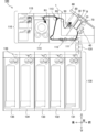
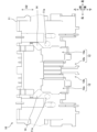
- FIG. 1 is a left side view showing the internal configuration of the automated transaction device 100.
- the up-down, front-back, and left-right directions shown in FIG. 1 and in FIGS. 2A to 9 described below are merely examples in which the customer side of the automated transaction device 100 is the front direction, but for example, the up-down direction is the vertical direction, and the front-back and left-right directions are the horizontal directions.
- the automated transaction device 100 shown in FIG. 1 is, for example, an ATM, a BRU (Bill Recycle Unit), a CD (Cash Dispenser), or a TCR (Teller Cash Recycler), and comprises a main body 110, an intermediate transport unit 120, and a storage unit 130.
- the main body 110 and the storage unit 130 are disposed in different spaces via a partition (not shown), and the intermediate transport unit 120 transports banknote B (see FIG. 2A) so that it passes through the partition.
- This banknote B is an example of a paper sheet.
- the main body 110 has a banknote deposit/withdrawal unit 1, transport units 111 and 113, a classification unit 112, a temporary holding unit 114, and a reject unit 115.
- the banknote deposit/withdrawal unit 1 has a stage 10, a roof 20, a pusher 30, an intake transport unit 40, an exhaust transport unit 50, a front panel 60, a panel shutter 70, and a first contact unit 80 (see FIG. 3A). Note that the banknote deposit/withdrawal unit 1 alone can be considered as an example of a paper sheet handling device.
- the stage 10, roof 20, pusher 30, intake transport section 40, and first contact section 80 will be described later with reference to Figures 3A to 3C and 4 to 9.
- the intake transport section 40 transports banknotes B inserted between the stage 10 and pusher 30, thereby taking them into the automated transaction device 100.
- the discharge and conveying section 50 discharges the banknotes B between the roof 20 and the pusher 30.
- the front panel 60 is disposed at an incline in both the vertical and horizontal directions on the upper front surface of the automated transaction device 100, so that the higher it goes, the further back it is located.
- the front panel 60 is provided with a deposit/withdrawal port 61.
- the panel shutter 70 releasably closes the loading/unloading port 61. Note that in FIG. 1, the panel shutter 70 in the open state is shown by a solid line, and the panel shutter 70 in the closed state is shown by a dotted line.
- the transport unit 111 transports banknotes B from the banknote deposit/withdrawal unit 1 to the classification unit 112, and also transports banknotes B between the classification unit 112 and the intermediate transport unit 120.
- the authentication unit 112 determines the authenticity, dirt, bent corners, etc. of banknote B.
- the transport unit 113 transports banknotes B between the classification unit 112 and the temporary holding unit 114, and also transports banknotes B from the classification unit 112 to the banknote deposit/withdrawal unit 1.
- the temporary holding unit 114 temporarily stores banknotes B that are inserted into the banknote deposit/withdrawal unit 1 and are determined to be normal by the validator 112.
- the reject unit 115 stores banknotes B that are determined to be abnormal by the validator 112 and will not be returned.
- the intermediate transport unit 120 transports banknotes B between the main body unit 110 and the storage unit 130.
- the storage unit 130 is disposed below the main body unit 110 and has multiple banknote storage cassettes 131, 132, 133, 134, and 135, and a storage and transport unit 136.
- the multiple banknote storage cassettes 131 to 135 store, for example, banknotes B of different denominations.
- the banknote storage cassettes 131 to 135 are capable of discharging the stored banknotes B. Therefore, the banknotes B stored in the banknote storage cassettes 131 to 135 can be used for withdrawal.
- the storage and transport section 136 transports banknotes B between the intermediate transport section 120 and each of the banknote storage cassettes 131 to 135.
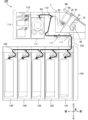
- Figures 2A to 2C are explanatory diagrams for explaining transport paths R1 to R4 for banknotes B in the automated transaction device 100.
- banknotes B inserted into the banknote deposit/withdrawal unit 1 are transported to the classification unit 112 by the take-in transport unit 40 and the transport unit 111.
- Banknotes B that are determined to be normal by the classification unit 112 are transported to the temporary holding unit 114 by the transport unit 113.
- banknotes B (such as counterfeit banknotes) that are determined to be abnormal by the validation unit 112 are returned to the banknote deposit/withdrawal unit 1 by the transport unit 113 and the discharge transport unit 50.
- the banknotes B temporarily stored in the temporary holding section 114 are transported to each of the banknote storage cassettes 131 to 135 by the transport section 113, the validation section 112, the transport section 111, the intermediate transport section 120, and the storage transport section 136.
- the banknotes B stored in each banknote storage cassette 131 to 135 are discharged to the banknote deposit/withdrawal unit 1 by the storage transport unit 136, the intermediate transport unit 120, the transport unit 111, the validation unit 112, the transport unit 113, and the discharge transport unit 50.
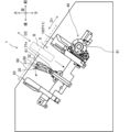
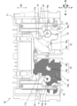
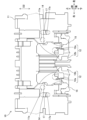
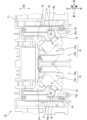
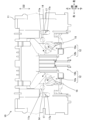
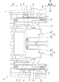
- FIGS. 3A to 3C are explanatory diagrams for explaining the deposit operation of the banknote deposit/withdrawal unit 1.
- FIG. 4 shows the stage 10 (with the first shutter 14 and the second shutter 15 closed) as viewed from the IV direction in FIG. 3B.
- FIG. 5 shows the stage 10 (with the first shutter 14 and the second shutter 15 closed) viewed from the opposite direction to the IV direction in FIG. 3B.
- Figure 6 shows the stage 10 (with the first shutter 14 and the second shutter 15 in the middle of opening and closing) viewed from the same direction as Figure 4.
- Figure 7 shows the stage 10 (with the first shutter 14 and the second shutter 15 in the middle of opening and closing) viewed from the same direction as Figure 5.
- Figure 8 shows the stage 10 (with the first shutter 14 and the second shutter 15 open) as viewed from the VIII direction in Figure 3C.
- Figure 9 shows the stage 10 (with the first shutter 14 and the second shutter 15 open) viewed from the opposite direction to direction VIII in Figure 3C.
- the stage 10 and the roof 20 are arranged to face each other across the insertion space S.
- Banknotes B are inserted into this insertion space S through an insertion/removal opening 61 in the front panel 60, which is indicated by a two-dot chain line in FIGS. 3A to 3C.
- the stage 10 and roof 20 are arranged parallel to the insertion/removal direction D2 in which banknotes B are inserted and removed, and are tilted vertically and horizontally so that they are positioned higher as they move forward. Therefore, the opposing direction D1 in which the stage 10 and roof 20 face each other is perpendicular to the insertion/removal direction D2, and is tilted vertically and horizontally so that they are positioned higher as they move rearward.
- the stage 10 has a stage body 11, two openings 12, two interlocking gears 13 (see FIG. 3B), two first shutters 14, two second shutters 15, two shutter gears 16, two guide racks 17, and two rotation center shafts 18.
- two of each of the openings 12, first shutters 14, second shutters 15, shutter gears 16, guide racks 17, and rotation center shafts 18 are arranged symmetrically.
- only one of the two symmetrical members is used as an example, and a description of the other is omitted as appropriate, but the two symmetrical members can be similar except that they are symmetrical.
- the stage 10 is arranged to be movable in the opposing direction D1 in which the stage 10 and the roof 20 face each other between an insertion position P11 (see Figures 3A and 3B) when a banknote B is inserted, and a transport position P12 (see Figure 3C) when the banknote B is transported by the pick roller 41.
- the stage 10 is an example of a first opposing portion.
- the stage body 11 is provided with a sensor hole 11a.
- This sensor hole 11a transmits detection light (not shown) that is irradiated parallel to the opposing direction D1 of the stage 10 and the roof 20 to detect the banknote B in the input space S.
- the stage body 11 has two openings 12 that are penetrated by two pick rollers 41 of the take-in transport section 40 described below.
- Each of the two openings 12 includes a first opening area 12a that is penetrated by the pick rollers 41, and a second opening area 12b that is located below the first opening area 12a and is separated from the first opening area 12a, for example.
- each of the two first shutters 14 releasably covers the first opening region 12a
- each of the two second shutters 15 releasably covers the second opening region 12b. Note that in order to show the shapes of the first shutter 14 and the second shutter 15, the first shutter 14 and the second shutter 15 on the left side of Figure 4 are shown with hatched areas that face different directions.
- the first shutter 14 and the second shutter 15 open and close by rotating about a common central axis of rotation 18 (parallel to the opposing direction D1 described above).
- the first shutter 14 and the second shutter 15 spread out in a fan shape, and the rotation angle of the second shutter 15 when opening and closing is larger than the rotation angle of the first shutter 14 when opening and closing.
- the first shutter 14 and the second shutter 15 are arranged to overlap each other above the rotation axis 18 in the open state, i.e., with the opening 12 open.
- the first shutter 14 and the second shutter 15 are positioned so as not to block the sensor transmission hole 11a in both the closed state shown in FIG. 4 and FIG. 5 and the open state shown in FIG. 8 and FIG. 9.
- the second shutter 15 is positioned so as not to block the first opening area 12a that was blocked by the first shutter 14 in the open state.
- the first shutter 14 is positioned so as not to block the second opening area 12b that was blocked by the second shutter 15 in the open state.
- the first shutter 14 is provided with a support pin 14a that extends parallel to the central axis of rotation 18.
- This support pin 14a is an example of a support portion that supports the shutter gear 16.
- This support portion is not limited to the support pin 14a, but may be a through hole into which a central axis provided on the shutter gear 16 is inserted to support the shutter gear 16.
- the shutter gear 16 Since the shutter gear 16 is supported by the support pin 14a of the first shutter 14, it rotates (moves) integrally with the first shutter 14 around the central axis of rotation 18.
- the shutter gear 16 meshes with the teeth 17a (see FIG. 5) of the guide rack 17 (see FIG. 4) and rotates while being guided by the guide rack 17.
- the guide rack 17 meshes with the shutter gear 16, which rotates integrally with the first shutter 14, at the teeth 17a, thereby guiding the shutter gear 16 as it rotates around the support pin 14a.
- the second shutter 15 has teeth 15a that mesh with the shutter gear 16, and opens and closes by rotating around the support pin 14a of the shutter gear 16. That is, the first shutter 14 rotates, the shutter gear 16 supported by the support pin 14a of the first shutter 14 rotates while being guided along the teeth 17a of the guide rack 17, and the second shutter 15 that meshes with the shutter gear 16 also rotates.
- the rotation of the first shutter 14 is transmitted through an interlocking mechanism (not shown) by the rotation of two interlocking gears 13 (only one is shown because they are overlapping) shown in FIG. 3B.
- the interlocking gears 13 are provided, for example, at the left and right ends of the lower end of the stage 10 (stage body 11).
- the two interlocking gears 13 rotate while meshing with two interlocking racks 42 (only one is shown because they are overlapping) of the take-in transport section 40 described later when the stage 10 moves from the input position P11 shown in FIGS. 3A and 3B to the transport position P12 shown in FIG. 3C. That is, the first shutter 14 rotates from a position blocking the first opening area 12a as shown in FIG.
- the two interlocking gears 13 of the stage 10 are an example of a shutter opening/closing unit that the stage 10 has.
- the two interlocking racks 42 of the intake transport unit 40 are an example of a shutter opening/closing unit that the intake transport unit 40 has.
- the shutter opening/closing unit that opens and closes the first shutter 14 and the second shutter 15 may be an actuator such as a motor that rotates one of the first shutter 14 and the second shutter 15 (the other of the first shutter 14 and the second shutter 15 also rotates in conjunction with the first shutter 14), or two (multiple) actuators such as motors that drive the first shutter 14 and the second shutter 15.
- the opening and closing directions of the first shutter 14 and the second shutter 15 are not limited to the rotational direction, but may be linear directions such as vertical and horizontal directions.
- Two first opening areas 12a are provided to match the number of pick rollers 41, but there may be one or three or more. Similarly, there may be one or three or more second opening areas 12b.
- the number of first shutters 14 may be less than the number of first opening areas 12a.
- the number of second shutters 15 may be less than the number of second opening areas 12b.
- the roof 20 shown in Figures 3A to 3C can move in the facing direction D1, and although not shown, moves toward the stage 10 when banknotes B are dispensed.
- the roof 20 is an example of a second facing part.
- the pusher 30 is an example of a partition disposed between the stage 10 and the roof 20 and capable of moving in the opposing direction D1 between the stage 10 and the roof 20.
- the pusher 30 forms an insertion space S between the stage 10 and the roof 20, into which banknotes B are inserted from the insertion/removal opening 61.
- the pusher 30 also forms an extraction space between the roof 20 and the stage 10, into which banknotes B are removed from the insertion/removal opening 61.
- the pusher 30 also has a movable member 31 that is provided at the tip on the loading/unloading port 61 side and can move to both the roof 20 side (see FIG. 3A) and the stage 10 side.
- This movable member 31 may be provided, for example, only in a portion near the center of the pusher 30 in the left-right direction that intersects the opposing direction D1 and the loading/unloading direction D2.
- the movable member 31 is supported so as to be rotatable around a rotation axis 32.
- the movable member 31 may be biased by an elastic body such as a torsion spring so as to maintain a position parallel to the stage 10 and roof 20.
- a pressed protrusion 31a that protrudes downward (toward the stage 10) is provided on the movable member 31 on the opposite side of the rotation axis 32 from the loading/unloading opening 61.
- the take-in transport section 40 shown in FIG. 3B has a pick roller 41 and an interlocking rack 42. Although not shown in FIG. 3B, there are two pick rollers 41 and two interlocking racks 42.
- the two pick rollers 41 transport the banknotes B inserted into the input space S (see FIG. 3A) while protruding from the two first opening areas 12a (see FIG. 8) of the stage 10 toward the input space S.
- the take-in transport unit 40 is an example of a transport unit that transports the banknotes B inserted into the input space S while protruding from the opening 12 (first opening area 12a) of the stage 10 toward the input space S.
- the two interlocking racks 42 mesh with the two interlocking gears 13 of the stage 10 as described above.
- the take-in transport section 40 may be disposed on the roof 20 side instead of the stage 10 side. In that case, the opening 12, the first shutter 14, the second shutter 15, etc. are disposed on the roof 20 instead of the stage 10.
- the stage 10 is located below the input space S, so that foreign objects are more likely to enter the inside of the banknote deposit/withdrawal unit 1 through the opening 12 of the stage 10 compared to when an opening is provided in the roof 20.
- the take-in transport unit 40 may be disposed on the stage 10 side rather than the roof 20 side, and the banknote B may be transported in a state where it protrudes from the opening 12 of the stage 10 toward the input space S. In this case, foreign objects are particularly likely to fall from the opening 12 into the inside of the banknote deposit/withdrawal unit 1.
- the first shutter 14 that releasably closes the first opening area 12a and the second shutter 15 that releasably closes the second opening area 12b are disposed, so that it is possible to prevent foreign objects from falling into the inside of the banknote deposit/withdrawal unit 1 from the opening 12 (the first opening area 12a and the second opening area 12b).
- a bill receiver (not shown) is disposed to support the bottom of the bill B. This bill receiver has a gap through which foreign objects can fall, and foreign objects that fall through this gap can be stored in the foreign object receiver (not shown).
- the first contact portion 80 is provided behind the insertion/removal opening 61 and is a protrusion that protrudes downward from the back side of the front panel 60.
- the pusher 30 forms an insertion space S between it and the stage 10.
- the movable member 31 comes into contact with the first contact portion 80 and is pressed against the elastic force of the elastic body, so that it moves so as to tilt towards the roof 20.
- the movable member 31 may also move so as to tilt towards the roof 20, for example, by the power of a driving means (not shown).
- the pusher 30 After the pusher 30 has finished inserting the banknote B, it moves toward the stage 10 and sandwiches the banknote B between the pusher 30 and the stage 10. Then, as shown in FIG. 3C, the stage 10 moves together with the pusher 30 diagonally downward toward the front to the transport position P12 on the side of the intake transport section 40. As a result, as described above, the interlocking gear 13 and the interlocking rack 42 mesh, the first shutter 14 and the second shutter 15 of the stage 10 open, and the two openings 12 (the first opening area 12a and the second opening area 12b) are exposed. Then, with the two pick rollers 41 of the intake transport section 40 protruding from the two first opening areas 12a, the banknote B is transported by the intake transport section 40 toward the transport section 111 shown in FIG. 1.
- the number of banknotes B to be dispensed is transported between the pusher 30 and the roof 20 by the discharge transport section 50 shown in FIG. 1, and then the pusher 30 moves together with the roof 20 towards the stage 10.
- the pusher 30 forms a removal space for banknotes B between itself and the roof 20.
- the movable member 31 moves so as to tilt towards the stage 10 as the pressed protrusion 31a comes into contact with the stage 10 and is pressed against the elastic force of the elastic body. This makes it easier for customers to remove banknotes B, as the removal space (between the pusher 30 and the roof 20) becomes wider towards the insertion/removal opening 61.
- the stage 10 functions as an example of a second contact portion that moves the movable member 31 toward the stage 10 by contacting the movable member 31.
- the movable member 31 may move so as to tilt toward the stage 10, for example, by the power of a driving means (not shown).
- the movable member 31 may also move so as to tilt toward the stage 10 by contacting a second contact portion other than the stage 10.
- the movable member 31 may also contact the stage 10 (second contact portion) at a portion other than the pressed protrusion 31a.
- the bill receiver (not shown) located at the bottom of the insertion space S moves to the insertion/removal opening 61 side, and the bill B is lifted up toward the customer. The customer then removes the bill B.
- the automated transaction device 100 which is an example of a paper sheet handling device, includes a stage 10 (an example of a first opposing portion) and a roof 20 (an example of a second opposing portion) that are arranged to face each other across an input space S into which banknotes B (an example of paper sheets) are inserted, and an intake transport section 40 (an example of a transport section) that transports banknotes B inserted into the input space S while protruding from an opening 12 of the stage 10 toward the input space S.
- a stage 10 an example of a first opposing portion
- a roof 20 an example of a second opposing portion
- an intake transport section 40 an example of a transport section
- the stage 10 has a first shutter 14 that releasably covers a first opening area 12a of the opening 12, and a second shutter 15 that releasably covers a second opening area 12b of the opening 12 that is different from the first opening area 12a.
- the first shutter 14 and the second shutter 15 are arranged to overlap each other when the opening 12 is open.
- the first shutter 14 that blocks the first opening area 12a is disposed, thereby preventing foreign objects from entering the inside of the banknote deposit and withdrawal unit 1 through the first opening area 12a from the input space S for the banknote B.
- the second shutter 15 can block the second opening area 12b that cannot be blocked by the first shutter 14, thereby preventing foreign objects from entering the inside of the banknote deposit and withdrawal unit 1 through the second opening area 12b.
- first shutter 14 and the second shutter 15 overlap each other with the opening 12 (first opening area 12a and second opening area 12b) open, so they can retreat to a narrow area of the stage body 11 that avoids the opening 12 and the sensor transmission hole 11a. Therefore, the first shutter 14 and the second shutter 15 can be formed to a size that covers most of the opening 12, so that foreign objects can be sufficiently prevented from entering the inside of the banknote deposit and withdrawal unit 1 through the opening 12.
- this embodiment can prevent foreign objects from entering the insertion space S into which the banknotes B (paper sheets) are inserted.
- first shutter 14 and the second shutter 15 open and close by rotating about a common central axis of rotation 18.
- the shutter gear 16 is supported by a support pin 14a (an example of a support portion) of the first shutter 14 that extends parallel to the rotation center axis 18, and rotates integrally with the first shutter 14 around the rotation center axis 18, while rotating independently of the first shutter 14 around the support pin 14a.
- the second shutter 15 has teeth 15a that mesh with the shutter gear 16, and opens and closes by rotating in conjunction with the rotation of the shutter gear 16 around the support pin 14a.
- the second shutter 15 to be rotated using the shutter gear 16 that rotates integrally with the first shutter 14, further simplifying the configuration for opening and closing the first shutter 14 and the second shutter 15. Furthermore, by using the shutter gear 16, the opening and closing angle (rotation angle) of the second shutter 15 can be adjusted by the trajectory of the shutter gear 16 (the position of the shutter gear 16 on the stage body 11), the size of the shutter gear 16, etc., allowing the second shutter 15 to be flexibly positioned.
- the guide rack 17 has teeth 17a that mesh with the shutter gear 16 that rotates integrally with the first shutter 14, thereby guiding the shutter gear 16 while rotating it around the support pin 14a as the center of rotation.
- the intake transport section 40 (an example of a transport section) protrudes from the first opening area 12a of the opening 12 toward the input space S, and the second opening area 12b of the opening 12 is located below the first opening area 12a.
- the second opening area 12b is located lower than the first opening area 12a, which is for passing through the intake conveying section 40, and can therefore be considered an area into which foreign objects moving downward due to gravity can easily enter. By blocking this second opening area 12b with the second shutter 15, it is possible to more reliably prevent foreign objects from entering from the input space S.
- the present invention is not limited to the above-described embodiment, but can be embodied by modifying the components.
- various inventions can be formed by appropriately combining the multiple components disclosed in the present embodiment. In this way, various modifications and applications of the invention are possible within the scope of the spirit of the invention.
Landscapes
- Physics & Mathematics (AREA)
- General Physics & Mathematics (AREA)
- Sheets, Magazines, And Separation Thereof (AREA)
Priority Applications (2)
| Application Number | Priority Date | Filing Date | Title |
|---|---|---|---|
| PCT/JP2023/005903 WO2024176282A1 (ja) | 2023-02-20 | 2023-02-20 | 紙葉類取扱装置 |
| JP2025501914A JPWO2024176282A1 (enExample) | 2023-02-20 | 2023-02-20 |
Applications Claiming Priority (1)
| Application Number | Priority Date | Filing Date | Title |
|---|---|---|---|
| PCT/JP2023/005903 WO2024176282A1 (ja) | 2023-02-20 | 2023-02-20 | 紙葉類取扱装置 |
Publications (1)
| Publication Number | Publication Date |
|---|---|
| WO2024176282A1 true WO2024176282A1 (ja) | 2024-08-29 |
Family
ID=92500584
Family Applications (1)
| Application Number | Title | Priority Date | Filing Date |
|---|---|---|---|
| PCT/JP2023/005903 Ceased WO2024176282A1 (ja) | 2023-02-20 | 2023-02-20 | 紙葉類取扱装置 |
Country Status (2)
| Country | Link |
|---|---|
| JP (1) | JPWO2024176282A1 (enExample) |
| WO (1) | WO2024176282A1 (enExample) |
Citations (5)
| Publication number | Priority date | Publication date | Assignee | Title |
|---|---|---|---|---|
| JP2006004039A (ja) * | 2004-06-16 | 2006-01-05 | Hitachi Omron Terminal Solutions Corp | 紙幣処理装置 |
| JP2010108159A (ja) * | 2008-10-29 | 2010-05-13 | Oki Electric Ind Co Ltd | 紙幣入出金機構 |
| WO2014103531A1 (ja) * | 2012-12-28 | 2014-07-03 | 沖電気工業株式会社 | 自動取引装置 |
| WO2021166259A1 (ja) * | 2020-02-21 | 2021-08-26 | 富士通フロンテック株式会社 | 紙葉類取扱装置 |
| WO2022176178A1 (ja) * | 2021-02-22 | 2022-08-25 | 富士通フロンテック株式会社 | 紙葉類取扱装置 |
-
2023
- 2023-02-20 JP JP2025501914A patent/JPWO2024176282A1/ja active Pending
- 2023-02-20 WO PCT/JP2023/005903 patent/WO2024176282A1/ja not_active Ceased
Patent Citations (5)
| Publication number | Priority date | Publication date | Assignee | Title |
|---|---|---|---|---|
| JP2006004039A (ja) * | 2004-06-16 | 2006-01-05 | Hitachi Omron Terminal Solutions Corp | 紙幣処理装置 |
| JP2010108159A (ja) * | 2008-10-29 | 2010-05-13 | Oki Electric Ind Co Ltd | 紙幣入出金機構 |
| WO2014103531A1 (ja) * | 2012-12-28 | 2014-07-03 | 沖電気工業株式会社 | 自動取引装置 |
| WO2021166259A1 (ja) * | 2020-02-21 | 2021-08-26 | 富士通フロンテック株式会社 | 紙葉類取扱装置 |
| WO2022176178A1 (ja) * | 2021-02-22 | 2022-08-25 | 富士通フロンテック株式会社 | 紙葉類取扱装置 |
Also Published As
| Publication number | Publication date |
|---|---|
| JPWO2024176282A1 (enExample) | 2024-08-29 |
Similar Documents
| Publication | Publication Date | Title |
|---|---|---|
| US6942207B2 (en) | Bill receiving/dispensing box | |
| JP5724652B2 (ja) | 媒体処理装置 | |
| JP5500190B2 (ja) | 媒体取引装置 | |
| JP5950839B2 (ja) | 搬送制御装置 | |
| CN103650008A (zh) | 介质处理装置 | |
| US9611117B2 (en) | Medium processing device and medium transaction device | |
| JP5553134B2 (ja) | 媒体取引装置 | |
| US20220392291A1 (en) | Paper sheet handling apparatus | |
| JP5615391B2 (ja) | 紙葉還流庫 | |
| JP6565343B2 (ja) | 駆動力伝達装置及び媒体処理装置 | |
| US12444262B2 (en) | Paper sheet handling apparatus | |
| WO2024176282A1 (ja) | 紙葉類取扱装置 | |
| KR101016245B1 (ko) | 금융자동화기기의 출금장치 | |
| JP7253107B2 (ja) | 紙葉類取扱装置 | |
| JP6866118B2 (ja) | 紙葉類処理装置 | |
| JP7253108B2 (ja) | 紙葉類取扱装置 | |
| JP6417927B2 (ja) | 媒体処理装置 | |
| JP2018097634A (ja) | 媒体収納庫及び媒体取引装置 | |
| JP6702040B2 (ja) | 媒体処理装置 | |
| JP5935624B2 (ja) | シャッタ装置 | |
| KR200389004Y1 (ko) | 금융자동화기기의 출금장치 | |
| JP2002279482A (ja) | 硬貨入金口 | |
| WO2022176081A1 (ja) | 紙葉類取扱装置 | |
| JP2025174119A (ja) | 硬貨繰出装置及び硬貨処理装置 | |
| KR101016508B1 (ko) | 금융자동화기기의 출금장치 |
Legal Events
| Date | Code | Title | Description |
|---|---|---|---|
| 121 | Ep: the epo has been informed by wipo that ep was designated in this application |
Ref document number: 23923938 Country of ref document: EP Kind code of ref document: A1 |
|
| WWE | Wipo information: entry into national phase |
Ref document number: 2025501914 Country of ref document: JP |
|
| NENP | Non-entry into the national phase |
Ref country code: DE |