WO2024166694A1 - 円筒部材の製造方法及び金型 - Google Patents
円筒部材の製造方法及び金型 Download PDFInfo
- Publication number
- WO2024166694A1 WO2024166694A1 PCT/JP2024/002186 JP2024002186W WO2024166694A1 WO 2024166694 A1 WO2024166694 A1 WO 2024166694A1 JP 2024002186 W JP2024002186 W JP 2024002186W WO 2024166694 A1 WO2024166694 A1 WO 2024166694A1
- Authority
- WO
- WIPO (PCT)
- Prior art keywords
- workpiece
- upper die
- die
- mold
- processing surface
- Prior art date
- Legal status (The legal status is an assumption and is not a legal conclusion. Google has not performed a legal analysis and makes no representation as to the accuracy of the status listed.)
- Ceased
Links
Images




Classifications
-
- B—PERFORMING OPERATIONS; TRANSPORTING
- B21—MECHANICAL METAL-WORKING WITHOUT ESSENTIALLY REMOVING MATERIAL; PUNCHING METAL
- B21D—WORKING OR PROCESSING OF SHEET METAL OR METAL TUBES, RODS OR PROFILES WITHOUT ESSENTIALLY REMOVING MATERIAL; PUNCHING METAL
- B21D19/00—Flanging or other edge treatment, e.g. of tubes
- B21D19/08—Flanging or other edge treatment, e.g. of tubes by single or successive action of pressing tools, e.g. vice jaws
- B21D19/10—Flanging or other edge treatment, e.g. of tubes by single or successive action of pressing tools, e.g. vice jaws working inwardly
-
- H—ELECTRICITY
- H01—ELECTRIC ELEMENTS
- H01M—PROCESSES OR MEANS, e.g. BATTERIES, FOR THE DIRECT CONVERSION OF CHEMICAL ENERGY INTO ELECTRICAL ENERGY
- H01M50/00—Constructional details or processes of manufacture of the non-active parts of electrochemical cells other than fuel cells, e.g. hybrid cells
- H01M50/10—Primary casings; Jackets or wrappings
- H01M50/102—Primary casings; Jackets or wrappings characterised by their shape or physical structure
- H01M50/107—Primary casings; Jackets or wrappings characterised by their shape or physical structure having curved cross-section, e.g. round or elliptic
-
- B—PERFORMING OPERATIONS; TRANSPORTING
- B21—MECHANICAL METAL-WORKING WITHOUT ESSENTIALLY REMOVING MATERIAL; PUNCHING METAL
- B21D—WORKING OR PROCESSING OF SHEET METAL OR METAL TUBES, RODS OR PROFILES WITHOUT ESSENTIALLY REMOVING MATERIAL; PUNCHING METAL
- B21D17/00—Forming single grooves in sheet metal or tubular or hollow articles
- B21D17/02—Forming single grooves in sheet metal or tubular or hollow articles by pressing
-
- B—PERFORMING OPERATIONS; TRANSPORTING
- B21—MECHANICAL METAL-WORKING WITHOUT ESSENTIALLY REMOVING MATERIAL; PUNCHING METAL
- B21D—WORKING OR PROCESSING OF SHEET METAL OR METAL TUBES, RODS OR PROFILES WITHOUT ESSENTIALLY REMOVING MATERIAL; PUNCHING METAL
- B21D19/00—Flanging or other edge treatment, e.g. of tubes
- B21D19/08—Flanging or other edge treatment, e.g. of tubes by single or successive action of pressing tools, e.g. vice jaws
-
- B—PERFORMING OPERATIONS; TRANSPORTING
- B21—MECHANICAL METAL-WORKING WITHOUT ESSENTIALLY REMOVING MATERIAL; PUNCHING METAL
- B21D—WORKING OR PROCESSING OF SHEET METAL OR METAL TUBES, RODS OR PROFILES WITHOUT ESSENTIALLY REMOVING MATERIAL; PUNCHING METAL
- B21D19/00—Flanging or other edge treatment, e.g. of tubes
- B21D19/16—Reverse flanging of tube ends
-
- B—PERFORMING OPERATIONS; TRANSPORTING
- B21—MECHANICAL METAL-WORKING WITHOUT ESSENTIALLY REMOVING MATERIAL; PUNCHING METAL
- B21D—WORKING OR PROCESSING OF SHEET METAL OR METAL TUBES, RODS OR PROFILES WITHOUT ESSENTIALLY REMOVING MATERIAL; PUNCHING METAL
- B21D37/00—Tools as parts of machines covered by this subclass
- B21D37/08—Dies with different parts for several steps in a process
-
- B—PERFORMING OPERATIONS; TRANSPORTING
- B21—MECHANICAL METAL-WORKING WITHOUT ESSENTIALLY REMOVING MATERIAL; PUNCHING METAL
- B21D—WORKING OR PROCESSING OF SHEET METAL OR METAL TUBES, RODS OR PROFILES WITHOUT ESSENTIALLY REMOVING MATERIAL; PUNCHING METAL
- B21D39/00—Application of procedures in order to connect objects or parts, e.g. coating with sheet metal otherwise than by plating; Tube expanders
-
- B—PERFORMING OPERATIONS; TRANSPORTING
- B21—MECHANICAL METAL-WORKING WITHOUT ESSENTIALLY REMOVING MATERIAL; PUNCHING METAL
- B21D—WORKING OR PROCESSING OF SHEET METAL OR METAL TUBES, RODS OR PROFILES WITHOUT ESSENTIALLY REMOVING MATERIAL; PUNCHING METAL
- B21D41/00—Application of procedures in order to alter the diameter of tube ends
- B21D41/04—Reducing; Closing
-
- B—PERFORMING OPERATIONS; TRANSPORTING
- B21—MECHANICAL METAL-WORKING WITHOUT ESSENTIALLY REMOVING MATERIAL; PUNCHING METAL
- B21D—WORKING OR PROCESSING OF SHEET METAL OR METAL TUBES, RODS OR PROFILES WITHOUT ESSENTIALLY REMOVING MATERIAL; PUNCHING METAL
- B21D51/00—Making hollow objects
- B21D51/16—Making hollow objects characterised by the use of the objects
- B21D51/26—Making hollow objects characterised by the use of the objects cans or tins; Closing same in a permanent manner
- B21D51/2615—Edge treatment of cans or tins
- B21D51/263—Flanging
-
- H—ELECTRICITY
- H01—ELECTRIC ELEMENTS
- H01M—PROCESSES OR MEANS, e.g. BATTERIES, FOR THE DIRECT CONVERSION OF CHEMICAL ENERGY INTO ELECTRICAL ENERGY
- H01M50/00—Constructional details or processes of manufacture of the non-active parts of electrochemical cells other than fuel cells, e.g. hybrid cells
- H01M50/10—Primary casings; Jackets or wrappings
- H01M50/147—Lids or covers
- H01M50/148—Lids or covers characterised by their shape
- H01M50/152—Lids or covers characterised by their shape for cells having curved cross-section, e.g. round or elliptic
-
- H—ELECTRICITY
- H01—ELECTRIC ELEMENTS
- H01M—PROCESSES OR MEANS, e.g. BATTERIES, FOR THE DIRECT CONVERSION OF CHEMICAL ENERGY INTO ELECTRICAL ENERGY
- H01M50/00—Constructional details or processes of manufacture of the non-active parts of electrochemical cells other than fuel cells, e.g. hybrid cells
- H01M50/10—Primary casings; Jackets or wrappings
- H01M50/147—Lids or covers
- H01M50/166—Lids or covers characterised by the methods of assembling casings with lids
- H01M50/167—Lids or covers characterised by the methods of assembling casings with lids by crimping
-
- Y—GENERAL TAGGING OF NEW TECHNOLOGICAL DEVELOPMENTS; GENERAL TAGGING OF CROSS-SECTIONAL TECHNOLOGIES SPANNING OVER SEVERAL SECTIONS OF THE IPC; TECHNICAL SUBJECTS COVERED BY FORMER USPC CROSS-REFERENCE ART COLLECTIONS [XRACs] AND DIGESTS
- Y02—TECHNOLOGIES OR APPLICATIONS FOR MITIGATION OR ADAPTATION AGAINST CLIMATE CHANGE
- Y02E—REDUCTION OF GREENHOUSE GAS [GHG] EMISSIONS, RELATED TO ENERGY GENERATION, TRANSMISSION OR DISTRIBUTION
- Y02E60/00—Enabling technologies; Technologies with a potential or indirect contribution to GHG emissions mitigation
- Y02E60/10—Energy storage using batteries
Definitions
- This disclosure relates to a method for manufacturing a cylindrical member.
- This disclosure also relates to a die, and more specifically, to a die for bending the end of a cylindrical workpiece toward the inner circumference.
- the open end of a cylindrical workpiece may be bent inward.
- the open end can be used to secure a component placed inside the cylindrical component.
- This type of processing is generally called bending and crimping.
- Patent Document 1 discloses a bending and crimping process in which the open end of a cylindrical workpiece is curled in three steps.
- a curl roller is pressed against the open end of the workpiece while rotating, forming a curled portion at the open end.
- a collet is used to grasp the curled portion of the workpiece, and the curled portion is squeezed.
- a crimping die is pressed from above against the innermost end of the curled portion that has been slightly raised by the secondary curling process, and the innermost end is bent downward.
- Patent Document 1 the open end of the workpiece is bent inwardly by a three-step curling process.
- the driving direction of the tool that processes the open end of the workpiece is different for each curling process, making the process of bending the open end of the workpiece complicated.
- the opening end of the workpiece is formed into a curled shape as a whole by undergoing three curling processes.
- the specifications of the cylindrical part to be manufactured require that at least a portion of the opening end of the workpiece that is bent toward the inner circumference be straight, the technology described in Patent Document 1 cannot form such a shape.
- the objective of this disclosure is to provide a method for manufacturing a cylindrical member that can easily impart a bend to the end of a workpiece and can form at least a portion of the end bent toward the inner circumference into a straight line.
- the manufacturing method of the cylindrical member according to the present disclosure includes a preparation step of preparing a workpiece having a cylindrical shape, and a bending step of bending an end of the workpiece in the axial direction toward the inner circumference of the workpiece using a lower die placed in the workpiece and an upper die that approaches the workpiece relatively along the axial direction of the workpiece.
- the upper die includes a concave machining surface.
- the machining surface is provided at a position corresponding to the end of the workpiece on the surface of the upper die that faces the workpiece in the axial direction.
- the machining surface includes a first portion and a second portion.
- the first portion when viewed in a cross section including the central axis of the workpiece, extends to the opposite side of the workpiece in the axial direction of the workpiece and toward the inner circumference of the workpiece.
- the first portion guides the end of the workpiece to the inner circumference of the workpiece in the bending step.
- the second portion is continuous with the first portion.
- the second portion When viewed in a cross section including the central axis of the workpiece, the second portion extends from the first portion toward the inner circumference of the workpiece and has a straight shape.
- the second part clamps the end of the workpiece together with the lower die during the bending process.
- the angle ⁇ between the extension line of the second part and the extension line of the end of the workpiece before the start of the bending process is 45° or more and less than 90°.
- Another method for manufacturing a cylindrical member according to the present disclosure includes a preparation step of preparing a workpiece having a cylindrical shape, and a bending step of bending an end of the workpiece in the axial direction toward the inner circumference of the workpiece using a lower die placed in the workpiece and an upper die that approaches the workpiece relatively along the axial direction of the workpiece.
- the upper die includes a concave machining surface.
- the machining surface is provided at a position corresponding to the end of the workpiece on the surface of the upper die that faces the workpiece in the axial direction.
- the machining surface includes a first portion and a second portion.
- the first portion extends toward the opposite side of the workpiece in the axial direction of the workpiece and toward the inner circumference of the workpiece when viewed in a cross section including the central axis of the workpiece.
- the second portion is disposed on the inner circumference of the workpiece relative to the first portion when viewed in a cross section including the central axis of the workpiece and has a linear shape.
- the upper die includes a first upper die and a second upper die.
- the first upper die includes at least a portion of the first portion of the machining surface.
- the second upper die is separate from the first upper die.
- the second upper die is disposed on the inner periphery side of the workpiece relative to the first upper die.
- the second upper die includes at least a part of the second portion of the processing surface. In the bending process, the end of the workpiece is guided to the inner periphery side of the workpiece by the first upper die, and then the end of the workpiece is clamped between the second upper die and the lower die
- the manufacturing method for a cylindrical member according to the present disclosure allows the end of the workpiece to be easily bent. Furthermore, the manufacturing method for a cylindrical member according to the present disclosure allows at least a portion of the end of the workpiece that is bent toward the inner circumference to be formed straight.
- FIG. 1 is a perspective view of a cylindrical member manufactured by a manufacturing method according to a first embodiment.
- FIG. 2A is a schematic diagram for explaining a manufacturing method of a cylindrical member according to the first embodiment.
- FIG. 2B is a schematic view for explaining the method for manufacturing the cylindrical member according to the first embodiment.
- FIG. 2C is a schematic view for explaining the manufacturing method of the cylindrical member according to the first embodiment.
- FIG. 2D is a schematic diagram for explaining the manufacturing method of the cylindrical member according to the first embodiment.
- FIG. 3A is a schematic diagram for explaining a manufacturing method of a cylindrical member according to the second embodiment.
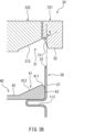
- FIG. 3B is a schematic diagram for explaining a manufacturing method of a cylindrical member according to the second embodiment.
- FIG. 3C is a schematic view for explaining a manufacturing method of a cylindrical member according to the second embodiment.
- FIG. 3D is a schematic diagram for explaining a manufacturing method of a cylindrical member according to the second embodiment.
- FIG. 4 is a schematic diagram showing a method for manufacturing a cylindrical member according to a modified example of the first embodiment.
- FIG. 5 is a schematic diagram showing a method for manufacturing a cylindrical member according to a modified example of the second embodiment.
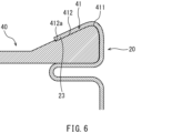
- 6A to 6C are schematic diagrams showing a method for manufacturing a cylindrical member according to a modification of each embodiment.
- the manufacturing method of the cylindrical member according to the embodiment includes a preparation step of preparing a workpiece having a cylindrical shape, and a bending step of bending an end of the workpiece in the axial direction toward the inner circumference of the workpiece using a lower die placed in the workpiece and an upper die that approaches the workpiece relatively along the axial direction of the workpiece.
- the upper die includes a concave machining surface.
- the machining surface is provided at a position corresponding to the end of the workpiece on the surface of the upper die that faces the workpiece in the axial direction.
- the machining surface includes a first portion and a second portion.
- the first portion when viewed in a cross section including the central axis of the workpiece, extends to the opposite side of the workpiece in the axial direction of the workpiece and toward the inner circumference of the workpiece.
- the first portion guides the end of the workpiece to the inner circumference of the workpiece in the bending step.
- the second portion is continuous with the first portion. When viewed in a cross section including the central axis of the workpiece, the second portion extends from the first portion toward the inner circumference of the workpiece and has a straight shape. The second part clamps the end of the workpiece together with the lower die during the bending process.
- the angle ⁇ between the extension line of the second part and the extension line of the end of the workpiece before the start of the bending process is 45° or more and less than 90° (first configuration).
- a method for manufacturing a cylindrical member includes a preparation step of preparing a workpiece having a cylindrical shape, and a bending step of bending an end of the workpiece in the axial direction toward the inner circumference of the workpiece using a lower die placed in the workpiece and an upper die that approaches the workpiece relatively along the axial direction of the workpiece.
- the upper die includes a concave machining surface.
- the machining surface is provided at a position corresponding to the end of the workpiece on the surface of the upper die that faces the workpiece in the axial direction.
- the machining surface includes a first portion and a second portion.
- the first portion extends toward the opposite side of the workpiece in the axial direction of the workpiece and toward the inner circumference of the workpiece when viewed in a cross section including the central axis of the workpiece.
- the second portion is disposed on the inner circumference of the workpiece relative to the first portion when viewed in a cross section including the central axis of the workpiece and has a linear shape.
- the upper die includes a first upper die and a second upper die.
- the first upper die includes at least a part of the first portion of the machining surface.
- the second upper die is separate from the first upper die.
- the second upper die is disposed on the inner periphery side of the workpiece relative to the first upper die.
- the second upper die includes at least a part of the second portion of the processing surface.
- the end of the workpiece is bent inwardly simply by bringing the upper die relatively close to the workpiece and the lower die placed inside the workpiece along the axial direction of the workpiece. This does not complicate the bending process, and the end of the workpiece can be easily bent.
- the machining surface of the upper die is provided with a first portion that guides the end of the workpiece toward the inner circumference, and a second portion that clamps the end of the workpiece together with the lower die.
- the second portion is disposed closer to the inner circumference of the workpiece than the first portion, and has a straight line shape when viewed in a cross section including the central axis of the workpiece.
- the angle ⁇ between the extension line of the second part of the processing surface of the upper die and the extension line of the end of the workpiece before the start of the bending process is 45° or more and less than 90°. This makes it difficult for the end of the workpiece to get caught on the boundary between the first and second parts of the processing surface when the end of the workpiece is bent inward by the upper die. This makes it possible to prevent buckling from occurring at the end of the workpiece during the bending process.
- the upper die includes a first upper die and a second upper die which are separate bodies, and after the end of the workpiece is guided to the inner circumference by the first upper die, the second upper die clamps the end of the workpiece together with the lower die.
- the first portion can have a concave curved shape when viewed in a cross section including the central axis of the workpiece (third configuration).
- the first portion may have a straight line shape when viewed in a cross section including the central axis of the workpiece (fourth configuration).
- the workpiece is made of a steel material having a tensile strength of, for example, 290 MPa or more (fifth configuration).
- the end of the workpiece may have a plate thickness of 3.0 mm or less (sixth configuration).
- the cylindrical member may be a battery having a bottomed cylindrical shape and housing an electrode body.
- the lower mold is a sealing body (seventh configuration).
- the die according to the embodiment is a die for bending the end of a cylindrical workpiece toward the inner circumference.
- the die includes an upper die and a lower die.
- the upper die has a cylindrical shape.
- One of the two axial surfaces of the upper die is provided with a concave machining surface.
- the lower die is cylindrical.
- One of the two axial surfaces of the lower die that faces the upper die when the die is in use is provided with a convex machining surface corresponding to the machining surface of the upper die.
- the machining surface of the upper die includes a first portion and a second portion.
- the first portion extends toward the opposite side of the lower die and toward the inner circumference of the upper die when viewed in a cross section including the central axes of the upper die and the lower die.
- the second portion is continuous with the first portion.
- the second portion extends from the first portion toward the inner circumference of the upper die when viewed in a cross section including the central axis and has a linear shape.
- the machining surface of the lower die includes a first portion and a second portion. On the machining surface of the lower mold, the first portion is disposed at a position corresponding to the first portion of the machining surface of the upper mold, and is continuous with the side surface of the lower mold.
- the second portion On the machining surface of the lower mold, the second portion is continuous with the first portion.
- the second portion of the machining surface of the lower mold has a shape corresponding to the second portion of the machining surface of the upper mold.
- the angle ⁇ formed by the extension line of the second portion of the machining surface of the upper mold and the extension line of the side surface of the lower mold is 45° or more and less than 90° (eighth configuration).
- a mold according to another embodiment is a mold for bending the end of a cylindrical workpiece toward the inner circumference.
- the mold includes an upper mold and a lower mold.
- the upper mold has a cylindrical shape.
- One of the two axial surfaces of the upper mold is provided with a concave machining surface.
- the lower mold is cylindrical.
- One of the two axial surfaces of the lower mold that faces the upper mold when the mold is in use is provided with a convex machining surface corresponding to the machining surface of the upper mold.
- the machining surface of the upper mold includes a first portion and a second portion.
- the first portion extends toward the opposite side of the lower mold and toward the inner circumference of the upper mold when viewed in a cross section including the central axes of the upper mold and the lower mold.
- the second portion is disposed on the inner circumference side of the upper mold relative to the first portion when viewed in a cross section including the central axis and has a linear shape.
- the machining surface of the lower mold includes a first portion and a second portion.
- the first portion is disposed at a position corresponding to the first portion of the machining surface of the upper mold and is continuous with the side of the lower mold.
- the second portion is continuous with the first portion.
- the second portion of the machining surface of the lower mold has a shape corresponding to the second portion of the machining surface of the upper mold.
- the upper mold includes a first upper mold and a second upper mold.
- the first upper mold includes at least a portion of the first portion of the machining surface of the upper mold.
- the first upper mold has an annular shape.
- the second upper mold is separate from the first upper mold.
- the second upper mold is disposed inside the first upper mold.
- the second upper mold includes at least a portion of the second portion of the machining surface of the upper mold (ninth configuration).
- First Embodiment [Cylindrical member] 1 is a perspective view showing a cylindrical member 10 manufactured by the manufacturing method according to the present embodiment.
- the cylindrical member 10 is, for example, a battery.
- the cylindrical member 10 may be a pipe, a pipe joint, or the like. In the present embodiment, an example in which the cylindrical member 10 is a battery will be described.
- the cylindrical member 10 includes a battery case 11, an electrode body 12, and a sealing body 13.
- the battery case 11 includes a peripheral wall 111, a bottom plate 112, and a bead 113.
- the peripheral wall 111 has a substantially cylindrical shape.
- the bottom plate 112 seals one axial end of the peripheral wall 111.
- the bead 113 is disposed on the other axial end side of the peripheral wall 111.
- the bead 113 is provided on the peripheral wall 111.
- the bead 113 has a shape that protrudes from the peripheral wall 111 toward the radially inward side of the peripheral wall 111.
- the bead 113 extends around the entire circumference of the peripheral wall 111 and has an annular shape.
- the electrode body 12 is housed in the battery case 11.
- the electrode body 12 is disposed between the bottom plate 112 and the bead 113 in the axial direction of the peripheral wall 111.
- the electrode body 12 is a known electrode body selected according to the type of battery. For example, if the cylindrical member 10 is a lithium ion secondary battery, the electrode body 12 is an electrode body for a lithium ion secondary battery.
- the sealing body 13 is housed in the battery case 11.
- the sealing body 13 is placed on the bead 113 inside the peripheral wall 111.
- the sealing body 13 is fixed to the battery case 11 by crimping. More specifically, the end of the peripheral wall 111 of the battery case 11 near the sealing body 13 is bent inward, thereby fixing the sealing body 13 to the battery case 11.
- the sealing body 13 is a well-known sealing body that is generally used for batteries.
- the method for manufacturing the cylindrical member 10 includes a preparation step and a bending step.
- a workpiece 20 is prepared.
- the workpiece 20 has a cylindrical shape with a bottom. That is, the workpiece 20 includes a cylindrical peripheral wall 21 and a bottom plate 22 that closes one axial end of the peripheral wall 21. The other axial end of the peripheral wall 21 is an open end.
- the workpiece 20 is the material of the battery case 11 (FIG. 1) described above.
- a bead 113 is formed on the peripheral wall 21 of the workpiece 20 before the bending step.
- the workpiece 20 is made of, for example, steel.
- the workpiece 20 may be made of plated steel or stainless steel.
- the cylindrical member 10 (FIG. 1) to be manufactured is a battery as in this embodiment, the workpiece 20 is preferably made of nickel-plated steel.
- the steel constituting the workpiece 20 may have a tensile strength of 290 MPa or more.
- the tensile strength of the steel may be 300 MPa or more, 330 MPa or more, or 350 MPa or more.
- the tensile strength of the steel may be 380 MPa or more, or 400 MPa or more.
- the workpiece 20 may be formed into a cylindrical bottomed shape by drawing a steel plate.
- the workpiece 20 does not necessarily have to be made of steel. It is sufficient that the workpiece 20 is made of a metal.
- the workpiece 20 may be made of, for example, aluminum, titanium, or copper, or an alloy of these.
- the thickness of the end of the workpiece 20 on the opening side is, for example, 3.0 mm or less.
- the workpiece 20 may have a thickness of 3.0 mm or less throughout.
- the thickness of the end of the workpiece 20 on the opening side is, for example, 0.1 mm or more.
- the workpiece 20 may have a thickness of 0.1 mm or more throughout.
- the bending process is a process of bending the end of the workpiece 20 on the opening side toward the inner circumference of the workpiece 20.
- the end of the workpiece 20 is bent using a die including an upper die 30 and a lower die 40.
- the workpiece 20, the upper die 30, and the lower die 40 are placed in a processing device 50.
- the processing device 50 includes, for example, a holder 51, a pressing die 52, and a cylinder 53.
- the holder 51 holds the workpiece 20.
- the holder 51 is configured to accommodate, for example, the portion of the workpiece 20 that is closer to the bottom plate 22 than the bead 113. On the page of FIG. 2B, the workpiece 20 is held by the holder 51 with the bottom plate 22 positioned downward.
- the pressing die 52 has, for example, a circular ring shape.
- the pressing die 52 may be divided into a plurality of parts along its circumferential direction.
- the circular pressing die 52 is, for example, divided into two parts.
- the inner peripheral portion of the pressing die 52 is inserted into the bead 113 of the workpiece 20, whereby the workpiece 20 is gripped by the pressing die 52.
- the cylinder 53 is configured to be extendable and retractable along the axial direction of the workpiece 20.
- the cylinder 53 may be a fluid pressure cylinder such as a hydraulic or pneumatic cylinder, or may be a motor-driven electric cylinder.
- An upper die 30 is attached to the cylinder 53.
- the lower die 40 is disposed within the workpiece 20 and faces the upper die 30 in the axial direction of the workpiece 20.
- the lower die 40 is the battery seal 13 ( Figure 1).
- the lower die 40 is placed on the bead 113 of the workpiece 20.
- the upper die 30 In the bending process, the upper die 30 approaches the lower die 40 and the workpiece 20 relatively along the axial direction of the workpiece 20. In this embodiment, the upper die 30 moves downward as the cylinder 53 extends, approaching the lower die 40 and the workpiece 20.
- 2C and 2D are longitudinal cross-sectional views (cross-sectional views including the central axis of the workpiece 20) of the workpiece 20, the upper die 30, and the lower die 40 during the bending process, and are enlarged views of the vicinity of the end 23 of the workpiece 20.
- the end 23 is the end on the opening side of the workpiece 20, and is the part to which a bend is imparted during the bending process. Before the start of the bending process, the end 23 extends substantially parallel to the axial direction of the workpiece 20 in a cross-sectional view of the workpiece 20.
- the upper die 30 has a substantially cylindrical shape and is arranged coaxially with the workpiece 20.
- the upper die 30 includes a concave machining surface 31.
- the machining surface 31 is provided on one surface 32 of the two axial surfaces of the upper die 30.
- the surface 32 faces the workpiece 20 in the axial direction at the start of the bending process.
- the processing surface 31 is provided on the surface 32 of the upper mold 30 at a position corresponding to the end 23 of the workpiece 20. In other words, the processing surface 31 is provided at a position where the end 23 of the workpiece 20 can be processed.
- the machining surface 31 includes a first portion 311 and a second portion 312.
- the first portion 311 and the second portion 312 each have an annular shape when viewed along the axial direction of the workpiece 20.
- the first portion 311 faces the end 23 of the workpiece 20 in the axial direction. More specifically, the outer periphery of the first portion 311 faces the end 23 of the workpiece 20, which stands up in the axial direction.
- the first portion 311 has a concave curved shape in a vertical cross-sectional view of the upper die 30.
- the first portion 311 can have an arc shape with a single radius of curvature.
- R/t is, for example, 1.0 or more.
- R/t is preferably 1.2 or more, and more preferably 1.5 or more.
- R/t is preferably 10.0 or less.
- R/t is more preferably 5.0 or less, and even more preferably 3.0 or less.
- the central angle ⁇ of the first portion 311 is, for example, 45° or more.
- the central angle ⁇ is preferably 60° or more, and more preferably 90° or more.
- the central angle ⁇ is 180° or less.
- the second part 312 is continuous with the first part 311 inside the first part 311.
- the second part 312 is arranged on the inner periphery side of the workpiece 20 and the upper die 30 with respect to the first part 311.
- the second part 312 extends from the first part 311 to the inner periphery side of the workpiece 20, that is, the inner periphery side of the upper die 30, in a vertical cross-sectional view of the upper die 30.
- the second part 312 has a straight line shape in a vertical cross-sectional view of the upper die 30.
- the second part 312 is inclined in the radial direction so as to approach the lower die 40 as it approaches the inner periphery side of the workpiece 20.
- the inner periphery end of the second part 312 is located on the lower side compared to the outer periphery end of the second part 312.
- the second part 312 is arranged on the inner periphery side with respect to the end 23 of the workpiece 20.
- the angle ⁇ between an extension line of the second portion 312 of the processing surface 31 of the upper die 30 and an extension line of the end portion 23 of the workpiece 20 before the start of the bending process is 45° or more and less than 90°.
- the angle ⁇ is preferably 50° or more, and more preferably 60° or more.
- the angle ⁇ may be, for example, 85° or less, and is preferably 80° or less.
- the lower die 40 has a substantially cylindrical shape and is arranged coaxially with the workpiece 20 and the upper die 30.
- the lower die 40 has a smaller diameter than the upper die 30.
- the lower die 40 includes a convex machining surface 41 that corresponds to the machining surface 31 of the upper die 30.
- the machining surface 41 is provided on one of the two axial surfaces of the lower die 40, surface 42 which faces the upper die 30 when the die is in use.
- the machining surface 41 includes a first portion 411 and a second portion 412.
- the first portion 411 and the second portion 412 each have an annular shape when viewed along the axial direction of the workpiece 20.
- the first portion 411 is provided contiguous with the side surface 43 of the lower mold 40.
- the side surface 43 extends along the peripheral wall 21 of the workpiece 20 in a vertical cross-sectional view of the lower mold 40.
- the first portion 411 has, for example, a convex curved shape in a vertical cross-sectional view of the lower mold 40.
- the first portion 411 is disposed at a position corresponding to the first portion 311 of the processing surface 31 of the upper mold 30. However, the first portion 411 does not have to have a shape corresponding to the first portion 311 of the processing surface 31 of the upper mold 30.
- the second portion 412 is continuous with the first portion 411.
- the second portion 412 is disposed at a position corresponding to the second portion 312 of the machining surface 31 of the upper mold 30.
- At least a portion of the second portion 412 has a shape corresponding to the second portion 312 of the machining surface 31 of the upper mold 30.
- at least a portion of the second portion 412 of the machining surface 41 of the lower mold 40 has a straight line shape that is substantially parallel to the second portion 312 of the machining surface 31 of the upper mold 30 in a vertical cross-sectional view of the upper mold 30 and the lower mold 40.
- the material of the upper mold 30 and the lower mold 40 is not particularly limited.
- the upper mold 30 and the lower mold 40 may be made of a metallic material or a non-metallic material.
- the lower mold 40 when the lower mold 40 is the battery sealing body 13 (FIG. 1), the lower mold 40 may be made of, for example, steel, plated steel, stainless steel, aluminum, titanium, copper, or plastic, or may be a composite of components made of any of these materials.
- the end 23 of the workpiece 20 is bent inward by the machining surface 31 of the upper die 30. More specifically, as the upper die 30 approaches the workpiece 20, the end 23 of the workpiece 20 is guided inward by the first portion 311 of the machining surface 31 and begins to bend. Eventually, the second portion 312 of the machining surface 31 clamps the end 23 of the workpiece 20 together with the lower die 40, and the upper die 30 stops. The second portion 312 of the machining surface 31 of the upper die 30 clamps the end 23 of the workpiece 20 between itself and the second portion 412 of the machining surface 41 of the lower die 40.
- the second portions 312, 412 which are linear in vertical cross section, clamp the end 23, so that at least a portion of the end 23 that is bent inward is formed in a linear shape.
- the end portion 23 of the workpiece 20 is bent inwardly by simply bringing the upper die 30 close to the workpiece 20 and the lower die 40.
- the upper die 30 is driven only in the axial direction of the workpiece 20, and imparts a bend to the end portion 23 of the workpiece 20 by a single approaching motion. Therefore, the bending process is not complicated, and the end portion 23 of the workpiece 20 can be easily bent.
- the processing surface 31 of the upper die 30 is provided with a second portion 312 that clamps the end portion 23 of the workpiece 20 together with the lower die 40.
- the second portion 312 has a straight line shape in a vertical cross-sectional view of the upper die 30, and clamps the end portion 23 of the workpiece 20 together with the lower die 40 during the bending process. This allows at least a portion of the end portion 23 of the workpiece 20 that is bent toward the inner circumference to be formed in a straight line.
- the angle (acute angle) ⁇ between the extension line of the second portion 312 of the machining surface 31 of the upper die 30 and the extension line of the end portion 23 of the workpiece 20 before the start of the bending process is 45° or more.
- the angle ⁇ is preferably 50° or more, and more preferably 60° or more.
- the workpiece 20 is made of a relatively hard material, such as a steel plate with a tensile strength of 290 MPa or more, or even if the plate thickness of the end 23 of the workpiece 20 is relatively thin, such as 3.0 mm or less, buckling of the end 23 during the bending process can be stably suppressed.
- a relatively hard material such as a steel plate with a tensile strength of 290 MPa or more
- the plate thickness of the end 23 of the workpiece 20 is relatively thin, such as 3.0 mm or less
- the end 23 of the workpiece 20 is guided toward the inner circumference by the first portion 311 of the processing surface 31 of the upper die 30. That is, the end 23 of the workpiece 20 is bent toward the inner circumference of the workpiece 20 so as to follow the first portion 311 of the processing surface 31 of the upper die 30.
- the first portion 311 has a concave curved shape on the inside of the upper die 30 in a vertical cross-sectional view. In this case, the end 23 of the workpiece 20 can easily follow the first portion 311, and the end 23 can be smoothly bent.
- the ratio of the radius of curvature R of the first portion 311 to the thickness t of the end portion 23 of the workpiece 20: R/t is, for example, 1.0 or more.
- the bending radius is not excessively small relative to the thickness t of the end portion 23 of the workpiece 20, so the difference in line length between the bending surface of the end portion 23 and the neutral axis is unlikely to become excessive. Therefore, when the end portion 23 of the workpiece 20 is pressed into the first portion 311 of the machining surface 31 of the upper die 30 and bent, the occurrence of cracks in the end portion 23 can be suppressed.
- the ratio of the radius of curvature R of the first portion 311 to the thickness t of the end portion 23 of the workpiece 20: R/t is preferably 10.0 or less.
- the bending radius is not excessively large relative to the thickness t of the end portion 23 of the workpiece 20. This makes it difficult for the end portion 23 bent inward to spring back, and suppresses the occurrence of shape defects in the end portion 23.
- the central angle ⁇ of the first portion 311 is preferably 45° or more. In this case, buckling of the end portion 23 of the workpiece 20 during the bending process can be made less likely to occur. Taking into consideration the ease of demolding of the upper die 30, the central angle ⁇ of the first portion 311 is preferably 180° or less.
- Second Embodiment 3A to 3D are schematic diagrams for explaining a manufacturing method of the cylindrical member 10 (FIG. 1) according to the second embodiment.
- the manufacturing method according to the second embodiment differs from the manufacturing method according to the first embodiment in the configuration of the upper die 30 used in the bending process.
- the bending process described below is carried out.
- the upper die 30 includes a first upper die 331 and a second upper die 332.
- the second upper die 332 is separate from the first upper die 331.
- the first upper die 331 has an annular shape when viewed along the axial direction of the workpiece 20.
- the second upper die 332 is disposed inside the annular first upper die 331.
- the upper die 30 is attached to the cylinder 53 of the processing device 50.
- the cylinder 53 includes a first cylinder 531 and a second cylinder 532.
- the first cylinder 531 is configured to be extendable and retractable along the axial direction of the workpiece 20.
- the first upper die 331 is attached to the first cylinder 531.
- the second cylinder 532 is configured to be extendable and retractable along the axial direction of the workpiece 20, independent of the first cylinder 531.
- the second upper die 332 is attached to the second cylinder 532.
- the first cylinder 531 and the second cylinder 532 may each be a fluid pressure cylinder such as a hydraulic or pneumatic cylinder, or may be a motor-driven electric cylinder.
- the first upper mold 331 includes at least a portion of the first portion 311 of the processing surface 31. In this embodiment, the entire first portion 311 is included in the first upper mold 331.
- the second upper mold 332 includes at least a portion of the second portion 312 of the processing surface 31. In this embodiment, the entire second portion 312 is included in the second upper mold 332. That is, in this embodiment, in a vertical cross-sectional view of the upper mold 30, the parting line between the first upper mold 331 and the second upper mold 332 coincides with the boundary between the concavely curved first portion 311 and the straight second portion 312.
- the parting line between the first upper mold 331 and the second upper mold 332 does not necessarily have to coincide with the boundary between the first portion 311 and the second portion 312.
- the parting line between the first upper die 331 and the second upper die 332 can be set, for example, in the range from the center of the first portion 311 to the center of the second portion 312 in the radial direction of the workpiece 20.
- the angle ⁇ between the extension line of the second portion 312 of the processing surface 31 of the upper die 30 and the extension line of the end 23 of the workpiece 20 before the start of the bending process may be 0° or more, but is usually greater than 0°. Unlike the first embodiment, the angle ⁇ may be less than 45°. However, as in the first embodiment, the angle ⁇ may be 45° or more. The angle ⁇ is preferably 50° or more, and more preferably 60° or more. The angle ⁇ is, for example, less than 90°. The angle ⁇ is preferably 85° or less, and more preferably 80° or less.
- the angle ⁇ is 0°, in a vertical cross-sectional view of the upper die 30 and the workpiece 20, the second portion 312 of the processing surface 31 of the upper die 30 is substantially parallel to the end 23 of the workpiece 20 before the start of the bending process.
- the first upper die 331 approaches the workpiece 20 in the axial direction relative to the second upper die 332.
- the first upper die 331 approaches the workpiece 20 by the extension of the first cylinder 531 (FIG. 3A).
- the end 23 of the workpiece 20 is first guided toward the inner circumference by the first upper die 331.
- the first upper die 331 includes at least a part of the first portion 311 of the processing surface 31, when the first upper die 331 approaches the workpiece 20, the end 23 of the workpiece 20 is bent toward the inner circumference along the first portion 311.
- the end 23 is clamped between the second upper die 332 and the lower die 40.
- the second upper die 332 approaches the workpiece 20 relatively in the axial direction after the first upper die 331 approaches the workpiece 20 relatively in the axial direction.
- the second upper die 332 may start approaching the workpiece 20, for example, after or immediately before the first upper die 331, which has been approaching the workpiece 20, stops.
- the second upper die 332 approaches the workpiece 20 by the extension of the second cylinder 532 (FIG. 3A).
- the second upper die 332 presses the end 23 of the workpiece 20 against the lower die 40 by the second portion 312 of the processing surface 31.
- the end 23 of the workpiece 20 is clamped between the second portion 312 of the machining surface 31 of the upper die 30 and the second portion 412 of the machining surface 41 of the lower die 40.
- the upper die 30 is driven only in the axial direction of the workpiece 20, so the bending process is not complicated and the end 23 of the workpiece 20 can be easily bent. Furthermore, in the bending process, at least a portion of the end 23 of the workpiece 20 that is bent toward the inner circumference can be formed into a straight line.
- the second portion 312 of the processing surface 31 of the second upper die 332 clamps the end 23 of the workpiece 20 together with the lower die 40. That is, the end 23 of the workpiece 20 is subjected to a stepwise bending process. This makes it possible to suppress the occurrence of buckling in the end 23 of the workpiece 20 during the bending process. In particular, even if the angle ⁇ of the second portion 312 is small, for example, less than 45°, buckling of the end 23 of the workpiece 20 is unlikely to occur.
- the angle ⁇ of the second portion 312 is 45° or more, buckling and wrinkles during the bending process are even less likely to occur.
- the angle ⁇ of the second portion 312 is preferably 50° or more, more preferably 60° or more.
- the upper die 30 is divided into two parts, a first upper die 331 and a second upper die 332.
- the upper die 30 may be divided into three or more parts.
- at least one of the first upper die 331 and the second upper die 332 may be divided into multiple parts.
- the divided upper die on the outer periphery of the workpiece 20 is brought closer to the workpiece 20 in sequence, thereby performing a stepwise bending process on the end 23 of the workpiece 20.
- the first portion 311 of the machining surface 31 of the upper mold 30 has a curved shape that is concave toward the inside of the upper mold 30 in a vertical cross-sectional view.
- the first portion 311 may have a straight line shape in a vertical cross-sectional view of the upper mold 30. If the first portion 311 is straight, the upper mold 30 can be manufactured more easily.
- the second portion 412 of the machining surface 41 of the lower die 40 is an overall flat inclined surface.
- a step 412a may be provided in the second portion 412. For example, by recessing the outer periphery of the step 412a by less than the plate thickness of the end portion 23 of the workpiece 20 than the inner periphery of the step 412a, the adhesion of the end portion 23 to the lower die 40 can be improved in the bending process.
- the cylindrical member 10 is a battery. Therefore, in the bending process, the sealing body 13, which functions as a lid for the battery, is used as the lower die 40.
- the cylindrical member 10 does not necessarily have to be a battery.
- the cylindrical member 10 is a pipe or a pipe joint, etc., a lower die 40 that is not the sealing body 13 can be used.
- the workpiece 20 and the cylindrical member 10 have a cylindrical shape with a bottom. That is, the workpiece 20 and the cylindrical member 10 are provided with bottom plates 22, 112, respectively. However, the bottom plates 22, 112 can be omitted from the workpiece 20 and the cylindrical member 10. For example, if the cylindrical member 10 is a pipe or a pipe joint, the workpiece 20 and the cylindrical member 10 have a cylindrical shape without a bottom. If the cylindrical member 10 is not a battery, the workpiece 20 and the cylindrical member 10 do not need to have beads 113 on their peripheral walls 21, 111.
- the upper die 30 moves toward the workpiece 20, thereby bending the end 23 of the workpiece 20 inward.
- the workpiece 20 may be moved toward the upper die 30, causing the upper die 30 to bend the end 23 of the workpiece 20 inward.
- both the upper die 30 and the workpiece 20 may be moved to impart a bend to the end 23 of the workpiece 20.
- the upper die 30 in the bending process, is positioned above the workpiece 20 and the lower die 40.
- the upper die 30 does not necessarily have to be positioned above the workpiece 20 and the lower die 40.
- the upper die 30 may be positioned below the workpiece 20 and the lower die 40. It is sufficient that the upper die 30 can move relatively close to and away from the workpiece 20 and the lower die 40 along the axial direction of the workpiece 20.
- a CAE analysis was performed using commercially available analysis software (LS-DYNA, manufactured by JSOL Corporation) to evaluate the occurrence of cracks and buckling at the end of the workpiece to which bending is applied.
- LS-DYNA commercially available analysis software
- Table 1 shows other analysis conditions and evaluation results.
- single-step type means that the bending (bending and crimping) process was performed using a non-divided upper die, as in the first embodiment
- multiple-step type means that the bending and crimping process was performed in stages using a two-part upper die, as in the second embodiment.
- the first portion of the upper die processing surface has a "concave curved shape” means that the portion of the upper die processing surface that guides the end of the workpiece has a concave curved shape in vertical cross section, as in the first embodiment (FIG. 2C) and the second embodiment (FIG. 3B)
- the first portion of the upper die processing surface has a "straight line shape” means that the portion has a straight line shape in vertical cross section, as in FIGS. 4 and 5.
Landscapes
- Engineering & Computer Science (AREA)
- Mechanical Engineering (AREA)
- Chemical & Material Sciences (AREA)
- Chemical Kinetics & Catalysis (AREA)
- Electrochemistry (AREA)
- General Chemical & Material Sciences (AREA)
- Bending Of Plates, Rods, And Pipes (AREA)
Priority Applications (4)
| Application Number | Priority Date | Filing Date | Title |
|---|---|---|---|
| CN202480011102.5A CN120731134A (zh) | 2023-02-08 | 2024-01-25 | 圆筒构件的制造方法及模具 |
| KR1020257029403A KR20250143819A (ko) | 2023-02-08 | 2024-01-25 | 원통 부재의 제조 방법 및 금형 |
| JP2024576229A JPWO2024166694A1 (https=) | 2023-02-08 | 2024-01-25 | |
| EP24753139.5A EP4663319A1 (en) | 2023-02-08 | 2024-01-25 | Manufacturing method and mold for cylindrical member |
Applications Claiming Priority (2)
| Application Number | Priority Date | Filing Date | Title |
|---|---|---|---|
| JP2023-017258 | 2023-02-08 | ||
| JP2023017258 | 2023-02-08 |
Publications (1)
| Publication Number | Publication Date |
|---|---|
| WO2024166694A1 true WO2024166694A1 (ja) | 2024-08-15 |
Family
ID=92262406
Family Applications (1)
| Application Number | Title | Priority Date | Filing Date |
|---|---|---|---|
| PCT/JP2024/002186 Ceased WO2024166694A1 (ja) | 2023-02-08 | 2024-01-25 | 円筒部材の製造方法及び金型 |
Country Status (5)
| Country | Link |
|---|---|
| EP (1) | EP4663319A1 (https=) |
| JP (1) | JPWO2024166694A1 (https=) |
| KR (1) | KR20250143819A (https=) |
| CN (1) | CN120731134A (https=) |
| WO (1) | WO2024166694A1 (https=) |
Citations (6)
| Publication number | Priority date | Publication date | Assignee | Title |
|---|---|---|---|---|
| JPS59127931A (ja) * | 1983-01-13 | 1984-07-23 | Nippon Denso Co Ltd | ホ−ス接続金具用金属スリ−ブの製造方法 |
| JPH07176321A (ja) * | 1993-12-21 | 1995-07-14 | Toshiba Battery Co Ltd | 角形密閉電池の製造方法 |
| JPH0831393A (ja) | 1994-07-21 | 1996-02-02 | Fuji Elelctrochem Co Ltd | 円筒形電池の封口方法 |
| JPH0950792A (ja) * | 1995-08-03 | 1997-02-18 | Fuji Photo Film Co Ltd | 円筒形電池の製造方法および装置 |
| JP2002025509A (ja) * | 2000-07-04 | 2002-01-25 | Matsushita Electric Ind Co Ltd | アルカリ乾電池 |
| WO2016082839A1 (en) * | 2014-11-28 | 2016-06-02 | Værktøjsfabrikken Paw V/Helene Nedergaard | Method for final forming of an open end of a pipe in one set-up and an apparatus con-figured to carry out the method |
-
2024
- 2024-01-25 JP JP2024576229A patent/JPWO2024166694A1/ja active Pending
- 2024-01-25 EP EP24753139.5A patent/EP4663319A1/en active Pending
- 2024-01-25 KR KR1020257029403A patent/KR20250143819A/ko active Pending
- 2024-01-25 CN CN202480011102.5A patent/CN120731134A/zh active Pending
- 2024-01-25 WO PCT/JP2024/002186 patent/WO2024166694A1/ja not_active Ceased
Patent Citations (6)
| Publication number | Priority date | Publication date | Assignee | Title |
|---|---|---|---|---|
| JPS59127931A (ja) * | 1983-01-13 | 1984-07-23 | Nippon Denso Co Ltd | ホ−ス接続金具用金属スリ−ブの製造方法 |
| JPH07176321A (ja) * | 1993-12-21 | 1995-07-14 | Toshiba Battery Co Ltd | 角形密閉電池の製造方法 |
| JPH0831393A (ja) | 1994-07-21 | 1996-02-02 | Fuji Elelctrochem Co Ltd | 円筒形電池の封口方法 |
| JPH0950792A (ja) * | 1995-08-03 | 1997-02-18 | Fuji Photo Film Co Ltd | 円筒形電池の製造方法および装置 |
| JP2002025509A (ja) * | 2000-07-04 | 2002-01-25 | Matsushita Electric Ind Co Ltd | アルカリ乾電池 |
| WO2016082839A1 (en) * | 2014-11-28 | 2016-06-02 | Værktøjsfabrikken Paw V/Helene Nedergaard | Method for final forming of an open end of a pipe in one set-up and an apparatus con-figured to carry out the method |
Non-Patent Citations (1)
| Title |
|---|
| See also references of EP4663319A1 |
Also Published As
| Publication number | Publication date |
|---|---|
| CN120731134A (zh) | 2025-09-30 |
| KR20250143819A (ko) | 2025-10-02 |
| JPWO2024166694A1 (https=) | 2024-08-15 |
| EP4663319A1 (en) | 2025-12-17 |
Similar Documents
| Publication | Publication Date | Title |
|---|---|---|
| CA2339648C (en) | Method and apparatus for forming a can end having an anti-peaking bead | |
| US4991735A (en) | Pressure resistant end shell for a container and method and apparatus for forming the same | |
| US4341103A (en) | Spin-necker flanger for beverage containers | |
| RU2566941C2 (ru) | Корпус банки | |
| CA2574973C (en) | Method and apparatus for shaping a metallic container end closure | |
| CN100346898C (zh) | 罐的端盖及其制造工具以及适于将改型后罐的端盖附接到罐体上的卷边夹头 | |
| US8468698B2 (en) | Spinning method | |
| CN110709180A (zh) | 成型方法及成型装置 | |
| EP3019289B1 (en) | Method and apparatus for forming an annular part | |
| CN104768671A (zh) | 冲压成型方法 | |
| WO2024166694A1 (ja) | 円筒部材の製造方法及び金型 | |
| US7237423B1 (en) | Apparatus for stretch forming blanks | |
| CN207592631U (zh) | 双喇叭口加工设备 | |
| CN109261816A (zh) | 一种金属管材与板材间的塑性连接方法及装置 | |
| US11745243B2 (en) | Multi-axis roll-forming of stepped-diameter cylinder | |
| CN105377465A (zh) | 用于制造罐盖的方法和设备 | |
| JP2004330246A (ja) | フューエルインレットの製造方法 | |
| CN100491010C (zh) | 一种小曲率半径弯管成型方法 | |
| JP4270921B2 (ja) | 有底管およびその成形方法 | |
| US4373983A (en) | Means for assembling container halves | |
| WO2023136172A1 (ja) | 中空部材の製造方法 | |
| JP5193154B2 (ja) | スピニング加工方法 | |
| JP2007050423A (ja) | 金属円管の口絞り加工方法および口絞り加工用ダイス | |
| KR102084006B1 (ko) | 비대칭 압착식 조인트의 제조장치 및 그 제조방법 | |
| WO2024122379A1 (ja) | 円筒部材及びその製造方法 |
Legal Events
| Date | Code | Title | Description |
|---|---|---|---|
| 121 | Ep: the epo has been informed by wipo that ep was designated in this application |
Ref document number: 24753139 Country of ref document: EP Kind code of ref document: A1 |
|
| ENP | Entry into the national phase |
Ref document number: 2024576229 Country of ref document: JP Kind code of ref document: A |
|
| WWE | Wipo information: entry into national phase |
Ref document number: 2024576229 Country of ref document: JP |
|
| WWE | Wipo information: entry into national phase |
Ref document number: 2501005136 Country of ref document: TH |
|
| WWE | Wipo information: entry into national phase |
Ref document number: 202480011102.5 Country of ref document: CN |
|
| WWE | Wipo information: entry into national phase |
Ref document number: 202517076671 Country of ref document: IN |
|
| ENP | Entry into the national phase |
Ref document number: 1020257029403 Country of ref document: KR Free format text: ST27 STATUS EVENT CODE: A-0-1-A10-A15-NAP-PA0105 (AS PROVIDED BY THE NATIONAL OFFICE) |
|
| WWP | Wipo information: published in national office |
Ref document number: 202517076671 Country of ref document: IN |
|
| NENP | Non-entry into the national phase |
Ref country code: DE |
|
| WWP | Wipo information: published in national office |
Ref document number: 202480011102.5 Country of ref document: CN |
|
| WWP | Wipo information: published in national office |
Ref document number: 1020257029403 Country of ref document: KR |
|
| WWP | Wipo information: published in national office |
Ref document number: 2024753139 Country of ref document: EP |