WO2024166362A1 - 搬送装置、および被搬送体 - Google Patents
搬送装置、および被搬送体 Download PDFInfo
- Publication number
- WO2024166362A1 WO2024166362A1 PCT/JP2023/004564 JP2023004564W WO2024166362A1 WO 2024166362 A1 WO2024166362 A1 WO 2024166362A1 JP 2023004564 W JP2023004564 W JP 2023004564W WO 2024166362 A1 WO2024166362 A1 WO 2024166362A1
- Authority
- WO
- WIPO (PCT)
- Prior art keywords
- hooked
- transport
- storage rack
- rack
- transported
- Prior art date
- Legal status (The legal status is an assumption and is not a legal conclusion. Google has not performed a legal analysis and makes no representation as to the accuracy of the status listed.)
- Ceased
Links
Images






Classifications
-
- H—ELECTRICITY
- H05—ELECTRIC TECHNIQUES NOT OTHERWISE PROVIDED FOR
- H05K—PRINTED CIRCUITS; CASINGS OR CONSTRUCTIONAL DETAILS OF ELECTRIC APPARATUS; MANUFACTURE OF ASSEMBLAGES OF ELECTRICAL COMPONENTS
- H05K13/00—Apparatus or processes specially adapted for manufacturing or adjusting assemblages of electric components
- H05K13/02—Feeding of components
- H05K13/021—Loading or unloading of containers
-
- H—ELECTRICITY
- H05—ELECTRIC TECHNIQUES NOT OTHERWISE PROVIDED FOR
- H05K—PRINTED CIRCUITS; CASINGS OR CONSTRUCTIONAL DETAILS OF ELECTRIC APPARATUS; MANUFACTURE OF ASSEMBLAGES OF ELECTRICAL COMPONENTS
- H05K13/00—Apparatus or processes specially adapted for manufacturing or adjusting assemblages of electric components
- H05K13/04—Mounting of components, e.g. of leadless components
- H05K13/0417—Feeding with belts or tapes
Definitions
- the present disclosure relates to a transport device that includes a cart and an object to be transported that is placed on the cart.
- the following patent document describes a transport device that includes a cart and an object to be transported that is placed on the cart.
- the objective of this specification is to properly transport objects placed on a cart.
- this specification discloses a transport device that includes a cart having a hooking part, and a transported object that is placed on the cart so as to be slidable in a predetermined direction and transported by the movement of the cart, where a plurality of hooked parts to which the hooking part hooks are formed on the transported object lined up in the predetermined direction, where the transported object is placed at a predetermined position on the cart by the hooking part hooking onto a first hooked part of the plurality of hooked parts, and where if the transported object deviates from the predetermined position, the hooking part hooks onto a hooked part of the plurality of hooked parts other than the first hooked part.
- the present specification also discloses a transported object that is placed on a cart so as to be slidable in a predetermined direction and transported by the movement of the cart, in which a plurality of hooked parts that hook onto hooking parts arranged on the cart are formed on the transported object lined up in the predetermined direction, the transported object is placed at a predetermined position on the cart by the hooking part hooking onto a first hooked part of the plurality of hooked parts, and if the transported object deviates from the predetermined position, the hooking part hooks onto a hooked part of the plurality of hooked parts other than the first hooked part.
- the object to be transported is placed on a cart so that it can slide in a predetermined direction.
- the object to be transported has a plurality of hooked parts formed in a row in a predetermined direction.
- the hooked part arranged on the cart hooks onto a first of the plurality of hooked parts, thereby placing the object to be transported at a predetermined position on the cart, and if the object to be transported shifts from the predetermined position, the hooked part hooks onto a hooked part other than the first of the plurality of hooked parts.
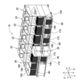
- FIG. 2 is a perspective view showing a substrate-related operating system.
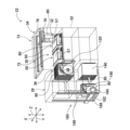
- FIG. 2 is a perspective view showing a mounting device and a feeder replacing device.
- FIG. 2 is a perspective view showing a tape feeder.
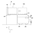
- FIG. FIG. 2 is a side view showing a feeder storage unit and an automatic transport vehicle.
- FIG. 2 is a schematic diagram showing a substrate-related operation system and a rack management device.
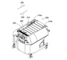
- FIG. 13 is a diagram showing a storage rack placed on an automatic guided vehicle.
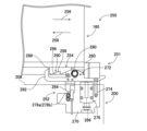
- FIG. FIG. 13A and 13B are diagrams showing a locking mechanism in which a second latched portion is not formed.
- FIG. FIG. 13 is a diagram showing a storage rack placed on an automatic guided vehicle.
- the substrate-related work system 10 is shown in FIG. 1.
- the substrate-related work system 10 shown in FIG. 1 is a system for mounting electronic components on a circuit board.
- the substrate-related work system 10 is composed of one feeder storage 20, five mounting devices 22, and one feeder exchange device 26.
- the one feeder storage 20 and the five mounting devices 22 are arranged in a row, adjacent to each other in the order of one feeder storage 20, five mounting devices 22.
- the feeder exchange device 26 is arranged in front of the feeder storage 20 and the mounting device 22 (the near side of FIG. 1).
- the direction in which the feeder storage 20 and the mounting devices 22 are lined up is referred to as the X direction
- the horizontal direction perpendicular to the X direction is referred to as the Y direction
- the direction perpendicular to the X direction and the Y direction is referred to as the Z direction.
- the side where the feeder storage 20 is located is referred to as the upstream side
- the side where the mounting device 22 is located is referred to as the downstream side.
- each of the five mounting devices 22 has substantially the same configuration, and as shown in FIG. 2, each of the five mounting devices 22 includes a conveying device 30, a mounting head 32, a mounting head moving device (hereinafter sometimes abbreviated as "moving device") 34, and a supply device 36.
- the transport device 30 is equipped with two conveyor devices 50.
- the two conveyor devices 50 are arranged on a base 52 so as to be parallel to each other and extend in the X direction.
- Each of the two conveyor devices 50 transports a circuit board 57 supported by each conveyor device 50 in the X direction by an electromagnetic motor (not shown).
- Each conveyor device 50 also has a board holding device (not shown) that holds the circuit board 57 fixedly at a predetermined position.
- the mounting head 32 mounts electronic components on the circuit board 57. More specifically, the mounting head 32 has a suction nozzle 60 provided on its bottom end surface. The suction nozzle 60 is connected to a positive and negative pressure supply device (not shown) via negative pressure air and positive pressure air passages. The suction nozzle 60 suctions and holds the electronic component by negative pressure, and releases the held electronic component by positive pressure.
- the mounting head 32 also has a nozzle lifting device (not shown) that raises and lowers the suction nozzle 60. The nozzle lifting device allows the mounting head 32 to change the vertical position of the electronic component it holds.
- the moving device 34 is a device that moves the mounting head 32 to any position on the base 52. More specifically, the moving device 34 is composed of an X-direction slide mechanism 70 and a Y-direction slide mechanism 72.
- the Y-direction slide mechanism 72 is disposed on a beam 73 suspended above the base 52, and has a Y-direction slider 76 that slides in the Y direction.
- the Y-direction slider 76 is moved to any position in the Y direction by the drive of an electromagnetic motor (not shown).
- the X-direction slide mechanism 70 has an X-direction slider 80, which is held by the Y-direction slider 76 so as to be slidable in the X direction.
- the X-direction slider 80 is moved to any position in the X direction by the drive of an electromagnetic motor (not shown).
- the mounting head 32 is attached to the X-direction slider 80. With this structure, the mounting head 32 is moved to any position on the base 52 by the moving device 34.
- the supply device 36 is disposed at the front end of the base 52 and has a number of tape feeders 90. As shown in FIG. 3, each tape feeder 90 has a reel 92, a delivery device 94, and a peeling device 96, and supplies electronic components at the end of the top surface. More specifically, a taped component 98 is wound around the reel 92, and the taped component 98 is pulled out from the reel 92 onto a tape guide 100.
- the taped component 98 is an electronic component that has been taped, and has feed holes (not shown) formed at a predetermined pitch.
- a sprocket 102 of the delivery device 94 meshes with the feed holes. The sprocket 102 is rotated by an electromagnetic motor 104. With this structure, the taped component 98 is delivered toward the supply position.
- the peeling device 96 also has a film peeling mechanism 106 and a gear mechanism 108.
- the film peeling mechanism 106 is a mechanism for peeling the top film 110 from the taped component 98, and is disposed in front of an opening 112 formed at the top end of the tape feeder 90.
- the gear mechanism 108 is a mechanism for pulling the top film 110 peeled from the taped component 98 into the film recovery section 114. With this structure, the top film 110 is peeled off from the taped component 98, and the electronic components housed in the taped component 98 are exposed at the opening 112, and the exposed electronic components are sucked and held by the suction nozzle 60 of the mounting head 32. In other words, the opening 112 is the electronic component supply position of the tape feeder 90.
- a tape guide passage 116 is formed on the side of the opening 112 in the direction in which the taped component 98 is fed out, so as to face downward. Through this tape guide passage 116, the waste tape 118 from which the electronic components have been removed from the tape component 98 is discharged.
- the tape feeder 90 is detachably attached to a tape feeder holder 120 that is fixedly attached to the front end of the base 52.
- the tape feeder holder 120 has a plurality of rails (not shown) extending in the Y direction aligned in the X direction, and the tape feeder 90 is detachably attached to each rail.
- a storage case 140 is disposed below the tape feeder holding table 120. Similar to the tape feeder holding table 120, the storage case 140 also has a plurality of rails (not shown) extending in the Y direction aligned in the X direction, and a tape feeder 90 is removably attached to each rail.
- the feeder storage 20 has a storage space 150 formed at the same height as the tape feeder holding table 120 of the mounting device 22.
- the storage space 150 is a space for storing the storage rack 160.
- the storage rack 160 is box-shaped with an opening on the front side.
- the internal height dimension of the box-shaped storage rack 160 is slightly larger than the height dimension of the tape feeder 90, and the internal depth dimension of the storage rack 160 is slightly larger than the depth dimension of the tape feeder 90.
- the internal width dimension of the storage rack 160 is N times (e.g., 30 times) larger than the width dimension of the tape feeder 90.
- N tape feeders 90 can be stored side by side inside the storage rack 160 of this shape.
- N rails 164 are formed on the lower surface of the top plate 162 of the storage rack 160 so as to extend in the front-rear direction. Therefore, by fitting the upper end of the tape feeder 90 into the rail 164 and pushing the tape feeder 90 into the interior of the storage rack 160, the tape feeder 90 is stored in a positioned state inside the storage rack 160.
- the inner dimension in the depth direction of the storage space 150 is slightly larger than the outer dimension in the depth direction of the storage rack 160, and the inner dimension in the width direction of the storage space 150, i.e., in the X direction, is slightly larger than twice the outer dimension in the width direction of the storage rack 160.
- the top of the storage space 150 is open. Therefore, as shown in FIG. 1, two storage racks 160 can be stored side by side in the X direction in the storage space 150.
- the feeder replacement device 26 replaces the tape feeders 90 for each of the feeder storage 20 and the five mounting devices 22.
- an upper guide rail 170 and a lower guide rail 172 are disposed on the front of the feeder storage 20 and the five mounting devices 22 so as to extend in the X direction.
- the feeder replacement device 26 is held by the upper guide rail 170 and the lower guide rail 172 so as to be slidable in the X direction, and is moved to any position in the X direction by the drive of an electromagnetic motor (not shown).
- the feeder exchange device 26 has a lifting device 180, a horizontal movement device 182, and a clamp mechanism 184.
- the lifting device 180 has a pair of Z-direction guide rails 186, which are disposed in front of the tape feeder holder 120 and the storage case 140 of the mounting device 22 so as to extend in the Z direction.
- the horizontal movement device 182 has an X-direction guide rail 188, which is held by the pair of Z-direction guide rails 186 so as to extend in the X direction.
- the X-direction guide rail 188 is moved to any position in the Z direction by the drive of a Z-direction motor (not shown).
- the X-direction guide rail 188 also holds a clamp mechanism 184 so as to be movable along its own axis.
- the clamp mechanism 184 is moved to any position in the X direction by the drive of an X-direction motor (not shown). Furthermore, the clamp mechanism 184 is expandable and contractable in the Y direction, and is expanded and contracted in the Y direction by driving an expansion motor (not shown).
- a clamper 190 that clamps the tape feeder 90 is provided at the tip of the clamp mechanism 184. With this structure, the feeder exchange device 26 automatically exchanges the tape feeder 90 between the tape feeder holder 120, the storage case 140, and the storage rack 160.
- the circuit board 57 is transported by the transport device 30 inside the five mounting devices 22, and the mounting device 22 mounts electronic components on the circuit board 57.
- the circuit board 57 is first transported to the mounting device located at the most upstream of the five mounting devices 22.
- the circuit board 57 is transported to the work position and fixedly held at that position.
- the tape feeder 90 mounted on the tape feeder holding table 120 feeds out the taped components 98 and supplies the electronic components at the supply position.
- the mounting head 32 moves above the supply position of the electronic components and sucks and holds the electronic components with the suction nozzle 60.
- the mounting head 32 moves above the circuit board 57 and mounts the held electronic components on the circuit board.
- the circuit board is transported downstream and loaded into the mounting device located downstream. The above mounting operations are then carried out in sequence on each mounting device to produce circuit boards with electronic components mounted.
- the mounting device 22 is configured to suck and hold the electronic components supplied by the tape feeder 90 by the suction nozzle 60 of the mounting head 32, and to mount the sucked and held electronic components on the circuit board.
- the tape feeder 90 mounted on the tape feeder holding table 120 is replaced by the feeder replacement device 26 to accommodate the supply of electronic components, change of setup, etc. That is, the tape feeder 90 to be replaced is removed from the tape feeder holding table 120 by the clamp mechanism 184 of the feeder replacement device 26. The removed tape feeder 90 is then stored in an empty slot of the storage case 140 or the storage rack 160.
- the tape feeder to be mounted on the tape feeder holding table 120 is clamped from the storage case 140 or the storage rack 160 by the clamp mechanism 184 of the feeder replacement device 26 by the clamp mechanism 184 of the feeder replacement device 26.
- the tape feeder 90 clamped by the clamp mechanism 184 is then mounted on the tape feeder holding table 120.
- the storage case 140 basically contains tape feeders 90 that contain electronic components necessary for the mounting operation being performed by the mounting device 22. Therefore, when replenishing electronic components during the mounting operation, the tape feeders 90 are exchanged between the tape feeder holder 120 and the storage case 140.
- the storage rack 160 of the feeder storage 20 basically contains tape feeders 90 that contain electronic components necessary for the next mounting operation (hereinafter referred to as the "next mounting operation") following the mounting operation being performed by the mounting device 22. Therefore, when preparing for the next mounting operation, the tape feeders 90 are exchanged between the tape feeder holder 120 of the mounting device 22 and the storage rack 160 of the feeder storage 20, or between the storage case 140 of the mounting device 22 and the storage rack 160 of the feeder storage 20.
- the storage rack 160 is automatically replaced by the automatic transport vehicle 200 shown in FIG. 5.
- the automatic transport vehicle 200 is provided with a pair of drive wheels (only one of the pair of drive wheels is shown in the figure) 204 and a pair of steering wheels (only one of the pair of steering wheels is shown in the figure) 206 arranged on the underside of the housing 202.
- the operation of the drive wheels 204 and the steering wheels 206 is controlled by a control device 207.
- the automatic transport vehicle 200 can be automatically moved to any position on the floor 209 on which the substrate-related work system 10 is arranged by the control of the control device 207.
- a top plate 208 is arranged on the top surface of the housing 202, and a plurality of transport rollers 210 are arranged in a row in the front-rear direction on the top surface of the top plate 208 in a posture extending in the left-right direction.
- each of the plurality of transport rollers 210 is capable of rotating about an axis extending in the left-right direction.
- the multiple transport rollers 210 rotate in any direction by being driven by an electromagnetic motor (not shown).
- a number of transport rollers 220 are arranged side by side in the Y direction in an orientation extending in the X direction.
- Each of the multiple transport rollers 220 is rotatable about an axis extending in the X direction.
- the multiple transport rollers 220 are rotated in any direction by the drive of an electromagnetic motor (not shown).
- the upper end positions of the transport rollers 220 of the feeder storage 20 and the upper end positions of the transport rollers 210 of the automatic transport cart 200 are at approximately the same height.
- the storage rack 160 stored in the storage space 150 is automatically transferred to the automatic transport vehicle 200.
- the automatic transport vehicle 200 moves to a position facing the storage space 150 in which the storage rack (hereinafter referred to as "unnecessary rack 160a") is stored by the operation of the drive wheels 204 and steering wheels 206.
- the multiple transport rollers 220 of the feeder storage 20 rotate in the direction to transport the unnecessary rack 160a out
- the multiple transport rollers 210 of the automatic transport vehicle 200 rotate in the direction to transport the unnecessary rack 160a in.
- the unnecessary rack 160a stored in the storage space 150 is automatically transferred to the automatic transport vehicle 200.
- a rack management device 230 is also installed on the floor 209 on which the substrate-related work system 10 is installed.
- the rack management device 230 is a device that manages the storage racks 160, and like the feeder storage 20, has a storage space 232, in which two storage racks 160 can be stored side by side.
- the rack management device 230 shown in FIG. 6 stores one storage rack (hereinafter, referred to as "necessary rack 160b").
- the necessary rack 160b stores a tape feeder 90 that supplies electronic components scheduled to be mounted in the next mounting operation in the mounting device 22. Note that the space next to the necessary rack 160b is left empty.
- a plurality of transport rollers 234 are arranged on the underside of the storage space 232 of the rack management device 230, and the plurality of transport rollers 234 are also rotated in any direction by the drive of an electromagnetic motor (not shown).
- the automatic transport vehicle 200 moves to a position facing the empty space of the rack management device 230. Then, the multiple transport rollers 210 of the automatic transport vehicle 200 rotate in the direction to transport the unnecessary rack 160a out, and the multiple transport rollers 234 of the rack management device 230 rotate in the direction to transport the unnecessary rack 160a in. As a result, the unnecessary rack 160a placed on the automatic transport vehicle 200 is automatically transferred to the storage space 232 of the rack management device 230. Next, the automatic transport vehicle 200 moves to a position facing the necessary rack 160b stored in the storage space 232 of the rack management device 230.
- the multiple transport rollers 234 of the rack management device 230 rotate in a direction to transport the necessary rack 160b out, and the multiple transport rollers 210 of the automated guided vehicle 200 rotate in a direction to transport the necessary rack 160b in.
- the necessary rack 160b stored in the rack management device 230 is automatically transferred to the automated guided vehicle 200.
- the automated transport vehicle 200 onto which the necessary rack 160b has been transferred moves to a position facing the empty space in the feeder storage 20, that is, the space where the unnecessary rack 160a was placed. Then, the multiple transport rollers 210 of the automated transport vehicle 200 rotate in the direction to transport the necessary rack 160b out, and the multiple transport rollers 220 of the feeder storage 20 rotate in the direction to transport the necessary rack 160b in. As a result, the necessary rack 160b placed on the automated transport vehicle 200 is automatically transferred to the storage space 150 of the feeder storage 20.
- the unnecessary rack 160a stored in the feeder storage 20 is automatically replaced with the necessary rack 160b by the automatic transport vehicle 200.
- the automatic transport vehicle 200 moves between the feeder storage 20 and the rack management device 230, there is a risk that the storage rack 160 placed on the upper surface of the automatic transport vehicle 200 will fall from the automatic transport vehicle 200.
- a plurality of transport rollers 210 are arranged on the upper surface of the automatic transport vehicle 200, and the storage rack 160 placed on the plurality of transport rollers 210 slides in a predetermined direction, that is, in the direction in which the plurality of transport rollers 210 are arranged.
- the storage rack 160 is arranged on the upper surface of the automatic transport vehicle 200 so as to be slidable in the direction in which the plurality of transport rollers 210 are arranged. For this reason, there is a risk that the storage rack 160 placed on the upper surface of the automatic transport vehicle 200 will fall from the automatic transport vehicle 200 when the automatic transport vehicle 200 moves.
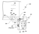
- a locking mechanism 251 is provided in the automated guided vehicle 200 and the storage rack 160, i.e., the transport device 250 composed of the automated guided vehicle 200 and the storage rack 160.
- the lock mechanism 251 is composed of a latch mechanism 252 arranged on the top plate 208 of the automatic transport vehicle 200 and a latched block 254 arranged on the underside of the storage rack 160.
- the storage rack 160 placed on the upper surface of the automatic transport vehicle 200 slides in the direction of arrow 256 when it is carried into the upper surface of the automatic transport vehicle 200, and slides in the direction of arrow 258 when it is carried out from the upper surface of the automatic transport vehicle 200.
- the sliding of the storage rack 160 in the direction of carrying into the automatic transport vehicle 200 (hereinafter referred to as the "rack carrying-in direction") (arrow 256) is restricted by a stopper 260 fixed to the upper surface of the automatic transport vehicle 200.
- the position where the sliding is restricted by the stopper 260 is the fixed position when the storage rack 160 is transported (hereinafter referred to as the "transport position").
- the locking mechanism 251 restricts the sliding of the storage rack 160, which is located in the transport position, in the direction of removal from the automated guided vehicle 200 (hereinafter referred to as the "rack removal direction") (arrow 258).
- the rack removal direction (arrow 256) and the rack removal direction (arrow 258) may be referred to as the sliding direction of the storage rack 160.
- the hook mechanism 252 has a base 270, a hook lever 272, a coil spring 274, a solenoid 276, and a first detection sensor 278.
- the base 270 is fixed to the top plate 208 of the automatic guided cart 200, and the hook lever 272 is disposed on the upper end of the base 270 in a position extending in the sliding direction of the storage rack 160.
- the hook lever 272 is supported by a support shaft 280 so as to be swingable at the center in the sliding direction of the storage rack 160.
- the hook lever 272 has a hook shape at the end (hereinafter referred to as the "tip") on the side of the rack ejection direction (arrow 258), and the tip is a hook portion 282 that is bent upward.
- the coil spring 274 is connected to the end (hereinafter referred to as the "rear end") opposite the tip of the hook lever 272.
- the coil spring 274 is disposed so as to extend in the vertical direction, and the other end of the coil spring 274 is connected to the base 270 below the latch lever 272.
- the coil spring 274 is a tension spring, and the rear end of the latch lever 272 is biased downward by the elastic force of the coil spring 274. Therefore, the tip of the latch lever 272, i.e., the latch portion 282, is biased upward by the elastic force of the coil spring 274.
- a protrusion 284 extending downward is disposed on the underside of the latch lever 272 on the side of the support shaft 280 between the support shaft 280 and the latch portion 282.
- the solenoid 276 is disposed below the latch lever 272, between the support shaft 280 and the rear end of the latch lever 272, in a position extending in the vertical direction.
- the plunger 286 extends upward from the upper surface of the solenoid 276. This causes the upper end of the plunger 286 to come into contact between the rear end of the latch lever 272 and the support shaft 280, causing the rear end of the latch lever 272 to swing upward against the elastic force of the coil spring 274.
- the tip of the latch lever 272, i.e., the latch portion 282 swings downward against the elastic force of the coil spring 274.
- the plunger 286 does not extend from the upper surface of the solenoid 276, and is located inside the solenoid 276.
- the upper end of the plunger 286 does not contact the latch lever 272, and the rear end of the latch lever 272 swings downward due to the elastic force of the coil spring 274.
- the tip of the latch lever 272, i.e., the latch portion 282 swings upward due to the elastic force of the coil spring 274.
- the first detection sensor 278 is a photoelectric sensor and is composed of a light-emitter 278a and a light-receiver 278b.
- the light-emitter 278a and the light-receiver 278b are arranged to sandwich the protrusion 284 of the hook lever 272, and the light emitted from the light-emitter 278a is received by the light-receiver 278b.
- the hook lever 272 swings, the light emitted from the light-emitter 278a is blocked by the protrusion 284 and is not received by the light-receiver 278b. In other words, as shown in FIG.
- the hooked block 254 is fixed to the underside of the storage rack 160, and faces the space between the hook portion 282 of the hook lever 272 and the support shaft 280 when the storage rack 160 is placed in the transport position, as shown in FIG. 8. Therefore, when the storage rack 160 is placed in the transport position, the hooked block 254 is hooked by the hook portion 282 of the hook lever 272 at the end face 288 on the side of the rack ejection direction (arrow 258) of the hooked block 254. In other words, the end face 288 of the hooked block 254 functions as a first hooked portion that is hooked to the hook portion 282 of the hook lever 272 when the storage rack 160 is placed in the transport position.
- a recess 290 is formed on the bottom surface of the hook block 254 at a position slightly shifted from the end surface 288 in the rack loading direction (arrow 256).
- the inner wall surface on the side of the rack unloading direction (arrow 258) is a tapered surface 296, and the inner wall surface on the side of the rack loading direction (arrow 256) is a vertical surface 298. Therefore, when the storage rack 160 shifts from the transport position in the rack unloading direction (arrow 258), as shown in FIG. 9, the hook block 254 is hooked by the hook portion 282 of the hook lever 272 in the recess 290.
- the recess 290 of the hook block 254 functions as a second hook portion that is hooked to the hook portion 282 of the hook lever 272 when the storage rack 160 shifts from the transport position in the rack unloading direction (arrow 258).
- the end face 288 of the hooked block 254, which functions as the first hooked portion, and the recess 290 of the hooked block 254, which functions as the second hooked portion, are formed side by side in the sliding direction of the storage rack. Then, the hooking portion 282 of the hooking lever 272 hooks onto the end face 288 of the hooked block 254, locking the storage rack 160 in the transport position, and when the storage rack 160 shifts from the transport position in the rack removal direction (arrow 258), the hooking portion 282 of the hooking lever 272 hooks onto the recess 290 of the hooked block 254.
- the hook portion 282 of the hook lever 272 is hooked to the end face 288 of the hooked block 254, that is, when the storage rack 160 is placed in the transport position, as shown in FIG. 8, the protrusion 284 of the hook lever 272 is not located between the light projector 278a and the light receiver 278b of the first detection sensor 278. Therefore, the light projected from the light projector 278a is received by the light receiver 278b.
- the hook portion 282 of the hook lever 272 is hooked to the recess 290 of the hooked block 254, that is, when the storage rack 160 is displaced from the transport position, as shown in FIG.
- the protrusion 284 of the hook lever 272 enters between the light projector 278a and the light receiver 278b of the first detection sensor 278. Therefore, the light emitted from the light-emitter 278a is blocked by the protrusion 284 and is not received by the light-receiver 278b. This allows the first detection sensor 278 to detect whether the hook portion 282 of the hook lever 272 is hooked to the end face 288 or the recess 290 of the hooked block 254, that is, whether the hook portion 282 of the hook lever 272 is hooked to the end face 288 of the hooked block 254.
- the first detection sensor 278 can detect whether the storage rack 160 has shifted from its transport position, that is, detect the shift of the storage rack 160 from its transport position.
- the transport device 250 when the storage rack 160 is placed in the transport position, the storage rack 160 is locked by the locking mechanism 251, and if the storage rack 160 deviates from the transport position, the movement of the automatic transport cart 200 is stopped. Specifically, when the storage rack 160 is placed in the transport position, the hook portion 282 of the hook lever 272 is urged upward by the elastic force of the coil spring 274 and hooked onto the end face 288 of the hooked block 254, thereby locking the storage rack 160.
- the first detection sensor 278 detects that the light receiver 278b is receiving light.
- the first detection sensor 278 is connected to the control device 207, and when it detects that the light receiver 278b is receiving light, the first detection sensor 278 outputs an ON signal to the control device 207.
- vibrations during movement of the automated guided vehicle 200 may cause the hooking portion 282 of the hooking lever 272 to come off the end surface 288 of the hooked block 254.
- the storage rack 160 shifts from its transport position, and the hooking portion 282 of the hooking lever 272 hooks into the recess 290 of the hooked block 254.
- the first detection sensor 278 detects that the light receiver 278b is not receiving light, and outputs an OFF signal to the control device 207.
- the control device 207 determines whether the OFF signal is continuously input for a set time (e.g., 0.1 seconds).
- the control device 207 outputs a stop command to the drive wheels 204 and the steered wheels 206 as error information. Then, the drive wheels 204 and steering wheels 206 stop the movement of the automated guided vehicle 200 in accordance with the stop command. This makes it possible to prevent the storage rack 160 from falling off the automated guided vehicle 200 if the storage rack 160 shifts from its transport position.
- the control device 207 does not output a stop command to the drive wheels 204 and the steered wheels 206. This is because the hook portion 282 of the hook lever 272 swings downward due to vibrations during the movement of the automatic guided vehicle 200, but may not come off the end face 288 of the hooked block 254. Also, the hook portion 282 of the hook lever 272 swings downward and once comes off the end face 288 of the hooked block 254, but may hook on the end face 288 again.
- the movement of the automatic guided vehicle 200 may stop even if the hook portion 282 of the hook lever 272 does not come off the end face 288 of the hooked block 254. This makes it possible to stop the movement of the automated guided vehicle 200 only when the hook portion 282 comes off the end surface 288 and the storage rack 160 shifts from the transport position.
- the control device 207 outputs a generation command as error information not only to the drive wheels 204 and steering wheels 206 but also to a speaker (not shown) built into the automated guided vehicle 200. The speaker then generates a buzzer sound or the like in accordance with the generation command. This allows the operator to recognize an abnormality in the automated guided vehicle 200.
- the first detection sensor 278 outputs an OFF signal, thereby stopping the movement of the automatic guided vehicle 200.
- the hook portion 282 of the hook lever 272 that has come off the end face 302 of the hooked block 300 only comes into contact with the lower surface of the hooked block 300 and does not hook at any point on the hooked block 300.
- a recess 290 is formed aligned with the end face 288 of the latched block 254 in the sliding direction of the storage rack 160.
- the latch part 282 of the latch lever 272 that has come off the end face 288 of the latched block 254 is latched into the recess 290, so that the storage rack 160 can be locked again by the lock mechanism 251, and therefore the storage rack 160 can be reliably prevented from falling off the automated guided vehicle 200.
- the hook portion 282 of the hook lever 272 hooks onto the vertical surface 298 of the recess 290, which effectively prevents the storage rack 160 from sliding in the rack removal direction (arrow 258).
- the transport device 250 is also provided with a second detection sensor (see FIG. 11) 310 different from the first detection sensor 278 as a sensor for detecting deviation of the storage rack 160 from the transport position, and the movement of the automatic transport cart 200 is stopped according to the detection value of the second detection sensor 310.
- the second detection sensor 310 is also a photoelectric sensor, and as shown in FIG. 11, is composed of a light projector 310a and a light receiver 310b.
- the light projector 310a and the light receiver 310b are arranged to sandwich the upper part of the transport roller 210 at the end opposite to the end on the side where the hook mechanism 252 of the top plate 208 of the automatic transport cart 200 is arranged, that is, the end on the side of the rack discharge direction (arrow 258).
- the light projected from the light projector 310a is received by the light receiver 310b. Therefore, when the storage rack 160 is being transported in and out by the transport rollers 210, the light projected from the light projector 278a is blocked by the storage rack 160 and is not received by the light receiver 278b.
- the second detection sensor 310 can detect the relative position of the storage rack 160 with respect to the automated guided vehicle 200, thereby determining whether the storage rack 160 has shifted from its position at the time of transport, i.e., detecting the shift of the storage rack 160 from its position at the time of transport.
- the movement of the automated transport vehicle 200 is stopped according to the detection value of not only the first detection sensor 278 but also the second detection sensor 310.
- the hook portion 282 of the hook lever 272 hooks onto the end face 288 of the hooked block 254, thereby locking the storage rack 160.
- the second detection sensor 310 detects that the light receiver 278b is receiving light, and outputs an ON signal to the control device 207.
- the storage rack 160 shifts from its transport position and the hook portion 282 of the hook lever 272 hooks into the recess 290 of the hooked block 254.
- the second detection sensor 310 detects that the light receiver 278b is not receiving light, and outputs an OFF signal to the control device 207.
- the control device 207 outputs a stop command to the drive wheels 204 and steered wheels 206 as error information.
- the control device 207 when an OFF signal is input from the first detection sensor 278, the control device 207 outputs error information on the condition that the input of the OFF signal continues for a set time, but when an OFF signal is input from the second detection sensor 310, the control device 207 outputs error information without the condition that the input of the OFF signal continues for a set time.
- the second detection sensor 310 detects the relative position of the storage rack 160 with respect to the automatic guided vehicle 200, and when the second detection sensor 310 detects a positional deviation, the hook portion 282 of the hook lever 272 is disengaged from the end face 288 of the hooked block 254. Then, the drive wheels 204 and the steering wheels 206 stop the movement of the automatic guided vehicle 200 in accordance with the stop command.
- the control device 207 outputs a generation command as error information not only to the drive wheels 204 and the steering wheels 206 but also to a speaker built into the automated guided vehicle 200, and the speaker generates a buzzer sound or the like in accordance with the generation command.
- the transport device 250 is provided with two sensors, the first detection sensor 278 and the second detection sensor 310, and when at least one of the two sensors detects a deviation of the storage rack 160 from its transport position, the automated guided vehicle 200 stops and a buzzer sound is generated. This makes it possible to reliably detect a deviation of the storage rack 160 from its transport position, stop the automated guided vehicle 200, and generate a buzzer sound.
- the storage rack 160 is an example of a transported object.
- the automated transport vehicle 200 is an example of a vehicle.
- the control device 207 is an example of an output device.
- the transport device 250 is an example of a transport device.
- the first detection sensor 278 is an example of a sensor.
- the hook portion 282 is an example of a hook portion.
- the end surface 288 is an example of a first hooked portion.
- the recess 290 is an example of a hooked portion other than the first hooked portion.
- the second detection sensor 310 is an example of a sensor.
- this embodiment provides the following advantages:
- the hooked block 254 has an end face 288 and a recess 290 formed side by side in the sliding direction of the storage rack 160.
- the storage rack 160 is placed in the transport position of the automatic transport cart 200 by hooking the hook portion 282 of the hook lever 272 to the end face 288 of the hooked block 254, and if the storage rack 160 shifts from the transport position, the hook portion 282 of the hook lever 272 hooks to the recess 290 of the hooked block 254. This makes it possible to prevent the storage rack 160 from falling off the automatic transport cart 200.
- the automated transport vehicle 200 is also provided with a first detection sensor 278 and a second detection sensor 310 that detect deviation of the storage rack 160 from its transport position. If at least one of the first detection sensor 278 and the second detection sensor 310 detects deviation of the storage rack 160 from its transport position, the control device 207 outputs error information. This allows measures to be taken to prevent the storage rack 160 from falling.
- the first detection sensor 278 detects whether the hook portion 282 of the hook lever 272 is hooked to the end face 288 of the hooked block 254, thereby detecting any deviation of the storage rack 160 from the transport position. This makes it possible to properly detect any deviation of the storage rack 160 from the transport position.
- the second detection sensor 310 also detects the relative position of the storage rack 160 with respect to the automated guided vehicle 200, thereby detecting any deviation of the storage rack 160 from its position at the time of transport. This makes it possible to properly detect any deviation of the storage rack 160 from its position at the time of transport.
- the control device 207 outputs error information. As a result, error information is output only when the storage rack 160 has been displaced from its transport position.
- the present disclosure is not limited to the above embodiment, but can be embodied in various forms with various modifications and improvements based on the knowledge of those skilled in the art.
- the end face 288 and the recess 290 are formed on the hook block 254 in two hook portions aligned in the sliding direction of the storage rack 160, but three or more hook portions may be formed aligned in the sliding direction of the storage rack 160.
- the hook portion 282 of the hook lever 272 is hook-shaped, but various shapes such as convex portions, projections, recesses, hook shapes, etc. can be used as long as the shape allows hooking to the hooked portion.
- the hooked portion is not limited to the end surface 288 and recesses 290 of the hooked block 254, and various shapes such as convex portions, projections, recesses, hook shapes, etc. can be used as long as the shape allows hooking to the hooked portion.
- two sensors are provided on the automatic transport vehicle 200, but one of the two sensors may be provided on the automatic transport vehicle 200.
- the sensor is capable of detecting the deviation of the storage rack 160 from the position during transport, it is possible to employ a sensor that can detect the positional deviation of the storage rack by various methods.
- the control device 207 when an OFF signal is input from the second detection sensor 310, the control device 207 outputs error information without the condition that the input of the OFF signal continues for a set time.
- the control device 207 may output error information on the condition that the input of the OFF signal continues for a set time, as in the case where an OFF signal is input from the second detection sensor 310.
- the movement direction of the automatic transport vehicle 200 and the direction in which the multiple transport rollers 210 are lined up are the same.
- the movement direction of the automatic transport vehicle 200 and the sliding direction of the storage rack 160 are the same, and the direction in which the multiple hooked parts are lined up is the same as the movement direction of the automatic transport vehicle 200.
- the movement direction of the automatic transport vehicle 200 and the sliding direction of the storage rack 160 may be different, and the direction in which the multiple hooked parts are lined up may be different from the movement direction of the automatic transport vehicle 200.
- the storage rack 160 that stores the tape feeders 90 is transported by the automatic transport vehicle 200, but this is not limited to the storage rack 160, and various other objects may be transported by the automatic transport vehicle 200.
- a tray magazine that stores trays for placing components a mask magazine that stores masks used for solder printing, a board magazine that stores boards, etc. may be transported by the automatic transport vehicle 200.
- this is not limited to tools used in mounting work, and various other transported objects may be transported by the automatic transport vehicle 200.
- the present invention is applied to the automated guided vehicle 200 that moves automatically, but the present invention may also be applied to a vehicle that is moved manually by an operator.
- Storage rack (transported object) 200: Automatic transport cart (cart) 207: Control device (output device) 250: Transport device 278: First detection sensor (sensor) 282: Hanging part 288: End face (first hooked part) 290: Recess (hooked part other than the first hooked part) 310: Second detection sensor
Landscapes
- Engineering & Computer Science (AREA)
- Manufacturing & Machinery (AREA)
- Microelectronics & Electronic Packaging (AREA)
- Warehouses Or Storage Devices (AREA)
Abstract
Description
Claims (7)
- 掛止部を有する台車と、
所定の方向にスライド可能に前記台車に載置され、前記台車の移動により搬送される被搬送体と、
を備え、
前記掛止部が掛止する複数の被掛止部が前記被搬送体に前記所定の方向に並んで形成されており、
前記掛止部が前記複数の被掛止部のうちの第1の被掛止部に掛止することで前記被搬送体が前記台車における所定の位置に載置され、前記被搬送体が前記所定の位置からズレた場合に前記掛止部が前記複数の被掛止部のうちの前記第1の被掛止部以外の被掛止部に掛止する搬送装置。 - 前記台車は、
前記所定の位置からの前記被搬送体のズレを検出するセンサと、
前記所定の位置からの前記被搬送体のズレが前記センサにより検出された場合にエラー情報を出力する出力装置と、
を備える請求項1に記載の搬送装置。 - 前記センサは、
前記被搬送体の前記台車に対する相対的な位置を検出することで、前記所定の位置からの前記被搬送体のズレを検出する請求項2に記載の搬送装置。 - 前記センサは、
前記掛止部が前記第1の被掛止部に掛止しているか否かを検出することで、前記所定の位置からの前記被搬送体のズレを検出する請求項2に記載の搬送装置。 - 前記台車は、自動で移動するものであり、
前記出力装置によりエラー情報が出力された場合に前記台車の移動が自動停止する請求項2に記載の搬送装置。 - 前記出力装置は、
前記所定の位置からの前記被搬送体のズレが前記センサにより設定時間、継続して検出された場合にエラー情報を出力する請求項2ないし請求項5のいずれか1項に記載の搬送装置。 - 所定の方向にスライド可能に台車に載置され、前記台車の移動により搬送される被搬送体であって、
前記台車に配設された掛止部に掛止される複数の被掛止部が前記被搬送体に前記所定の方向に並んで形成されており、
前記掛止部が前記複数の被掛止部のうちの第1の被掛止部に掛止することで前記被搬送体が前記台車における所定の位置に載置され、前記被搬送体が前記所定の位置からズレた場合に前記掛止部が前記複数の被掛止部のうちの前記第1の被掛止部以外の被掛止部に掛止する被搬送体。
Priority Applications (4)
| Application Number | Priority Date | Filing Date | Title |
|---|---|---|---|
| CN202380092830.9A CN120570080A (zh) | 2023-02-10 | 2023-02-10 | 搬运装置及被搬运体 |
| PCT/JP2023/004564 WO2024166362A1 (ja) | 2023-02-10 | 2023-02-10 | 搬送装置、および被搬送体 |
| DE112023005769.9T DE112023005769T5 (de) | 2023-02-10 | 2023-02-10 | Fördervorrichtung und Förderkörper |
| JP2024576048A JPWO2024166362A1 (ja) | 2023-02-10 | 2023-02-10 |
Applications Claiming Priority (1)
| Application Number | Priority Date | Filing Date | Title |
|---|---|---|---|
| PCT/JP2023/004564 WO2024166362A1 (ja) | 2023-02-10 | 2023-02-10 | 搬送装置、および被搬送体 |
Publications (1)
| Publication Number | Publication Date |
|---|---|
| WO2024166362A1 true WO2024166362A1 (ja) | 2024-08-15 |
Family
ID=92262253
Family Applications (1)
| Application Number | Title | Priority Date | Filing Date |
|---|---|---|---|
| PCT/JP2023/004564 Ceased WO2024166362A1 (ja) | 2023-02-10 | 2023-02-10 | 搬送装置、および被搬送体 |
Country Status (4)
| Country | Link |
|---|---|
| JP (1) | JPWO2024166362A1 (ja) |
| CN (1) | CN120570080A (ja) |
| DE (1) | DE112023005769T5 (ja) |
| WO (1) | WO2024166362A1 (ja) |
Citations (4)
| Publication number | Priority date | Publication date | Assignee | Title |
|---|---|---|---|---|
| JPS5548535B2 (ja) * | 1977-06-14 | 1980-12-06 | ||
| JPS60202022A (ja) * | 1984-03-23 | 1985-10-12 | Toshiba Corp | 搬送車用移載装置 |
| JPS60232314A (ja) * | 1984-05-02 | 1985-11-19 | Nissan Motor Co Ltd | 移載装置の荷物保持フツク作動機構 |
| JPH0254156B2 (ja) * | 1984-11-01 | 1990-11-20 | Daifuku Kk |
-
2023
- 2023-02-10 JP JP2024576048A patent/JPWO2024166362A1/ja active Pending
- 2023-02-10 CN CN202380092830.9A patent/CN120570080A/zh active Pending
- 2023-02-10 DE DE112023005769.9T patent/DE112023005769T5/de active Pending
- 2023-02-10 WO PCT/JP2023/004564 patent/WO2024166362A1/ja not_active Ceased
Patent Citations (4)
| Publication number | Priority date | Publication date | Assignee | Title |
|---|---|---|---|---|
| JPS5548535B2 (ja) * | 1977-06-14 | 1980-12-06 | ||
| JPS60202022A (ja) * | 1984-03-23 | 1985-10-12 | Toshiba Corp | 搬送車用移載装置 |
| JPS60232314A (ja) * | 1984-05-02 | 1985-11-19 | Nissan Motor Co Ltd | 移載装置の荷物保持フツク作動機構 |
| JPH0254156B2 (ja) * | 1984-11-01 | 1990-11-20 | Daifuku Kk |
Also Published As
| Publication number | Publication date |
|---|---|
| CN120570080A (zh) | 2025-08-29 |
| DE112023005769T5 (de) | 2025-11-20 |
| JPWO2024166362A1 (ja) | 2024-08-15 |
Similar Documents
| Publication | Publication Date | Title |
|---|---|---|
| CN101330821B (zh) | 部件安装装置及部件安装装置的部件供给方法 | |
| JP5980594B2 (ja) | リールストッカ及び電子部品供給台車 | |
| CN112154069A (zh) | 收纳装置及印刷系统 | |
| WO2001026440A1 (en) | Device for transferring/holding sheetlike member and its method | |
| JP7783345B2 (ja) | トレイ式部品供給装置 | |
| WO2018087857A1 (ja) | 部品供給装置、表面実装機、及び部品供給方法 | |
| CN120019005A (zh) | 无人搬运车 | |
| JP2022029710A (ja) | 部品搭載装置 | |
| JP7116195B2 (ja) | 搬送装置 | |
| JP2001326495A (ja) | 電子部品供給装置 | |
| CN120570080A (zh) | 搬运装置及被搬运体 | |
| CN116491238B (zh) | 元件安装系统、元件补给方法及补给元件搬运装置 | |
| JP2021015863A (ja) | 部品実装システム、部品実装システムの制御方法 | |
| CN100546454C (zh) | 电子电路部件供给装置和电子电路部件安装机 | |
| JP4322863B2 (ja) | 部品供給装置 | |
| JP7008835B2 (ja) | 部品供給装置 | |
| WO2024089757A1 (ja) | 取付デバイス | |
| WO2022157831A1 (ja) | 装着作業システム、およびテープフィーダの交換方法 | |
| JP7470917B2 (ja) | 部品供給装置 | |
| JP4667113B2 (ja) | 電子部品装着装置 | |
| JP2021180237A (ja) | 部品実装機 | |
| JP7358294B2 (ja) | 部品実装機および部品収容状態判断方法 | |
| WO2025088664A1 (ja) | 搬送装置 | |
| JP7386392B2 (ja) | 部品装着装置 | |
| WO2023166733A1 (ja) | 部品実装機及びメンテナンス方法 |
Legal Events
| Date | Code | Title | Description |
|---|---|---|---|
| 121 | Ep: the epo has been informed by wipo that ep was designated in this application |
Ref document number: 23921191 Country of ref document: EP Kind code of ref document: A1 |
|
| WWE | Wipo information: entry into national phase |
Ref document number: 2024576048 Country of ref document: JP |
|
| WWE | Wipo information: entry into national phase |
Ref document number: 202380092830.9 Country of ref document: CN |
|
| WWP | Wipo information: published in national office |
Ref document number: 202380092830.9 Country of ref document: CN |
|
| WWE | Wipo information: entry into national phase |
Ref document number: 112023005769 Country of ref document: DE |
|
| 122 | Ep: pct application non-entry in european phase |
Ref document number: 23921191 Country of ref document: EP Kind code of ref document: A1 |