WO2024166344A1 - クリーンルーム施設 - Google Patents
クリーンルーム施設 Download PDFInfo
- Publication number
- WO2024166344A1 WO2024166344A1 PCT/JP2023/004512 JP2023004512W WO2024166344A1 WO 2024166344 A1 WO2024166344 A1 WO 2024166344A1 JP 2023004512 W JP2023004512 W JP 2023004512W WO 2024166344 A1 WO2024166344 A1 WO 2024166344A1
- Authority
- WO
- WIPO (PCT)
- Prior art keywords
- room
- air
- clean
- chamber
- duct
- Prior art date
- Legal status (The legal status is an assumption and is not a legal conclusion. Google has not performed a legal analysis and makes no representation as to the accuracy of the status listed.)
- Ceased
Links
Images


Classifications
-
- A—HUMAN NECESSITIES
- A61—MEDICAL OR VETERINARY SCIENCE; HYGIENE
- A61L—METHODS OR APPARATUS FOR STERILISING MATERIALS OR OBJECTS IN GENERAL; DISINFECTION, STERILISATION OR DEODORISATION OF AIR; CHEMICAL ASPECTS OF BANDAGES, DRESSINGS, ABSORBENT PADS OR SURGICAL ARTICLES; MATERIALS FOR BANDAGES, DRESSINGS, ABSORBENT PADS OR SURGICAL ARTICLES
- A61L2/00—Disinfection or sterilisation of materials or objects, in general; Accessories therefor
- A61L2/16—Disinfection or sterilisation of materials or objects, in general; Accessories therefor using chemical substances
- A61L2/20—Gaseous substances, e.g. vapours
- A61L2/208—Hydrogen peroxide
-
- F—MECHANICAL ENGINEERING; LIGHTING; HEATING; WEAPONS; BLASTING
- F24—HEATING; RANGES; VENTILATING
- F24F—AIR-CONDITIONING; AIR-HUMIDIFICATION; VENTILATION; USE OF AIR CURRENTS FOR SCREENING
- F24F3/00—Air-conditioning systems in which conditioned primary air is supplied from one or more central stations to distributing units in the rooms or spaces where it may receive secondary treatment; Apparatus specially designed for such systems
- F24F3/12—Air-conditioning systems in which conditioned primary air is supplied from one or more central stations to distributing units in the rooms or spaces where it may receive secondary treatment; Apparatus specially designed for such systems characterised by the treatment of the air otherwise than by heating and cooling
- F24F3/16—Air-conditioning systems in which conditioned primary air is supplied from one or more central stations to distributing units in the rooms or spaces where it may receive secondary treatment; Apparatus specially designed for such systems characterised by the treatment of the air otherwise than by heating and cooling by purification, e.g. by filtering; by sterilisation; by ozonisation
- F24F3/167—Clean rooms, i.e. enclosed spaces in which a uniform flow of filtered air is distributed
-
- F—MECHANICAL ENGINEERING; LIGHTING; HEATING; WEAPONS; BLASTING
- F24—HEATING; RANGES; VENTILATING
- F24F—AIR-CONDITIONING; AIR-HUMIDIFICATION; VENTILATION; USE OF AIR CURRENTS FOR SCREENING
- F24F7/00—Ventilation
- F24F7/04—Ventilation with ducting systems, e.g. by double walls; with natural circulation
- F24F7/06—Ventilation with ducting systems, e.g. by double walls; with natural circulation with forced air circulation, e.g. by fan positioning of a ventilator in or against a conduit
-
- A—HUMAN NECESSITIES
- A61—MEDICAL OR VETERINARY SCIENCE; HYGIENE
- A61L—METHODS OR APPARATUS FOR STERILISING MATERIALS OR OBJECTS IN GENERAL; DISINFECTION, STERILISATION OR DEODORISATION OF AIR; CHEMICAL ASPECTS OF BANDAGES, DRESSINGS, ABSORBENT PADS OR SURGICAL ARTICLES; MATERIALS FOR BANDAGES, DRESSINGS, ABSORBENT PADS OR SURGICAL ARTICLES
- A61L2103/00—Materials or objects being the target of disinfection or sterilisation
- A61L2103/75—Room floors or walls
-
- A—HUMAN NECESSITIES
- A61—MEDICAL OR VETERINARY SCIENCE; HYGIENE
- A61L—METHODS OR APPARATUS FOR STERILISING MATERIALS OR OBJECTS IN GENERAL; DISINFECTION, STERILISATION OR DEODORISATION OF AIR; CHEMICAL ASPECTS OF BANDAGES, DRESSINGS, ABSORBENT PADS OR SURGICAL ARTICLES; MATERIALS FOR BANDAGES, DRESSINGS, ABSORBENT PADS OR SURGICAL ARTICLES
- A61L2202/00—Aspects relating to methods or apparatus for disinfecting or sterilising materials or objects
- A61L2202/10—Apparatus features
- A61L2202/11—Apparatus for generating biocidal substances, e.g. vaporisers, UV lamps
-
- A—HUMAN NECESSITIES
- A61—MEDICAL OR VETERINARY SCIENCE; HYGIENE
- A61L—METHODS OR APPARATUS FOR STERILISING MATERIALS OR OBJECTS IN GENERAL; DISINFECTION, STERILISATION OR DEODORISATION OF AIR; CHEMICAL ASPECTS OF BANDAGES, DRESSINGS, ABSORBENT PADS OR SURGICAL ARTICLES; MATERIALS FOR BANDAGES, DRESSINGS, ABSORBENT PADS OR SURGICAL ARTICLES
- A61L2202/00—Aspects relating to methods or apparatus for disinfecting or sterilising materials or objects
- A61L2202/10—Apparatus features
- A61L2202/15—Biocide distribution means, e.g. nozzles, pumps, manifolds, fans, baffles, sprayers
-
- F—MECHANICAL ENGINEERING; LIGHTING; HEATING; WEAPONS; BLASTING
- F24—HEATING; RANGES; VENTILATING
- F24F—AIR-CONDITIONING; AIR-HUMIDIFICATION; VENTILATION; USE OF AIR CURRENTS FOR SCREENING
- F24F2221/00—Details or features not otherwise provided for
- F24F2221/22—Cleaning ducts or apparatus
Definitions
- the present invention relates to clean room facilities.
- Patent Document 1 describes such clean rooms as follows: "Of the first fan and the second fan, it is possible to switch between one that is controlled based on the detection value of the pressure sensor and one that is controlled at a constant speed.”
- Patent Document 1 makes it possible to switch a given clean room from one of a positive pressure room and a negative pressure room to the other, but there is room for improvement in terms of air conditioning in the clean room.
- the present invention aims to provide a clean room facility that properly conditions the air in the clean room.
- the clean room facility of the present invention comprises a plurality of clean rooms provided inside a specified room, a first air handling unit that adjusts the temperature of air supplied to the specified rooms, a chamber provided as a single common space above the ceiling of the plurality of clean rooms and into which air is guided from the specified rooms, an air supply fan provided in each of the plurality of clean rooms and that supplies air from the chamber to the clean room, and a duct shaft provided on the outside of a side wall of at least one of the clean rooms, the duct shafts including one that does not communicate with the chambers, and air is guided from the clean rooms to the duct shaft that does not communicate with the chambers and exhausted via the duct shaft.
- the present invention provides a clean room facility that properly conditions the air in the clean room.
- FIG. 2 is an explanatory diagram showing the layout of each room in the clean room facility according to the first embodiment.
- 1 is a schematic cross-sectional view of a clean room facility according to a first embodiment.
- FIG. FIG. 2 is an explanatory diagram showing an example of a process for sterilizing a working room and an antechamber in the clean room facility according to the first embodiment.
- FIG. 11 is an explanatory diagram showing another example of a process for sterilizing a working chamber or an antechamber in the clean room facility according to the first embodiment.
- FIG. 2 is a schematic cross-sectional view of a clean room facility according to a first modified example of the first embodiment.
- FIG. 11 is a schematic cross-sectional view of a clean room facility according to a second modified example of the first embodiment.
- FIG. 11 is a schematic cross-sectional view of a clean room facility according to a second embodiment.
- FIG. 1 is a schematic cross-sectional view of a clean room facility according to a comparative
- FIG. 1 is an explanatory diagram showing the layout of each room of a clean room facility 100 according to the first embodiment.
- the clean room facility 100 is a facility that adjusts the temperature, room pressure, cleanliness, etc. of multiple clean rooms such as antechambers R2 and R4 and work rooms R3 and R5.
- Such clean room facility 100 is used, for example, for cell culture processing and the manufacture of sterile preparations (vaccines, injections, eye drops, etc.).
- the clean room facility 100 includes a large room R1 (a specified room), as well as antechambers R2 and R4 (clean rooms) and work rooms R3 and R5 (clean rooms).
- Large room R1 is a relatively large room where predetermined pre-processing, analysis, etc. are carried out. Although not shown, control panels for equipment used in workrooms R3 and R5, monitoring devices, and utility devices may be provided in large room R1. Below, we will explain the case where large room R1 is a clean room, but large room R1 may also be a normal room.
- a normal room is, for example, a room where the cleanliness level is not controlled, unlike a clean room.
- doors 21-23 are provided at predetermined locations in large room R1 (three locations in the example in Figure 1) that are opened and closed when people enter and exit and when equipment is brought in and out.
- air outlets H1 and H2 are provided in the ceiling of large room R1, from which air whose temperature has been adjusted by air handling unit 30 (first air handling unit: see Figure 2) is blown out.
- Ducts D1 and D2 are provided at predetermined locations (two corners in FIG. 1) of the large room R1.
- Duct D1 is provided with an intake port H3 (second intake port) through which air is drawn from the large room R1 toward the air handling unit 30 (first air handling unit: see FIG. 2).
- the other duct D2 is provided with an intake port H4.
- a fan F1 is provided at the intake port H3 of the duct D1.
- the fan F1 is a blower that sends air from the large room R1 through the duct D1 to the air handling unit 30 (see FIG. 2).
- a fan F2 is provided at the other duct D2.
- the fans F1 and F2 are not essential, and if the fans F1 and F2 are not provided, for example, the duct D3 may be connected to a wall near the fan F1 to replace the duct D1, or the configuration may simply not include the fan F1.
- the anteroom R2 is used, for example, as an airlock to prevent sample contamination.
- the anteroom R2 may also be used for undressing and dressing and for specified pre-processing.
- a door 24 allows people to enter and exit between the anteroom R2 and the large room R1.
- the cleanliness of the anteroom R2 may be higher than that of the large room R1, or may be equal to that of the large room R1. In other words, the cleanliness of the anteroom R2 is higher than that of the large room R1.
- Working room R3 is a clean room where sample preparation and the like are carried out. Examples of such “samples” include, but are not limited to, cells and sterile preparations. Since sample preparation and the like are carried out in working room R3, the cleanliness of working room R3 is higher than that of antechamber R2 and large room R1. If large room R1 is a clean room, the cleanliness of working room R3 is equal to or higher than that of antechamber R2 and large room R1. In addition, people can enter and exit between antechamber R2 and working room R3 via door 25.
- the room pressure of each clean room may be set to be lower than that of the large room R1 and the work room R3, for example. This prevents dust from entering the work room R3 from the large room R1 via the front room R2 when people come and go by opening and closing the doors 24, 25. It also prevents the sample (aerosol) from flowing out from the work room R3 to the large room R1 via the front room R2.
- the room pressures of the large room R1 and the work room R3 may be equal to each other, or one may be higher than the other.
- the front room R2 functions as an airlock. The same applies to the room pressures of the other front room R4 and the work room R5.
- the front room R2 is adjacent to another front room R4 via a wall W1.
- the work room R3 is adjacent to another work room R5 via a wall W1.
- the front rooms R2 and R4 are separated by a wall W1
- the work rooms R3 and R5 are also separated by a wall W1.
- the clean room facility 100 also includes duct shafts DS1, DS2, DS3, and DS4 shown in FIG. 1.
- Duct shaft DS1 is a flow path that guides air from the work room R3 to the large room R1, and extends vertically in a cylindrical shape (see also FIG. 2).
- This duct shaft DS1 is provided in the gap between the work room R3 (a specified clean room) and the large room R1 (a specified room).
- duct shaft DS1 is provided in one corner of work room R3.
- duct shaft DS1 is provided on the outside of the side wall of work room R3.
- duct shaft DS1 may be formed by fitting a cylindrical duct (not shown) into the gap between the work chamber R3 and the large room R1. The same applies to the other duct shafts DS2, DS3, and DS4. As shown in FIG. 1, a fan filter unit 11 is installed in the duct shaft DS1 to exhaust air from the work chamber R3 to the large room R1.
- the other duct shaft DS2 is a flow path that guides air from the front room R2 and the work room R3 to the large room R1, and extends in a cylindrical shape in the vertical direction (see also FIG. 2).
- the duct shaft DS2 is provided in the gap between the front room R2 and the work room R3 (i.e., between the clean rooms).
- the duct shaft DS2 is provided in the gap between the work room R3 (a specified clean room) and the large room R1 (a specified room).
- the duct shaft DS2 is provided on the outside of the side wall of the front room R2 and on the outside of the side wall of the work room R3.
- the duct shaft DS2 is provided with a fan filter unit 14 for exhausting air from the front room R2 to the large room R1.
- the front room R4, work room R5, and duct shafts DS3 and DS4 shown in Figure 1 are arranged generally symmetrically in a plan view with respect to the front room R2, work room R3, and duct shafts DS1 and DS2, with the wall W1 as the base, so a description thereof will be omitted.
- the layout and number of clean rooms in Figure 1 are merely examples, and are not limited to this, and may be changed, for example, by rotating the layout by 90 degrees.
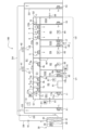
- FIG. 2 is a schematic cross-sectional view of the clean room facility 100. Note that Figure 2 is generally a cross-sectional view taken along line II-II in Figure 1, but in order to clearly show the air flow, the air handling unit 30 as well as the ducts D1 and D2 (see also Figure 1) of the large room R1 are also shown in Figure 2.
- ducts D1 and D2 are air guides through which air exhausted from large room R1 flows, and extend in the vertical direction.
- the air flowing from large room R1 through ducts D1 and D3 in sequence and the air flowing from large room R1 through ducts D2 and D4 in sequence join together, and the joined air is led to the suction side of the air handling unit 30 via duct D5.
- the clean room facility 100 includes an air handling unit 30 (first air handling unit), chambers C1 and C2, a temperature sensor 51, and pressure sensors 61-64.
- the clean room facility 100 also includes dampers 71 and 72 (first dampers), other dampers 81-84 (second dampers), fan filter units 1-8 on the air supply side, and fan filter units 11-18 on the air exhaust side.
- the air handling unit 30 is a device that adjusts the temperature, humidity, etc. of the air supplied to the large room R1 (a specified room). As shown in FIG. 2, the air handling unit 30 includes a filter 31, a cooling coil 32, a fan 33, and an inverter 34.
- the filter 31 collects dust from the air that flows from the large room R1 toward the cooling coil 32 through a duct D5 or the like.
- the cooling coil 32 is a heat exchanger that exchanges heat between the air that has passed through the filter 31 and the refrigerant that flows through a heat transfer tube (not shown). It is also possible to provide the heat exchanger with a humidifying function to adjust the humidity of the air supplied to the large room R1.
- the fan 33 is a blower that sends the air that has been heat exchanged by the cooling coil 32 into the large room R1 through the duct D6.
- the inverter 34 drives the motor (not shown) of the fan 33 in a specified manner.
- the blowing side of the fan 33 and the air outlets H1 and H2 on the ceiling of the large room R1 are connected via a duct D6.
- a filter 41 is installed in the air outlet H1 to collect dust from the air (similar to the other air outlet H2). Note that if the large room R1 is used as a normal room rather than a clean room, there is no particular need to install the filters 41 and 42.
- the air cooled by the air handling unit 30 flows through duct D6 and is then blown out into the large room R1 through the air outlets H1 and H2.
- a damper 10 is installed in the duct D6.
- the damper 10 is set to a predetermined opening during the test run of the air handling unit 30, for example, and is maintained at the above-mentioned predetermined opening during the subsequent air conditioning operation.
- the temperature sensor 51 is a sensor that detects the temperature of the large room R1, and is installed at a specified location in the large room R1. The detected value of the temperature sensor 51 is used to control the air handling unit 30. Although not shown, a humidity sensor may be provided in addition to the temperature sensor 51 so that the temperature and humidity of the large room R1 can be adjusted by the air handling unit 30.
- the pressure sensor 61 is a sensor that detects the chamber pressure in the work chamber R3 and is installed in the work chamber R3. The detection value of the pressure sensor 61 is used to control the fan filter units 11-13 on the exhaust side of the work chamber R3. Note that the fan filter unit 13 (see Figure 1) at the rear of the duct shaft DS2 and the fan filter unit 16 (see Figure 1) at the rear of another duct shaft DS3 are not shown in Figure 2.
- the pressure sensor 62 is a sensor that detects the chamber pressure in the front chamber R2 and is installed in the front chamber R2. The detection value of the pressure sensor 62 is used to control the fan filter unit 14 on the exhaust side of the front chamber R2. The same is true for the remaining pressure sensor 63 in the front chamber R4 and the pressure sensor 64 in the working chamber R5.
- Chamber C1 shown in Figure 2 is the space above the ceiling of the work room R3 and the anteroom R2.
- chamber C1 is provided as a common space above the ceiling of multiple clean rooms such as the work room R3 and the anteroom R2.
- Another chamber C2 shown in Figure 2 is the space above the ceiling of the anteroom R4 and the work room R5.
- These two chambers C1 and C2 are adjacent to each other via a wall W1.
- This wall W1 not only separates chambers C1 and C2, but also, as mentioned above, separates the anterooms R2 and R4, and also separates the work rooms R3 and R5 (see Figure 1).
- the grill G1 shown in FIG. 2 is a member that guides air from the large room R1 to the damper 71 while preventing the damper 71 from being exposed to the large room R1.
- the grill G1 may be configured with multiple blades (louvers) arranged in parallel at a specified interval, or may be configured in a mesh-like manner.
- the gaps between the blades of the grill G1 function as a "first suction port" through which air is sucked in from the large room R1 (a specified room) toward the chamber C1. This "first suction port" is provided near the chamber C1.
- grill G1 is shown on the left side of the page, and another grill G2 is shown on the right side of the page, but grills G1 and G2 may be provided on the front side where doors 24 and 26 (see FIG. 1) are provided.
- Damper 71 switches between communication and blocking between large room R1 (a specified room) and chamber C1.
- This damper 71 is provided on the air inlet side of chamber C1, in a position facing grill G1.
- damper 72 is provided on the air inlet side of another chamber C2.
- These dampers 71 and 72 should preferably be non-leak dampers (airtight dampers) that are highly airtight when closed. In this way, when sterilization is being performed in working rooms R3 and R5 or anterooms R2 and R4, the dampers 71 and 72 can be closed to prevent sterilization gas from flowing into large room R1.
- the dampers 71 and 72 are maintained in the open state during normal use of the clean room facility 100.
- each of the chambers C1 and C2 is connected to the large room R1.
- the air from the large room R1 is led to the chamber C1 through the grill G1 and damper 71 (open state) in sequence.
- the air from the large room R1 is led to the other chamber C2 through the grill G2 and damper 72 (open state) in sequence.
- Chamber C1 is composed of the ceilings of the work chamber R3 and front chamber R2, an upper plate C1a, and a side plate C1b.
- the upper plate C1a is higher than the ceilings of the work chamber R3 and front chamber R2 and is approximately parallel to these ceilings.
- the side plate C1b is a plate that connects the edges of the ceilings of the work chamber R3 and front chamber R2 to the edges of the upper plate C1a and extends in the vertical direction. The same is true for the other chamber C2.
- a structure including multiple clean rooms with a common chamber will be referred to as a "clean unit.”
- a structure including a work chamber R3 and antechamber R2 with a common chamber C1 above the ceiling will be referred to as a first clean unit U1.
- a structure including antechamber R4 and work chamber R5 with a common chamber C2 above the ceiling will be referred to as a second clean unit U2.
- the first clean unit U1 and the second clean unit U2 are adjacent to each other via a wall W1, but they may also be configured to be separated from each other.
- Fan filter units 1-3 shown in Figure 2 are devices that supply air from chamber C1 to work room R3, and are embedded in the ceiling of work room R3.
- Fan filter unit 1 includes supply air fan 1a and filter 1b.
- Supply air fan 1a is a blower that supplies air from chamber C1 to work room R3 (clean room).
- Filter 1b collects dust from the air flowing from supply air fan 1a to work chamber R3 and is provided on the outlet side of supply air fan 1a.
- a HEPA High Efficiency Particulate Air Filter
- ULPA Ultra Low Penetration Air Filter
- the remaining fan filter units 2 and 3 used to supply air to work chamber R3 are also configured in the same way.
- the fan filter unit 4 is a device that supplies air from the chamber C1 to the front room R2.
- the fan filter unit 4 is equipped with an air supply fan 4a and a filter 4b, and is embedded in the ceiling of the front room R2. In this way, an "air supply fan” is provided in each of the multiple “clean rooms.”
- the other fan filter units 5 to 8 on the air supply side are also configured in the same way.
- the fan filter unit 11 shown in FIG. 2 is a device that exhausts air from the work chamber R3, and includes an exhaust fan 11a and a filter 11b.
- the exhaust fan 11a is a blower that exhausts air from the work chamber R3, and is installed in the duct shaft DS1. That is, an opening is provided in a predetermined location on the duct shaft DS1 facing the work chamber R3, and the fan filter unit 11 is fitted into this opening.
- the filter 11b collects dust from the air flowing from the work chamber R3 toward the exhaust fan 11a, and is provided on the suction side of the exhaust fan 11a.
- the other fan filter units 12 to 18 on the exhaust side are configured in the same way.
- the upper end of the duct shaft DS1 is closed and does not communicate with the chamber C1.
- the duct shaft DS1 also communicates with the work room R3 via the exhaust fan 11a. Air is guided from the work room R3 (clean room) to the duct shaft DS1 that does not communicate with the chamber C1, and is exhausted through the duct shaft DS1. In other words, air is exhausted from the work room R3 (clean room) that communicates with the duct shaft DS1 through the duct shaft DS1 that does not communicate with the chamber C1.
- the exhaust destination when exhausting air from the work room R3 through the duct shaft DS1 is the large room R1 (a specified room). The same can be said for exhausting air through the other duct shafts DS2, DS3, and DS4.
- the damper 81 (second damper) shown in FIG. 2 switches between communication and blocking between the duct shaft DS1 and the large room R1 (a specific room), and is provided on the side of the duct shaft DS1 facing the large room R1.
- the damper 82 (second damper) shown in FIG. 2 switches between communication and blocking between the duct shaft DS2 and the large room R1.
- Fan filter unit 12 shown in FIG. 2 and fan filter unit 13 shown in FIG. 1 are devices that exhaust air from work chamber R3 and are installed in duct shaft DS2.
- Another fan filter unit 14 is a device that exhausts air from front chamber R2 and is also installed in duct shaft DS2.
- the duct shaft DS2 is provided in the gap between the work chamber R3 and the front room R2.
- the upper end of this duct shaft DS2 is also closed, so it does not communicate with the chamber C1.
- the duct shaft DS2 also communicates with the work chamber R3 via the exhaust fan 12a, etc., and also communicates with the front room R2 via another exhaust fan 14a.
- the air in the work chamber R3 and the front room R2 is exhausted to the large room R1 through the duct shaft DS2 and the damper 82 (open state) in sequence (see also Figure 1).
- the downward arrow near the damper 82 in Figure 2 indicates the flow of air toward the large room R1.
- the fan filter units 1-8 on the intake side and the fan filter units 11-18 on the exhaust side are controlled by a control device (not shown). Note that each of the fan filter units 1-8 and 11-18 may have a built-in control device, or multiple fan filter units may be connected to a single control device via wiring.
- the rotation speed of exhaust fans 11a, 12a, 13a is controlled, for example, to maintain the room pressure in work chamber R3 at a predetermined set pressure (target pressure).
- the rotation speed of supply fans 1a, 2a, 3a may be constant or may be adjusted appropriately based on the room pressure in work chamber R3.
- the clean room facility 100 is generally symmetrical with respect to wall W1, a description of the configuration related to air conditioning in antechamber R4 and work chamber R5 will be omitted.
- FIG. 8 is a schematic cross-sectional view of a clean room facility 200 according to a comparative example.
- the comparative example of Fig. 8 differs from the first embodiment (see Fig. 2) in that no damper is provided, and that duct shafts DS1 and DS2 communicate with chamber C1, while duct shafts DS3 and DS4 communicate with another chamber C2.
- the comparative example of Fig. 8 also differs from the first embodiment in that duct shafts DS1 and DS4 do not communicate with large room R1.
- the comparative example of Fig. 8 also differs from the first embodiment (see Fig. 2) in that duct shaft DS2 communicates with large room R1 through opening A1, and the remaining duct shaft DS3 communicates with large room R1 through another opening A2.
- the duct shafts DS1 and DS2 of the clean unit U1 include those that do not communicate with the chamber C1.
- neither of the duct shafts DS1 and DS2 communicate with the chamber C1.
- the same can be said for the duct shafts DS3 and DS4 of the other clean unit U2.
- the air handling unit 30, the fan filter units 1-8 on the air supply side, and the fan filter units 11-18 on the air exhaust side are driven in a predetermined manner.
- the damper 71 on the air inlet side of the chamber C1 is open, and the large room R1 and the chamber C1 communicate with each other through the damper 71 (similar to the other damper 72).
- the damper 81 provided on the duct shaft DS1 is open, and the duct shaft DS1 and the large room R1 communicate with each other through the damper 81 (similar to the other dampers 82-84).
- part of the air led from the large room R1 to the chamber C1 via the damper 71 is led to the work room R3, and part of the air in the work room R3 is exhausted to the large room R1 via the duct shaft DS1 and damper 81 in sequence.
- the work room R3 can be conditioned with high efficiency. The same can be said for the air conditioning of the other antechambers R2, R4 and the work room R5.
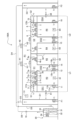
- FIG. 3 is an explanatory diagram showing an example of a process during sterilization of the working chamber R3 and the anterior chamber R2.
- the sterilization gas generator 91 shown in Fig. 3 is a device that generates a specified sterilization gas (hydrogen peroxide gas, etc.).
- the sterilization gas generator 91 is arranged in the working room R3, and when the sterilization gas generator 91 is driven with all the doors closed, the sterilization gas generator 91 generates a sterilization gas.
- chambers C1 and C2 are separated by wall W1, for example, sterilization gas generated by sterilization gas generator 91 does not flow from working chamber R3 through chamber C1 into the adjacent chamber C2. Therefore, even during sterilization of working chamber R3 or antechamber R2, there is no problem if the fan filter units 15-18 on the air supply side and the fan filter units 15-18 on the exhaust side of the other antechamber R4 and working chamber R5 continue to be driven, and there is also no problem if dampers 72, 83, and 84 remain open.
- the fan filter units 1-4 on the air supply side in the chamber C1 are kept stopped, and the fan filter units 11-14 that exhaust air from the working chamber R3 and the front chamber R2 are also kept stopped.
- the damper 71 (first damper) and dampers 81, 82 (second dampers) are kept closed.
- the sterilizing gas filling the working chamber R3 flows into the chamber C1 through the stopped air supply side fan filter units 1-3, and further flows into the front chamber R2 through the remaining air supply side fan filter unit 4.
- the sterilizing gas filling the working chamber R3 also flows into the duct shaft DS1 through the stopped exhaust side fan filter unit 11, and also flows into the duct shaft DS2 through the fan filter unit 12, etc.
- the sterilizing gas flows into the front chamber R2 through the exhaust side fan filter unit 14 from the duct shaft DS2.
- the sterilizing gas generator 91 in one clean room (working chamber R3 in the example of Figure 3), the working chamber R3, front chamber R2, and duct shafts DS1 and DS2, which share the common chamber C1, can be sterilized all at once.
- the damper 71 on the air inlet side of chamber C1 is closed, blocking the communication between large room R1 and chamber C1. This prevents sterilized gas from leaking from chamber C1 to large room R1.
- the damper 81 provided on duct shaft DS1 is also closed, blocking the communication between large room R1 and duct shaft DS1. This prevents sterilized gas from leaking into large room R1 through duct shaft DS1. Similarly, sterilized gas can be prevented from leaking into large room R1 through the other duct shaft DS2.
- a sterilization gas generator 91 may be placed in the anterior chamber R2. Also, a sterilization gas generator 91 may be placed in each of the working chamber R3 and the anterior chamber R2. In short, when sterilizing multiple clean rooms, it is advisable to place a sterilization gas generator 91 in at least one of the multiple clean rooms.
- the air handling unit 30 and fans F1, F2 running even during sterilization of the work room R3 or the front room R2. This allows the large room R1 to be maintained at a specified temperature even during sterilization.
- the fan filter units 5-8, 15-18 can be kept running to air-condition the front room R4 and work room R5, which have chambers C2 different from the chamber C1 in the ceiling above the work room R3, even during sterilization of the work room R3, etc. Therefore, work such as sample preparation can continue to be carried out in the front room R4 and work room R5.
- FIG. 4 is an explanatory diagram showing another example of the process during sterilization of the working chamber R3 and the anterior chamber R2.
- a sterilization gas generator 92 may be disposed outside the working chamber R3 (inside the large room R1 or outside the large room R1), and sterilization gas may be supplied from this sterilization gas generator 92 to the working chamber R3 via a hose 93. That is, when multiple clean rooms such as the working chamber R3 and the anteroom R2 are to be sterilized, sterilization gas may be supplied from the sterilization gas generator 92 to at least one of the multiple clean rooms from the outside via the hose 93. With this configuration, the same effects as in Fig. 3 can be achieved.
- an exhaust hose (not shown) for exhausting air from the working chamber R3 may be connected to the sterilization gas generator 92.
- air that has been rendered harmless by catalytic gas air in which the concentration of sterilization gas is equal to or lower than a predetermined value
- the exhaust hose (not shown).
- sterilization gas or the like may be circulated via a predetermined pipe or duct.
- a decomposition device (not shown) equipped with a specified catalytic filter (not shown) that renders the sterilization gas harmless may be provided separately.
- a catalytic filter may be provided downstream of the dampers 81 and 82 on the exhaust side to reduce the concentration of the sterilization gas by the catalyst.
- the working chamber R3 can be appropriately conditioned, and the efficiency of air conditioning when cooling the working chamber R3 is improved. The same can be said about the air conditioning of the other anterior chambers R2, R4 and the working chamber R5.
- the anterooms R2 and R4 and the workrooms R3 and R5 are provided inside the large room R1, it becomes easier to, for example, add a new clean room inside the large room R1 or change the layout.
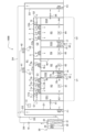
- FIG. 5 is a schematic cross-sectional view of a clean room facility 100A according to a first modified example of the first embodiment.
- the clean room facility 100A shown in Fig. 5 differs from the first embodiment (see Fig. 2) in that the duct shaft DS2 communicates with the chamber C1 and the duct shaft DS3 communicates with another chamber C2.
- the clean room facility 100A shown in Fig. 5 also differs from the first embodiment in that no dampers are provided in the duct shafts DS2 and DS3, and neither of the duct shafts DS2 and DS3 communicates with the large room R1. Other points are the same as those in the first embodiment, so a description of the overlapping parts will be omitted.
- the duct shaft DS2 is connected to the chamber C1, but the other duct shafts DS1 are not connected to the chamber C1. Therefore, at least in the flow path via the duct shaft DS1, the occurrence of a closed-loop air flow can be suppressed. Similarly, in the flow path via the duct shaft DS4 of the second clean unit U2, a closed-loop air flow hardly occurs. Therefore, although the air conditioning efficiency is slightly inferior to the first embodiment, the working room R3 and the like can be appropriately air-conditioned.
- the air that flows into the duct shaft DS2 from the work chamber R3 is returned (returned) to the chamber C1 via the duct shaft DS2. Therefore, the highly clean air supplied to the chamber C1 can be reused.
- duct shaft DS1 may be connected to chamber C1
- another duct shaft DS4 may be connected to chamber C2
- the remaining duct shafts DS2, DS3 may not be connected to chambers C1, C2.
- air conditioning of the work room R3, etc. can be performed appropriately.
- the configuration includes at least one duct shaft that is not connected to chambers C1, C2 among the multiple duct shafts DS1, DS2, DS3, DS4.
- no dampers are installed in the duct shafts DS2 and DS3 that communicate with the chamber C1, but this is not limited to the above. That is, a damper (not shown) may be installed in each of the duct shafts DS2 and DS3. In this case, for example, a portion of the air that flows into the duct shaft DS2 from the work room R3 is returned to the chamber C1 via the duct shaft DS2, and the remaining air is led to the large room R1 via an open damper (not shown). Even with this configuration, clean air can be reused while properly conditioning each clean room such as the work room R3.
- FIG. 6 is a schematic cross-sectional view of a clean room facility 100B according to a second modified example of the first embodiment. 6 differs from the first embodiment in that the duct shaft DS1 is not provided with an exhaust fan filter unit, but instead has an opening A3 (the same applies to the other duct shafts DS4). Other points are similar to those in the first embodiment, so descriptions of overlapping parts will be omitted.
- an opening A3 is provided on the work chamber R3 side of the duct shaft DS1. Air is exhausted from the work chamber R3 through the opening A3, duct shaft DS1, and damper 81 (open) in that order to the large room R1. The same applies to exhaust through duct shaft DS4.
- the positions of the openings A3 and A4 are not limited to the example in FIG. 6, and some or all of the exhaust fans 11a to 18a (see FIG. 2) described in the first embodiment may be omitted, and openings may be provided in the omitted locations. Filters may also be installed in each of these openings as appropriate.
- the second embodiment differs from the first embodiment in that a first clean unit U3 (see FIG. 7) having a predetermined chamber C3 and a second clean unit U4 (see FIG. 7) having another chamber C4 are provided separately from each other.
- the second embodiment also differs from the first embodiment in that an air handling unit 9 (see FIG. 7) that individually conditions the air for the second clean unit U4 is provided.
- the rest of the second embodiment is similar to the first embodiment. Therefore, only the parts that differ from the first embodiment will be described, and the explanation of the overlapping parts will be omitted.
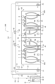
- FIG. 7 is a schematic cross-sectional view of a clean room facility 100C according to the second embodiment.
- the clean room facility 100C includes a first clean unit U3, a second clean unit U4, and an air handling unit 9 (second air handling unit).
- the first clean unit U3 includes a work room R3 and an antechamber R2 as a plurality of clean rooms that share a chamber C3 in common.
- the second clean unit U4 includes a work room R5 and an antechamber R4 as a plurality of clean rooms that share a chamber C4 in common.
- the first clean unit U3 and the second clean unit U4 are provided inside a large room R1 (a specified room).
- R1 a specified room
- the configuration of the first clean unit U3 is similar to that of the first clean unit U1 (see FIG. 2) described in the first embodiment, so a description thereof will be omitted.
- the second clean unit U4 has a configuration generally similar to that of the first clean unit U3.
- the second clean unit U4 differs from the first clean unit U3 in that a grill is not provided upstream of the damper 72, and instead a wall W3 is provided.
- the downstream end of a duct D7, through which air cooled by the air handling unit 9 flows, is inserted into this wall W3. It is also possible to configure the downstream end of the duct D7 to be directly connected to the damper 72.
- the second clean unit U4 has a larger air conditioning load than the first clean unit U3. For example, if the amount of heat generated by equipment (not shown) installed in the workroom R5, etc. is large, or if the set temperature (target temperature) of the workroom R5, etc. is lower than that of the workroom R3, etc. of the first clean unit U3, the air conditioning load of the second clean unit U4 will often be relatively large. Therefore, in the second embodiment, the air in the large room R1 is additionally cooled by the air handling unit 9 before being supplied to the second clean unit U4.
- the air handling unit 9 is an air conditioner that draws in air from the large room R1 (a specified room), adjusts the temperature, and supplies the temperature-adjusted air to the chamber C4 of the second clean unit U4.
- the air handling unit 9 is equipped with a filter 9a, a cooling coil 9b, a fan 9c, and an inverter 9d.
- the configuration of the air handling unit 9 shown in FIG. 7 is similar to that of another air handling unit 30 for cooling the air in the large room R1, so a description thereof will be omitted.
- the air drawn into the air handling unit 9 from the large room R1 is cooled to a specified degree, and the cooled air is led to the chamber C4 via the duct D7 and the damper 72 (open state) in sequence.
- a damper 10a is installed in duct D7.
- Damper 10a is set to a predetermined opening degree, for example, during a trial run of air handling unit 9, and is maintained at the predetermined opening degree during subsequent air conditioning operation.
- the opening degree of damper 10a may be adjusted as appropriate based on the air conditioning load of front room R4 and work room R5.
- the working room R3 and the anteroom R2 are maintained at a predetermined set temperature by directly supplying the air from the large room R1 (i.e., the air cooled by the air handling unit 30) to the first clean unit U3. Therefore, for the first clean unit U3, there is no particular need to provide an air handling unit for individual air conditioning.
- the air handling unit 9 is configured to suck in the air of the large room R1, but this is not limited thereto.
- the air handling unit 9 may be configured to selectively suck in the air of the large room R1 and the air of the work room R5 based on the temperature information of the large room R1 and the temperature information of the work room R5.
- the air handling unit 9 when the air handling unit 9 performs cooling operation, when the temperature of the work room R5 is lower than the temperature of the large room R1, the air handling unit 9 is configured to suck in the air of the work room R5. Also, when the temperature of the large room R1 is lower than the temperature of the work room R5, the air handling unit 9 is configured to suck in the air of the large room R1. This reduces the air conditioning load of the air handling unit 9, thereby achieving energy conservation.
- the target for the air handling unit 9 to suck in the air may be either the large room R1 or the work room R5.
- air further cooled by the air handling unit 9 is supplied to the chamber C4 of the second clean unit U4. Therefore, even if the air conditioning load of the second clean unit U4 is larger than that of the first clean unit U3, air conditioning suitable for the usage environment of the second clean unit U4 can be performed individually.
- the large room R1 and the first clean unit U3 can also be appropriately air-conditioned by a separate air handling unit 30.
- a predetermined gap is provided between the ceiling of the large room R1 and the upper plate C1a of the chamber C1, and between the ceiling of the large room R1 and the upper plate C2a of the chamber C2, but this is not limited to the above.
- the upper plates C1a, C2a may be integrated into the ceiling of the large room R1.
- the side walls of the first clean unit U1, etc. may be integrated into part of the side walls of the large room R1.
- the exhaust destination from the clean room such as the working room R3 is the large room R1
- the exhaust destination from the clean room such as the working room R3 may be a space outside the clean room facility 100.
- the number of clean room units is two, but the present invention is not limited to this. That is, the large room R1 (predetermined room) may be configured to have at least one clean room unit.
- the dampers 81 to 84 are provided to correspond to the duct shafts DS1, DS2, DS3, and DS4, but the present invention is not limited to this.
- the dampers 81 to 84 may be omitted, and a specific duct shaft may communicate with the large room R1 via an exhaust port (second exhaust port: not shown).
- an operator may cover the exhaust port so that sterilization gas does not flow into the large room R1 via the exhaust port.
- the sterilization gas generators 91, 92 (see Figs. 3 and 4) that generate sterilization gas are provided, but the present invention is not limited to this.
- a device having an aeration function using a catalyst or the like in addition to the functions of dehumidification and predetermined gas generation may be provided.
- the sterilization gas generators 91, 92 may also have these functions.
- the air in the large room R1 (see FIG. 2) is guided to the air handling unit 30, and the air cooled by the air handling unit 30 is returned to the large room R1, but this is not limited to the above.
- an air handling unit (not shown) outdoors in the clean room facility may take in outside air, and the air cooled by this air handling unit may be guided to the large room R1.
- the exhaust destination from a specified clean room may be outdoors.
- the layout of the clean room facility 100 etc. described in each embodiment is one example, but other layouts may also be configured as follows. That is, the clean room facility may be provided with duct shafts that are provided in the gaps between the clean rooms among the multiple clean rooms and/or in the gaps between a specific clean room and the large room R1 (specific room). Also, one or more duct shafts may be provided on the outside of the side wall of at least one clean room. In such a configuration, the one or more duct shafts include one that is not connected to the chamber. This allows air to be exhausted from the specific clean room to the large room R1 etc. via the duct shaft that is not connected to the chamber, thereby preventing air from circulating in a closed loop.
- the duct shafts DS1, DS2, DS3, and DS4 may be arranged in a straight line along a specific side wall facing the large room R1. This allows workers to open the maintenance covers (not shown) of the duct shafts DS1, DS2, DS3, and DS4 to expose the fan filter units 11-18, and work sequentially along the side wall, making maintenance work easier.
- a porous plate or grating may be provided at the upper end (downstream end of the air flow) of the duct shaft DS2.
- a porous plate or grating may be provided at the upper end (downstream end of the air flow) of the duct shaft DS2.
- Such a configuration is also included in the matter of the duct shaft DS2 being in communication with the chamber C1.
- the air handling unit 9 individually performs air conditioning for the second clean unit U4, but this is not limited to the above. That is, two air handling units 9 (second air handling units) may be installed inside the large room R1 so as to correspond one-to-one to the first clean unit U3 and the second clean unit U4. The air in the large room R1 may then be cooled by each air handling unit 9, and the cooled air may be guided to the chambers C3 and C4. With this configuration, even if the set temperatures of the first clean unit U3 and the second clean unit U4 are different from that of the large room R1, the air handling units 9 can assist in air conditioning.
- a duct shaft may be provided in the gap between the side wall of the large room R1 and a specified clean room.
- a duct shaft may not communicate with the chamber C1, and furthermore, air may be exhausted from the clean room to the outside of the large room R1 via the duct shaft.
- the damper 71 (see FIG. 2) is hidden by the grill G1 when viewed from inside the large room R1, and another damper 72 (see FIG. 2) is hidden by the grill G2, but this is not limiting.
- the grills G1 and G2 may be omitted as appropriate, and the dampers 71 and 72 may be exposed to the large room R1.
- a configuration has been described in which the damper 81 is provided on the large room R1 side of the duct shaft DS1 (the main body of the damper 81 is exposed to the large room R1), but this is not limited to the above.
- the damper 81 may be installed inside the duct shaft DS1. This makes the damper 81 hidden when viewed from inside the large room R1, improving the design. The same applies to the other dampers 82 to 84.
- the air outlets H1, H2 first air outlets: see FIG. 1
- the air handling unit 30 first air handling unit
- the air outlets H1, H2 are provided upstream in the air flow direction relative to the intake ports (first intake ports: gaps in the grills G1, G2) near the chambers C1, C2.
- the conditioned air blown out from the outlets H1, H2 is led directly to the chamber C1 via the intake port, so that cooled air can be sent to the front rooms R2, R4 and the work rooms R3, R5.
- a damper 81 (second damper) or a second exhaust port (not shown) that guides the air exhausted from the duct shaft DS1 (see FIG. 2) to the large room R1 (a specified room) may be provided on the duct shaft DS1.
- an intake port H3 (second intake port: see FIG. 1) that draws in air from the large room R1 toward the air handling unit 30 (first air handling unit) may be provided on the duct D1 (see FIG. 1).
- an intake port H3 (second intake port) is provided downstream of the damper 81 (second damper) or the second exhaust port in the air flow direction.
- the chambers C1 and C2 are described as being separated by a wall W1, but this is not limited thereto.
- the wall W1 may not be provided, and the chambers C1 and C2 may be one common space.
- the clean rooms such as the work chambers R3 and R5 and the anterooms R2 and R4 are described as being used as positive pressure rooms, but depending on the application, the clean rooms may be used as negative pressure rooms.
- the clean room facility 100 and the like are described as being used for cell culture processing and pharmaceutical manufacturing, but this is not limited to this.
- each embodiment can be applied to various fields such as the manufacturing of semiconductors, precision machinery, and liquid crystal panels, the food industry, the cosmetics industry, and experiments using radioactive materials.
Landscapes
- Engineering & Computer Science (AREA)
- Chemical & Material Sciences (AREA)
- General Engineering & Computer Science (AREA)
- Mechanical Engineering (AREA)
- Combustion & Propulsion (AREA)
- Health & Medical Sciences (AREA)
- Animal Behavior & Ethology (AREA)
- General Health & Medical Sciences (AREA)
- Public Health (AREA)
- Veterinary Medicine (AREA)
- Life Sciences & Earth Sciences (AREA)
- Epidemiology (AREA)
- General Chemical & Material Sciences (AREA)
- Chemical Kinetics & Catalysis (AREA)
- Ventilation (AREA)
Priority Applications (4)
| Application Number | Priority Date | Filing Date | Title |
|---|---|---|---|
| US19/111,366 US20260104171A1 (en) | 2023-02-10 | 2023-02-10 | Clean room facility |
| JP2024576034A JPWO2024166344A1 (enExample) | 2023-02-10 | 2023-02-10 | |
| PCT/JP2023/004512 WO2024166344A1 (ja) | 2023-02-10 | 2023-02-10 | クリーンルーム施設 |
| TW112141451A TWI893499B (zh) | 2023-02-10 | 2023-10-30 | 無塵室設施 |
Applications Claiming Priority (1)
| Application Number | Priority Date | Filing Date | Title |
|---|---|---|---|
| PCT/JP2023/004512 WO2024166344A1 (ja) | 2023-02-10 | 2023-02-10 | クリーンルーム施設 |
Publications (1)
| Publication Number | Publication Date |
|---|---|
| WO2024166344A1 true WO2024166344A1 (ja) | 2024-08-15 |
Family
ID=92262262
Family Applications (1)
| Application Number | Title | Priority Date | Filing Date |
|---|---|---|---|
| PCT/JP2023/004512 Ceased WO2024166344A1 (ja) | 2023-02-10 | 2023-02-10 | クリーンルーム施設 |
Country Status (4)
| Country | Link |
|---|---|
| US (1) | US20260104171A1 (enExample) |
| JP (1) | JPWO2024166344A1 (enExample) |
| TW (1) | TWI893499B (enExample) |
| WO (1) | WO2024166344A1 (enExample) |
Citations (7)
| Publication number | Priority date | Publication date | Assignee | Title |
|---|---|---|---|---|
| JPS63116037A (ja) * | 1986-11-03 | 1988-05-20 | Hirayama Setsubi Kk | クリーンルームシステム用ユニット |
| JPH08327106A (ja) * | 1995-05-31 | 1996-12-13 | Taikisha Ltd | クリーンルーム設備 |
| JPH10277339A (ja) * | 1997-02-07 | 1998-10-20 | Fuji Electric Co Ltd | クリーンルームのファンフィルタユニット |
| JP2006036266A (ja) * | 2004-07-27 | 2006-02-09 | Daiwa Can Co Ltd | 製造設備 |
| JP2011257019A (ja) * | 2010-06-05 | 2011-12-22 | Takenaka Komuten Co Ltd | クリーンルーム区画ユニット及びクリーンルーム区画方法 |
| JP2014070748A (ja) * | 2012-09-27 | 2014-04-21 | Dainippon Printing Co Ltd | クリーンルームの区画方法、クリーンルーム |
| WO2022254705A1 (ja) * | 2021-06-04 | 2022-12-08 | 日立グローバルライフソリューションズ株式会社 | 空調システム |
Family Cites Families (6)
| Publication number | Priority date | Publication date | Assignee | Title |
|---|---|---|---|---|
| JP3835883B2 (ja) * | 1997-04-25 | 2006-10-18 | 株式会社大気社 | 清浄空気吹出ユニット、及び、クリーンルーム |
| JP4221539B2 (ja) * | 2000-06-23 | 2009-02-12 | 株式会社日立プラントテクノロジー | クリーンルーム設備 |
| JP2016142448A (ja) * | 2015-02-02 | 2016-08-08 | パナソニックIpマネジメント株式会社 | ファンフィルタユニットシステム |
| CN211286806U (zh) * | 2019-11-05 | 2020-08-18 | 深圳市冠航环境科技工程有限公司 | 一种布袋送风的洁净室 |
| CA3150088C (en) * | 2019-12-04 | 2023-10-10 | Mitsuru SEKIZAWA | Air conditioning system |
| CN111829103A (zh) * | 2020-08-19 | 2020-10-27 | 江苏博创翰林光电高科技有限公司 | 分布式节能型恒温洁净室 |
-
2023
- 2023-02-10 JP JP2024576034A patent/JPWO2024166344A1/ja active Pending
- 2023-02-10 WO PCT/JP2023/004512 patent/WO2024166344A1/ja not_active Ceased
- 2023-02-10 US US19/111,366 patent/US20260104171A1/en active Pending
- 2023-10-30 TW TW112141451A patent/TWI893499B/zh active
Patent Citations (7)
| Publication number | Priority date | Publication date | Assignee | Title |
|---|---|---|---|---|
| JPS63116037A (ja) * | 1986-11-03 | 1988-05-20 | Hirayama Setsubi Kk | クリーンルームシステム用ユニット |
| JPH08327106A (ja) * | 1995-05-31 | 1996-12-13 | Taikisha Ltd | クリーンルーム設備 |
| JPH10277339A (ja) * | 1997-02-07 | 1998-10-20 | Fuji Electric Co Ltd | クリーンルームのファンフィルタユニット |
| JP2006036266A (ja) * | 2004-07-27 | 2006-02-09 | Daiwa Can Co Ltd | 製造設備 |
| JP2011257019A (ja) * | 2010-06-05 | 2011-12-22 | Takenaka Komuten Co Ltd | クリーンルーム区画ユニット及びクリーンルーム区画方法 |
| JP2014070748A (ja) * | 2012-09-27 | 2014-04-21 | Dainippon Printing Co Ltd | クリーンルームの区画方法、クリーンルーム |
| WO2022254705A1 (ja) * | 2021-06-04 | 2022-12-08 | 日立グローバルライフソリューションズ株式会社 | 空調システム |
Also Published As
| Publication number | Publication date |
|---|---|
| TW202432993A (zh) | 2024-08-16 |
| US20260104171A1 (en) | 2026-04-16 |
| TWI893499B (zh) | 2025-08-11 |
| JPWO2024166344A1 (enExample) | 2024-08-15 |
Similar Documents
| Publication | Publication Date | Title |
|---|---|---|
| US7251953B2 (en) | Environmental control unit for hospital room | |
| EP4071415B1 (en) | Air conditioning system | |
| JP7491773B2 (ja) | 給排気システム及びクリーンルームシステム | |
| TWI893301B (zh) | 空調系統 | |
| TWI911489B (zh) | 無塵室設施 | |
| JP2012202558A (ja) | クリーンルーム空調システム | |
| JP3410389B2 (ja) | クリーンルーム | |
| JP4374294B2 (ja) | 安全キャビネット | |
| WO2024166344A1 (ja) | クリーンルーム施設 | |
| JP4486727B2 (ja) | 循環型クリーンルーム | |
| JP3516507B2 (ja) | クリーンルームシステム | |
| JP2021162210A (ja) | 微生物を制御する室の空調システム | |
| JP2019143933A (ja) | クリーンルーム及びクリーンルームの排気量調整方法 | |
| JPH07250870A (ja) | 無菌病室 | |
| KR102683004B1 (ko) | 실내 멸균 벤틸레이션 방법 및 실내 멸균 벤틸레이션 시스템 | |
| JP7825739B2 (ja) | クリーンルーム施設 | |
| JPH0132557Y2 (enExample) | ||
| JP3521801B2 (ja) | クリーンルーム設備 | |
| CN105689025A (zh) | 一种具有热交换功能的生物安全柜 | |
| KR20220060885A (ko) | 안티바이러스 전열교환 환기시스템 | |
| KR102532434B1 (ko) | 환기 장치 | |
| JPWO2024166344A5 (enExample) | ||
| TWI913696B (zh) | 無塵室設施 | |
| CN205517813U (zh) | 一种具有热交换功能的生物安全柜 | |
| CN212901865U (zh) | 一种用于门诊室的空调通风系统 |
Legal Events
| Date | Code | Title | Description |
|---|---|---|---|
| 121 | Ep: the epo has been informed by wipo that ep was designated in this application |
Ref document number: 23920306 Country of ref document: EP Kind code of ref document: A1 |
|
| WWE | Wipo information: entry into national phase |
Ref document number: 2024576034 Country of ref document: JP |
|
| NENP | Non-entry into the national phase |
Ref country code: DE |
|
| 122 | Ep: pct application non-entry in european phase |
Ref document number: 23920306 Country of ref document: EP Kind code of ref document: A1 |