WO2024166235A1 - フィーダ管理装置 - Google Patents
フィーダ管理装置 Download PDFInfo
- Publication number
- WO2024166235A1 WO2024166235A1 PCT/JP2023/004105 JP2023004105W WO2024166235A1 WO 2024166235 A1 WO2024166235 A1 WO 2024166235A1 JP 2023004105 W JP2023004105 W JP 2023004105W WO 2024166235 A1 WO2024166235 A1 WO 2024166235A1
- Authority
- WO
- WIPO (PCT)
- Prior art keywords
- feeder
- unit
- bulk
- component mounting
- management device
- Prior art date
- Legal status (The legal status is an assumption and is not a legal conclusion. Google has not performed a legal analysis and makes no representation as to the accuracy of the status listed.)
- Ceased
Links
Images



Classifications
-
- H—ELECTRICITY
- H05—ELECTRIC TECHNIQUES NOT OTHERWISE PROVIDED FOR
- H05K—PRINTED CIRCUITS; CASINGS OR CONSTRUCTIONAL DETAILS OF ELECTRIC APPARATUS; MANUFACTURE OF ASSEMBLAGES OF ELECTRICAL COMPONENTS
- H05K13/00—Apparatus or processes specially adapted for manufacturing or adjusting assemblages of electric components
- H05K13/08—Monitoring manufacture of assemblages
- H05K13/086—Supply management, e.g. supply of components or of substrates
-
- H—ELECTRICITY
- H05—ELECTRIC TECHNIQUES NOT OTHERWISE PROVIDED FOR
- H05K—PRINTED CIRCUITS; CASINGS OR CONSTRUCTIONAL DETAILS OF ELECTRIC APPARATUS; MANUFACTURE OF ASSEMBLAGES OF ELECTRICAL COMPONENTS
- H05K13/00—Apparatus or processes specially adapted for manufacturing or adjusting assemblages of electric components
- H05K13/04—Mounting of components, e.g. of leadless components
- H05K13/043—Feeding one by one by other means than belts
Definitions
- the present invention relates to a feeder management device.
- the feeder management device manages bulk feeders.
- Bulk feeders are installed in component mounting machines that mount components on a board and are used to supply components. As shown in Patent Document 1, the bulk feeder supplies components in a bulk state in a supply area where the suction nozzle of the component mounting machine can pick up the components.
- maintenance such as removing the parts remaining in the feeder is performed as appropriate.
- Some types of bulk feeders have a transport unit that forms the part transport path and is detachable from the feeder body. While this type of feeder improves maintainability, there is a concern that the installation process may not be performed correctly if the feeder body and transport unit are not combined correctly.
- the purpose of this specification is to provide a feeder management device that manages the bulk feeders installed in a component mounting machine, including the transport units, and supports the execution of normal mounting processing.
- This specification discloses a feeder management device that includes an acquisition unit that acquires the feeder ID of a bulk feeder equipped in a component mounting machine and the unit ID of a transport unit that is detachably set in the feeder body of the bulk feeder and forms a transport path for components, and a determination unit that determines whether to permit or restrict the application of the bulk feeder to the mounting process by the component mounting machine based on the feeder ID and unit ID acquired by the acquisition unit.
- the bulk feeder installed in the component mounting machine can be managed, including the transport unit set in the bulk feeder, and normal mounting processing can be supported.
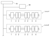
- FIG. 1 is a schematic diagram showing a production system to which a feeder management device and a setup device are applied;
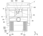
- FIG. 2 is a plan view showing a schematic diagram of the component mounting machine;
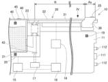
- FIG. 2 is a side view showing a schematic of a portion of a bulk feeder including a feeding area.
- FIG. 4 is a plan view seen from the direction IV in FIG. 3 .
- FIG. 2 is a perspective view showing the appearance of a transport unit and a setup device that constitute the bulk feeder.
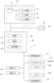
- FIG. 2 is a block diagram showing a setup device.
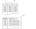
- FIG. 13 is a diagram showing unit information, feeder information, and case information. 13 is a flowchart showing a feeder management process.
- Feeder management device 80 manages feeders that supply components to component mounting machine 2.
- feeder management device 80 is incorporated into host computer 70, which serves as a host device that manages control device 96 of component mounting machine 2 and a plurality of substrate-related operation machines including component mounting machine 2.
- Feeder management device 80 manages bulk feeders 10, which are a type of feeder.
- the component mounting machine 2 described above performs a mounting process for mounting components on a board as a specified substrate-related operation.
- the production line Ln is configured by installing a plurality of substrate-related operation machines in the conveying direction of the board. Each of the substrate-related operation machines is communicatively connected to a host computer 70 that controls the production line Ln as a whole.
- the production line Ln includes a printing machine 1 as a plurality of substrate-related operation machines, a plurality of component mounting machines 2, a reflow furnace 3, and an inspection machine 4.
- the printer 1 prints solder paste at the component mounting positions on the board that has been brought in.
- Each of the multiple component mounting machines 2 mounts components on the board transported from the upstream side of the production line Ln. The configuration of the component mounting machines 2 will be described later.
- the reflow furnace 3 heats the board transported from the upstream side of the production line Ln to melt the solder on the board and perform soldering.
- the inspection machine 4 inspects whether the appearance or function of the board products produced on the production line Ln is normal.
- a factory for substrate products may be configured with multiple production lines Ln (Ln1, Ln2, ).
- Each of the multiple production lines Ln may have its configuration added or changed as appropriate, for example, depending on the type of substrate product being produced.
- the multiple production lines Ln may be appropriately equipped with substrate-related work machines such as a buffer device for temporarily holding the substrates being transported, a substrate supply device, a substrate inversion device, various inspection devices, a shield mounting device, an adhesive application device, and an ultraviolet irradiation device.
- the setup device 50 is used for tasks such as loading components into a feeder to be used in a planned mounting process and removing components from a feeder that has been used in a mounting process.
- the setup device 50 has a support stand 51 that supports the feeder or some of the units that have been removed from the feeder.
- the setup device 50 is connected to a host computer 70 so that it can communicate with it, and inputs and outputs various information related to the setup. The detailed configuration of the setup device 50 will be described later.
- the component mounting machine 2 includes a board transport device 91.
- the board transport device 91 sequentially transports the board B in a transport direction and positions the board B at a predetermined position within the machine.
- the component mounting machine 2 includes a component supplying device 92.
- the component supplying device 92 supplies components to be mounted on the board B.
- the component supplying device 92 has feeders 922 set in a plurality of slots 921.
- the feeders 922 may be, for example, a tape feeder that feeds and moves a carrier tape containing a large number of components to supply the components so that they can be picked.
- the feeders 922 may be, for example, a bulk feeder 10 that supplies components stored in a bulk state so that they can be picked. Details of the bulk feeder 10 will be described later.
- the component mounting machine 2 includes a component transfer device 93.
- the component transfer device 93 transfers the components supplied by the component supply device 92 to a predetermined mounting position on the board B.
- the component transfer device 93 includes a head drive device 931, a movable table 932, a mounting head 933, and a suction nozzle 934.
- the head drive device 931 moves the movable table 932 in the horizontal direction (X direction and Y direction) by a linear motion mechanism.
- the mounting head 933 is detachably fixed to the movable table 932 by a clamp member (not shown) and is provided so as to be movable horizontally within the machine.
- the mounting head 933 supports multiple suction nozzles 934 so that they can rotate and rise and fall.
- the suction nozzles 934 are holding members that pick up and hold the parts supplied by the feeder 922.
- the suction nozzles 934 use the supplied negative pressure air to pick up the parts supplied by the feeder 922.
- a chuck that holds the parts by gripping them can be used as the holding member attached to the mounting head 933.
- the component mounting machine 2 includes a component camera 94 and a board camera 95.
- the component camera 94 and the board camera 95 are digital imaging devices having imaging elements such as CMOS.
- the component camera 94 and the board camera 95 capture images based on a control signal and send image data acquired by the imaging.
- the component camera 94 is configured to be able to capture images of the components held by the suction nozzle 934 from below.
- the board camera 95 is provided on the moving stage 932 so as to be movable in the horizontal direction integrally with the mounting head 933.
- the board camera 95 is configured to be able to capture images of the board B from above.
- the board camera 95 can also capture various devices within the movable range of the movable stage 932.
- the board camera 95 can capture images of the supply area As to which the bulk feeder 10 supplies components and the reference mark 39 provided on the top of the bulk feeder 10 within the camera's field of view. In this way, the board camera 95 can be used to capture images of different objects in order to obtain image data to be used for various image processing.
- Control device 96 As shown in Fig. 2, the component mounting machine 2 includes a control device 96.
- the control device 96 is mainly composed of a CPU, various memories, a control circuit, and a storage device.
- the control device 96 stores various data such as a control program used to control the mounting process.
- the control program indicates the mounting positions, mounting angles, and component types of components to be mounted on the board B in the mounting process in a scheduled mounting order.
- the control device 96 executes a process for recognizing the holding state of the components held by each of the multiple holding members (suction nozzles 934). Specifically, the control device 96 processes image data acquired by imaging with the component camera 94, and recognizes the position and angle of each component relative to the reference position of the mounting head 933. Note that in addition to the component camera 94, the control device 96 may also process image data acquired by imaging the components from the side, below, or above using, for example, a head camera unit that is integrally provided with the mounting head 933.
- the bulk feeder 10 that is the object of management by the feeder management device 80 will be described.
- the bulk feeder 10 is installed in the component mounting machine 2 and functions as a part of the component supply device.
- the bulk feeder 10 supplies components stored in a bulk state (in a state where each component is in an irregular position) that is not aligned like a carrier tape. Therefore, unlike a tape feeder, the bulk feeder 10 does not use a carrier tape, and therefore has the advantage that loading of a carrier tape and collection of used tape can be omitted.
- Some types of bulk feeders 10 supply components in irregular positions to the planar supply area As, for example. However, if the components are so close together in the supply area As that they are touching each other, or if they are piled up (overlapping vertically), or if the components are in a horizontal position with their width direction aligned vertically, the component mounting machine 2 cannot pick up these components. Therefore, in order to increase the proportion of components that can be picked up, some types of bulk feeders 10 supply components in an aligned state in the supply area As. In this embodiment, a bulk feeder 10 that aligns components will be described as an example.
- Feeder body 11 As shown in Fig. 3, the bulk feeder 10 includes a feeder body 11.
- the feeder body 11 is formed in a flat box shape.
- a connector 11 and two pins 112 are provided at the front of the feeder body 11 (the right end in Fig. 3).
- the two pins 112 are inserted into guide holes provided in the slot 921 and are used for positioning the feeder body 11 when it is set in the slot 921.
- Transport unit 20 3 the bulk feeder 10 includes a transport unit 20.
- the transport unit 20 is detachably attached to the feeder body 11.
- the transport unit 20 supports a set of component cases 40, which will be described later.
- the transport unit 20 is a unit for transporting components discharged from the component cases 40 from a receiving area to a supply area As.
- the transport unit 20 is designed to be removable from the feeder body 11 as a unit that functions as a flow path for parts in anticipation of the above-mentioned removal work and to improve workability.
- the transport unit 20 comprises a case support member 21, a track unit 22, and a connecting member 23.
- the case support member 21 is provided so as to be vibrable relative to the feeder body 11.
- the case support member 21 is vibrated by a first vibration device 15, which will be described later.
- the case support member 21 supports the set component case 40.
- the case support member 21 receives the components discharged from the component case 40.
- the portion of the case support member 21 that receives the components has an inclined surface that is inclined forward relative to the horizontal plane.
- the case support member 21 forms a flow path for the components that extends upward from the lower end of the inclined surface.
- the track unit 22 is provided so as to be vibrable relative to the feeder body 11.
- the track unit 22 is vibrated by the second vibration device 16 described below.
- the track unit 22 is formed with a transport path R along which multiple parts are transported, and a supply area As that is connected to the transport path R and opens upward so that multiple parts can be picked up.
- the "supply area As” is an area where parts are supplied in bulk and where the parts can be picked up by the component mounting machine 2.
- the "transport path R" is a path along which parts that have circulated from the case support member 21 side to the track unit 22 are transported to the supply area As.
- the track unit 22 is formed so that its overall shape extends in the front-to-rear direction of the feeder body 11 (left-to-right direction in FIG. 3).
- the track unit 22 has an alignment member 32 replaceably attached to a track body 31.
- the alignment member 32 is, for example, one or more plate-shaped members.
- the track unit 22 is a unitized track member in which one alignment member 32 selected from multiple types of alignment members 32 corresponding to the shapes of multiple types of parts is attached to a common track body 31.
- the alignment member 32 defines a plurality of cavities 35 arranged in a predetermined pattern (staggered in this embodiment).
- Each of the plurality of cavities 35 is a rectangle slightly larger than the outer shape of the parts supplied by the bulk feeder 10.
- the bulk feeder 10 has a plurality of cavities 35 that accommodate parts in a supply area As that supplies the parts so that they can be picked up, with the thickness direction of the parts being in the vertical direction.
- a pair of side walls 36 that protrude upward are formed on both edges of the width direction (vertical direction in FIG. 4) of the track unit 22.
- the pair of side walls 36, together with the tip 37 of the track unit 22, surround the periphery of the transport path R and prevent leakage of parts transported on the transport path R.
- a shutter 38 capable of closing the opening of the supply area As is provided on the top of the track unit 22.
- the shutter 38 is in a state in which its opening and closing operation is controlled by a shutter drive device (not shown).
- a shutter drive device not shown.
- the connecting member 23 connects the case support member 21 and the track unit 22 so that multiple parts can flow between them.
- the connecting member 23 is tubular and allows multiple parts to flow inside.
- the connecting member 23 is flexible and absorbs the vibrations of the case support member 21 and the track unit 22 by deforming in response to the vibrations. In this way, the connecting member 23 reduces or blocks the vibrations transmitted between the case support member 21 and the track unit 22, which vibrate independently of each other.
- the transport unit 20 When the transport unit 20 is attached to the feeder body 11, it is supplied with positive pressure air by the air supply device 17, and circulates multiple parts from the case support member 21 to the track unit 22 via the connecting member 23.
- the air supply device 17 supplies or blocks the positive pressure air supplied from the outside from below the case support member 21 based on commands from the feeder control device 18, which will be described later.
- First vibration device 15, second vibration device 16 The bulk feeder 10 includes a first vibration device 15 and a second vibration device 16 provided on a feeder body 11.
- the first vibration device 15 is configured to vibrate the parts so as to promote the discharge of the parts from the part cases 40 set therein.
- the second vibration device 16 applies vibration to the track unit 22 so that the parts are transported along the transport path R. When vibration is applied to the unit 22, the orbital unit 22 moves in an elliptical manner when viewed from the side.
- the bulk feeder 10 can vary the conveying speed, degree of dispersion of the parts, conveying direction, etc. of the conveyed parts.
- the bulk feeder 10 includes a feeder control device 18.
- the feeder control device 18 is mainly composed of a CPU, various memories, and a control circuit. When the bulk feeder 10 is set in a slot of the component mounting machine 2, the feeder control device 18 is supplied with power via a connector 111 and is capable of communicating with the control device of the component mounting machine 2.
- the feeder control device 18 stores various data such as programs used to control the parts supply process and transport parameters.
- the above-mentioned "transport parameters" are parameters for controlling the operation of the second vibration device 16 so that the vibration applied to the track unit 22 is appropriate when transporting parts in the parts supply process, and are set in advance in association with each type of part, for example.
- the feeder control device 18 controls the operation of the first vibration device 15, the second vibration device 16, the air supply device 17, the shutter drive device, etc.
- the feeder control device 18 controls the operation of the second vibration device 16 based on, for example, preset parameters to execute the part supply process. As a result, vibration is applied to the track unit 22, and the parts on the conveying path R are conveyed by receiving an external force so as to move in the conveying direction.
- the component case 40 accommodates a plurality of components in a bulk state.
- the component case 40 is an external device that is replaceably set in the case support member 21 of the transport unit 20 of the bulk feeder 10.
- the component case 40 has a case body 41 that is formed in a flat box shape similar to the feeder body 11.
- the feeder control device 18 discharges components from the component case 40 based on, for example, a supply command from the outside. Specifically, the feeder control device 18 controls the operation of the first vibration device 15 so as to impart vibration to the case support member 21 to which the component case 40 is attached. When the component case 40 vibrates, the components are discharged from the discharge port. The discharged components fall onto the inclined portion of the case support member 21 located below the discharge port, and slide forward along the inclined surface of the inclined portion. As a result, the components are retained at the lower end in front of the inclined portion.
- the feeder control device 18 commands the air supply device 17 to supply positive pressure air.
- the positive pressure air supplied by the air supply device 17 blows up the multiple components that have been stagnating, and flows through the flow path formed in the case support member 21 together with the components.
- the positive pressure air and the multiple components flow from the case support member 21 through the connecting member 23 to the track unit 22, and reach the transport path R of the track unit 22.
- the positive pressure air is exhausted to the outside from an exhaust port formed in the cover of the track unit 22.
- the second vibration device 16 for transporting parts applies vibration to the track unit 22, multiple parts are transported to the supply area As.
- the track unit 22 is applied with vibration to move the parts forward or backward, depending on the amount of parts supplied in the supply area As.
- Some of the multiple parts transported to the supply area As are accommodated in the cavities 35. Parts that are not accommodated in the cavities 35 are retreated to the transport path R by the vibration applied by the second vibration device 16, and are removed from the supply area As. Through this part supply process, the parts accommodated in the multiple cavities 35 are supplied in a state where they can be picked up by the component mounting machine 2.
- the bulk feeder 10 and the parts case 40 are provided with identification codes indicating their respective identification information (unique IDs).
- the transport unit 20 is configured to be replaceable with respect to the feeder body 11, the transport unit 20 is provided with a unit code 25 as an identification code.
- the unit code 25 is a 2D code indicating the unit ID, and is provided on the side surface of the case support member 21 and the top surface of the shutter 38, as shown in FIGS. 3 and 4.
- the parts case 40 is also provided with a case code 45 as an identification code.
- the case code 45 is a 2D code indicating the case ID, and is provided on the side and top of the case body 41, respectively, as shown in Figures 3 and 4.
- the unit code 25 and case code 45 may be bar codes or codes to which RFID is applied.
- the feeder ID which is the identification information of the bulk feeder 10, is recorded in the feeder control device 18 and is sent by communication with an external device.
- An identification code (feeder code 19) indicating the feeder ID may also be provided, for example, on the feeder body 11.
- Setup Device 50 5-1. Overview of the setup device 50
- the setup device 50 is installed in an off-site setup area between a warehouse storing components (not shown) and the production line Ln in, for example, a production facility for product boards.
- the setup device 50 can automatically load components into various feeders so that they can supply components, or the setup device 50 can manually load components into the feeders.
- the setup device 50 also supports part of the task of loading components into the feeders.
- feeders and components can be transported by automated guided vehicles or by workers.
- the setup device 50 sets the part cases 40 on the transport unit 20 that has been removed from the bulk feeder 10, and assists the transport unit 20 in preparing the parts for distribution.
- This setup work also includes the work of associating the part cases 40 set on the transport unit 20 and recording this combination in the host computer 70.
- the types of parts (compatible part types) that the transport unit 20 can supply vary depending on the type of alignment member 32 of the track unit 22, specifically the shape of the cavity 35. This is because, depending on the shape of the part and the shape of the cavity 35, the part may not be accommodated in the cavity 35, or may not be properly aligned even if it is accommodated.
- the transport unit 20 is classified according to the compatible part type, as an example, and is selected according to the type of part to be supplied in the mounting process.
- the component cases 40 are classified according to the type of components they accommodate (the type of components accommodated), and are selected according to the type of components to be supplied during the mounting process. Note that the transport units 20 and the component cases 40 may be classified according to their respective functions and characteristics in addition to, or instead of, the type of components they accommodate and the type of components they accommodate.
- the setup device 50 includes a support table 51.
- the support table 51 supports the transport unit 20 removed from the feeder body 11 of the bulk feeder 10.
- the support table 51 includes a support structure similar to that of the feeder body 11, and supports the case support member 21 and the track unit 22 of the transport unit 20.
- the setup device 50 includes a code reader 52.
- the code reader 52 reads the unit code 25 of the transport unit 20 and the case code 45 of the parts case 40 to obtain the identification information (unit ID, case ID).
- the code reader 52 may be, for example, a hand scanner, or may be configured to perform readings when the transport unit 20 or the parts case 40 is positioned at a predetermined position relative to the support base 51.
- the case ID is associated with the unit ID acquired by the code reader 52 and sent to the host computer 70.
- the case information D2 is recorded in the memory unit 71 of the host computer 70.
- the transport unit 20 with the parts case 40 attached is set in a specified feeder body 11. This allows the bulk feeder 10 to be loaded so that it can supply parts discharged from the parts case 40.
- the task of setting the transport unit 20 in the feeder body 11 is performed in an external setup area or the like.
- the unit ID is associated with the feeder ID and sent to the host computer 70.
- the unit information D1 is recorded in the memory unit 71 of the host computer 70.
- the feeder ID attached to the feeder body 11 is obtained by communication between an external device and the feeder control device 18, or by reading an identification code (feeder code 19) such as a 2D code affixed to the feeder body 11.
- the feeder management device 80 incorporated in the control device 96 and the host computer 70 is configured to manage the transport units 20 set in the bulk feeders 10 equipped in the component mounting machine 2, and to support the execution of normal mounting processing.
- the feeder management device 80 includes an acquisition unit 81 and a determination unit 82.
- the feeder management device 80 includes a response processing unit 83 and a memory unit 71.
- the feeder management device 80 also executes the feeder management process shown in FIG. 8. Below, each step in the feeder management process is explained in correspondence with a detailed description of each component of the feeder management device 80.
- the feeder management process is executed, for example, when the bulk feeder 10 is installed in the slot 921 of the component mounting machine 2, power is supplied to the bulk feeder 10, and the control device 96 and the feeder control device 18 are able to communicate.
- the acquisition unit 81 acquires the feeder ID of the bulk feeder 10 equipped in the component mounting machine 2 and the unit ID of the transport unit 20 set in the bulk feeder 10. In this embodiment, when the bulk feeder 10 is equipped in the component mounting machine 2 and is in a state where communication is possible, the acquisition unit 81 acquires the feeder ID by communicating with the bulk feeder 10 (S11).
- the acquisition unit 81 captures an image of the unit code 25 attached to the transport unit 20, specifically the unit code 25 affixed to the top surface of the shutter 38, using a camera (in this embodiment, the board camera 95) to acquire the unit ID by reading the unit code 25 (S14).
- the acquisition unit 81 may acquire each of the feeder ID and unit ID through communication or by reading using a camera or wireless communication.
- the acquisition unit 81 may acquire the case ID of the component case 40 in addition to the feeder ID and the unit ID.
- the acquisition unit 81 can acquire the case ID indicated by the case code 45 by capturing an image of the case code 45 affixed to the top surface of the component case 40 using the board camera 95, in the same way as the unit ID.
- the determination unit 82 determines whether to permit or restrict the application of the bulk feeder 10 to the mounting process by the component mounting machine 2, based on the feeder ID and unit ID acquired by the acquisition unit 81. Various aspects may be adopted for the process of determining applicability by the determination unit 82. Specifically, the determination unit 82 may determine, based on the unit information D1, whether the unit ID associated with the feeder ID at the time of setup matches the unit ID of the transport unit 20 currently attached to the feeder body 11.
- the above determination process is performed by a host computer 70 that manages the production line Ln.
- feeder information D3 is stored in the memory unit 71 of the host computer 70.
- the feeder information D3 indicates the feeder ID of the bulk feeder 10 that is scheduled to be applied to each mounting process that is scheduled to be executed in multiple component mounting machines 2.
- a feeder ID is set in advance as the bulk feeder 10 that is scheduled to be used or applicable.
- the host computer 70 then inputs the feeder ID via communication from the component mounting machine 2 equipped with the bulk feeder 10 and executes the determination process.
- the host computer 70 determines whether the bulk feeder 10 is to be applied to the mounting process to be executed in the component mounting machine 2 equipped with the bulk feeder 10 based on the input feeder ID and feeder information D3 (S12). If the input feeder ID is included in the application of the corresponding mounting process to be executed in the feeder information D3, the host computer 70 determines that it is to be applied. On the other hand, if the input feeder ID is not included in the feeder information D3, the host computer 70 determines that it is not applicable.
- the host computer 70 returns the result of the judgment to the component mounting machine 2 that sent the feeder ID. At this time, if the judgment result is that it is to be applied, the host computer 70 outputs a unit ID corresponding to the feeder ID based on the unit information D1.
- the component mounting machine 2 inputs the result of the judgment by the host computer 70 as to whether it is to be applied or not, and if it is to be applied, the corresponding unit ID. Note that in addition to the unit ID, a case ID may be added to this judgment result.
- the acquisition unit 81 executes the process of acquiring the feeder ID as described above (S14).
- the determination unit 82 then inputs the unit ID based on the unit information D1 by sending the feeder ID to the host computer 70, i.e., the unit ID associated with the feeder ID during setup, and compares this with the feeder ID acquired by the acquisition unit 81, i.e., the unit ID of the transport unit 20 set in the bulk feeder 10 actually installed in the component mounting machine 2 (S15).
- the determination unit 82 obtains the unit ID corresponding to the feeder ID obtained by the acquisition unit 81 from the unit information D1, and if the unit ID matches the unit ID obtained by the acquisition unit 81 (S15: Yes), allows the application of the bulk feeder 10 to the mounting process (S16). As a result, the control device 96 of the component mounting machine 2 requests the bulk feeder 10 to perform a component supply process and picks up the components supplied by the bulk feeder 10 during the mounting process.
- the determination unit 82 may add whether these case IDs match to the comparison process (S15). In the above embodiment, the determination unit 82 determines whether to permit or restrict the application of the bulk feeder 10 to the mounting process by the component mounting machine 2 based on the feeder ID, unit ID, and case ID obtained by the acquisition unit 81.
- Corresponding processing unit 83 executes a predetermined corresponding processing (S22) when the application of the bulk feeder 10 equipped in the component mounting machine 2 to the mounting process is restricted (S21). Specifically, in this embodiment, when the application of the bulk feeder 10 is not permitted by the host computer 70 (S13: No), or when the unit ID corresponding to the feeder ID (acquired from the unit information D1 via the host computer 70) does not match the unit ID acquired by the acquisition unit 81 (S15: No), the determination unit 82 restricts the application of the bulk feeder 10 to the mounting process by the component mounting machine 2 (S21).
- the response processing unit 83 responds by informing the worker that the bulk feeder 10 is not applicable to the mounting process to be performed, and restricts the execution of the mounting process. This allows the worker to recognize that the wrong transport unit 20 has been set on the bulk feeder 10 equipped to the component mounting machine 2, and prompts the worker to perform maintenance. In addition, because the execution of the mounting process is restricted, it is possible to prevent the execution of a mounting process using a bulk feeder 10 that may supply the wrong type of component.
- the bulk feeder 10 equipped in the component mounting machine 2 is managed, including the transport unit 20 set in the bulk feeder 10, and it is possible to support the execution of normal mounting processing.
- the feeder management device 80 is configured to be incorporated in the component mounting machine 2 and the host computer 70. However, a part or the whole of the feeder management device 80 may be incorporated in the component mounting machine 2, the host computer 70, or other external devices. For example, the whole of the feeder management device 80 may be incorporated in the component mounting machine 2 or the host computer 70, or may be a dedicated device installed on the production line Ln.
- the bulk feeder 10 supplies components to be mounted on the board by the component mounting machine 2.
- the components are used in a substrate-related operation machine that performs a predetermined operation on a board, such as the component mounting machine 2, and various items can be applied as long as they can be supplied while being contained in the cavity 35 of the bulk feeder.
- the bulk feeder 10 may supply solder balls formed into a spherical shape. Even in such an embodiment, the same effect as in the embodiment can be achieved.
Landscapes
- Engineering & Computer Science (AREA)
- Manufacturing & Machinery (AREA)
- Microelectronics & Electronic Packaging (AREA)
- Operations Research (AREA)
- Supply And Installment Of Electrical Components (AREA)
Abstract
Description
フィーダ管理装置80は、部品装着機2において部品を供給するフィーダを対象とした管理を行う。本実施形態において、フィーダ管理装置80は、部品装着機2の制御装置96および部品装着機2を含む複数の対基板作業機を管理するホスト装置としてのホストコンピュータ70に組み込まれる。フィーダ管理装置80は、フィーダの一種であるバルクフィーダ10を管理の対象とする。
2-1.基板搬送装置91
部品装着機2は、図2に示すように、基板搬送装置91を備える。基板搬送装置91は、基板Bを搬送方向へと順次搬送するとともに、基板Bを機内の所定位置に位置決めする。
部品装着機2は、部品供給装置92を備える。部品供給装置92は、基板Bに装着される部品を供給する。部品供給装置92は、複数のスロット921にフィーダ922をそれぞれセットされる。フィーダ922には、例えば多数の部品が収納されたキャリアテープを送り移動させて、部品を採取可能に供給するテープフィーダが適用される。また、フィーダ922には、バルク状態で収容された部品を採取可能に供給するバルクフィーダ10が適用される。バルクフィーダ10の詳細については後述する。
部品装着機2は、部品移載装置93を備える。部品移載装置93は、部品供給装置92により供給された部品を基板B上の所定の装着位置に移載する。部品移載装置93は、ヘッド駆動装置931、移動台932、装着ヘッド933、および吸着ノズル934を備える。ヘッド駆動装置931は、直動機構により移動台932を水平方向(X方向およびY方向)に移動させる。装着ヘッド933は、図示しないクランプ部材により移動台932に着脱可能に固定され、機内を水平方向に移動可能に設けられる。
部品装着機2は、部品カメラ94、および基板カメラ95を備える。部品カメラ94、および基板カメラ95は、CMOSなどの撮像素子を有するデジタル式の撮像装置である。部品カメラ94、および基板カメラ95は、制御信号に基づいて撮像を行い、当該撮像により取得した画像データを送出する。部品カメラ94は、吸着ノズル934に保持された部品を下方から撮像可能に構成される。基板カメラ95は、装着ヘッド933と一体的に水平方向に移動可能に移動台932に設けられる。基板カメラ95は、基板Bを上方から撮像可能に構成される。
部品装着機2は、図2に示すように、制御装置96を備える。制御装置96は、主として、CPUや各種メモリ、制御回路、および記憶装置により構成される。制御装置96には、装着処理の制御に用いられる制御プログラムなどの各種データが記憶される。制御プログラムは、装着処理において基板Bに装着される部品の装着位置、装着角度、および部品種類を予定される装着順で示す。
フィーダ管理装置80が管理の対象とするバルクフィーダ10について説明する。バルクフィーダ10は、部品装着機2に装備されて部品供給装置の一部として機能する。バルクフィーダ10は、キャリアテープのように整列されていないバルク状態(それぞれの姿勢が不規則なばら状態)で収容された部品を供給する。そのため、バルクフィーダ10は、テープフィーダと異なりキャリアテープを用いないため、キャリアテープの装填や使用済みテープの回収などを省略できる点でメリットがある。
バルクフィーダ10は、図3に示すように、フィーダ本体11を備える。フィーダ本体11は、扁平な箱状に形成される。フィーダ本体11の前部(図3の右側端部)には、コネクタ111および2つのピン112が設けられる。フィーダ本体11は、部品供給装置92のスロット921にセットされると、コネクタ111を介して給電されるとともに、部品装着機2の制御装置96と通信可能な状態となる。2つのピン112は、スロット921に設けられたガイド穴に挿入され、フィーダ本体11がスロット921にセットされる際の位置決めに用いられる。
バルクフィーダ10は、図3に示すように、搬送ユニット20を備える。搬送ユニット20は、フィーダ本体11に対して着脱可能に取り付けられる。搬送ユニット20は、後述するセットされた部品ケース40を支持する。搬送ユニット20は、部品ケース40から排出された部品を受容した領域から供給領域Asまで搬送するためのユニットである。
バルクフィーダ10は、フィーダ本体11に設けられる第一加振装置15および第二加振装置16を備える。第一加振装置15は、セットされた部品ケース40からの部品の排出を促すようにケース支持部材21に振動を付与する。第二加振装置16は、複数の部品が搬送路Rに沿って搬送されるように軌道ユニット22に振動を付与する。第二加振装置16が軌道ユニット22に振動を付与すると、軌道ユニット22は、側方視において楕円運動する。
バルクフィーダ10は、フィーダ制御装置18を備える。フィーダ制御装置18は、主として、CPUや各種メモリ、制御回路により構成される。フィーダ制御装置18は、バルクフィーダ10が部品装着機2のスロットにセットされた状態において、コネクタ111を介して給電され、部品装着機2の制御装置と通信可能な状態となる。
部品ケース40は、複数の部品をバルク状態で収容する。部品ケース40は、バルクフィーダ10の搬送ユニット20におけるケース支持部材21に交換可能にセットされる外部機器である。部品ケース40は、フィーダ本体11と同様に扁平な箱状に形成されるケース本体41を有する。
上記のような構成からなるバルクフィーダ10による部品供給処理について説明する。先ず、フィーダ制御装置18は、例えば外部から供給指令に基づいて、部品ケース40から部品の排出を行う。具体的には、フィーダ制御装置18は、部品ケース40が取り付けられたケース支持部材21に振動を付与するように第一加振装置15の動作を制御する。部品ケース40が振動すると、排出口から部品が排出される。排出された部品は、排出口の下方に位置するケース支持部材21の傾斜部に落下し、傾斜部の傾斜面に沿って前側に滑り移動する。これにより、部品は、傾斜部の前方の下端部に滞留する。
本実施形態において、バルクフィーダ10および部品ケース40には、それぞれの識別情報(固有のID)を示す識別コードが付されている。本実施形態において、フィーダ本体11に対して搬送ユニット20が交換可能な構成を採用していることから、搬送ユニット20に識別コードとしてのユニットコード25が付されている。本実施形態において、ユニットコード25は、ユニットIDを示す2Dコードであり、図3および図4に示すように、ケース支持部材21の側面およびシャッタ38の上面にそれぞれ付される。
5-1.セットアップ装置50の概要
セットアップ装置50は、例えば製品基板の生産施設において、図略の部品などを保管する倉庫と生産ラインLnの間の外段取りエリアに設置される。外段取りエリアでは、各種のフィーダが部品を供給可能となるように部品を装填する作業がセットアップ装置50により自動で、または作業者により手作業で行われ得る。また、セットアップ装置50は、部品をフィーダに装填する作業の一部を支援する。外段取りエリアと倉庫の間、および外段取りエリアと生産ラインLnとの間では、無人搬送車または作業者によりフィーダや部品の搬送が行われ得る。
セットアップ装置50は、図5に示すように、支持台51を備える。支持台51は、バルクフィーダ10のフィーダ本体11から取り外された搬送ユニット20を支持する。支持台51は、フィーダ本体11と同様の支持構造を備え、搬送ユニット20のケース支持部材21および軌道ユニット22をそれぞれ支持する。
6-1.フィーダ管理装置80の概要
ここで、上記のように搬送ユニット20がフィーダ本体11から着脱可能に構成されるタイプのバルクフィーダ10では、例えば部品ケース40を取り付けられた搬送ユニット20がフィーダ本体11にセットされた後に、オフラインで別の搬送ユニット20に交換されると供給される部品が変わることになる。このように、フィーダ本体11と搬送ユニット20の組み合わせに誤りがあると、異種部品の供給が発生し装着処理が正常に実行されないことが懸念される。
取得部81は、部品装着機2に装備されたバルクフィーダ10のフィーダID、およびバルクフィーダ10にセットされた搬送ユニット20のユニットIDを取得する。本実施形態において、取得部81は、部品装着機2にバルクフィーダ10が装備されて通信可能な状態になったときに、バルクフィーダ10との通信によりフィーダIDを取得する(S11)。
判定部82は、取得部81により取得されたフィーダIDおよびユニットIDに基づいて、部品装着機2による装着処理へのバルクフィーダ10の適用を許可するか規制するかを判定する。判定部82による適用可否の判定処理には種々の態様を採用し得る。具体的には、判定部82がユニット情報D1に基づいて、セットアップ時にフィーダIDに関連付けられたユニットIDと、フィーダ本体11に現在取り付けられている搬送ユニット20のユニットIDとが一致するのかを判定してもよい。
対応処理部83は、部品装着機2に装備されたバルクフィーダ10の装着処理への適用が規制された場合に(S21)、所定の対応処理を実行する(S22)。具体的には、本実施形態において、ホストコンピュータ70からバルクフィーダ10の適用が許可されなかった場合(S13:No)、またはフィーダIDに対応するユニットID(ホストコンピュータ70を介してユニット情報D1から取得)と取得部81により取得されたユニットIDが一致しない場合に(S15:No)、判定部82は、部品装着機2による装着処理へのバルクフィーダ10の適用を規制する(S21)。
上記のような構成によると、部品装着機2に装備されたバルクフィーダ10について、当該バルクフィーダ10にセットされた搬送ユニット20を含めた管理がなされ、正常な装着処理の実行を支援することができる。
実施形態において、フィーダ管理装置80は、部品装着機2およびホストコンピュータ70に組み込まれる構成とした。これに対して、フィーダ管理装置80の一部または全部は、部品装着機2、ホストコンピュータ70、およびその他の外部装置に組み込まれるものとしてもよい。例えば、フィーダ管理装置80の全部は、部品装着機2またはホストコンピュータ70に組み込まれ、また生産ラインLnに設置される専用装置としてもよい。
Claims (10)
- 部品装着機に装備されたバルクフィーダのフィーダID、および前記バルクフィーダのフィーダ本体に着脱可能にセットされ部品の搬送路を形成された搬送ユニットのユニットIDを取得する取得部と、
前記取得部により取得された前記フィーダIDおよび前記ユニットIDに基づいて、前記部品装着機による装着処理への前記バルクフィーダの適用を許可するか規制するかを判定する判定部と、
を備えるフィーダ管理装置。 - 前記装着処理のセットアップとして前記フィーダ本体にセットされた前記搬送ユニットの前記ユニットIDを前記フィーダIDに関連付けたユニット情報を記憶する記憶部をさらに備え、
前記判定部は、前記取得部により取得された前記フィーダIDに対応する前記ユニット情報を前記記憶部から取得し、前記ユニット情報に含まれる前記ユニットIDと前記取得部により取得された前記ユニットIDが一致する場合に、前記装着処理への前記バルクフィーダの適用を許可する、請求項1に記載のフィーダ管理装置。 - 前記記憶部は、前記部品装着機を管理する外部のホスト装置に設けられ、
前記ホスト装置は、前記取得部により取得された前記フィーダIDを入力した場合に、前記ユニット情報に基づいて前記フィーダIDに対応する前記ユニットIDを出力する、請求項2に記載のフィーダ管理装置。 - 前記記憶部は、複数の前記部品装着機において実行予定の前記装着処理ごとに適用を予定された前記バルクフィーダの前記フィーダIDを示すフィーダ情報を記憶し、
前記ホスト装置は、入力した前記フィーダIDと前記フィーダ情報に基づいて、前記バルクフィーダを装備された前記部品装着機において実行予定の前記装着処理に前記バルクフィーダが適用される予定か否かを判定し、判定結果が適用予定である場合に前記ユニットIDを出力する、請求項3に記載のフィーダ管理装置。 - 前記記憶部は、前記搬送ユニットに取り付けられた部品ケースのケースIDを前記ユニットIDに関連付けたケース情報を記憶し、
前記取得部は、前記部品装着機に装備された前記バルクフィーダの前記搬送ユニットに取り付けられた前記部品ケースの前記ケースIDを取得し、
前記判定部は、前記取得部により取得された前記フィーダID、前記ユニットID、および前記ケースIDに基づいて、前記部品装着機による前記装着処理への前記バルクフィーダの適用を許可するか規制するかを判定する、請求項2-4の何れか一項に記載のフィーダ管理装置。 - 前記取得部は、前記部品装着機に装備された前記バルクフィーダとの通信、または前記バルクフィーダに付されたコードの読み取りにより、前記フィーダIDまたは前記ユニットIDを取得する、請求項1-4の何れか一項に記載のフィーダ管理装置。
- 前記取得部は、前記部品装着機に前記バルクフィーダが装備されて通信可能な状態になったときに、前記バルクフィーダとの通信により前記フィーダIDを取得する、請求項1-4の何れか一項に記載のフィーダ管理装置。
- 前記取得部は、前記部品装着機に前記バルクフィーダが装備されてから前記装着処理の実行前に、前記搬送ユニットに付されたコードをカメラにより撮像して前記コードの読み取りにより前記ユニットIDを取得する、請求項1-4の何れか一項に記載のフィーダ管理装置。
- 前記部品装着機に装備された前記バルクフィーダの前記装着処理への適用が規制された場合に、所定の対応処理を実行する対応処理部をさらに備える、請求項1-4の何れか一項に記載のフィーダ管理装置。
- 前記対応処理部は、前記対応処理として、作業者に対して前記バルクフィーダが実行予定の前記装着処理に適用不可であることを報知するとともに、前記装着処理の実行を規制する、請求項9に記載のフィーダ管理装置。
Priority Applications (4)
| Application Number | Priority Date | Filing Date | Title |
|---|---|---|---|
| CN202380092427.6A CN120530725A (zh) | 2023-02-08 | 2023-02-08 | 供料器管理装置 |
| PCT/JP2023/004105 WO2024166235A1 (ja) | 2023-02-08 | 2023-02-08 | フィーダ管理装置 |
| DE112023005741.9T DE112023005741T5 (de) | 2023-02-08 | 2023-02-08 | Zuführer-Verwaltungsvorrichtung |
| JP2024575934A JPWO2024166235A1 (ja) | 2023-02-08 | 2023-02-08 |
Applications Claiming Priority (1)
| Application Number | Priority Date | Filing Date | Title |
|---|---|---|---|
| PCT/JP2023/004105 WO2024166235A1 (ja) | 2023-02-08 | 2023-02-08 | フィーダ管理装置 |
Publications (1)
| Publication Number | Publication Date |
|---|---|
| WO2024166235A1 true WO2024166235A1 (ja) | 2024-08-15 |
Family
ID=92262165
Family Applications (1)
| Application Number | Title | Priority Date | Filing Date |
|---|---|---|---|
| PCT/JP2023/004105 Ceased WO2024166235A1 (ja) | 2023-02-08 | 2023-02-08 | フィーダ管理装置 |
Country Status (4)
| Country | Link |
|---|---|
| JP (1) | JPWO2024166235A1 (ja) |
| CN (1) | CN120530725A (ja) |
| DE (1) | DE112023005741T5 (ja) |
| WO (1) | WO2024166235A1 (ja) |
Citations (5)
| Publication number | Priority date | Publication date | Assignee | Title |
|---|---|---|---|---|
| JPH11163591A (ja) * | 1997-11-21 | 1999-06-18 | Yamaha Motor Co Ltd | 実装機の電子部品配置管理装置 |
| JP2001135988A (ja) * | 1999-11-02 | 2001-05-18 | Yamaha Motor Co Ltd | 電子部品供給管理システム |
| JP2003204190A (ja) * | 2002-01-08 | 2003-07-18 | Matsushita Electric Ind Co Ltd | 電子部品実装装置 |
| WO2011046107A1 (ja) * | 2009-10-15 | 2011-04-21 | 富士機械製造株式会社 | 電子回路部品装着機 |
| WO2021199288A1 (ja) * | 2020-03-31 | 2021-10-07 | 株式会社Fuji | テープ装填装置 |
-
2023
- 2023-02-08 CN CN202380092427.6A patent/CN120530725A/zh active Pending
- 2023-02-08 DE DE112023005741.9T patent/DE112023005741T5/de active Pending
- 2023-02-08 WO PCT/JP2023/004105 patent/WO2024166235A1/ja not_active Ceased
- 2023-02-08 JP JP2024575934A patent/JPWO2024166235A1/ja active Pending
Patent Citations (5)
| Publication number | Priority date | Publication date | Assignee | Title |
|---|---|---|---|---|
| JPH11163591A (ja) * | 1997-11-21 | 1999-06-18 | Yamaha Motor Co Ltd | 実装機の電子部品配置管理装置 |
| JP2001135988A (ja) * | 1999-11-02 | 2001-05-18 | Yamaha Motor Co Ltd | 電子部品供給管理システム |
| JP2003204190A (ja) * | 2002-01-08 | 2003-07-18 | Matsushita Electric Ind Co Ltd | 電子部品実装装置 |
| WO2011046107A1 (ja) * | 2009-10-15 | 2011-04-21 | 富士機械製造株式会社 | 電子回路部品装着機 |
| WO2021199288A1 (ja) * | 2020-03-31 | 2021-10-07 | 株式会社Fuji | テープ装填装置 |
Also Published As
| Publication number | Publication date |
|---|---|
| JPWO2024166235A1 (ja) | 2024-08-15 |
| CN120530725A (zh) | 2025-08-22 |
| DE112023005741T5 (de) | 2025-12-11 |
Similar Documents
| Publication | Publication Date | Title |
|---|---|---|
| JP7561956B2 (ja) | フィーダ管理システム | |
| WO2022230158A1 (ja) | バルクフィーダ | |
| JP5656522B2 (ja) | 電子部品装着装置及び装着方法 | |
| CN113366934B (zh) | 元件种类管理装置 | |
| JP2004087582A (ja) | 回路基板管理方法,タグチップの装着方法および電子回路生産システム | |
| JP2023070876A (ja) | メンテナンス装置およびメンテナンス方法 | |
| JPWO2004064473A1 (ja) | 実装ラインにおける基板搬入方法、基板生産システムおよび基板生産システムにおける基板生産方法 | |
| WO2022162918A1 (ja) | 部品供給制御システム | |
| WO2024069889A1 (ja) | フィーダ管理装置およびセットアップ装置 | |
| CN120530725A (zh) | 供料器管理装置 | |
| US12187549B2 (en) | Parts supply apparatus | |
| JP7438450B2 (ja) | メンテナンス装置 | |
| CN116171653B (zh) | 设备管理装置、对基板作业机以及设备管理方法 | |
| JP7110318B2 (ja) | 部品実装システム及び、部品保持方法 | |
| WO2018083752A1 (ja) | 部品供給システム | |
| CN111386755B (zh) | 元件供给装置 | |
| WO2024121970A1 (ja) | 良否判定装置および良否判定方法 | |
| JP7197705B2 (ja) | 実装装置、実装システム及び検査実装方法 | |
| JP7768787B2 (ja) | 部品実装システム | |
| JP7238132B2 (ja) | 作業機 | |
| JP7261899B2 (ja) | 生産管理装置 | |
| JP7429306B2 (ja) | 部品装着装置、三次元造形機および部品装着システム | |
| JP5729941B2 (ja) | 部品装着装置における装着制御データ編集装置及び編集方法 | |
| JP7043337B2 (ja) | 表面実装機、実装ライン、清掃手段設定プログラムおよびノズルの清掃方法 | |
| JPWO2018211657A1 (ja) | 部品供給装置 |
Legal Events
| Date | Code | Title | Description |
|---|---|---|---|
| 121 | Ep: the epo has been informed by wipo that ep was designated in this application |
Ref document number: 23921067 Country of ref document: EP Kind code of ref document: A1 |
|
| WWE | Wipo information: entry into national phase |
Ref document number: 2024575934 Country of ref document: JP |
|
| WWE | Wipo information: entry into national phase |
Ref document number: 202380092427.6 Country of ref document: CN |
|
| WWP | Wipo information: published in national office |
Ref document number: 202380092427.6 Country of ref document: CN |
|
| WWE | Wipo information: entry into national phase |
Ref document number: 112023005741 Country of ref document: DE |
|
| WWP | Wipo information: published in national office |
Ref document number: 112023005741 Country of ref document: DE |
|
| 122 | Ep: pct application non-entry in european phase |
Ref document number: 23921067 Country of ref document: EP Kind code of ref document: A1 |