WO2024162158A1 - 電解コンデンサおよびその製造方法 - Google Patents
電解コンデンサおよびその製造方法 Download PDFInfo
- Publication number
- WO2024162158A1 WO2024162158A1 PCT/JP2024/002146 JP2024002146W WO2024162158A1 WO 2024162158 A1 WO2024162158 A1 WO 2024162158A1 JP 2024002146 W JP2024002146 W JP 2024002146W WO 2024162158 A1 WO2024162158 A1 WO 2024162158A1
- Authority
- WO
- WIPO (PCT)
- Prior art keywords
- tab lead
- tab
- external terminal
- electrolytic capacitor
- lead
- Prior art date
- Legal status (The legal status is an assumption and is not a legal conclusion. Google has not performed a legal analysis and makes no representation as to the accuracy of the status listed.)
- Ceased
Links
Images






Classifications
-
- H—ELECTRICITY
- H01—ELECTRIC ELEMENTS
- H01G—CAPACITORS; CAPACITORS, RECTIFIERS, DETECTORS, SWITCHING DEVICES, LIGHT-SENSITIVE OR TEMPERATURE-SENSITIVE DEVICES OF THE ELECTROLYTIC TYPE
- H01G9/00—Electrolytic capacitors, rectifiers, detectors, switching devices, light-sensitive or temperature-sensitive devices; Processes of their manufacture
-
- H—ELECTRICITY
- H01—ELECTRIC ELEMENTS
- H01G—CAPACITORS; CAPACITORS, RECTIFIERS, DETECTORS, SWITCHING DEVICES, LIGHT-SENSITIVE OR TEMPERATURE-SENSITIVE DEVICES OF THE ELECTROLYTIC TYPE
- H01G9/00—Electrolytic capacitors, rectifiers, detectors, switching devices, light-sensitive or temperature-sensitive devices; Processes of their manufacture
- H01G9/004—Details
- H01G9/008—Terminals
-
- H—ELECTRICITY
- H01—ELECTRIC ELEMENTS
- H01G—CAPACITORS; CAPACITORS, RECTIFIERS, DETECTORS, SWITCHING DEVICES, LIGHT-SENSITIVE OR TEMPERATURE-SENSITIVE DEVICES OF THE ELECTROLYTIC TYPE
- H01G9/00—Electrolytic capacitors, rectifiers, detectors, switching devices, light-sensitive or temperature-sensitive devices; Processes of their manufacture
- H01G9/004—Details
- H01G9/008—Terminals
- H01G9/012—Terminals specially adapted for solid capacitors
-
- H—ELECTRICITY
- H01—ELECTRIC ELEMENTS
- H01G—CAPACITORS; CAPACITORS, RECTIFIERS, DETECTORS, SWITCHING DEVICES, LIGHT-SENSITIVE OR TEMPERATURE-SENSITIVE DEVICES OF THE ELECTROLYTIC TYPE
- H01G9/00—Electrolytic capacitors, rectifiers, detectors, switching devices, light-sensitive or temperature-sensitive devices; Processes of their manufacture
- H01G9/004—Details
- H01G9/04—Electrodes or formation of dielectric layers thereon
- H01G9/048—Electrodes or formation of dielectric layers thereon characterised by their structure
-
- H—ELECTRICITY
- H01—ELECTRIC ELEMENTS
- H01G—CAPACITORS; CAPACITORS, RECTIFIERS, DETECTORS, SWITCHING DEVICES, LIGHT-SENSITIVE OR TEMPERATURE-SENSITIVE DEVICES OF THE ELECTROLYTIC TYPE
- H01G9/00—Electrolytic capacitors, rectifiers, detectors, switching devices, light-sensitive or temperature-sensitive devices; Processes of their manufacture
- H01G9/145—Liquid electrolytic capacitors
-
- H—ELECTRICITY
- H01—ELECTRIC ELEMENTS
- H01G—CAPACITORS; CAPACITORS, RECTIFIERS, DETECTORS, SWITCHING DEVICES, LIGHT-SENSITIVE OR TEMPERATURE-SENSITIVE DEVICES OF THE ELECTROLYTIC TYPE
- H01G9/00—Electrolytic capacitors, rectifiers, detectors, switching devices, light-sensitive or temperature-sensitive devices; Processes of their manufacture
- H01G9/15—Solid electrolytic capacitors
Definitions
- This disclosure relates to an electrolytic capacitor and a method for manufacturing the same.
- Patent Document 1 proposes "a method for manufacturing an electrolytic capacitor having a first electrode and a second electrode, comprising a first connection step of connecting a foil-shaped first internal lead to a first electrode foil, a second connection step of connecting a rod-shaped first external lead to the first internal lead to obtain the first electrode after the first connection step, a first insertion step of inserting the first external lead into an insertion opening of a sealing plate after the second connection step, a housing step of housing the first electrode and the second electrode in a container after the first insertion step, and a sealing step of closing the opening of the container with the sealing plate after the housing step.”
- the electrolytic capacitor includes a capacitor element, a bottomed case that houses the capacitor element, a sealing member that seals the opening of the bottomed case, and an external terminal that penetrates the sealing member.
- the capacitor element includes a wound body and a solid electrolyte that is attached to the wound body.
- the wound body includes a tab lead that is led out from an end face of the wound body and is connected to the external terminal.
- the tab lead relates to an electrolytic capacitor in which the tab lead is bent toward the inner periphery of the wound body at a position where it is led out from the end face of the wound body and has a first portion that extends in a first direction.
- the method for manufacturing an electrolytic capacitor includes the steps of: (i) preparing a wound body having a tab lead extending from an end face; (ii) connecting an external terminal to the tab lead; (iii) attaching a solid electrolyte to the wound body to obtain a capacitor element; (iv) bending the tab lead toward the inner periphery of the wound body at a position where the tab lead extends from the end face of the wound body after attaching the solid electrolyte to the wound body to form a first portion extending in a first direction; and (v) housing the capacitor element in a bottomed case and sealing an opening of the bottomed case with a sealing member through which the external terminal passes.
- FIG. 11 is a plan view illustrating a first electrode and a second electrode after a tab lead connecting step.
- FIG. 2 is a perspective view showing a schematic example of a wound body.
- FIG. 11 is a side view illustrating a part of an external terminal connecting step.
- FIG. 4 is a side view illustrating a process of attaching a solid electrolyte to a wound body.
- FIG. 11 is a perspective view illustrating a part of an external terminal connecting step.
- FIG. 13 is a side view showing the wound body after a step of forming a first portion and a second portion on the tab lead.
- FIG. 13 is a side view showing the wound body after a step of attaching a plugging material to an external terminal.
- FIG. FIG. 2 is a side view showing a cross section of the bottomed case and the sealing member, illustrating the electrolytic capacitor after a sealing step.
- FIG. 13 is a perspective view illustrating a schematic diagram of a wound body in an electrolytic capacitor according to a second embodiment.
- FIG. 13 is a perspective view illustrating a schematic diagram of a wound body in an electrolytic capacitor according to a third embodiment.
- FIG. 11 is a cross-sectional view of an electrolytic capacitor according to a third embodiment, taken along a plane parallel to the winding axis and including two external terminals.
- FIG. 11 is a cross-sectional view of a plane parallel to the winding axis, including a tab lead extending along an end face of a wound body of an electrolytic capacitor according to a third embodiment.
- FIG. FIG. 1 is an external view of an example of an electrolytic capacitor.
- Patent Document 1 states that "from the viewpoint of ease of handling, the step of attaching the conductive polymer is preferably performed on the laminate integrated with the sealing plate after the first and second insertion steps" (see paragraph 0029 and Figure 7 of Patent Document 1). At this time, the internal leads are in a state of being planted from the end faces of the electrode foils, but because the internal leads are bent, the solid electrolyte creeps up onto the lead portions and adheres excessively, which can cause a short circuit between the leads.
- the expression "numerical value A to numerical value B" includes numerical value A and numerical value B and can be read as “numerical value A or more and numerical value B or less.”
- any of the exemplified lower limits and any of the exemplified upper limits can be arbitrarily combined as long as the lower limit is not equal to or greater than the upper limit.
- one of the materials may be selected and used alone, or two or more of the materials may be used in combination.
- Electrolytic capacitor may be read as “solid electrolytic capacitor” or “solid-liquid hybrid electrolytic capacitor.”
- the "conductive polymer” forms at least a part of the solid electrolyte layer.
- An electrolytic capacitor includes a capacitor element, a bottomed case that houses the capacitor element, a sealing member that seals the opening of the bottomed case, and an external terminal that penetrates the sealing member.
- the capacitor element comprises a wound body and a solid electrolyte attached to the wound body.
- the wound body has a tab lead extending from its end face and connected to an external terminal.
- the tab lead has a first portion that bends toward the inner circumference of the wound body at the position where it is extended from the end face of the wound body and extends in a first direction.
- the first direction is a direction approaching the external terminal.
- the tab lead may correspond to the internal lead of Patent Document 1
- the external terminal may correspond to the external lead of Patent Document 1.
- the wound body for example, comprises a first electrode and a second electrode having different polarities.
- One of the first electrode and the second electrode may be an anode member having a dielectric coating formed on its surface, and the other may be a cathode member. If the first electrode is an anode member (cathode member), the second electrode is a cathode member (anode member).
- At least a portion of the dielectric coating is covered with a solid electrolyte. That is, the anode member and the cathode member are wound with the solid electrolyte interposed therebetween.
- a separator may be disposed between the anode member and the cathode member. The separator may be a known separator used, for example, in the field of electrolytic capacitors.
- the first electrode and the second electrode each have a first tab lead and a second tab lead extending from an end face of the winding body.
- the first tab lead is connected to a first external terminal
- the second tab lead is connected to a second external terminal.
- the electrolytic capacitor has at least a pair of tab leads (first tab lead and second tab lead) with mutually different polarities.
- the electrolytic capacitor also has at least a pair of external terminals (first external terminal and second external terminal) with mutually different polarities.
- each tab lead and each external terminal is not limited to one.
- the number of first tab leads may be two or more, and the number of second tab leads may be two or more.
- the number of first external terminals may be two or more, and the number of second external terminals may be two or more.
- tab lead or “external terminal” in this specification may apply to both the first tab lead and the second tab lead, and may apply to both the first external terminal and the second external terminal.
- the tab lead is bent inward from the exit position on the end face of the winding body and not bent any further, the length of the tab lead becomes significantly shorter. The shorter the tab lead, the lower the resistance, which is even more advantageous in reducing ESR.
- the tab lead may further have a second portion bent in the opposite direction at the tip of the first portion in the first direction in which the first portion extends, facing the first portion.
- the second portion may be folded onto the first portion.
- the external terminal is connected to the second portion of the tab lead. That is, the connection portion between the tab lead and the external terminal is formed in the second portion. Therefore, the first portion is interposed between the connection portion between the tab lead and the external terminal and the end face of the winding body. Note that there may or may not be a crease at the boundary between the first and second portions.
- connection between the tab lead and the external terminal does not collide directly with the end face of the winding body, but instead collides with the end face with the impact mitigated via the first part of the tab lead.
- the impact on the winding body is also reduced, which is advantageous in suppressing deterioration of the winding body and suppressing an increase in ESR.
- the distance from the position where the tab lead is led out from the end face of the winding body to the boundary between the first and second portions is greater than the distance from the connection part of the external terminal to said boundary. Therefore, the position of the center of gravity of the connection part is closer to the inner circumference side of the winding body.
- the connection part is less susceptible to the effects of the vibration of the winding body. This further stabilizes the connection state between the tab lead and the external terminal. In other words, the resistance of the connection part is less likely to increase, which is advantageous for stabilizing the ESR.
- the "boundary between the first and second portions" of the tab lead can mean the "part with the greatest curvature" of the tab lead.
- the solid electrolyte may adhere to the tab lead. Therefore, it is desirable to form an oxide film on the surface of the tab lead.
- the oxide film suppresses electrical conduction between the tab lead and the solid electrolyte.
- the tab lead has a second portion, it is desirable that no solid electrolyte be attached to 90% or more of the surface area of the second portion.
- Two or more tab leads having the same polarity may be stacked at the connection portion and connected to an external terminal. That is, at least one of the anode member and the cathode member may have a multi-tab structure with two or more tab leads connected thereto.
- At least one of the two or more stacked tab leads may have a first portion and may not have a second portion. All of the two or more stacked tab leads may have a first portion and may not have a second portion. In this case, the length of the tab leads can be shortened and the current collection ability is increased because there are two or more tab leads, resulting in a very small ESR.
- At least one of the two or more stacked tab leads may have a first portion and a second portion. All of the two or more stacked tab leads may have a first portion and a second portion. In this case, the connection state between the tab leads and the external terminal is further stabilized and the impact on the winding body is reduced, which is advantageous for stabilizing the ESR, and the current collection is improved because there are two or more tab leads.
- the electrolytic capacitor may further comprise a liquid component. That is, the electrolytic capacitor may be a solid-liquid hybrid electrolytic capacitor (also simply referred to as a "hybrid electrolytic capacitor").
- the first portion may be in contact with the liquid component.
- the first portion is a portion to which the solid electrolyte is relatively likely to adhere. Therefore, it is desirable that the first portion is in a state in which it can come into contact with the liquid component and be chemically converted. As a result, if an oxide film is formed on the surface of the first portion, the oxide film of the first portion is repaired as necessary. If no oxide film is formed on the surface of the first portion, a chemical conversion film is formed by applying a voltage to the electrolytic capacitor.
- the second portion may or may not be in contact with the liquid component, but it is preferable that it is in contact.
- the method for manufacturing the electrolytic capacitor according to this embodiment is an effective method for manufacturing the electrolytic capacitor.
- the manufacturing method includes the steps of (i) preparing a wound body having a tab lead extending from an end face, (ii) connecting an external terminal to the tab lead, (iii) attaching a solid electrolyte to the wound body to obtain a capacitor element, (iv) bending the tab lead toward the inner periphery of the wound body at a position where the solid electrolyte is attached to the wound body and leading out from the end face of the wound body to form a first portion extending in a first direction, and (v) housing the capacitor element in a bottomed case and sealing the opening of the bottomed case with a sealing member through which the external terminal passes.
- Another method for manufacturing an electrolytic capacitor further includes bending the tab lead in the opposite direction at the tip of the first portion in the first direction to form a second portion opposing the first portion, and interposing the first portion between the connection between the tab lead and the external terminal and the end face of the winding body.
- the tab lead When bending the tab lead after attaching the solid electrolyte to the winding body, the tab lead is in a state of being planted from the end face of the winding body when the solid electrolyte is attached to the winding body.
- the tab lead is connected to an external terminal, and therefore has a length that allows connection to the external terminal to be performed. Therefore, it is easy to avoid the solid electrolyte from being attached to most of the portion of the tab lead that protrudes (planted) from the end face of the winding body. Therefore, it is also easy to avoid the solid electrolyte from being attached to the connection part between the tab lead and the external terminal.
- the tab lead When applying the solid electrolyte to the wound body, it is desirable for the tab lead to be in a state where it stands up without bending as much as possible from the position where it is led out from the end face of the wound body. In that case, it becomes easier to immerse the entire wound body, including the end face from which the tab lead leads out, in the treatment liquid. This allows a larger amount of solid electrolyte to be applied to the wound body.
- an external terminal may be temporarily fixed to the tab lead, or an external terminal may be connected to the tab lead.
- step (iii) of obtaining a capacitor element by applying a solid electrolyte to the wound body the solid electrolyte does not have to be applied to more than 50% of the surface area of the portion of the tab lead interposed between the external terminal and the end face of the wound body.
- step (iii) the solid electrolyte does not have to be applied to the connection portion between the tab lead and the external terminal.
- step (iii) When forming the second portion on the tab lead, in step (iii), the solid electrolyte does not have to be applied to 90% or more of the surface area of the second portion. In addition, in step (iii) and the steps following it, the solid electrolyte does not have to be interposed between the second portion and the first portion.
- the solid electrolyte may be applied only to the boundary between the first and second parts, or to a portion of the tab lead that is closer to the wound body than the portion of the tab lead with the greatest curvature.
- the step (iv) of forming a first portion in the tab lead may be a step of forming a first portion, but not a second portion, in at least one of the two or more stacked tab leads.
- the step (iv) of forming a first portion on the tab lead may be a step of forming a first portion and a second portion on at least one of the two or more stacked tab leads.
- step (iii) of adhering a solid electrolyte to the wound body to obtain a capacitor element step (ii) of connecting the external terminal to the tab lead by crimping or welding the tab lead and external terminal may be performed. Also, if the electrolytic capacitor contains a liquid component, at least a portion of the tab lead may be adhered to the liquid component by bending the tab lead.
- the external terminal is attached to the sealing member so as to penetrate the sealing member.
- the tab lead is usually in the form of a foil, and is joined to the external terminal by crimping or welding.
- the process of penetrating (inserting) the external terminal into the sealing member can be carried out after forming the connection between the tab lead and the external terminal. This eliminates the need to consider interference between the sealing member and the jig of the joining device used to connect the tab lead and the external terminal, making it easier to shorten the tab lead.
- the electrolytic capacitor according to the first embodiment of the present disclosure and the manufacturing method thereof will be described below with reference to the drawings. However, this embodiment is not limited thereto.
- the first electrode is an anode member (cathode member)
- the second electrode is a cathode member (anode member).
- First Embodiment 1 is a flowchart showing an example of a method for manufacturing an electrolytic capacitor according to the present embodiment, which includes the steps of (i) preparing a wound body, (ii) connecting external terminals to tab leads, (iii) attaching a solid electrolyte to the wound body, (iv) forming a first portion on the tab lead, and (v) housing and sealing the capacitor element in a bottomed case.
- Step (i) a wound body having a tab lead drawn out from an end surface is prepared.
- the wound body has a first electrode and a second electrode having different polarities.
- One of the first electrode and the second electrode is an anode member having a dielectric coating formed on its surface, and the other of the first electrode and the second electrode is a cathode member.
- the first electrode and the second electrode each have a first tab lead and a second tab lead drawn out from an end surface of the wound body.
- the first tab lead is connected to a first external terminal
- the second tab lead is connected to a second external terminal. This case will be described with reference to FIGS. 2 to 9.
- Step (i) includes, for example, a tab lead connection step (S1) and a stacking and winding step (S2).
- a tab lead connection step (S1) a first electrode 11A and a second electrode 11B are prepared, a first tab lead 15A is connected to the first electrode 11A, and a second tab lead 15B is connected to the second electrode 11B.
- the connection method is not particularly limited, but examples include crimping by drilling, laser welding, resistance welding, etc.
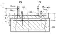
- Figure 2 is a plan view showing a schematic arrangement of a first electrode 11A connected to a first tab lead 15A, a second electrode 11B connected to a second tab lead 15B, and a separator 13 interposed between the first electrode 11A and the second electrode 11B in stacking order.
- first electrode 11A and the second electrode 11B are shown hatched.
- first pull-out portion 15Aa of the first tab lead 15A and the second pull-out portion 15Ba of the second tab lead 15B, both having a length L are shown hatched.
- the first electrode 11A and the second electrode 11B are stacked so that most of them overlap.
- the separator 13 is placed between the first electrode 11A and the second electrode 11B so that they do not come into contact with each other.
- two first tab leads 15A are connected to the first electrode 11A
- two second tab leads 15B are connected to the second electrode 11B.
- FIG. 3 is a perspective view showing a schematic example of the wound body 10.
- a separator 13 is also disposed on the outermost periphery of the wound body 10, and the end of the winding is secured with a stop tape 14 (see Figure 2).
- connection positions of the two first tab leads 15A to the first electrode 11A and the two second tab leads 15B to the second electrode 11B are set so that the two first pull-out portions 15Aa overlap each other and the two second pull-out portions 15Ba overlap each other on the winding body 10, as shown in FIG. 3.
- Each tab lead protrudes as if planted from the end face of the winding body 10.
- the lead-out positions of the first tab leads 15A and the lead-out positions of the second tab leads 15B on the end face of the winding body 10 are arranged symmetrically with respect to the center of the winding body 10, but the lead-out positions can be changed depending on the design.
- each tab lead is parallel to the winding axis direction (arrow A) in Figures 2 and 3
- the longitudinal direction of each tab lead may be inclined with respect to the winding axis direction when connected to each electrode.
- the first tab lead 15A and the second tab lead 15B may be configured so that the hatched first pull-out portion 15Aa of the first tab lead 15A and the second pull-out portion 15Ba of the second tab lead 15B are inclined with respect to the winding axis direction.
- Step (ii) Step (ii) is a step of connecting external terminals to the tab leads (external terminal connecting step (S3)).
- a rod-shaped first external terminal 17A is connected to the first tab lead 15A
- a rod-shaped second external terminal 17B is connected to the second tab lead 15B.
- Two second tab leads 15B having the same polarity are overlapped at the connection portion and connected to the second external terminal 17B, as shown in FIG. 4.
- two first tab leads 15A having the same polarity are overlapped at the connection portion and connected to the first external terminal 17A.
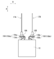
- the second external terminal 17B may include, for example, a lead body portion 171, a tip portion 172 that is inserted into the sealing member 20, and a base portion 173 that is positioned closer to the connection portion with the tab lead than the tip portion 172.
- the base portion 173 has a larger diameter than the insertion hole of the tip portion 172 provided in the sealing member 20.
- the base portion 173 makes it easier to position the second external terminal 17B relative to the sealing member 20 and makes it difficult for the second external terminal 17B to come out of the sealing member 20.
- the first external terminal 17A is connected to the first tab lead 15A in a similar manner (see FIG. 7).
- a washer 18 may be disposed on the opposite side of the base end 173.
- the second connection portion 16B (see FIG. 7) of the second tab lead 15B may then be sandwiched between the base end 173 and the washer 18.
- the first connection portion 16A of the first tab lead 15A may be sandwiched between the base end 173 and the washer 18.
- the washer 18 is used as necessary.
- Step (iii) is a step of adhering a solid electrolyte to the wound body to obtain a capacitor element (adhering a solid electrolyte (S4)).
- the wound body By applying a solid electrolyte to the wound body, at least a portion of the dielectric coating formed on the surface of the anode member is covered with the solid electrolyte.
- the solid electrolyte functions as a de facto cathode material.
- the solid electrolyte improves the capacitance of the electrolytic capacitor and reduces the interelectrode resistance between the first and second electrodes, which is advantageous for achieving a low ESR.
- the wound body with the solid electrolyte applied thereto is referred to as a capacitor element to distinguish it from the wound body.
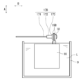
- the method of impregnating the wound body with the treatment liquid is preferably a method of immersing the wound body 10 in the treatment liquid L contained in a container 9 as shown in FIG. 5, which is simple.
- the immersion time depends on the size of the wound body 10, but is, for example, 1 second to 5 hours, and preferably 1 minute to 30 minutes.
- the impregnation is preferably performed under reduced pressure, for example, in an atmosphere of 10 to 100 kPa, and preferably 40 to 100 kPa.
- Ultrasonic vibration may be applied to the wound body 10 or the treatment liquid L while immersed in the treatment liquid.
- the process of impregnating the wound body 10 with the treatment liquid L and the process of drying the wound body 10 may be repeated two or more times. By performing these processes multiple times, the coverage rate of the solid electrolyte layer with respect to the dielectric coating can be increased.
- a capacitor element in which a solid electrolyte containing a conductive polymer is sandwiched between the first electrode 11A and the second electrode 11B.
- the solid electrolyte preferably contains a conductive polymer.
- a ⁇ -conjugated polymer may be used as the conductive polymer.
- the solid electrolyte may contain a ⁇ -conjugated polymer and a dopant.
- Examples of ⁇ -conjugated polymers that can be used include polypyrrole, polythiophene, polyfuran, polyaniline, and derivatives of these.
- Derivatives refer to polymers that have polypyrrole, polythiophene, polyfuran, polyaniline, or the like as their basic skeleton.
- polythiophene derivatives include poly(3,4-ethylenedioxythiophene) (PEDOT). These may be used alone or in combination of two or more types, or may be copolymers of two or more types of monomers.
- the weight-average molecular weight of the conductive polymer is not particularly limited, but is, for example, 1,000 to 100,000.
- the solid electrolyte contains a polymer dopant.
- polymer dopants include anions of polyvinyl sulfonic acid, polystyrene sulfonic acid, polyallylsulfonic acid, polyacrylic sulfonic acid, polymethacrylic sulfonic acid, poly(2-acrylamido-2-methylpropanesulfonic acid), polyisoprene sulfonic acid, and polyacrylic acid. These may be used alone or in combination of two or more kinds. In addition, these may be homopolymers or copolymers of two or more kinds of monomers. Of these, polystyrene sulfonic acid (PSS) is preferable.
- PSS polystyrene sulfonic acid
- the weight-average molecular weight of the polymer dopant is not particularly limited, but is preferably, for example, 1,000 to 500,000, in order to facilitate the formation of a homogeneous solid electrolyte layer.
- the treatment liquid L may be a solution in which a conductive polymer is dissolved in a solvent, or a dispersion in which a conductive polymer is dispersed in a solvent (dispersion medium).
- the concentration of the conductive polymer contained in the treatment liquid L is preferably, for example, 0.5 to 10 mass %.
- the average particle size D50 of the conductive polymer is preferably, for example, 0.01 to 0.5 ⁇ m.
- the average particle size D50 is the median diameter in the volumetric particle size distribution determined by a particle size distribution measuring device using the dynamic light scattering method.
- Treatment liquid L of such a concentration is suitable for forming a solid electrolyte layer of appropriate thickness and is easily impregnated into the dielectric layer.
- the solvent is evaporated from the conductive polymer attached to the dielectric layer by drying. This forms a solid electrolyte containing the conductive polymer so as to cover at least a portion of the dielectric layer.
- the treatment liquid L can be obtained, for example, by dispersing a conductive polymer in a solvent, or by polymerizing a precursor monomer in a solvent to generate conductive polymer particles.
- a preferred treatment liquid is, for example, poly(3,4-ethylenedioxythiophene) (PEDOT) doped with polystyrene sulfonate (PSS), i.e., PEDOT/PSS.
- the solvent may be water, a mixture of water and a non-aqueous solvent, or a non-aqueous solvent.
- the non-aqueous solvent is not particularly limited, but for example, a protic solvent or an aprotic solvent can be used.
- the solvent may contain 50 mass% or more of water.
- FIG. 6 is a perspective view showing a schematic diagram of a process for connecting an external terminal (second external terminal 17B) to a tab lead (second tab lead 15B).
- a through hole 15a is formed at one end of each tab lead.
- the lead body portion 171 of the second external terminal 17B is inserted into the through holes 15a of the two second tab leads 15B.
- the second tab lead 15B extends in the winding axis direction (arrow A), and the second external terminal 17B extends in a direction intersecting the winding axis direction (arrow B).
- the connection portion of the second tab lead 15B is pressed from both main surface sides to crush the end of the second external terminal 17B on the washer 18 side.
- the second external terminal 17B to be engaged and connected to the second tab lead 15B.
- the first external terminal 17A is engaged and connected to the first tab lead 15A.
- the first tab lead 15A extends in the winding axis direction (arrow A), and the first external terminal 17A extends in a direction intersecting the first direction (arrow B).
- Step (iv) After the solid electrolyte is applied to the wound body and the connection of each external terminal to each tab lead is completed, in step (iv), as shown in FIG. 7, each tab lead is bent toward the inner periphery of the wound body at a position where it is led out from the end face of the wound body 10 to form a first portion (S5).
- the external terminal extending in the direction of arrow B is rotated and positioned so that it extends in the winding axis direction (arrow A).
- the first tab lead 15A and the second tab lead 15B are each bent to form a first portion and a second portion.
- the first tab lead 15A is bent from a lead-out position on the end face of the winding body 10 toward the inner periphery of the winding body 10, extends in a direction approaching the center of the winding body 10 (first direction), and then bends in a direction opposite to the first direction to form a first portion 15Ax and a second portion 15Ay.
- the second tab lead 15B is bent from a lead-out position on the end face of the winding body 10 toward the inner periphery of the winding body 10, extends in a direction approaching the center of the winding body 10 (first direction), and then bends in a direction opposite to the first direction to form a first portion 15Bx and a second portion 15By.
- connection portion 16A between the first tab lead 15A and the first external terminal 17A faces the end face of the winding body 10 via the first portion 15Ax.
- connection portion 16B between the second tab lead 15B and the second external terminal 17B faces the end face of the wound body 10 via the first portion 15Bx.
- Step (v) is a step of inserting the tip of the external terminal connected to the tab lead into the insertion hole of the sealing material 20, accommodating the capacitor element in the bottomed case 60 (accommodating step (S6)), and sealing the opening of the bottomed case 60 with the sealing material 20 through which the external terminal passes (sealing step (S8)).
- the tip ends of the external terminals connected to each tab lead may be inserted into the insertion holes of the sealing member 20. This integrates the wound body 10 and the sealing member 20. If the sealing member 20 includes a rubber material, the tip ends of the external terminals may be pressed into the rubber material.
- FIG. 8 is a side view showing the wound body 10 after the external terminals have been inserted into the insertion holes of the sealing member 20. At this time, each external terminal is engaged with the sealing member 20 by the protruding end 172 of each external terminal. Each external terminal is positioned by the base end 173. In this way, the wound body 10 and the sealing member 20 are integrated.
- the wound body 10 integrated with the sealing material 20 is housed in a bottomed case 60.
- the first tab lead 15A and the second tab lead 15B are bent, but the pull-out portions 15Aa and 15Ba are short, and there is little interference between the first external terminal 17A and the second external terminal 17B.
- the wound body may be impregnated with a liquid component (liquid component impregnation step (S7)).
- the impregnation step is carried out, for example, after the wound body is housed in a bottomed case.
- the liquid component improves the self-repairing performance of the dielectric coating.
- the liquid component since the liquid component essentially functions as a cathode material, it is expected to have the effect of increasing the electrostatic capacitance. There are no particular limitations on the impregnation method.
- the wound body 10 is sealed with the bottomed case 60 and the sealing material 20. This completes the electrolytic capacitor 100.
- Figure 9 is a cross-sectional view showing a schematic example of a completed electrolytic capacitor.
- an aging process may be performed while applying the rated voltage to the electrolytic capacitor.
- the sealing member 20 When the sealing member 20 includes a rubber material, the sealing member 20 may be placed on the open end of the bottomed case 60, and the open end of the bottomed case 60 may be bent inward.
- the sealing member 20, which includes a rubber material, is crimped by the open end without being damaged. This fixes the sealing member 20 to the bottomed case 60 and seals the bottomed case 60.
- the bottomed case 60 may be recessed inward so as to compress the sealing member 20.
- an annular groove is formed on the portion of the inner surface of the bottomed case 60 that faces the sealing member 20. This reduces the diameter of the sealing member 20, which prevents the sealing member 20 from coming off even when the internal pressure increases.
- FIG. 10 shows an example of a capacitor element in the electrolytic capacitor of the second embodiment.
- the outer shape of the wound body, the tab leads, and the external terminals are shown, and the details of the wound body are omitted because they are the same as those of the first embodiment.
- the first tab lead 15A and the second tab lead 15B are not derived from positions symmetrical with respect to the center of the wound body 10A.
- the central angle formed by the derived position of the first tab lead 15A and the derived position of the second tab lead 15B, centered on the winding axis (the center of the wound body 10A), is approximately 90° to 130°.
- the first tab lead 15A protrudes (implants) so that the first lead-out portion 15Aa of the first tab lead 15A extends in a direction inclined with respect to the winding axis direction as a shape before bending at the lead-out position on the end face of the winding body 10
- the second tab lead 15B protrudes (implants) so that the second lead-out portion 15Ba of the second tab lead 15B extends in a direction inclined with respect to the winding axis direction as a shape before bending at the lead-out position on the end face of the winding body 10.
- the tab lead may be cut out so that the lead-out portion is bent in advance, an unbent tab lead may be connected to the electrode in a diagonal direction, or the lead-out portion may be folded back. With this configuration, even if the end face of the winding body 10A is small, the tab lead can be bent to form the first portion while avoiding interference between external terminals.
- the first tab lead 15A and the second tab lead 15B are each bent at a lead-out position on the end face of the winding body 10, so that the first portion 15Ax of the first tab lead 15A and the first portion 15Bx of the second tab lead 15B each extend along the end face of the winding body 10A.
- the direction in which the first portion 15Ax extends (first direction) is generally parallel to the direction in which the first portion 15Bx extends (first direction).
- the angle formed by the extension direction of the first portion 15Ax and the extension direction of the first portion 15Bx is, for example, in the range of 0° to 20° or less.
- the tab lead is bent from the exit position on the end face of the winding body 10A toward the inner circumference and not bent any further, the length of the tab lead becomes very short. The shorter the tab lead, the smaller the resistance of the tab lead, which is even more advantageous in reducing ESR.
- FIG. 11 shows an example of a capacitor element in the electrolytic capacitor of the third embodiment.
- the outer shape of the wound body, the tab leads, and the external terminals are shown, and the details of the wound body are omitted because they are the same as those of the first embodiment.
- the central angle formed by the lead-out position of the first tab lead 15A and the lead-out position of the second tab lead 15B, centered on the winding axis (the center of the wound body 10B), is approximately 90° to 130°.
- the first tab lead 15A as a shape before bending at the lead-out position on the end face of the winding body 10, has a first lead-out portion 15Aa of the first tab lead 15A protruding (implanted) so as to extend in a direction inclined with respect to the winding axis direction
- the second tab lead 15B as a shape before bending at the lead-out position on the end face of the winding body 10, has a second lead-out portion 15Ba of the second tab lead 15B protruding (implanted) so as to extend in a direction inclined with respect to the winding axis direction.
- first tab lead 15A and the second tab lead 15B By bending each of the first tab lead 15A and the second tab lead 15B at the lead-out position on the end face of the winding body 10 and then folding back in the opposite direction, a first portion 15Ax and a second portion Ay are formed in the first lead-out portion 15Aa of the first tab lead 15A, and a first portion 15Bx and a second portion 15By are formed in the second lead-out portion 15Ba of the second tab lead 15B.
- the first portion 15Ax and the first portion 15Bx extend along the end surface of the wound body 10A, and the direction in which the first portion 15Ax extends (first direction) is generally parallel to the direction in which the first portion 15Bx extends (first direction).
- the second portion 15Ay extends by bending in the opposite direction at the tip of the first portion 15Ax in the first direction
- the second portion 15By extends by bending in the opposite direction at the tip of the first portion 15Bx in the first direction, so that the folded structure of the first portion and the second portion is formed while avoiding interference between the external terminals.
- the angle between the extension direction of the first portion 15Ax and the second portion 15Ay and the extension direction of the first portion 15Bx and the second portion By is, for example, in the range of 0° to 20°.
- connection portion between the tab lead and the external terminal is formed in the second portion. Therefore, the first portion of the tab lead is interposed between the connection portion and the end face of the winding body 10B.
- the connection between the tab lead and the external terminal does not collide directly with the end face of the wound body, so the impact on the connection is reduced and the connection state between the tab lead and the external terminal is further stabilized.
- the impact on the wound body 10B is also reduced, deterioration of the wound body is suppressed, which is also advantageous for suppressing an increase in ESR.
- the connection between the external terminal and the tab lead is less susceptible to the effects of the vibration of the wound body. Therefore, the connection state between the tab lead and the external terminal is further stabilized.
- Figures 12 to 14 show an electrolytic capacitor 100 obtained by housing the wound body 10B shown in Figure 11 in a bottomed case 60 and sealing the opening of the bottomed case 60 with a sealing member 20 through which the first external terminal 17A and the second external terminal 17B pass.
- Figure 12 is a cross-sectional view in a plane parallel to the winding axis, including the first external terminal 17A and the second external terminal 17B of an electrolytic capacitor having the wound body 10B.
- Figure 13 is a cross-sectional view in a plane parallel to the winding axis, including a tab lead extending along the end face of the wound body of an electrolytic capacitor having the wound body 10B.
- Figure 14 is an external view of an example of an electrolytic capacitor 100.
- the first electrode functions as, for example, an anode member.
- the first electrode is a metal foil containing at least one valve metal such as titanium, tantalum, aluminum, and niobium.
- the first electrode may contain the valve metal in the form of an alloy containing the valve metal or a compound containing the valve metal.
- the thickness of the first electrode is not particularly limited, and is, for example, 15 ⁇ m or more and 300 ⁇ m or less. The thickness is the average value at any five points (hereinafter the same).
- the surface of the first electrode may be roughened by etching or the like.
- a dielectric coating may be formed on the surface of the first electrode.
- the dielectric coating is formed, for example, by subjecting the first electrode to a chemical conversion treatment.
- the dielectric coating may contain an oxide of a valve metal.
- the dielectric coating is not limited to this, and may be any material that functions as a dielectric.
- the second electrode functions as, for example, a cathode.
- the second electrode may be a metal foil.
- the type of metal is not particularly limited, and may be a valve metal or an alloy containing a valve metal like the first electrode, or may be a valve metal other than iron (Fe) or copper (Cu).
- the thickness of the second electrode is not particularly limited, and is, for example, 15 ⁇ m or more and 300 ⁇ m or less.
- the surface of the second electrode may be roughened or chemically treated as necessary.
- an inorganic layer containing carbon, nickel, titanium, or oxides or nitrides of these elements may be formed on the surface of the second electrode.
- the tab lead is in the form of a foil.
- the tab lead is a conductive member having a thickness of 15 ⁇ m or more and 300 ⁇ m or less.
- the material thereof is not particularly limited as long as it is conductive, and examples thereof include aluminum, titanium, nickel, copper, iron, tantalum, niobium, and alloys thereof.
- the separator is not particularly limited as long as it is porous.
- Examples of the separator include nonwoven fabric made of cellulose fiber, nonwoven fabric made of glass fiber, microporous membrane, woven fabric, nonwoven fabric, etc. made of polyolefin.
- the thickness of the separator is not particularly limited, and is, for example, 10 ⁇ m or more and 500 ⁇ m or less. When a conductive polymer or solid electrolyte with a sufficient thickness is disposed between the first electrode and the second electrode, the separator may be omitted.
- the external terminal is a member used to lead out the electrode to the outside, and has electrical conductivity.
- the external terminal may be rod-shaped and has a rigidity sufficient to allow it to be inserted into the sealing member.
- the material of the external terminal may be any material as long as it has electrical conductivity. There is no particular limitation, and examples thereof include aluminum, titanium, nickel, copper, iron, tantalum, niobium, and alloys thereof.
- the sealing member closes the opening of the bottomed case.
- the sealing member may be made of an insulating material.
- the sealing member preferably includes a rubber member.
- the rubber member has elasticity. Therefore, when the external terminal is inserted into the sealing member, damage to both the external terminal and the sealing member is easily suppressed. Furthermore, even when the internal pressure increases, the rubber member deforms, suppressing cracks in the sealing member and suppressing damage to the internal leads.
- the International Rubber Hardness Degrees (IRHD) of the rubber member is preferably 99 or less, more preferably 95 or less.
- the IRHD of the rubber member is preferably 70 or more, more preferably 80 or more.
- Examples of elastic polymers that make up such rubber members include silicone rubber, fluorine-containing rubber, ethylene propylene rubber, chlorosulfonated polyethylene rubber (such as Hypalon rubber), butyl rubber, isoprene rubber, and isobutyl-isoprene rubber. Of these, fluorine-containing rubber is preferred from the viewpoint of heat resistance.
- One type of elastic polymer may be used alone, or two or more types may be used in combination.
- the sealing member has one or more insertion holes for inserting the external terminals.
- the positions of the insertion holes are set appropriately according to the positions of the external terminals.
- the number of insertion holes is set appropriately according to the number of external terminals.
- the bottomed case has an opening.
- the bottomed case includes a cylindrical portion and a bottom surface that closes one end of the cylindrical portion.
- the other end (open end) of the cylindrical portion is closed with a sealing member.
- the outer shape of the bottomed case is, for example, cylindrical or approximately cylindrical.
- the material of the bottomed case is not particularly limited, and examples include metals such as aluminum, aluminum alloy, stainless steel, copper, iron, and brass.
- a surface layer e.g., an oxide layer, a resin layer, etc.
- having a desired function may be formed on the outer surface of the bottomed case.
- the liquid component includes a solvent.
- the solvent include a sulfone compound, a lactone compound, a carbonate compound, and a polyhydric alcohol.
- the sulfone compound include sulfolane, dimethyl sulfoxide, and diethyl sulfoxide.
- the lactone compound include ⁇ -butyrolactone and ⁇ -valerolactone.
- the carbonate compound include dimethyl carbonate (DMC), diethyl carbonate (DEC), ethyl methyl carbonate (EMC), ethylene carbonate (EC), propylene carbonate (PC), and fluoroethylene carbonate (FEC).
- the polyhydric alcohol include glycol compounds such as ethylene glycol (EG), diethylene glycol, triethylene glycol, propylene glycol, and polyethylene glycol (PEG); and glycerin. These may be used alone or in combination.
- the solvent may contain a compound having two or more hydroxyl groups.
- An example of such a compound is a polyhydric alcohol.
- the content of the compound having two or more hydroxyl groups may be 50% by mass or more, 60% by mass or more, or 70% by mass or more of the total solvent.
- the liquid component may further contain an acid component.
- an acid component When a conductive polymer and a dopant are attached to the electrolytic capacitor, the acid component in the liquid component suppresses the de-doping phenomenon of the dopant and stabilizes the conductivity of the conductive polymer. Even if the dopant is de-doped from the conductive polymer, the acid component of the liquid component is redoped at the site of the de-doping, making it easier to maintain a low ESR.
- the concentration of the acid component may be 5 mass% or more and 50 mass% or less, or 15 mass% or more and 35 mass% or less.
- the liquid component may contain a base component together with an acid component. At least a portion of the acid component is neutralized by the base component. Thus, it is possible to suppress corrosion of the electrode caused by the acid component while increasing the concentration of the acid component. From the viewpoint of effectively suppressing dedoping, it is preferable that the acid component is in excess of the base component in terms of equivalent ratio.
- the equivalent ratio of the acid component to the base component may be 1 or more and 30 or less.
- the concentration of the base component contained in the liquid component may be 0.1 mass% or more and 20 mass% or less, or 3 mass% or more and 10 mass% or less.
- the pH of the liquid component is preferably 4 or less, more preferably 3.8 or less, and even more preferably 3.6 or less. By setting the pH of the liquid component to 4 or less, deterioration of the conductive polymer is further suppressed.
- the pH is preferably 2.0 or more.
- a capacitor element; a bottomed case that accommodates the capacitor element; a sealing member that seals an opening of the bottomed case; an external terminal penetrating the sealing member; Equipped with the capacitor element comprises a wound body and a solid electrolyte attached to the wound body, the winding body includes a tab lead extending from an end face of the winding body and connected to the external terminal, The tab lead has a first portion that is bent toward the inner periphery of the winding body at a position where it is led out from the end face of the winding body and extends in a first direction.
- the tab lead further includes a second portion bent in a reverse direction at a tip of the first portion in the first direction to face the first portion,
- the capacitor element has two or more tab leads having the same polarity including the tab lead, the two or more tab leads are overlapped at the connection portion and connected to the external terminal;
- the capacitor element has two or more tab leads having the same polarity including the tab lead, the two or more tab leads are overlapped at the connection portion and connected to the external terminal;
- This disclosure can be used in electrolytic capacitors that have a solid electrolyte.
Landscapes
- Engineering & Computer Science (AREA)
- Power Engineering (AREA)
- Microelectronics & Electronic Packaging (AREA)
- Electric Double-Layer Capacitors Or The Like (AREA)
Priority Applications (2)
| Application Number | Priority Date | Filing Date | Title |
|---|---|---|---|
| JP2024574505A JPWO2024162158A1 (https=) | 2023-01-31 | 2024-01-25 | |
| CN202480009152.XA CN120530469A (zh) | 2023-01-31 | 2024-01-25 | 电解电容器及其制造方法 |
Applications Claiming Priority (2)
| Application Number | Priority Date | Filing Date | Title |
|---|---|---|---|
| JP2023013337 | 2023-01-31 | ||
| JP2023-013337 | 2023-01-31 |
Publications (1)
| Publication Number | Publication Date |
|---|---|
| WO2024162158A1 true WO2024162158A1 (ja) | 2024-08-08 |
Family
ID=92146310
Family Applications (1)
| Application Number | Title | Priority Date | Filing Date |
|---|---|---|---|
| PCT/JP2024/002146 Ceased WO2024162158A1 (ja) | 2023-01-31 | 2024-01-25 | 電解コンデンサおよびその製造方法 |
Country Status (3)
| Country | Link |
|---|---|
| JP (1) | JPWO2024162158A1 (https=) |
| CN (1) | CN120530469A (https=) |
| WO (1) | WO2024162158A1 (https=) |
Citations (8)
| Publication number | Priority date | Publication date | Assignee | Title |
|---|---|---|---|---|
| JPS5771331U (https=) * | 1980-10-16 | 1982-04-30 | ||
| JPS59180421U (ja) * | 1983-05-19 | 1984-12-01 | 信英通信工業株式会社 | 電解コンデンサ |
| JPH05259004A (ja) * | 1992-03-10 | 1993-10-08 | Matsushita Electric Ind Co Ltd | アルミ電解コンデンサ |
| JP2003297677A (ja) * | 2002-03-29 | 2003-10-17 | Nippon Chemicon Corp | 固体電解コンデンサ |
| JP2012004481A (ja) * | 2010-06-21 | 2012-01-05 | Sanyo Electric Co Ltd | 電解コンデンサ |
| JP2012074643A (ja) * | 2010-09-30 | 2012-04-12 | Hitachi Aic Inc | アルミニウム電解コンデンサ |
| JP2017022222A (ja) * | 2015-07-09 | 2017-01-26 | Necトーキン株式会社 | 固体電解コンデンサおよびその製造方法 |
| WO2021172440A1 (ja) * | 2020-02-28 | 2021-09-02 | パナソニックIpマネジメント株式会社 | 電解コンデンサおよびその製造方法 |
-
2024
- 2024-01-25 JP JP2024574505A patent/JPWO2024162158A1/ja active Pending
- 2024-01-25 WO PCT/JP2024/002146 patent/WO2024162158A1/ja not_active Ceased
- 2024-01-25 CN CN202480009152.XA patent/CN120530469A/zh active Pending
Patent Citations (8)
| Publication number | Priority date | Publication date | Assignee | Title |
|---|---|---|---|---|
| JPS5771331U (https=) * | 1980-10-16 | 1982-04-30 | ||
| JPS59180421U (ja) * | 1983-05-19 | 1984-12-01 | 信英通信工業株式会社 | 電解コンデンサ |
| JPH05259004A (ja) * | 1992-03-10 | 1993-10-08 | Matsushita Electric Ind Co Ltd | アルミ電解コンデンサ |
| JP2003297677A (ja) * | 2002-03-29 | 2003-10-17 | Nippon Chemicon Corp | 固体電解コンデンサ |
| JP2012004481A (ja) * | 2010-06-21 | 2012-01-05 | Sanyo Electric Co Ltd | 電解コンデンサ |
| JP2012074643A (ja) * | 2010-09-30 | 2012-04-12 | Hitachi Aic Inc | アルミニウム電解コンデンサ |
| JP2017022222A (ja) * | 2015-07-09 | 2017-01-26 | Necトーキン株式会社 | 固体電解コンデンサおよびその製造方法 |
| WO2021172440A1 (ja) * | 2020-02-28 | 2021-09-02 | パナソニックIpマネジメント株式会社 | 電解コンデンサおよびその製造方法 |
Also Published As
| Publication number | Publication date |
|---|---|
| CN120530469A (zh) | 2025-08-22 |
| JPWO2024162158A1 (https=) | 2024-08-08 |
Similar Documents
| Publication | Publication Date | Title |
|---|---|---|
| CN103392214B (zh) | 电解电容器及其制造方法 | |
| JP7847300B2 (ja) | 電解コンデンサ | |
| US10014118B2 (en) | Electrolytic capacitor | |
| WO2016174807A1 (ja) | 電解コンデンサ | |
| JP2009188184A (ja) | 電解コンデンサとその製造方法 | |
| WO2016189779A1 (ja) | 電解コンデンサ | |
| JPWO2017163725A1 (ja) | 電解コンデンサおよびその製造方法 | |
| JP6735510B2 (ja) | 電解コンデンサ | |
| US12308180B2 (en) | Electrolytic capacitor and method for producing same | |
| CN113994446A (zh) | 固体电解电容器和其制造方法 | |
| CN110098057A (zh) | 电解电容器的制造方法 | |
| KR100334240B1 (ko) | 전기 에너지 저장 장치 및 그 제조방법 | |
| JP6726886B2 (ja) | 電解コンデンサおよびその製造方法 | |
| WO2024162158A1 (ja) | 電解コンデンサおよびその製造方法 | |
| US20250174410A1 (en) | Electrolytic capacitor and manufacturing method therefor | |
| JP2001284174A (ja) | 固体電解コンデンサとその製造方法 | |
| WO2024062720A1 (ja) | 電解コンデンサ及びその製造方法 | |
| JP4568947B2 (ja) | 固体電解コンデンサの製造方法 | |
| JPH10335184A (ja) | 固体電解コンデンサ | |
| WO2024204627A1 (ja) | 電解コンデンサおよびその製造方法 | |
| CN114026664B (zh) | 电解电容器及其制造方法 | |
| US20250357051A1 (en) | Electrolytic capacitor and method for producing same | |
| JP2001284181A (ja) | 固体電解コンデンサ | |
| JP2001284190A (ja) | 固体電解コンデンサ | |
| JP2024151869A (ja) | 電解コンデンサ |
Legal Events
| Date | Code | Title | Description |
|---|---|---|---|
| 121 | Ep: the epo has been informed by wipo that ep was designated in this application |
Ref document number: 24750107 Country of ref document: EP Kind code of ref document: A1 |
|
| WWE | Wipo information: entry into national phase |
Ref document number: 2024574505 Country of ref document: JP |
|
| WWE | Wipo information: entry into national phase |
Ref document number: 202480009152.X Country of ref document: CN |
|
| WWP | Wipo information: published in national office |
Ref document number: 202480009152.X Country of ref document: CN |
|
| NENP | Non-entry into the national phase |
Ref country code: DE |
|
| 122 | Ep: pct application non-entry in european phase |
Ref document number: 24750107 Country of ref document: EP Kind code of ref document: A1 |