WO2024161813A1 - 医療デバイス - Google Patents
医療デバイス Download PDFInfo
- Publication number
- WO2024161813A1 WO2024161813A1 PCT/JP2023/044730 JP2023044730W WO2024161813A1 WO 2024161813 A1 WO2024161813 A1 WO 2024161813A1 JP 2023044730 W JP2023044730 W JP 2023044730W WO 2024161813 A1 WO2024161813 A1 WO 2024161813A1
- Authority
- WO
- WIPO (PCT)
- Prior art keywords
- convex portion
- convex
- straight
- tapered
- base end
- Prior art date
- Legal status (The legal status is an assumption and is not a legal conclusion. Google has not performed a legal analysis and makes no representation as to the accuracy of the status listed.)
- Ceased
Links
Images


Classifications
-
- A—HUMAN NECESSITIES
- A61—MEDICAL OR VETERINARY SCIENCE; HYGIENE
- A61M—DEVICES FOR INTRODUCING MEDIA INTO, OR ONTO, THE BODY; DEVICES FOR TRANSDUCING BODY MEDIA OR FOR TAKING MEDIA FROM THE BODY; DEVICES FOR PRODUCING OR ENDING SLEEP OR STUPOR
- A61M29/00—Dilators with or without means for introducing media, e.g. remedies
-
- A—HUMAN NECESSITIES
- A61—MEDICAL OR VETERINARY SCIENCE; HYGIENE
- A61B—DIAGNOSIS; SURGERY; IDENTIFICATION
- A61B17/00—Surgical instruments, devices or methods
- A61B17/34—Trocars; Puncturing needles
-
- A—HUMAN NECESSITIES
- A61—MEDICAL OR VETERINARY SCIENCE; HYGIENE
- A61M—DEVICES FOR INTRODUCING MEDIA INTO, OR ONTO, THE BODY; DEVICES FOR TRANSDUCING BODY MEDIA OR FOR TAKING MEDIA FROM THE BODY; DEVICES FOR PRODUCING OR ENDING SLEEP OR STUPOR
- A61M25/00—Catheters; Hollow probes
- A61M25/0067—Catheters; Hollow probes characterised by the distal end, e.g. tips
- A61M25/0068—Static characteristics of the catheter tip, e.g. shape, atraumatic tip, curved tip or tip structure
Definitions
- This disclosure relates to medical devices.
- Medical devices are known for expanding holes in the walls of organs such as the stomach or liver, or narrowed areas in body cavities such as the bile duct or pancreatic duct.
- Such medical devices have a tapered section on the core shaft, and the hole is expanded by pushing this tapered section into the hole. It has been proposed to provide a helical convex section on the outer circumferential surface of this tapered section and the adjacent straight section (see, for example, Patent Document 1).
- the core shaft and the protrusions are made of a hard material (e.g., stainless steel, etc.), a sufficient expansion diameter can be obtained. For this reason, it is thought that the medical device of Patent Document 1 has reduced flexibility and would have difficulty passing through curved parts of blood vessels, etc. If the core shaft and the protrusions are made of a soft material (e.g., resin, etc.), the flexibility is improved. However, in this case, it is thought that it would be difficult to obtain a sufficient expansion diameter.
- a hard material e.g., stainless steel, etc.
- the purpose of this disclosure is to provide a medical device that is both flexible and easy to achieve a sufficient expansion diameter.
- a medical device is a medical device comprising: a core shaft having a tapered section that narrows from the base end towards the tip, and a straight section of constant outer diameter adjacent to the tapered section and extending along the longitudinal direction; and protrusions provided on the outer circumferential surfaces of the tapered section and the straight section and extending spirally along the longitudinal direction with gaps between adjacent sections, the protrusions having a first protrusion located on the tapered section and a second protrusion located on the straight section, the rigidity of the first protrusion being different from the rigidity of the second protrusion.
- a medical device is capable of obtaining a hole with a sufficient expansion diameter.
- the first convex portion may be made of a resin material
- the second convex portion may be made of a metal material.
- Such a medical device may be configured so that the rigidity of the first convex portion and the rigidity of the second convex portion are different, and for example, the rigidity of the first convex portion may be lower than the rigidity of the second convex portion.
- the first convex portion and the second convex portion may have the same cross-sectional shape.
- the frictional resistance between the first convex portion and the puncture portion and the frictional resistance between the second convex portion and the puncture portion when passing through a hole can be made equal, and the same propulsive force can be obtained in the tapered portion and the straight portion.
- the medical device can easily form a hole with a sufficient expansion diameter.
- the straight portion may be provided on the base end side of the tapered portion. Such a medical device can maintain the diameter of the expanded hole by the straight portion on the base end side.
- the straight portion may be provided at the distal end and proximal end of the tapered portion.
- the straight portion at the distal end of such a medical device makes it easier to insert the device into the hole, and the straight portion at the proximal end can maintain the diameter of the expanded hole.
- the rigidity of the first protrusion may be lower than the rigidity of the second protrusion.
- the rigidity of the first protrusion may be greater than the rigidity of the second protrusion. Such a medical device can obtain a hole with a sufficient expansion diameter.
- FIG. 2 is a schematic side view of the dilator according to the first embodiment.
- FIG. 4 is a cross-sectional view of a first protrusion.
- FIG. 4 is a cross-sectional view of a second protrusion.
- FIG. 13 is a schematic side view of a dilator according to a second embodiment.
- FIG. 13 is a schematic side view of a dilator according to a third embodiment.
- FIG. 13 is a schematic side view of a dilator according to a fourth embodiment.
- Fig. 1 is a schematic side view of a dilator 1 as a medical device according to the first embodiment.
- the tip tip 11 side is the tip side (distal side) that is inserted into the body
- the gripping portion 41 side is the base end side (hand side, proximal side) that is operated by a technician such as a doctor.
- the dilator 1 comprises a distal tip 11, a core shaft 21, a helical convex portion 31, and a gripping portion 41.
- the distal tip 11 is located at the most distal end of the dilator 1.
- the distal tip 11 is formed by pouring solder material (silver-tin solder material, gold-tin solder material, etc.) into the tip of the core shaft 21, and is approximately cylindrical in shape with an internal cavity 11a.
- the core shaft 21 is a member having a tapered portion and a straight portion.
- the tapered portion tapers from the base end to the tip.
- the straight portion is adjacent to the tapered portion and extends along the longitudinal axis, and has a constant outer diameter.
- the positional relationship (front-to-back relationship) between the tapered portion and the straight portion in the longitudinal direction is not particularly limited.
- they may be arranged in the order of tapered portion, straight portion, tapered portion, or straight portion, tapered portion, straight portion.
- the core shaft 21 in this embodiment is composed of a coil body in which one or more metal wires 21w are wound in a spiral shape around the longitudinal axis of the core shaft 21.
- the core shaft 21 has an inner cavity 21a that passes through from the base end to the tip.
- a guide wire (not shown) or the like is inserted into the inner cavity 21a.
- the core shaft 21 has, in order from the tip side, a first straight section 22, a tapered section 23, a second straight section 24, and a base end section 25.
- the first straight section 22 is connected to the base end of the tip tip 11 and extends from the base end of the tip tip 11 toward the base end side.
- the tapered section 23 is connected to the base end of the first straight section 22 and reduces in diameter from the base end toward the tip.
- the second straight section 24 is connected to the base end of the tapered section 23 and extends from the base end of the tapered section 23 toward the base end side.
- the base end section 25 is connected to the base end of the second straight section 24 and extends from the base end of the second straight section 24 toward the base end side.
- the first and second straight sections 22, 24 have a constant outer diameter.
- the wires 21w that make up the core shaft 21 are inserted into a body cavity, so they are preferably antithrombotic, flexible, and biocompatible.
- materials that can be used to make such wires include metal materials such as stainless steel and superelastic alloys such as nickel-titanium, or resin materials.
- the convex portion 31 is a portion provided on the outer peripheral surface of the tapered portion and the straight portion.
- the convex portion 31 extends in a spiral shape with a gap between adjacent portions along the longitudinal direction.
- the convex portion 31 has a first convex portion 32 located on the tapered portion 23, and second convex portions 33, 34 located on the first and second straight portions 22, 24.
- the first convex portion 32 is composed of a coil body 32C in which one or more wires 32w are wound around the outer circumferential surface of the tapered portion 23 in the opposite direction to the core shaft 21.
- Each of the second convex portions 33, 34 is composed of a coil body 33C, 34C in which one or more wires 33w, 34w are wound around the outer circumferential surfaces of the first and second straight portions 22, 24 in the opposite direction to the core shaft 21.
- the rigidity of the first convex portion 32 is different from that of the second convex portions 33 and 34.
- the rigidity of the first convex portion 32 is configured to be lower than that of the second convex portions 33 and 34.
- the first convex portion 32 is made of a resin material
- the second convex portions 33 and 34 are made of a metal material.
- the metal material of the second convex portions 33 and 34 has a larger Young's modulus than the resin material of the first convex portion 32.
- materials constituting the wire 32w of the first convex portion 32 include resin materials such as polyvinyl chloride resin, urethane resin, polyolefin resin, polyamide resin, and fluororesin.
- Examples of materials constituting the wires 33w and 34w of the second convex portions 33 and 34 include metal materials such as stainless steel and superelastic alloy materials such as nickel-titanium alloy.
- the first convex portion 32 and the second convex portions 33 and 34 have a substantially circular cross section and are the same shape.
- the cross section of the first convex portion 32 is a cross section perpendicular to the long axis extending along the first convex portion 32 and extending in a spiral shape. The same applies to the second convex portions 33 and 34.
- Methods for joining the core shaft 21 to the first convex portion 32 and the second convex portions 33 and 34 include, for example, brazing with a brazing material, bonding with an adhesive, welding, etc.
- the gripping portion 41 is the part where the operator pushes the dilator 1 into the body and rotates it.
- the tip of this gripping portion 41 is connected to the base end of the base end portion 25 of the core shaft 21, and has an inner cavity 41a that communicates with the inner cavity 21a of the core shaft 21.
- the shape of the gripping portion 41 can be formed, for example, into a shape that makes it easy for the operator to operate the dilator 1.
- the inner cavities 11a, 21a, and 41a form a lumen L. For example, a guide wire or the like is inserted into the lumen L.
- This example illustrates a procedure in which an introduction needle (not shown) is used to make a hole in the area to be treated (for example, the wall of an organ such as the stomach or liver, hereinafter also referred to as the "area to be expanded") and then this hole is expanded using a dilator 1.
- an introduction needle (not shown) is used to make a hole in the area to be treated (for example, the wall of an organ such as the stomach or liver, hereinafter also referred to as the "area to be expanded") and then this hole is expanded using a dilator 1.
- the doctor uses the introduction needle to puncture the area to be expanded and make a hole.
- the doctor inserts a guidewire into the lumen of the introduction needle and then removes the introduction needle.
- the doctor then inserts the base end of the guidewire into the lumen L of the dilator 1 and inserts the dilator 1 into the body.
- the doctor passes the guidewire through a bent portion of a blood vessel or the like without rotating the core shaft 21, and delivers the tip of the dilator 1 to just before the portion to be enlarged.
- the doctor inserts the tip 11 into the hole of the portion to be enlarged, and operates the gripping portion 41 to rotate the core shaft 21 and push the dilator 1 forward, enlarging the hole of the portion to be enlarged.
- the tapered portion 23 advances due to the screw action of the spiral first convex portion 32 caused by the rotation of the core shaft 21, and the tapered portion 23 expands the hole.
- the rigidity of the first convex portion 32 is configured to be lower than the rigidity of the second convex portions 33 and 34, so that the necessary flexibility can be obtained when passing through a bent portion.
- the second convex portions 33 and 34 have a higher rigidity than the first convex portion 32, so that a sufficient expansion diameter of the hole can be obtained. In this way, with the dilator 1 of this embodiment, it is possible to achieve both flexibility when passing through a bent portion and the ease of obtaining a sufficient expansion diameter of the hole.
- Fig. 4 is a schematic side view of a dilator 101 according to the second embodiment.
- the tip tip 11 side is the tip side (distal side) that is inserted into the body
- the gripping portion 41 side is the base end side (hand side, proximal side) that is operated by a technician such as a doctor.
- the dilator 101 of this embodiment has a basically same structure as the dilator 1 of the first embodiment, so the same members are given the same numbers and detailed description is omitted.
- the dilator 101 comprises a distal tip 11, a core shaft 121, a helical convex portion 131, and a grip portion 41.
- the core shaft 121 is a member having a tapered portion and a straight portion.
- the tapered portion reduces in diameter from the base end to the tip.
- the straight portion is adjacent to the tapered portion, extends along the longitudinal direction, and has a constant outer diameter. The straight portion is provided only on the base end side of the tapered portion.
- the core shaft 121 of this embodiment is composed of a coil body in which one or more metal wires 121w are wound in a spiral shape around the long axis of the core shaft 121.
- the core shaft 121 has an inner cavity 121a that penetrates from the base end to the tip.
- a guide wire (not shown) or the like is inserted into the inner cavity 121a.
- the inner cavities 11a, 121a, and 41a form a lumen L.
- the core shaft 121 has, in order from the tip side, a tapered section 23, a straight section 24, and a base end section 25.
- the tip tip 11 is connected to the tip of the tapered section 23.
- the convex portion 131 is a portion provided on the outer peripheral surface of the tapered portion and the straight portion.
- the convex portion 131 extends in a spiral shape with a gap between adjacent portions along the longitudinal axis.
- the convex portion 131 has a first convex portion 32 located on the tapered portion 23 and a second convex portion 34 located on the straight portion 24.
- the dilator 101 of this embodiment is able to achieve both flexibility when passing through bent sections and ease of achieving a sufficient expansion diameter for the hole.
- Fig. 5 is a schematic side view of a dilator 201 according to the third embodiment.
- the tip tip 11 side is the tip side (distal side) that is inserted into the body
- the gripping portion 41 side is the base end side (hand side, proximal side) that is operated by a technician such as a doctor.
- the same members as those of the dilator 1 of the first embodiment are given the same numbers, and detailed descriptions are omitted.
- the dilator 201 comprises a distal tip 11, a core shaft 221, a helical convex portion 31, and a grip portion 41.
- the core shaft 221 is a member having a tapered portion and a straight portion. The tapered portion reduces in diameter from the base end to the tip. The straight portion is adjacent to the tapered portion and extends along the longitudinal direction, and has a constant outer diameter.
- the core shaft 221 of this embodiment is composed of an integrally formed hollow shaft.
- the core shaft 221 has an inner cavity 221a that penetrates from the base end to the tip.
- the inner cavity 11a, the inner cavity 221a, and the inner cavity 41a form a lumen L.
- the core shaft 221 has, in order from the tip side, a first straight portion 222, a tapered portion 223, a second straight portion 224, and a base end portion 225.
- the first straight portion 222 is connected to the base end of the distal tip 11 and extends from the base end of the distal tip 11 toward the base end side.
- the tapered portion 223 is connected to the base end of the first straight portion 222 and tapers in diameter from the base end toward the distal end.
- the second straight portion 224 is connected to the base end of the tapered portion 223 and extends from the base end of the tapered portion 223 toward the base end side.
- the base end portion 225 is connected to the base end of the second straight portion 224 and extends from the base end of the second straight portion 224 toward the base end side.
- the first and second straight portions 222, 224 have a constant outer diameter.
- the material that constitutes the core shaft 221 is preferably antithrombotic, flexible, and biocompatible, since it is inserted into a body cavity.
- resin materials such as polyamide resin, polyolefin resin, polyester resin, polyurethane resin, silicone resin, and fluororesin; and metal materials such as stainless steel and superelastic alloys (nickel-titanium alloys).
- the convex portion 31 is provided on the outer peripheral surface of the tapered portion and the straight portion.
- the convex portion 31 has a first convex portion 32 located on the tapered portion 223, and second convex portions 33 and 34 located on the first and second straight portions 222 and 224.
- Methods for joining the core shaft 221 to the first convex portion 32 and the second convex portions 33 and 34 include, for example, brazing with a brazing material, bonding with an adhesive, welding, etc.
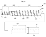
- Fig. 6 is a schematic side view of a dilator 301 according to the fourth embodiment.
- the tip tip 11 side is the tip side (distal side) that is inserted into the body
- the gripping portion 41 side is the base end side (hand side, proximal side) that is operated by a technician such as a doctor.
- the same members as those in the dilator 201 of the third embodiment are given the same numbers, and detailed descriptions are omitted.
- the dilator 301 includes a distal tip 11, a core shaft 221, a spiral convex portion 331, and a gripping portion 41.
- the convex portion 331 is a portion provided on the outer peripheral surface of the tapered portion or the tapered portion and the straight portion.
- the convex portion 331 has a gap between adjacent portions along the long axis direction.
- the convex portion 331 can be configured, for example, as a single or multiple protrusion portion that protrudes radially outward from the outer peripheral surface of the tapered portion or the straight portion and is continuous or discontinuous in the long axis direction.
- the convex portion 331 and the core shaft 221 are integrally formed.
- the convex portion 331 has a first convex portion 332 located in the tapered portion 223 and second convex portions 333, 334 located in the first and second straight portions 222, 224.
- the materials constituting the core shaft 221 and the convex portion 331 include metal materials such as stainless steel and superelastic alloy (nickel-titanium alloy).
- the convex portion 331 is integrally molded with the core shaft 221 by casting or the like.
- the rigidity of the first convex portion 332 is different from the rigidity of the second convex portions 333 and 334. By subjecting the first convex portion 332 to heat treatment or the like, the rigidity of the first convex portion 332 is configured to be lower than the rigidity of the second convex portions 333 and 334.
- the dilator 301 of this embodiment is able to achieve both flexibility when passing through bent sections and ease of achieving a sufficient expansion diameter for the hole.
- the core shaft 221 does not need to have the first straight portion 222.
- the tapered portion 223 is connected to the base end of the distal tip 11.
- the material constituting the first convex portion 32 is a resin material
- the material constituting the second convex portions 33, 34 is a metal material.
- the material constituting the first convex portion 32 and the material constituting the second convex portions 33, 34 may be a resin material or a metal material.
- the rigidity of the first convex portions 32, 332 is configured to be lower than the rigidity of the second convex portions 33, 34, 333, 334.
- the rigidity of the first convex portions 32, 332 may be configured to be higher than the rigidity of the second convex portions 33, 34, 333, 334.
- a dilator having such a configuration can obtain a sufficient expansion diameter.
Landscapes
- Health & Medical Sciences (AREA)
- Life Sciences & Earth Sciences (AREA)
- General Health & Medical Sciences (AREA)
- Public Health (AREA)
- Heart & Thoracic Surgery (AREA)
- Veterinary Medicine (AREA)
- Biomedical Technology (AREA)
- Animal Behavior & Ethology (AREA)
- Engineering & Computer Science (AREA)
- Anesthesiology (AREA)
- Hematology (AREA)
- Surgery (AREA)
- Pathology (AREA)
- Nuclear Medicine, Radiotherapy & Molecular Imaging (AREA)
- Medical Informatics (AREA)
- Molecular Biology (AREA)
- Media Introduction/Drainage Providing Device (AREA)
Priority Applications (3)
| Application Number | Priority Date | Filing Date | Title |
|---|---|---|---|
| CN202380090590.9A CN120475936A (zh) | 2023-01-31 | 2023-12-13 | 医疗设备 |
| EP23919948.2A EP4659690A1 (en) | 2023-01-31 | 2023-12-13 | Medical device |
| US19/269,488 US20250339656A1 (en) | 2023-01-31 | 2025-07-15 | Medical device |
Applications Claiming Priority (2)
| Application Number | Priority Date | Filing Date | Title |
|---|---|---|---|
| JP2023012777A JP2024108422A (ja) | 2023-01-31 | 2023-01-31 | 医療デバイス |
| JP2023-012777 | 2023-01-31 |
Related Child Applications (1)
| Application Number | Title | Priority Date | Filing Date |
|---|---|---|---|
| US19/269,488 Continuation US20250339656A1 (en) | 2023-01-31 | 2025-07-15 | Medical device |
Publications (1)
| Publication Number | Publication Date |
|---|---|
| WO2024161813A1 true WO2024161813A1 (ja) | 2024-08-08 |
Family
ID=92146244
Family Applications (1)
| Application Number | Title | Priority Date | Filing Date |
|---|---|---|---|
| PCT/JP2023/044730 Ceased WO2024161813A1 (ja) | 2023-01-31 | 2023-12-13 | 医療デバイス |
Country Status (5)
| Country | Link |
|---|---|
| US (1) | US20250339656A1 (https=) |
| EP (1) | EP4659690A1 (https=) |
| JP (1) | JP2024108422A (https=) |
| CN (1) | CN120475936A (https=) |
| WO (1) | WO2024161813A1 (https=) |
Citations (5)
| Publication number | Priority date | Publication date | Assignee | Title |
|---|---|---|---|---|
| JP2014524807A (ja) | 2011-07-27 | 2014-09-25 | オリンパス エンド テクノロジー アメリカ インコーポレイテッド | 回転前進式カテーテル挿入システム |
| WO2019224970A1 (ja) * | 2018-05-24 | 2019-11-28 | 朝日インテック株式会社 | ダイレータ |
| JP2019205932A (ja) * | 2017-03-24 | 2019-12-05 | 朝日インテック株式会社 | ダイレータ |
| WO2021199763A1 (ja) * | 2020-04-03 | 2021-10-07 | 朝日インテック株式会社 | ダイレータ |
| WO2021246054A1 (ja) * | 2020-06-01 | 2021-12-09 | 朝日インテック株式会社 | ダイレータ |
-
2023
- 2023-01-31 JP JP2023012777A patent/JP2024108422A/ja active Pending
- 2023-12-13 WO PCT/JP2023/044730 patent/WO2024161813A1/ja not_active Ceased
- 2023-12-13 CN CN202380090590.9A patent/CN120475936A/zh active Pending
- 2023-12-13 EP EP23919948.2A patent/EP4659690A1/en active Pending
-
2025
- 2025-07-15 US US19/269,488 patent/US20250339656A1/en active Pending
Patent Citations (7)
| Publication number | Priority date | Publication date | Assignee | Title |
|---|---|---|---|---|
| JP2014524807A (ja) | 2011-07-27 | 2014-09-25 | オリンパス エンド テクノロジー アメリカ インコーポレイテッド | 回転前進式カテーテル挿入システム |
| JP2019205932A (ja) * | 2017-03-24 | 2019-12-05 | 朝日インテック株式会社 | ダイレータ |
| JP2020006210A (ja) * | 2017-03-24 | 2020-01-16 | 朝日インテック株式会社 | ダイレータ |
| WO2019224970A1 (ja) * | 2018-05-24 | 2019-11-28 | 朝日インテック株式会社 | ダイレータ |
| JP6997306B2 (ja) * | 2018-05-24 | 2022-01-17 | 朝日インテック株式会社 | ダイレータ |
| WO2021199763A1 (ja) * | 2020-04-03 | 2021-10-07 | 朝日インテック株式会社 | ダイレータ |
| WO2021246054A1 (ja) * | 2020-06-01 | 2021-12-09 | 朝日インテック株式会社 | ダイレータ |
Non-Patent Citations (1)
| Title |
|---|
| See also references of EP4659690A1 |
Also Published As
| Publication number | Publication date |
|---|---|
| US20250339656A1 (en) | 2025-11-06 |
| CN120475936A (zh) | 2025-08-12 |
| EP4659690A1 (en) | 2025-12-10 |
| JP2024108422A (ja) | 2024-08-13 |
Similar Documents
| Publication | Publication Date | Title |
|---|---|---|
| JP7339355B2 (ja) | 医療用管状体 | |
| JP7431001B2 (ja) | ダイレータ | |
| JP7036914B2 (ja) | ダイレータ | |
| JP4330683B2 (ja) | 管腔内挿入具及びその製造方法 | |
| JP2004024625A (ja) | カテーテルおよび医療用チューブ | |
| JPH08257128A (ja) | 医療用チューブ | |
| CN108697434B (zh) | 医疗器械 | |
| WO2020059121A1 (ja) | ダイレータ | |
| JP7457579B2 (ja) | ダイレータ | |
| JP7330129B2 (ja) | ダイレータ | |
| CN112714634B (zh) | 扩张器 | |
| JP2010057770A (ja) | カテーテル組立体 | |
| EP0473790B1 (en) | Wire for opening obstructed part of blood vessel | |
| JP7626634B2 (ja) | 高周波処置具 | |
| WO2024161813A1 (ja) | 医療デバイス | |
| JP5618421B2 (ja) | バルーンカテーテル | |
| JP2022093946A (ja) | カテーテル | |
| JPWO2015141392A1 (ja) | カテーテル及びカテーテルセット | |
| JP6769905B2 (ja) | 医療用長尺体 | |
| JP2024104068A (ja) | 医療デバイス | |
| JP2024126330A (ja) | 医療デバイス | |
| JP2024163528A (ja) | 医療デバイス | |
| JP2016174828A (ja) | 医療器具 | |
| JP2002315836A (ja) | ガイドワイヤ導入補助具およびそれを備えたカテーテル | |
| JP2019129891A (ja) | 医療用長尺体 |
Legal Events
| Date | Code | Title | Description |
|---|---|---|---|
| 121 | Ep: the epo has been informed by wipo that ep was designated in this application |
Ref document number: 23919948 Country of ref document: EP Kind code of ref document: A1 |
|
| WWE | Wipo information: entry into national phase |
Ref document number: 202380090590.9 Country of ref document: CN |
|
| WWP | Wipo information: published in national office |
Ref document number: 202380090590.9 Country of ref document: CN |
|
| NENP | Non-entry into the national phase |
Ref country code: DE |
|
| WWP | Wipo information: published in national office |
Ref document number: 2023919948 Country of ref document: EP |