WO2024157582A1 - ガイドワイヤ - Google Patents
ガイドワイヤ Download PDFInfo
- Publication number
- WO2024157582A1 WO2024157582A1 PCT/JP2023/041097 JP2023041097W WO2024157582A1 WO 2024157582 A1 WO2024157582 A1 WO 2024157582A1 JP 2023041097 W JP2023041097 W JP 2023041097W WO 2024157582 A1 WO2024157582 A1 WO 2024157582A1
- Authority
- WO
- WIPO (PCT)
- Prior art keywords
- outer layer
- guidewire
- recess
- core shaft
- recesses
- Prior art date
- Legal status (The legal status is an assumption and is not a legal conclusion. Google has not performed a legal analysis and makes no representation as to the accuracy of the status listed.)
- Ceased
Links
Images


Classifications
-
- A—HUMAN NECESSITIES
- A61—MEDICAL OR VETERINARY SCIENCE; HYGIENE
- A61M—DEVICES FOR INTRODUCING MEDIA INTO, OR ONTO, THE BODY; DEVICES FOR TRANSDUCING BODY MEDIA OR FOR TAKING MEDIA FROM THE BODY; DEVICES FOR PRODUCING OR ENDING SLEEP OR STUPOR
- A61M25/00—Catheters; Hollow probes
- A61M25/01—Introducing, guiding, advancing, emplacing or holding catheters
- A61M25/09—Guide wires
Definitions
- the present invention relates to a guidewire.
- Patent Document 1 describes a guidewire with a metal core and a coating material.
- Patent Document 2 describes a guidewire with a spiral groove at the tip.
- Guidewires need to be flexible enough to navigate curved blood vessels, but they also need to be strong enough to resist bending damage (bending strength).
- the purpose of the present invention is to improve the flexibility and bending strength of guidewires.
- the present invention has been made to solve at least some of the problems described above, and can be realized in the following form.
- One embodiment of the present invention is a guidewire having a core shaft, the core shaft having a core wire and an outer layer covering the outer periphery of the core wire, and a recess formed at the tip of the core shaft that is recessed radially inward of the core shaft.
- the guidewire has an outer layer, and the outer layer is further provided with a recess, which improves the flexibility and bending strength of the guidewire.
- the recess may penetrate the outer layer.
- the recesses penetrate the outer layer, which further improves the flexibility of the guidewire.
- a plurality of recesses may be formed in the tip of the core shaft, and the ratio of the recesses to the outer periphery of the tip of the core shaft when viewed from a first direction along the radial direction of the core shaft may be different from the ratio of the recesses to the outer periphery of the core shaft when viewed from a second direction perpendicular to the first direction and along the radial direction of the core shaft.
- the ratio of the recess to the outer circumference of the core shaft when viewed from a first direction is different from the ratio of the recess to the outer circumference of the core shaft when viewed from a second direction, making it possible to set the direction in which the core shaft is most likely to bend.
- the core shaft may include a straight portion having a substantially constant outer diameter in the axial direction, and a tapered portion provided on the base end side of the straight portion and having an outer diameter that decreases toward the tip end side of the core shaft, and a recess may be formed in the straight portion.
- the straight section is provided with a recess, which can further improve the flexibility of the tip of the guidewire.
- the core shaft may have a straight portion and a tapered portion having a recess.
- the tapered portion has a recess, which can further improve the flexibility of the tip of the guidewire.
- the present invention can be realized in various forms, such as a guidewire manufacturing method, a catheter, a catheter manufacturing method, an endoscope, a dilator, etc.
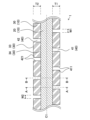
- FIG. 1 is an explanatory diagram illustrating a longitudinal cross section of an overall configuration of a guidewire according to a first embodiment
- FIG. 2 is an explanatory diagram illustrating a perspective view of a core wire and an outer layer.
- FIG. 2 is an explanatory diagram illustrating a longitudinal section of a core wire and an outer layer.
- FIG. 4 is an explanatory diagram illustrating a cross section taken along line AA in FIG. 3;
- FIG. 4 is an explanatory diagram illustrating a cross section taken along the line BB in FIG. 3;
- FIG. 3 is an explanatory diagram of a core shaft observed from a first direction in FIG. 2 .
- FIG. 3 is an explanatory diagram of the core shaft observed from a second direction in FIG. 2 .
- FIG. 13 is an explanatory diagram illustrating a cross section of a core wire and an outer layer of a guide wire according to a second embodiment.
- FIG. 13 is an explanatory diagram illustrating a cross section of a core wire and an outer layer of a guidewire according to a third embodiment.
- FIG. 13 is an explanatory diagram illustrating a longitudinal cross section of a distal end portion of a guidewire according to a fourth embodiment.
- FIG. 13 is an explanatory diagram illustrating a vertical cross section of a distal end portion of a guidewire according to a fifth embodiment.
- FIG. 13 is an explanatory diagram illustrating a core wire and an outer layer of a guide wire according to a sixth embodiment.
- FIG. 1 is an explanatory diagram illustrating a longitudinal section of the overall configuration of the guidewire 1 of the first embodiment.
- the guidewire 1 will be described with reference to FIGS. 1 to 7.
- the sizes of the components of the guidewire 1 shown in FIGS. 1 to 7 are illustrative and may be expressed on a scale different from the actual size.
- the end portion of each component of the guidewire 1 located on the tip side will be referred to as the "tip”, and the portion including the "tip” and extending from the tip to the middle toward the rear end will be referred to as the "tip portion”.
- the end portion of each component located on the rear end side will be referred to as the "rear end", and the portion including the "rear end” and extending from the rear end to the middle toward the tip side will be referred to as the "rear portion”.
- the guidewire 1 is a medical device that is inserted into blood vessels or the digestive tract and is primarily used to insert other medical devices, such as catheters, into the body.
- the guidewire 1 includes a core shaft 10, a coil 50, a fixing portion 61, and a fixing portion 62.
- the core shaft 10 includes a core wire 20 and an outer layer 30.
- the outer layer 30 includes a recess 40 that is recessed toward the radial inside of the core wire 20.
- the core wire 20 is a wire extending in the longitudinal direction of the guide wire 1.
- the core wire 20 is provided inside the outer layer 30 and extends from the tip to the rear end of the outer layer 30.
- the material of the core wire 20 is not particularly limited, but examples of the material that can be used include stainless steel (SUS302, SUS304, SUS316, etc.), superelastic alloys such as Ni-Ti alloys, piano wire, nickel-chromium alloys, cobalt alloys, platinum, gold, tungsten, tantalum, etc. It is preferable to use tantalum as the material of the core wire 20.
- the outer layer 30 is a cylindrical member that covers the outer circumference of the core wire 20.
- the outer diameter of the outer layer 30 gradually decreases from the rear end side of the outer layer 30 toward the tip side.
- the outer layer 30 has a straight portion 31 at the tip side, whose outer diameter is approximately constant in the axial direction of the outer layer 30.
- the outer layer 30 has a tapered portion 32 at the rear end side of the straight portion 31, whose outer diameter decreases toward the tip side of the outer layer 30.
- the rear end of the straight portion 31 and the tip of the tapered portion 32 are connected.
- the straight portion 31 and the tapered portion 32 cover the outer circumference of the tip of the core wire 20.
- the straight portion 31 has a recess 40 that is recessed toward the radial inside of the outer layer 30.
- the recess 40 has a groove shape that extends along the circumferential direction of the outer layer 30, and multiple recesses 40 are formed in a row at approximately equal intervals along the longitudinal direction of the outer layer 30.
- the recesses 40 are formed side by side on one side (first region S1) and the other side (second region S2) in the circumferential direction of the outer periphery 33 of the outer layer 30.
- the recesses 40 arranged at approximately equal intervals on one side in the circumferential direction of the outer periphery 33 of the outer layer 30 are also called “recesses 41", and the recesses 40 arranged at approximately equal intervals on the other side are also called “recesses 42".
- the bending strength of the core shaft 10 is improved by the outer layer 30, while the flexibility is improved by providing the recesses 40 in the outer layer 30. Details of the recesses 40 will be described later.
- the material of the outer layer 30 is not particularly limited, but examples of the material that can be used include stainless steel (SUS302, SUS304, SUS316, etc.), superelastic alloys such as Ni-Ti alloys, piano wire, nickel-chromium alloys, cobalt alloys, platinum, gold, tungsten, tantalum, etc. It is preferable to use stainless steel as the material of the outer layer 30.
- stainless steel SUS302, SUS304, SUS316, etc.
- superelastic alloys such as Ni-Ti alloys, piano wire, nickel-chromium alloys, cobalt alloys, platinum, gold, tungsten, tantalum, etc. It is preferable to use stainless steel as the material of the outer layer 30.
- the recess 40 can be formed by irradiating the outer periphery 33 of the outer layer 30 with a laser while rotating a member having the core wire 20 disposed inside the outer layer 30 around the long axis of the member.
- the melting point of the core wire 20 is higher than the melting point of the outer layer 30.
- the core shaft 10 may also be formed as a so-called clad material in which the core wire 20 and the outer layer 30 are joined by rolling or the like.
- the coil 50 is a member formed of wire wound in a spiral shape along the longitudinal direction of the core shaft 10.
- the coil 50 covers a portion of the tip side of the outer periphery 33 of the outer layer 30.
- the tip of the coil 50 is connected to the core wire 20 and the tip of the outer layer 30 by a fixing part 61.
- the rear end of the coil 50 is connected to the outer periphery 33 of the outer layer 30 by a fixing part 62.
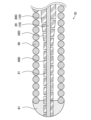
- FIG. 2 is an explanatory diagram illustrating a perspective view of the core wire 20 and the outer layer 30.
- a plurality of recesses 40 are formed along the longitudinal direction of the outer layer 30, and each recess 40 is formed along the circumferential direction of the outer periphery 33 of the outer layer 30.
- the outer periphery 33 of the outer layer 30 is divided into four regions in the circumferential direction (first region S1, second region S2, third region S3, and fourth region S4).
- the regions S1 to S4 are arranged in the circumferential direction of the outer periphery 33 and extend in the longitudinal direction of the outer layer 30.
- the regions S1 to S4 are arranged in the circumferential direction of the outer periphery 33 in the order of the first region S1, the third region S3, the second region S2, and the fourth region S4.
- the first region S1 and the second region S2 are not in contact with each other, but are in contact with the third region S3 and the fourth region S4, respectively.
- the third region S3 and the fourth region S4 are not in contact with each other, but are in contact with the first region S1 and the second region S2, respectively.
- the recesses 41 are formed in the first region S1 in a plurality of rows parallel to each other at approximately equal intervals along the longitudinal direction of the outer layer 30.
- Each recess 41 is formed from the first region S1 to the third region S3 and the fourth region S4, and both ends 410 are located in the third region S3 and the fourth region S4, respectively.
- the recesses 42 are formed in the second region S2 in a plurality of rows parallel to each other at approximately equal intervals along the longitudinal direction of the outer layer 30.
- Each recess 42 is formed from the second region S2 to the third region S3 and the fourth region S4, and both ends 420 are located in the third region S3 and the fourth region S4, respectively.
- the recesses 41 and 42 are alternately formed along the longitudinal direction of the core shaft 10 in the third region S3 and the fourth region S4.
- the recesses 42 are formed between adjacent recesses 41 in the longitudinal direction of the outer layer 30.
- the core shaft 10 constituting the third region S3 and the fourth region S4 has a larger proportion of the recesses 40 and a smaller volume of the outer layer 30 than the core shaft 10 constituting the first region S1 and the second region S2.
- the tip of the core shaft 10 is easily bent in the direction in which the third region S3 and the fourth region S4 are located.
- the volume of the outer layer 30 included in the first region S1 and the second region S2 is larger than the volume of the outer layer 30 included in the third region S3 and the fourth region S4, so the tensile strength of the core shaft 10 in the longitudinal direction can be improved.
- the distance between adjacent recesses 41 (the shortest distance in the longitudinal direction of the outer layer 30) is called “distance L1", and in the second region S2, the distance between adjacent recesses 42 is called “distance L2".
- the recesses 41 are formed so as to be parallel to each other at equal intervals in the longitudinal direction of the outer layer 30. That is, the distance L1 between adjacent recesses 41 is approximately the same.
- the recesses 42 are formed so as to be parallel to each other at equal intervals in the longitudinal direction of the outer layer 30. That is, the distance L2 between adjacent recesses 42 is approximately the same.
- the distance between adjacent recesses 41 and recesses 42 is called “distance L3".
- the adjacent recesses 41 and recesses 42 are formed so as to be equally spaced. That is, the distance L3 between each adjacent recess 41 and recess 42 is approximately the same.
- first direction V1 The direction in which the first region S1 is viewed from the front and which is aligned with the radial direction of the core shaft 10 of the outer layer 30 is referred to as the "first direction V1", and the direction in which the third region S1 is viewed from the front and which is aligned with the radial direction of the core shaft 10 and perpendicular to the first direction V1 is referred to as the "second direction V2".
- Figure 6 shows an explanatory diagram of the core shaft 10 observed from the first direction V1
- Figure 7 shows an explanatory diagram of the core shaft 10 observed from the second direction V2. Figures 6 and 7 will be described later.
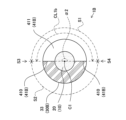
- FIG 3 is an explanatory diagram illustrating a longitudinal section of the core wire 20 and the outer layer 30.
- the recesses (41, 42) are slits that penetrate the outer layer 30.
- the side wall of the recess 41 that extends between the outer circumference 33 and the inner circumference 34 of the outer layer 30 is called the "side wall 411”
- the side wall of the recess 42 that extends between the outer circumference 33 and the inner circumference 34 of the outer layer 30 is called the "side wall 421”.
- the side walls (411, 421) are formed approximately perpendicular to the axis C1 of the core wire 20.
- the distance of the recess 41 in the radial direction of the outer layer 30 is called the "depth T1", and the distance of the recess 42 in the radial direction of the outer layer 30 is called the “depth T2".
- the depth T1 of the recess 41 and the depth T2 of the recess 42 are approximately the same as the thickness of the outer layer 30.
- the length of the recess 41 in the longitudinal direction of the outer layer 30 is referred to as "width W1," and the length of the recess 42 in the longitudinal direction of the outer layer 30 is referred to as "width W2.”
- the width W1 of the recess 41 is smaller than the depth T1, and the width W2 of the recess 42 is smaller than the depth T2.
- FIG. 4 is an explanatory diagram illustrating the A-A cross section of FIG. 3.
- the length of the recess 41 in the circumferential direction of the outer layer 30 is called the "circumferential length CL1.”
- the circumferential length CL1 of the recess 41 is greater than half the circumferential length of the outer periphery 33 of the outer layer 30.
- the angle ⁇ between the line connecting one end 410 of the recess 41 and the axis C1 of the core wire 20 and the line connecting the other end 410 of the recess 41 and the axis C1 of the core wire 20 is 180° ⁇ 360°.
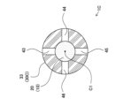
- FIG. 5 is an explanatory diagram illustrating the cross section B-B of FIG. 3.
- the length of the recess 42 in the circumferential direction of the outer layer 30 is called the "circumferential length CL2."
- the circumferential length CL2 of the recess 42 is greater than half the circumferential length of the outer periphery of the outer layer 30.
- the angle ⁇ between the line connecting one end 420 of the recess 42 and the axis C1 of the core wire 20 and the line connecting the other end 420 of the recess 42 and the axis C1 of the core wire 20 is 180° ⁇ 360°.
- the circumferential length CL1 of the recess 41 (FIG. 4) and the circumferential length CL2 of the recess 42 (FIG. 5) are greater than half the circumferential length of the outer periphery 33 of the outer layer 30. This forms the third region S3 and the fourth region S4 in which both the recess 41 and the recess 42 are provided, as described above.
- Fig. 6 is an explanatory diagram of the core shaft 10 observed from the first direction V1 in Fig. 2.
- the core wire 20 Fig. 1
- the recesses 40 41, 42
- the outer periphery 33 of the outer layer 30 are observed, but the core wire 20 is omitted in Fig. 6.
- the apparent area of the recesses 40 41, 42
- the projected area of the outer periphery 33 of the outer layer 30 in the first direction V1 is called "area Ac1”.
- Fig. 6 a part of the area As1 of the recesses 41 and a part of the area Ac1 of the outer layer 30 are shown.
- the apparent area of the outer periphery of the core shaft 10 observed from the first direction V1 is the sum (As1t+Ac1t) of the sum "As1t” of the areas As1 of the recesses 40 (41, 42) and the sum "Ac1t” of the projected areas Ac1 of the outer layer 30.
- Fig. 7 is an explanatory diagram of the core shaft 10 observed from the second direction V2 in Fig. 2.
- the core wire 20 (Fig. 1), the recesses 40 (41, 42), and the outer periphery 33 of the outer layer 30 are observed, but the core wire 20 is omitted in Fig. 7.
- the apparent area of the recesses 40 (41, 42) is called "area As2”
- the projected area of the outer periphery 33 of the outer layer 30 is called "area Ac2”.
- Fig. 7 a part of the area As2 of the recesses 40 (41, 42) and a part of the area Ac2 of the outer layer 30 are shown.
- the apparent area of the outer periphery of the core shaft 10 observed from the second direction V2 is the sum (As2t+Ac2t) of the sum "As2t” of the areas As2 of the recesses 40 (41, 42) and the sum "Ac2t” of the projected areas Ac2 of the outer layer 30.
- the ratio R1 and the ratio R2 are different. In other words, R1 ⁇ R2. Specifically, the ratio R2 is greater than the ratio R1. This makes it easier for the tip of the core shaft 10 to bend in the second direction V2.
- the bending strength of the core shaft 10 can be improved by covering the outer periphery of the core wire 20 with the outer layer 30. Furthermore, by providing a recess 40 in the outer layer 30, the flexibility of the core shaft 10 can be improved while maintaining bending strength. As a result, a guidewire 1 with good flexibility and bending strength at the tip can be provided.
- the guidewire 1 has good flexibility and can easily advance through curved blood vessels, and furthermore, has good bending strength, which reduces the possibility of the guidewire 1 being damaged by bending fracture even when inserted into a curved blood vessel.
- the recess 40 penetrates the outer layer 30. This allows the flexibility of the core shaft 10 to be further improved.
- the recess 40 is provided in the straight portion 31. This allows the flexibility of the tip side of the guidewire 1 to be further improved.
- Second Embodiment 8 is an explanatory diagram illustrating a cross section of the core wire 20 and the outer layer 30B of the guidewire 1B of the second embodiment.
- the guidewire 1B is different from the guidewire 1 of the first embodiment in the circumferential length CL1b of the recess 41B. Description of the configuration of the guidewire 1B common to the guidewire 1 will be omitted.
- the circumferential length CL1b of the recess 41B is approximately equal to half the circumferential length of the outer periphery 33 of the outer layer 30B. That is, the angle ⁇ 2 between the line connecting one end 410 of the recess 41B and the axis C1 of the core wire 20 and the line connecting the other end 410 of the recess 41B and the axis C1 of the core wire 20 is ⁇ 2 ⁇ 180°.
- the circumferential length of the recess 42B is also approximately equal to half the circumferential length of the outer periphery 33 of the outer layer 30B.
- the angle ⁇ between the line connecting one end 420 of the recess 42B and the axis C1 of the core wire 20 and the line connecting the other end 420 of the recess 42B and the axis C1 of the core wire 20 is ⁇ ⁇ 180°.
- the regions (third region S3 and fourth region S4) in which both the recesses 41B and 42B are provided are linear along the longitudinal direction of the core shaft 10.
- the guide wire 1B can also be provided with a guide wire 1B having good flexibility and bending strength at the tip.
- the angles ⁇ 2 and ⁇ may be 0° ⁇ 180° and 0° ⁇ 180°.
- the core shaft 10 can be configured such that the ease of bending differs when the tip of the core shaft 10 is bent in the first direction V1 and when it is bent in the second direction V2.
- Third Embodiment 9 is an explanatory diagram illustrating a cross section of the core wire 20 and the outer layer 30C of the guidewire 1C of the third embodiment.
- the guidewire 1C is different from the guidewire 1 of the first embodiment in that the recesses (43, 44, 45, 46) are linearly provided along the longitudinal direction of the outer layer 30C. Description of the configuration of the guidewire 1C common to the guidewire 1 will be omitted.
- the outer layer 30C has four recesses (43, 44, 45, 46). Each recess (43, 44, 45, 46) is linearly arranged along the longitudinal direction of the outer layer 30C. In the cross section of the outer layer 30C, the recesses 43 and 45 are arranged at positions opposite each other by 180 degrees with respect to the axis C1 of the core wire 20, and the recesses 44 and 46 are arranged at positions opposite each other by 180 degrees with respect to the axis C1 of the core wire 20.
- the guidewire 1C also has good flexibility and bending strength at the tip.
- Fourth Embodiment 10 is an explanatory diagram illustrating a vertical cross section of a distal end portion of a guidewire 1D of the fourth embodiment.
- the guidewire 1D differs from the guidewire 1 of the first embodiment in that a recess 40D is provided in a tapered portion 32D of an outer layer 30D. A description of parts of the configuration of the guidewire 1D that are common to the guidewire 1 will be omitted.
- the recesses 40D are provided in the straight portion 31 and the tapered portion 32D. This improves the flexibility of the tip of the guidewire 1D, including the tapered portion 32D. It is also possible to provide a guidewire 1D with good flexibility and bending strength at the tip.
- Fifth Embodiment 11 is an explanatory diagram illustrating a vertical cross section of a distal end portion of a guidewire 1E of the fifth embodiment.
- the guidewire 1E differs from the guidewire 1 of the first embodiment in that the number of recesses (41E, 42E) provided on the distal end side of the straight portion 31E is greater than the number of recesses (41E, 42E) provided on the rear end side of the straight portion 31E. Descriptions of parts of the configuration of the guidewire 1E that are common to the guidewire 1 will be omitted.
- the recesses (41E, 42E) are provided in the straight portion 31E of the outer layer 30E, and are formed so that the number of recesses (41E, 42E) increases from the rear end side of the straight portion 31E toward the tip side.
- the distance L1e of the recesses 41E provided on the tip side of the straight portion 31E is smaller than the distance L1e of the recesses 41E provided on the rear end side of the straight portion 31E.
- the distance L2e of the recesses 42E provided on the tip side of the straight portion 31E is smaller than the distance L2e of the recesses 42E provided on the rear end side of the straight portion 31E.
- the distance L3e between the recesses 41E and 42E adjacent to each other on the tip side of the straight portion 31E is smaller than the distance L3e between the recesses 41E and 42E adjacent to each other on the rear end side of the straight portion 31E. Since the recesses (41E, 42E) are provided more toward the tip side of the straight portion 31E, the volume of the tip side of the straight portion 31E is smaller than the volume of the rear end side of the straight portion 31E. This allows the guidewire 1E to have a more flexible tip. The guidewire 1E also has good flexibility and bending strength at the tip.
- the distances L1e, L2e, and L3e do not have to be constant in the longitudinal direction of the outer layer 30.
- the distance L1e of the recess 41E provided on the rear end side of the straight portion 31E may be smaller than the distance L1e of the recess 41E provided on the tip side of the straight portion 31E.
- Sixth Embodiment 12 is an explanatory diagram illustrating the core wire 20 and the outer layer 30F of the guidewire 1F of the sixth embodiment.
- the guidewire 1F is different from the guidewire 1 of the first embodiment in that the recesses (41F, 42F) do not penetrate the outer layer 30F.
- a description of the configuration of the guidewire 1F common to the guidewire 1 will be omitted.
- the recesses 41F and 42F do not penetrate the outer layer 30F.
- the depth T1f of the recess 41 and the depth T2f of the recess 42 are smaller than the thickness of the outer layer 30F.
- the guidewire 1F can also have good flexibility and bending strength at the tip.
- the outer diameter of the core wire 20 is approximately constant along the longitudinal direction of the core wire 20.
- the outer diameter of the core wire 20 does not have to be approximately constant along the longitudinal direction of the core wire 20, and for example, the outer diameter of the core wire 20 may increase from the tip side toward the rear end side of the core wire 20.
- the outer periphery of the core wire 20 is covered with the outer layer (30, 30B, 30C, 30D, 30E, 30F), but a part of the core wire 20 may not be covered with the outer layer (30, 30B, 30C, 30D, 30E, 30F).
- the outer periphery of the rear end of the core wire 20 may not be covered with the outer layer (30, 30B, 30C, 30D, 30E, 30F).
- the guidewires (1, 1B, 1C, 1D, 1E, 1F) of the first to sixth embodiments may have a thin resin film covering the outer periphery of the outer layer (30, 30B, 30C, 30D, 30E, 30F).
Landscapes
- Health & Medical Sciences (AREA)
- Life Sciences & Earth Sciences (AREA)
- Biophysics (AREA)
- Pulmonology (AREA)
- Engineering & Computer Science (AREA)
- Anesthesiology (AREA)
- Biomedical Technology (AREA)
- Heart & Thoracic Surgery (AREA)
- Hematology (AREA)
- Animal Behavior & Ethology (AREA)
- General Health & Medical Sciences (AREA)
- Public Health (AREA)
- Veterinary Medicine (AREA)
- Media Introduction/Drainage Providing Device (AREA)
Applications Claiming Priority (2)
| Application Number | Priority Date | Filing Date | Title |
|---|---|---|---|
| JP2023-009278 | 2023-01-25 | ||
| JP2023009278A JP2024104874A (ja) | 2023-01-25 | 2023-01-25 | ガイドワイヤ |
Publications (1)
| Publication Number | Publication Date |
|---|---|
| WO2024157582A1 true WO2024157582A1 (ja) | 2024-08-02 |
Family
ID=91970339
Family Applications (1)
| Application Number | Title | Priority Date | Filing Date |
|---|---|---|---|
| PCT/JP2023/041097 Ceased WO2024157582A1 (ja) | 2023-01-25 | 2023-11-15 | ガイドワイヤ |
Country Status (2)
| Country | Link |
|---|---|
| JP (1) | JP2024104874A (https=) |
| WO (1) | WO2024157582A1 (https=) |
Citations (8)
| Publication number | Priority date | Publication date | Assignee | Title |
|---|---|---|---|---|
| JP2003517893A (ja) * | 1999-12-22 | 2003-06-03 | プリシジョン・ヴァスキュラー・システムズ・インコーポレーテッド | トルク式ガイド部材システム |
| JP2005533594A (ja) * | 2002-07-25 | 2005-11-10 | ボストン サイエンティフィック リミテッド | 人体構造内を進行する医療用具及びその製造方法 |
| WO2011096531A1 (ja) * | 2010-02-05 | 2011-08-11 | テルモ株式会社 | ガイドワイヤ |
| JP2013202120A (ja) * | 2012-03-27 | 2013-10-07 | Asahi Intecc Co Ltd | ガイドワイヤ |
| JP2015536226A (ja) * | 2012-12-06 | 2015-12-21 | インディアン ウェルズ メディカル インコーポレイテッドIndian Wells Medical,Inc. | 操縦可能ガイドワイヤおよび使用方法 |
| WO2016047364A1 (ja) * | 2014-09-26 | 2016-03-31 | テルモ株式会社 | ガイドワイヤ |
| JP2016221141A (ja) * | 2015-06-03 | 2016-12-28 | 株式会社ハイレックスコーポレーション | ガイドワイヤ |
| JP2022530067A (ja) * | 2019-04-24 | 2022-06-27 | エコール・ポリテクニーク・フェデラル・ドゥ・ローザンヌ (ウ・ペ・エフ・エル) | 強化されたトルク操縦可能なガイドワイヤ |
-
2023
- 2023-01-25 JP JP2023009278A patent/JP2024104874A/ja active Pending
- 2023-11-15 WO PCT/JP2023/041097 patent/WO2024157582A1/ja not_active Ceased
Patent Citations (8)
| Publication number | Priority date | Publication date | Assignee | Title |
|---|---|---|---|---|
| JP2003517893A (ja) * | 1999-12-22 | 2003-06-03 | プリシジョン・ヴァスキュラー・システムズ・インコーポレーテッド | トルク式ガイド部材システム |
| JP2005533594A (ja) * | 2002-07-25 | 2005-11-10 | ボストン サイエンティフィック リミテッド | 人体構造内を進行する医療用具及びその製造方法 |
| WO2011096531A1 (ja) * | 2010-02-05 | 2011-08-11 | テルモ株式会社 | ガイドワイヤ |
| JP2013202120A (ja) * | 2012-03-27 | 2013-10-07 | Asahi Intecc Co Ltd | ガイドワイヤ |
| JP2015536226A (ja) * | 2012-12-06 | 2015-12-21 | インディアン ウェルズ メディカル インコーポレイテッドIndian Wells Medical,Inc. | 操縦可能ガイドワイヤおよび使用方法 |
| WO2016047364A1 (ja) * | 2014-09-26 | 2016-03-31 | テルモ株式会社 | ガイドワイヤ |
| JP2016221141A (ja) * | 2015-06-03 | 2016-12-28 | 株式会社ハイレックスコーポレーション | ガイドワイヤ |
| JP2022530067A (ja) * | 2019-04-24 | 2022-06-27 | エコール・ポリテクニーク・フェデラル・ドゥ・ローザンヌ (ウ・ペ・エフ・エル) | 強化されたトルク操縦可能なガイドワイヤ |
Also Published As
| Publication number | Publication date |
|---|---|
| JP2024104874A (ja) | 2024-08-06 |
Similar Documents
| Publication | Publication Date | Title |
|---|---|---|
| US11819647B2 (en) | Dilator | |
| JP5273820B2 (ja) | ガイドワイヤ | |
| US8608670B2 (en) | Guidewire | |
| US10493240B2 (en) | Steerable catheter handle | |
| US8951210B2 (en) | Medical guidewire | |
| US20210308423A1 (en) | Support structure for medical apparatus and method of manufacturing same | |
| US20160001048A1 (en) | Guidewire | |
| EP2689795A1 (en) | Guidewire | |
| WO2019215827A1 (ja) | 医療用チューブ | |
| JP5313613B2 (ja) | カテーテル | |
| US20130018307A1 (en) | Multi-Lumen Steerable Catheter | |
| JPH08173547A (ja) | 医療用ガイドワイヤ | |
| KR20250170114A (ko) | 연성 팁을 포함하는 혈관 내 장치 | |
| JP7137396B2 (ja) | ガイドワイヤ | |
| WO2024157582A1 (ja) | ガイドワイヤ | |
| JP2015083086A (ja) | コイル体及びガイドワイヤ | |
| WO2022158418A1 (ja) | カテーテル | |
| WO2021112067A1 (ja) | カテーテル | |
| JP3179894U (ja) | カテーテル | |
| WO2024116319A1 (ja) | 医療デバイス、医療デバイスの製造方法 | |
| JP7260408B2 (ja) | スリットパイプ及びそれを用いたガイドワイヤ | |
| JP7545339B2 (ja) | 多層コイル | |
| WO2018083905A1 (ja) | カテーテル及びカテーテル組み立て体 | |
| JP7307205B2 (ja) | カテーテル | |
| JP2024115661A (ja) | 形状付け器具 |
Legal Events
| Date | Code | Title | Description |
|---|---|---|---|
| 121 | Ep: the epo has been informed by wipo that ep was designated in this application |
Ref document number: 23918537 Country of ref document: EP Kind code of ref document: A1 |
|
| NENP | Non-entry into the national phase |
Ref country code: DE |
|
| 122 | Ep: pct application non-entry in european phase |
Ref document number: 23918537 Country of ref document: EP Kind code of ref document: A1 |