WO2024157375A1 - モータ制御装置 - Google Patents
モータ制御装置 Download PDFInfo
- Publication number
- WO2024157375A1 WO2024157375A1 PCT/JP2023/002207 JP2023002207W WO2024157375A1 WO 2024157375 A1 WO2024157375 A1 WO 2024157375A1 JP 2023002207 W JP2023002207 W JP 2023002207W WO 2024157375 A1 WO2024157375 A1 WO 2024157375A1
- Authority
- WO
- WIPO (PCT)
- Prior art keywords
- control device
- motor control
- unit
- motor
- calibration
- Prior art date
- Legal status (The legal status is an assumption and is not a legal conclusion. Google has not performed a legal analysis and makes no representation as to the accuracy of the status listed.)
- Ceased
Links
Images








Classifications
-
- H—ELECTRICITY
- H02—GENERATION; CONVERSION OR DISTRIBUTION OF ELECTRIC POWER
- H02P—CONTROL OR REGULATION OF ELECTRIC MOTORS, ELECTRIC GENERATORS OR DYNAMO-ELECTRIC CONVERTERS; CONTROLLING TRANSFORMERS, REACTORS OR CHOKE COILS
- H02P6/00—Arrangements for controlling synchronous motors or other dynamo-electric motors using electronic commutation dependent on the rotor position; Electronic commutators therefor
- H02P6/14—Electronic commutators
- H02P6/16—Circuit arrangements for detecting position
-
- H—ELECTRICITY
- H02—GENERATION; CONVERSION OR DISTRIBUTION OF ELECTRIC POWER
- H02P—CONTROL OR REGULATION OF ELECTRIC MOTORS, ELECTRIC GENERATORS OR DYNAMO-ELECTRIC CONVERTERS; CONTROLLING TRANSFORMERS, REACTORS OR CHOKE COILS
- H02P23/00—Arrangements or methods for the control of AC motors characterised by a control method other than vector control
- H02P23/14—Estimation or adaptation of motor parameters, e.g. rotor time constant, flux, speed, current or voltage
-
- H—ELECTRICITY
- H02—GENERATION; CONVERSION OR DISTRIBUTION OF ELECTRIC POWER
- H02P—CONTROL OR REGULATION OF ELECTRIC MOTORS, ELECTRIC GENERATORS OR DYNAMO-ELECTRIC CONVERTERS; CONTROLLING TRANSFORMERS, REACTORS OR CHOKE COILS
- H02P27/00—Arrangements or methods for the control of AC motors characterised by the kind of supply voltage
- H02P27/04—Arrangements or methods for the control of AC motors characterised by the kind of supply voltage using variable-frequency supply voltage, e.g. inverter or converter supply voltage
- H02P27/06—Arrangements or methods for the control of AC motors characterised by the kind of supply voltage using variable-frequency supply voltage, e.g. inverter or converter supply voltage using DC to AC converters or inverters
- H02P27/08—Arrangements or methods for the control of AC motors characterised by the kind of supply voltage using variable-frequency supply voltage, e.g. inverter or converter supply voltage using DC to AC converters or inverters with pulse width modulation
-
- H—ELECTRICITY
- H02—GENERATION; CONVERSION OR DISTRIBUTION OF ELECTRIC POWER
- H02P—CONTROL OR REGULATION OF ELECTRIC MOTORS, ELECTRIC GENERATORS OR DYNAMO-ELECTRIC CONVERTERS; CONTROLLING TRANSFORMERS, REACTORS OR CHOKE COILS
- H02P2209/00—Indexing scheme relating to controlling arrangements characterised by the waveform of the supplied voltage or current
- H02P2209/11—Sinusoidal waveform
Definitions
- the present invention relates to a motor control device.
- Patent document 1 describes a bearing equipped with a rotation sensor that can detect absolute angles.
- Patent Document 1 makes it possible to measure the bearing in advance during its manufacture, record error correction data in a component with a correction data recording unit, and detect the absolute angle without the need for calibration work after the bearing is assembled.
- Patent document 2 also describes a motor drive device that reduces speed ripples while maintaining the reproducibility of the position information of the moving element of the motor drive device.
- ellipse parameters that indicate an ellipse that approximates a Lissajous curve are calculated based on two sinusoidal signals with different phases output from a moving element of a motor drive device.
- the two sinusoidal signals are then corrected so that the ellipse becomes a new circle, and the motor drive device is controlled based on the Lissajous figure based on the corrected two sinusoidal signals and speed information that indicates the moving speed of the moving element.
- General-purpose ADCs have temperature characteristics, and distortion of the AD value occurs over time. To address this distortion of the AD value, it is possible to use the ADC's AD value calibration function for each channel.
- Patent Document 1 and Patent Document 2 do not describe any technology that allows the AD value of a general-purpose ADC to be calibrated even while the motor is being driven.
- the object of the present invention is to realize a motor control device that can calibrate the AD value of a general-purpose ADC even while the motor is being driven, thereby improving the detection accuracy of the motor's rotational electrical angle.
- the present invention is configured as follows.
- the motor control device includes a power conversion unit that converts DC power into three-phase AC power and outputs the converted three-phase AC power to a motor, a rotation angle sensor that detects the phase of the motor, and an AD converter that converts an analog signal output from the rotation angle sensor into a digital signal.
- the motor control device includes a recording unit that records a plurality of sets of data consisting of sine wave signals and cosine wave signals at the phase of the motor included in the digital signal, a calibration necessity determination unit that determines whether the phase of the motor needs to be calibrated based on the plurality of sets of data, an elliptical approximation unit that performs elliptical approximation based on the plurality of sets of data and calculates an elliptical constant when calibration of the phase of the motor is required, a calibration unit that calibrates the sine wave signals and the cosine wave signals based on the elliptical constant, and a phase calculation unit that calculates the phase based on the sine wave signals and the cosine wave signals calibrated by the calibration unit.
- the plurality of sets of data are each assigned to a predetermined number of divided regions over one electrical angle revolution or more.
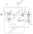
- FIG. 1 is an overall configuration diagram of a motor control device according to a first embodiment
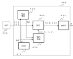
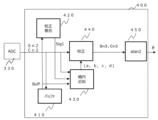
- FIG. 2 is a diagram showing an internal configuration of a rotational position detection unit 400 of the motor control device according to the first embodiment.
- FIG. 2 is an explanatory diagram of the internal configuration of an array buffer.
- FIG. 2 is an explanatory diagram of the internal configuration of an array buffer.
- FIG. 2 is an explanatory diagram of the internal configuration of an array buffer.
- FIG. 2 is an explanatory diagram of the internal configuration of an array buffer.
- FIG. 2 is an explanatory diagram of the internal configuration of an array buffer.
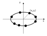
- FIG. 13 is a diagram showing an ellipse when there is no offset at the origin.
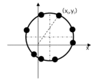
- FIG. 13 is a diagram showing a perfect circle when there is an offset at the origin.
- FIG. 13 is a diagram showing an ellipse when there is no offset at the origin.
- FIG. 13 is a diagram showing the scale of the origin distance.
- FIG. 2 is a diagram showing the internal configuration of a calibration unit.
- FIG. 11 is a diagram showing the internal configuration of a rotational position detection unit according to the second embodiment.
- FIG. 13 is a diagram showing an array configuration of stored data in an array buffer in the second embodiment.
- 13A to 13C are diagrams illustrating the operation of an ellipse approximation unit in the second embodiment.
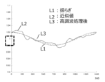
- FIG. 13 is a diagram showing a series of constants a' (waveform line).
- FIG. 13 is a diagram showing a series (wave line) of constant b'.
- FIG. 11 is a functional block diagram of an ellipse approximation unit 430 in the second embodiment.
- FIG. 2 is a diagram showing ideal sine and cosine signals for an ADC (analog-to-digital converter).
- 10 is a schematic diagram showing a sine wave signal and a cosine wave signal when the median value is fixed but the amplitudes of the sine wave signal and the cosine wave signal vary;
- FIG. FIG. 10 is a schematic diagram showing a sine wave signal and a cosine wave signal when the median value is fixed but the amplitudes of the sine wave signal and the cosine wave signal vary;
- Figure 13 shows ideal sine wave and cosine wave signals for an ADC (analog-to-digital converter). There are three potential error factors for the electrical angle when detecting the electrical angle of a motor.
- the first error factor is a conversion error caused by the temperature characteristics of the ADC.
- the ADC has an error calibration function, it cannot be used while the motor is running because it takes a long time to process.
- the second error factor is error caused by variations in the I/F (interface) performance of the ADC input circuit.
- the third error factor is error resulting from the manufacturing accuracy of the resolver.
- the first and second error factors have a fixed median but fluctuate the amplitudes of the sine wave signal and cosine wave signal, causing disturbance. This disturbance repeats for every electrical revolution. This is defined as “distortion.”
- Figure 14 is a schematic diagram showing the sine wave signal and cosine wave signal when the median is fixed but the amplitudes of the sine wave signal and cosine wave signal fluctuate. However, Figure 14 has been exaggerated for ease of understanding.
- the third error factor causes the amplitude and median to fluctuate over one mechanical angle revolution.
- the third error factor causes the median to fluctuate in addition to the amplitude fluctuation shown in Figure 14, and both occur simultaneously. This causes the entire waveform of the fluctuating amplitude to pulsate. This is defined as "fluctuation.”
- the present invention can eliminate the above distortion, suppress torque fluctuations, and stabilize control.
- a and b indicate the fluctuation in amplitude
- c and d indicate the fluctuation in the median.
- the elliptical constants (a, b, c, d) can be determined.
- the calibration process involves subtracting c from the cosine wave signal y to obtain a ⁇ cos ⁇ , and then dividing a ⁇ cos ⁇ by a to restore it to cos ⁇ . The same applies to the sine wave signal y.
- FIG. 1 is a diagram showing the configuration of a motor control device 500 according to a first embodiment of the present invention.
- the motor control device 500 shown in FIG. 1 is configured for the purpose of calibrating the distortion of the AD value caused by the temperature characteristics of the ADC 330 and calibrating the error of the I/F circuit.
- the motor control device 500 has a motor 300, a motor drive device 100, and a rotational position detection unit 400.
- the motor drive device 100 has a current control unit 110, an inverter (power converter) 130, a rotational position detection unit 400, an excitation unit 160, and an ADC 330.
- the battery 200 is the DC voltage source for the motor drive device 100.
- the DC power stored in the battery 200 is converted by the inverter 130 of the motor drive device 100 into three-phase AC power with variable voltage and variable frequency.
- the inverter 130 supplies this three-phase AC power to the motor 300.
- Motor 300 is a synchronous motor that is driven to rotate by the supply of three-phase AC power.
- a resolver 320 is attached to motor 300 as a rotation angle sensor to control the phase of the three-phase AC voltage to match the phase of the induced voltage of motor 300.
- the resolver 320 receives an excitation signal (sin ⁇ t) from the excitation unit 160 and outputs amplitude-modulated two-phase signals Sn1 and Cn1, which are 90° out of phase with each other, to the ADC (analog-to-digital converter) 330 ( ⁇ is the rotation angle of the motor).
- the ADC 330 converts the analog signal output from the resolver (rotation angle sensor) 320 into a digital signal.
- the current control unit 110 calculates the motor current values (Iu, Iv, Iw) detected by the current sensor 140 so as to follow the current command value created by the upper control device (not shown), and calculates three-phase motor voltage command values corresponding to the motor rotation angle ⁇ detected by the rotation position detection unit 150 described later.
- the current control unit 110 then creates a drive signal created by pulse width modulation (PWM) and outputs it to the inverter 130.
- PWM pulse width modulation
- the drive signal output from the current control unit 110 controls the on/off of the semiconductor switch elements that make up the main circuit in the inverter 130.
- the inverter 130 outputs three-phase voltages (Vu, Vv, Vw) to the motor 300 according to the motor voltage command value.
- the ADC 330 which is an analog-to-digital converter, detects the excitation signal (sin ⁇ t) from the two output signals (Sn1 (sin ⁇ sin ⁇ t), Cn1 (cos ⁇ sin ⁇ t)) from the resolver 320.
- the ADC 330 then outputs a pair of sine wave signal (sine wave component) Sn2 and cosine wave signal (cosine wave component) Cn2, which are digital values that are (sin ⁇ , cos ⁇ ), to the rotational position detection unit 400.
- the pair of sine wave signal Sn2 and cosine wave signal Cn2 is actually distorted as (a ⁇ sin ⁇ +c, b ⁇ cos ⁇ +d).
- the rotational position detection unit 400 calibrates the sine wave signal Sn2 and cosine wave signal Cn2 to calculate the rotational angle ⁇ of the motor.
- FIG. 2 is an internal block diagram of the rotational position detection unit 400.
- an array buffer (recording unit) 410 stores (records) a plurality of sets of data consisting of a sine wave signal Sn2 and a cosine wave signal Cn2 from the ADC 330.
- a calibration necessity determination unit 420 determines the data stored in the array buffer 410 (determines whether or not calibration of the phase of the electric motor 300 is necessary based on the plurality of sets of data) and transmits a necessity result signal Sig1 to the ellipse approximation unit 430.
- the ellipse approximation unit 430 performs ellipse approximation based on the data stored in the array buffer unit 410 and calculates a set of ellipse constants (a, b, c, d).
- the calibration unit 440 uses the set of ellipse constants (a, b, c, d) output from the ellipse approximation unit 430 to calibrate the sine wave signal Sn2 and cosine wave signal Cn2 output from the ADC 330 so that they draw a perfect circular trajectory.
- the calibration unit 440 then outputs the perfect circular sine wave signal Sn3 and cosine wave signal Cn3 to the motor rotation angle calculation unit 450.
- the motor rotation angle calculation unit 450 is indicated as atan2.
- the motor rotation angle calculation unit (phase calculation unit) 450 calculates the motor rotation angle ⁇ from the sine wave signal Sn3 and cosine wave signal Cn3 output from the calibration unit 440 (calculates the phase based on the sine wave component Sn2 and cosine wave component Cn2 calibrated by the calibration unit 440).
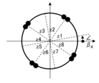
- Figures 3A to 3D and 4 are diagrams explaining the internal structure of the array buffer 410.
- pair data a minimum of four pairs of sine wave signals Sn2 and cosine wave signals Cn2 are required.
- this will be referred to as pair data.
- the motor rotation angle range of 0° to 360° is divided into eight zones and group data is collected.
- Each zone zi is designated z1, z2, ..., z8.
- Figure 3A plots the state when the sine wave signal Sn2 is the y coordinate and the cosine wave signal Cn2 is the x coordinate within zone zi. If group data is collected as shown in Figure 3A, at least four valid data can be secured even if data aggregation occurs at two locations on the x axis and two locations on the y axis, a total of four locations, as shown in Figure 3B. Therefore, it is only necessary to determine whether the data in the eight zones is sufficient, making it easy to determine whether data collection is complete. In other words, it is possible to prepare group data that is appropriately spread across the angle range of 0 to 360°.
- FIG. 3C shows an example where group data happens to be concentrated at the boundary edge between zones z1 and z2, the boundary edge between zones z3 and z4, the boundary edge between zones z5 and z6, and the boundary edge between zones z7 and z8.
- two ellipses can be assumed from these group data, so the ellipse cannot be determined.
- the elliptical approximation unit 430 extracts multiple consecutive sets of data from the sets of data spanning the mechanical angle, performs partial elliptical approximation to obtain partial elliptical constants, and slides the partial elliptical approximation to perform elliptical approximation across the entire mechanical angle, thereby obtaining the connection of the elliptical constants across the entire mechanical angle.
- Elliptical approximation can be achieved by making the boundary points of the division lines of each zone zi uneven.
- the array buffer 410 collects group data in the array buffer 410 corresponding to the determined zone zi.
- the motor rotation angle range of 0° to 360° is divided into 8 zones, but the motor rotation angle range of 0° to 360° may be equally divided into 8 or more zones (it can be divided into at least 8 regions, for example, 8 to 32 zones).
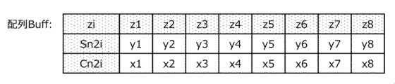
- FIG. 4 shows the data array in the array buffer 410.
- data of the sine wave signal Sn2i and the cosine wave signal Cn2i ((y1, x1) to (y8, x8)) is arrayed.
- the calibration necessity determination unit 420 uses the data ((y1, x1) to (y8, x8)) of the sine wave signal Sn2i and the cosine wave signal Cn2i to check the difference between the maximum and minimum values of the distance from the origin (origin distance) Ri, in other words, the amplitude, to determine whether calibration is necessary.
- the origin distance Ri is obtained by calculating the square root of (xi 2 + yi 2 ). Note that i is a variable, and is a number from 1 to 8 in the first embodiment.
- the calculated origin distance Ri can be stored in an appropriate memory (e.g., memory in the calibration necessity determination unit 420) as shown in FIG. 6, and the amplitude can be determined.
- an appropriate memory e.g., memory in the calibration necessity determination unit 420
- each origin distance Ri will be the radius of the circle, will be constant, there will be no difference between the maximum and minimum values, and the fluctuation will be zero.
- the existence of the major and minor axes causes the origin distance Ri to ripple twice between angles of 0° and 360°, resulting in a fluctuation between the maximum and minimum values of the origin distance Ri.
- the origin distance Ri undulates once between angles of 0 and 360°, and a fluctuation occurs between the maximum and minimum values of the origin distance Ri, as in the example shown in FIG. 5A.
- the fluctuation range of the origin distance Ri can be used to determine whether calibration is necessary.
- the calibration necessity determination unit 420 outputs the calibration necessity determination result as a necessity result signal Sig1 to the ellipse approximation unit 430.
- constants (a, b, c, d) are determined by the least squares method using a plurality of data (x k , y k ).
- Step 1 Set up an evaluation formula using the following formula (5).
- Step 2 Partially differentiate the evaluation formula for the desired parameters (A, B, C, D) using the following formula (6 (6-1 to 6-4)).
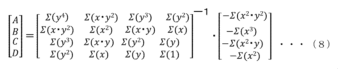
- Step 3 Create a matrix and determine the parameters as shown in the following equation (7).
- FIG. 7 is a diagram showing the internal configuration of the calibration unit 440. Distortion occurs in the sine wave signal Sn2 and the sine wave signal Cn2 output by the ADC 330. In other words, they can be expressed as distorted signals x and y, as shown in the following equations (10) and (11).
- Equations (18) and (19) show a perfect circular orbit.
- the distortion of the cosine wave and sine wave can be calibrated, and the calibration unit 440 can obtain the cosine wave signal Cn3 (cos ⁇ ) and sine wave signal Sn3 (sin ⁇ ) with calibrated distortion.
- the temperature characteristics of the ADC 330 can be cancelled, the accuracy of the detected rotation angle can be improved, and the speed ripple can be reduced.
- the first embodiment of the present invention is configured as described above, it is possible to realize a motor control device that can perform calibration of the AD value of the general-purpose ADC even while the motor is being driven, and can improve the detection accuracy of the rotational electrical angle of the motor.
- FIG. 8 is a diagram showing the internal configuration of the rotational position detection unit 400 in the second embodiment.
- the overall configuration of the motor control device 500 in the second embodiment is similar to that in the first embodiment, so illustrations and detailed explanations are omitted.
- the difference between the rotational position detection unit 400 of the second embodiment and the rotational position detection unit 40 of the first embodiment is the internal structure of the buffer 410 and the elliptical approximation 430.
- the elliptical approximation unit 430 in the second embodiment receives the sine wave signal Sn2 and the cosine wave signal Cn2.
- FIG. 9 is a diagram showing the array configuration of the stored data in the array buffer 410 in the second embodiment.
- the number of pole pairs of the rotation sensor is four.
- the ellipse approximation unit 430 distinguishes the pole pair numbers of the rotation sensor and collects group data over one mechanical revolution (collects group data over one mechanical revolution, allocating them to a specific pole pair number).
- the electrical angle of each pole pair is divided into eight zones. Since it cannot be denied that the electric motor 300 may rotate when the power supply to the motor control device 500 is off, the pole pair number when the power supply is turned on is set to 1st, and as the motor rotates forward, the pole pair number is assigned to 2nd, 3rd, 4th, and so on.
- pole pair number if x is near its maximum value and y changes from negative to positive, it is determined to be the next pole pair number. Conversely, if x is near its maximum value and y changes from positive to negative, it is determined to be the previous pole pair number.
- the sine wave signal Sn2 and cosine wave signal Cn2 overlap on the same orbit, so the pole pair number cannot be identified. However, they always cross an electrical angle of 360°E before moving on to the next pole pair number. By adding the condition of crossing 360°E, the pole pair number can be identified.
- the group data (xi, yi) is collected in the same manner as in Example 1.
- the pole pair number for each moment is defined as pole pair information Np.
- FIG. 10 shows that eight sets of data ((x3, y3) to (x10, y10)) that are continuous sets of data spanning pole pair number 1st and pole pair number 2nd are selected. These are sets of data in a 360° wide electrical angle and can be approximated by an ellipse. Although eight sets of data are selected as an example, the number is not limited to eight, and an appropriate value from 8 to 16 can be selected, for example.
- the mechanical angle information is added to the constants (a', b', c', d') calculated here. Then, the motor rotation angle calculation unit 450 calculates the electrical angle ⁇ via the calibration unit 440.
- 360° is added to the electrical angle of pole pair number 2nd
- 360° x 2 is added to the electrical angle of pole pair number 3rd
- 360° x 3 is added to the electrical angle of pole pair number 4th.
- the average value ⁇ i of each electrical angle ⁇ is first calculated, and then the electrical angle is divided by the number of pole pairs P to determine the mechanical angle ⁇ mi as the ellipse constants (a', b', c', d').
- (a'( ⁇ m1), b'( ⁇ m1), c'( ⁇ m1), d'( ⁇ m1)) is determined by (x1, y1) - (x8, y8)
- (a'( ⁇ m2), b'( ⁇ m2), c'( ⁇ m2), d'( ⁇ m2)) is determined by (x2, y2) - (x9, y9)
- (a'( ⁇ m3), b'( ⁇ m3), c'( ⁇ m3), d'( ⁇ m3)) is determined by (x3, y3) - (x10, y10).
- (a'( ⁇ m32), b'( ⁇ m32), c'( ⁇ m32), d'( ⁇ m32)) is determined by (x32, y32) - (x7, y7).
- the ellipse approximation unit 430 can also perform partial ellipse approximation and obtain a partial ellipse constant by taking the angle information of the ellipse constant as the average value of the mechanical angles used in the ellipse approximation.
- a series of constants corresponding to the mechanical angle is defined. In this way, by determining the mechanical angle at each point of the mechanical angle, the constants can be connected to generate a waveform.
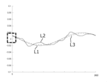
- the dotted line L2 in Figure 11A shows the series of constants a' (waveform line).
- the solid line L1 shows the series of constants a assumed at this time.
- the waveform line L3 is the waveform line shaped by applying harmonic processing to the dotted line L2.
- the waveform line L3 after harmonic processing is approximately equal to the solid line L1, which shows the fluctuations.
- FIG. 11B shows the series of constants b'.
- the solid line L1 is the constant b assumed at this time.
- constants a' and b' contain harmonics. This is because the gain and offset change while moving through a 360° electrical angle, and, for example, the start and end points do not match.
- harmonic processing can be performed.
- sine approximation sine wave approximation
- sine wave approximation can be used to process the constants in harmonic processing.
- FIG. 12 is a functional block diagram of the ellipse approximation unit 430 in the second embodiment.
- the atan processing unit (arc tangent processing unit) 431 calculates the electrical angle ⁇ from the sine wave signal Sn2 and the cosine wave signal Cn2.
- the calculated electrical angle ⁇ is output to the adder 432.
- the offset ⁇ ofst is output from the offset table 435 to the adder 432.
- the electrical angle ⁇ and the offset ⁇ ofst are added in the adder 432, and the result is supplied to the divider 433, where it is divided by the number of pole pairs p to calculate the mechanical angle ⁇ m.
- the approximation equation processor 434 executes the above equations (21) to (24), and the constants (a', b', c', d') for each moment are output to the calibration unit 440.
- the second embodiment it is possible to obtain the same effect as the first embodiment, and also to calibrate the fluctuations that occur over one mechanical revolution due to misalignment between the stator and rotor of the sensor and the inclination of the stator and rotor.
- 100...motor drive device 110...current control unit, 130...inverter, 140...current sensor, 160...excitation unit, 200...battery, 300...electric motor, 320...resolver, 330...ADC, 400...rotational position detection unit, 410...array buffer, 420...calibration necessity determination unit, 430...ellipse approximation unit, 431...a tan processing unit, 432...addition unit, 433...division unit, 434...approximation equation processing unit, 435...offset table, 440...calibration unit, 440a, 440b...multiplication and division calculator, 440c, 440d...subtractor, 450...motor rotation angle calculation unit (phase calculation unit), 500...motor control device
Landscapes
- Engineering & Computer Science (AREA)
- Power Engineering (AREA)
- Transmission And Conversion Of Sensor Element Output (AREA)
- Control Of Electric Motors In General (AREA)
Abstract
Description
図1は、本発明の実施例1であるモータ制御装置500の構成を示す図である。
モータ回転角演算部(位相演算部)450は、校正部440から出力された正弦波信号Sn3と余弦波信号Cn3とからモータ回転角θを演算する(校正部440により校正された正弦波成分Sn2及び余弦波成分Cn2に基づき位相を演算する)。
第3に、真円であるが原点がオフセットしている場合(図5Bに示す場合)、角度0~360°間で原点距離Riは、1回波打ち、図5Aに示した例と同様に、原点距離Riの最大値と最小値に振れ幅が生じる。


















次に、本発明の実施例2について説明する。
連続する電気角の360°幅ゾーンのデータを選択して楕円近似を実行し、定数(a’,b’,c’,d’)を定める。例えば、図10は、極対番号1stと極対番号2ndに跨った連続した組データである((x3,y3)~(x10,y10))の8つの組データを選択したことを示している。これらは、電気角360°幅の組データであり楕円近似可能である。選択した組データは8つの例を示すが、8つに限らず、例えば8~16のうちの適切な値を選択することができる。
b’=bb・sin(θm+β)+1 ・・・(22)
c’=cc・sin(θm+γ) ・・・(23)
d’=dd・sin(θm+η) ・・・(24)
図12は、実施例2における楕円近似部430の機能ブロック図である。
Claims (9)
- 直流電力を3相交流電力に変換し、変換した前記3相交流電力をモータへ出力する電力変換部と、
前記モータの位相を検出する回転角センサと、
前記回転角センサから出力されるアナログ信号をデジタル信号に変換するAD変換器と、を備えるモータ制御装置であって、
前記デジタル信号に含まれる前記モータの位相における正弦波信号及び余弦波信号からなる複数の組データを記録する記録部と、
前記複数の組データに基づき、前記モータの位相の校正要否を判断する校正要否判断部と、
前記モータの位相の校正が必要な場合、前記複数の組データに基づき楕円近似を行い、楕円定数を算出する楕円近似部と、
前記楕円定数に基づいて、前記正弦波信号及び前記余弦波信号を校正する校正部と、
前記校正部により校正された前記正弦波信号及び前記余弦波信号に基づき位相を演算する位相演算部と、
を有する回転位置検出部を備え、
前記複数の組データは、電気角1周分以上に渡り、所定数に分割された領域にそれぞれ振り分けられることを特徴とするモータ制御装置。 - 請求項1に記載のモータ制御装置において、
前記複数の組データは、電気角1周を少なくとも8の領域に分割されることを特徴とするモータ制御装置。 - 請求項2に記載のモータ制御装置において、
前記複数の組データは、電気角1周を少なくとも8の領域に分割するための分割線はx軸とy軸から所定角度ずらされていることを特徴とするモータ制御装置。 - 請求項3に記載のモータ制御装置において、
前記校正要否判断部は、前記複数の組データのそれぞれに対し原点との距離を求め、前記原点との距離の最大値と最小値の差が所定値を超えた場合に校正要と判断することを特徴とするモータ制御装置。 - 請求項4に記載のモータ制御装置において、
前記複数の組データは、機械角1周分に渡って、所定の極対番号にそれぞれ振り分けられ、
前記楕円近似部は、極対番号を識別し、
機械角に跨る組データから、連続する複数の組データを取り出して部分的な楕円近似を実行して部分的な楕円定数を求め、
前記の部分的な楕円近似をスライドさせて機械角全体に跨って楕円近似を実行し、
機械角全体に渡る楕円定数の繋がりを求めることを特徴とするモータ制御装置。 - 請求項5に記載のモータ制御装置において、
前記楕円近似部は、
前記余弦波信号が正値のときに、
前記正弦波信号の極性が負値から正値に変わったことをもって前記極対番号を正転側に進め、
逆に正弦波信号が正値から負値に変わったことをもって極対番号を逆転側に進め、
前記極対番号の識別を行うことを特徴とするモータ制御装置。 - 請求項5に記載のモータ制御装置において、
前記楕円近似部は、前記連続する複数の組データの取り出しの連続数を少なくとも8とすることを特徴とするモータ制御装置。 - 請求項5に記載のモータ制御装置において、
前記楕円近似部は、前記楕円定数の角度情報を楕円近似に用いた前記機械角の平均値として、前記部分的な楕円近似を実行して前記部分的な楕円定数を求めることを特徴とするモータ制御装置。 - 請求項7に記載のモータ制御装置において、
前記楕円近似部は、前記楕円定数の繋がりを正弦波近似することを特徴とするモータ制御装置。
Priority Applications (5)
| Application Number | Priority Date | Filing Date | Title |
|---|---|---|---|
| JP2024572586A JP7902974B2 (ja) | 2023-01-25 | 2023-01-25 | モータ制御装置 |
| CN202380092095.1A CN120642206A (zh) | 2023-01-25 | 2023-01-25 | 马达控制装置 |
| US19/149,908 US20260230013A1 (en) | 2023-01-25 | 2023-01-25 | Motor Control Device |
| DE112023004928.9T DE112023004928T5 (de) | 2023-01-25 | 2023-01-25 | Motorsteuerungsvorrichtung |
| PCT/JP2023/002207 WO2024157375A1 (ja) | 2023-01-25 | 2023-01-25 | モータ制御装置 |
Applications Claiming Priority (1)
| Application Number | Priority Date | Filing Date | Title |
|---|---|---|---|
| PCT/JP2023/002207 WO2024157375A1 (ja) | 2023-01-25 | 2023-01-25 | モータ制御装置 |
Publications (1)
| Publication Number | Publication Date |
|---|---|
| WO2024157375A1 true WO2024157375A1 (ja) | 2024-08-02 |
Family
ID=91970025
Family Applications (1)
| Application Number | Title | Priority Date | Filing Date |
|---|---|---|---|
| PCT/JP2023/002207 Ceased WO2024157375A1 (ja) | 2023-01-25 | 2023-01-25 | モータ制御装置 |
Country Status (5)
| Country | Link |
|---|---|
| US (1) | US20260230013A1 (ja) |
| JP (1) | JP7902974B2 (ja) |
| CN (1) | CN120642206A (ja) |
| DE (1) | DE112023004928T5 (ja) |
| WO (1) | WO2024157375A1 (ja) |
Citations (2)
| Publication number | Priority date | Publication date | Assignee | Title |
|---|---|---|---|---|
| JP2006090738A (ja) * | 2004-09-21 | 2006-04-06 | Mitsutoyo Corp | エンコーダの出力信号補正装置及び方法 |
| JP2008241345A (ja) * | 2007-03-26 | 2008-10-09 | Toshiba Mach Co Ltd | 位相検出装置及び位置検出装置 |
-
2023
- 2023-01-25 US US19/149,908 patent/US20260230013A1/en active Pending
- 2023-01-25 WO PCT/JP2023/002207 patent/WO2024157375A1/ja not_active Ceased
- 2023-01-25 DE DE112023004928.9T patent/DE112023004928T5/de active Pending
- 2023-01-25 JP JP2024572586A patent/JP7902974B2/ja active Active
- 2023-01-25 CN CN202380092095.1A patent/CN120642206A/zh active Pending
Patent Citations (2)
| Publication number | Priority date | Publication date | Assignee | Title |
|---|---|---|---|---|
| JP2006090738A (ja) * | 2004-09-21 | 2006-04-06 | Mitsutoyo Corp | エンコーダの出力信号補正装置及び方法 |
| JP2008241345A (ja) * | 2007-03-26 | 2008-10-09 | Toshiba Mach Co Ltd | 位相検出装置及び位置検出装置 |
Also Published As
| Publication number | Publication date |
|---|---|
| JPWO2024157375A1 (ja) | 2024-08-02 |
| US20260230013A1 (en) | 2026-08-06 |
| JP7902974B2 (ja) | 2026-08-10 |
| CN120642206A (zh) | 2025-09-12 |
| DE112023004928T5 (de) | 2025-12-04 |
Similar Documents
| Publication | Publication Date | Title |
|---|---|---|
| JP5148394B2 (ja) | マイクロコンピュータ,モータ制御システム | |
| JP5097858B2 (ja) | レゾルバデジタルコンバータ | |
| CN101521480A (zh) | 一种旋转变压器信号解算方法及解算器 | |
| KR20090117836A (ko) | 전력 변환 장치 | |
| US10623213B2 (en) | Method of determining a direction of rotation and valid transitions of quadrature pulses | |
| WO2004054086A1 (ja) | モータ駆動制御装置および電動パワーステアリング装置 | |
| EP4033654B1 (en) | Commutation error compensation method and apparatus for electric motor, and storage medium | |
| JP4515120B2 (ja) | レゾルバディジタル角度変換装置および方法ならびにプログラム | |
| JP5409034B2 (ja) | 回転電機制御装置 | |
| CN109188046B (zh) | 单电阻电机电流采样方法、电机驱动电路及可读存储介质 | |
| CN100511964C (zh) | 马达控制器 | |
| JP5895680B2 (ja) | 信号処理装置 | |
| KR20100118307A (ko) | 레졸버 디지털 변환장치 및 이를 이용한 위치 측정 장치 | |
| JP2013160720A (ja) | 回転角検出装置 | |
| JP5163049B2 (ja) | 交流電動機制御装置および交流電動機制御方法 | |
| JP2004333156A (ja) | エンコーダ信号内挿分割器 | |
| JPH0835857A (ja) | 回転角度検出方法 | |
| JP5092847B2 (ja) | ズレ検出装置及びズレ検出方法及び位置検出センサ付電動機の製造方法 | |
| CN119354016A (zh) | 一种单芯片旋变/lvdt信号-数字转换方法和电路 | |
| CN116184905B (zh) | 一种旋转变压器轴角软件解码方法 | |
| CN120642206A (zh) | 马达控制装置 | |
| JP7768373B2 (ja) | 電動機の制御装置 | |
| JP5912242B2 (ja) | インバータ制御装置およびインバータ制御システム | |
| KR102077362B1 (ko) | 모터제어기의 개선 | |
| JP2023124890A (ja) | モータ装置、モータ制御方法、プログラムおよび記録媒体 |
Legal Events
| Date | Code | Title | Description |
|---|---|---|---|
| 121 | Ep: the epo has been informed by wipo that ep was designated in this application |
Ref document number: 23918342 Country of ref document: EP Kind code of ref document: A1 |
|
| WWE | Wipo information: entry into national phase |
Ref document number: 2024572586 Country of ref document: JP |
|
| WWE | Wipo information: entry into national phase |
Ref document number: 202380092095.1 Country of ref document: CN |
|
| WWE | Wipo information: entry into national phase |
Ref document number: 112023004928 Country of ref document: DE |
|
| WWP | Wipo information: published in national office |
Ref document number: 202380092095.1 Country of ref document: CN |
|
| WWP | Wipo information: published in national office |
Ref document number: 112023004928 Country of ref document: DE |
|
| 122 | Ep: pct application non-entry in european phase |
Ref document number: 23918342 Country of ref document: EP Kind code of ref document: A1 |