WO2024154174A1 - 空気調和機 - Google Patents
空気調和機 Download PDFInfo
- Publication number
- WO2024154174A1 WO2024154174A1 PCT/JP2023/000911 JP2023000911W WO2024154174A1 WO 2024154174 A1 WO2024154174 A1 WO 2024154174A1 JP 2023000911 W JP2023000911 W JP 2023000911W WO 2024154174 A1 WO2024154174 A1 WO 2024154174A1
- Authority
- WO
- WIPO (PCT)
- Prior art keywords
- ventilation
- exhaust port
- exhaust
- air
- duct
- Prior art date
- Legal status (The legal status is an assumption and is not a legal conclusion. Google has not performed a legal analysis and makes no representation as to the accuracy of the status listed.)
- Ceased
Links
Images




Classifications
-
- F—MECHANICAL ENGINEERING; LIGHTING; HEATING; WEAPONS; BLASTING
- F24—HEATING; RANGES; VENTILATING
- F24F—AIR-CONDITIONING; AIR-HUMIDIFICATION; VENTILATION; USE OF AIR CURRENTS FOR SCREENING
- F24F1/00—Room units for air-conditioning, e.g. separate or self-contained units or units receiving primary air from a central station
- F24F1/0007—Indoor units, e.g. fan coil units
- F24F1/0041—Indoor units, e.g. fan coil units characterised by exhaustion of inside air from the room
Definitions
- This disclosure relates to air conditioners.
- the ventilation fan of the ventilation device In order to ensure quietness inside the room, it is preferable to place the ventilation fan of the ventilation device outside. In this case, for example, when the heater is turned on in winter, the air in the ventilation pipe connecting the room to the ventilation fan is cooled by the outside air, causing condensation to form inside the ventilation pipe. For this reason, it is preferable that the ventilation device be provided with a downward-facing drain outlet that drains the condensation water toward the ground outside.
- the ventilation device is also provided with an exhaust port for discharging air. The exhaust port is preferably directed downward to prevent rainwater from entering. If the drain outlet and exhaust port are both provided facing downward in the ventilation device, there is a risk that the water drained from the drain port will be scattered by the air blown out from the exhaust port.
- the present disclosure aims to provide an air conditioner that can suppress the splashing of water discharged from the drain outlet.
- One aspect of the air conditioner according to the present disclosure includes an indoor unit installed indoors and having a first heat exchanger, an outdoor unit installed outdoors and having a second heat exchanger, a refrigerant pipe that passes through a through hole in a wall separating the indoor and outdoor spaces and connects the first heat exchanger and the second heat exchanger, and a ventilation device that ventilates the air in the indoor space
- the ventilation device includes a ventilation pipe that passes through the through hole from the indoor space to the outdoor space and is drawn out to the outdoor space, and a ventilation device main body that is fixed to the outdoor wall surface
- the ventilation device main body includes a ventilation fan, an exhaust port that opens downward, an intake air duct that connects the ventilation pipe and the ventilation fan, an exhaust air duct that connects the ventilation fan and the exhaust port, a drain port that opens downward and drains water that accumulates in the intake air duct, and a fixed surface that faces the wall surface and extends along the wall surface, and the exhaust port is disposed farther from the fixed surface than the drain port.
- This disclosure provides an air conditioner that can suppress the splashing of water discharged from the drain outlet.
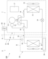
- FIG. 1 is a schematic diagram showing a schematic configuration of an air conditioner according to an embodiment.
- 1 is a schematic diagram showing an installation state of an air conditioner according to an embodiment, as viewed from the side.
- FIG. 1 is a schematic perspective view of an installation state of an air conditioner according to an embodiment.
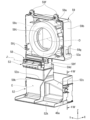
- FIG. FIG. 2 is an exploded view of the ventilation device main body according to the embodiment.
- FIG. 2 is a front view of the first member of the embodiment as viewed from the front.
- FIG. 2 is a perspective view of a fan box and a duct member according to an embodiment.
- 7 is a cross-sectional view of the duct member taken along line VII-VII in FIG. 6.
- FIG. 2 is a front view of the ventilation device main body according to the embodiment.
- FIG. 2 is a bottom view of the ventilation device main body according to the embodiment.
- 9 is a cross-sectional view of the ventilator body taken along line XX in FIG. 8.
- the drawings also show the X-axis, Y-axis, and Z-axis as appropriate.
- the X-axis shows one of the horizontal directions.
- the Y-axis shows the other of the horizontal directions.
- the Z-axis shows the vertical direction.
- the horizontal direction along the X-axis is called the "front-rear direction X”
- the horizontal direction along the Y-axis is called the "left-right direction Y”
- the vertical direction is called the "vertical direction Z”.
- the front-rear direction X, the left-right direction Y, and the vertical direction Z are mutually perpendicular directions.
- the side of the vertical direction Z toward which the Z-axis arrow points (+Z direction) is defined as the upper side
- the opposite side of the vertical direction Z to the side toward which the Z-axis arrow points (-Z direction) is defined as the lower side
- the side of the front-rear direction X toward which the X-axis arrow points (+X direction) is defined as the front
- the opposite side of the front-rear direction X to the side toward which the X-axis arrow points (-X direction) is defined as the rear.
- the side in the left-right direction Y toward which the Y-axis arrow points (+Y direction) is defined as the left
- the side opposite to the side in the left-right direction Y toward which the Y-axis arrow points (-Y direction) is defined as the right.
- Fig. 1 is a schematic diagram showing a schematic configuration of an air conditioner 100 in this embodiment.
- the air conditioner 100 includes an outdoor unit 10, an indoor unit 20, a circulation path section (refrigerant piping) 18, and a ventilation device 30.
- the outdoor unit 10 is disposed outside 7.
- the indoor unit 20 is disposed inside 8.
- the outdoor unit 10 and the indoor unit 20 are connected to each other by a circulation path section 18 through which a refrigerant 19 circulates.
- a part of the ventilation device 30 is disposed inside 8, and the other part is disposed outside 7.
- the ventilation device 30 exhausts air from the room 8 in which the indoor unit 20 is disposed to the outside 7.
- the air conditioner 100 is capable of adjusting the temperature of the air in the room 8 in which the indoor unit 20 is disposed by exchanging heat between the refrigerant 19 flowing in the circulation path section 18 and the air in the room 8 in which the indoor unit 20 is disposed.
- the refrigerant 19 include fluorine-based refrigerants or hydrocarbon-based refrigerants that have a low Global Warming Potential (GWP).
- GWP Global Warming Potential
- the outdoor unit 10 comprises an outdoor unit housing 11, a compressor 12, a heat exchanger 13, a flow control valve 14, a blower 15, a four-way valve 16, and a control unit 17.
- the outdoor unit housing 11 houses the compressor 12, the heat exchanger 13, the flow control valve 14, the blower 15, the four-way valve 16, and the control unit 17.
- the compressor 12, heat exchanger 13, flow rate control valve 14, and four-way valve 16 are provided in a portion of the circulation path 18 that is located inside the outdoor unit housing 11.
- the compressor 12, heat exchanger 13, flow rate control valve 14, and four-way valve 16 are connected by a portion of the circulation path 18 that is located inside the outdoor unit housing 11.
- the four-way valve 16 is provided in a portion of the circulation path section 18 that is connected to the discharge side of the compressor 12.
- the four-way valve 16 can reverse the direction of the refrigerant 19 flowing through the circulation path section 18 by switching a portion of the path of the circulation path section 18.
- the path connected by the four-way valve 16 is the path shown by the solid line on the four-way valve 16 in FIG. 1
- the refrigerant 19 flows through the circulation path section 18 in the direction shown by the solid arrow in FIG. 1.
- the path connected by the four-way valve 16 is the path shown by the dashed line on the four-way valve 16 in FIG. 1, the refrigerant 19 flows through the circulation path section 18 in the direction shown by the dashed arrow in FIG. 1.
- the indoor unit 20 comprises an indoor unit housing 21, a heat exchanger 22, a blower 23 as a fan, and a control unit 24.
- the indoor unit housing 21 houses the heat exchanger 22, the blower 23, and the control unit 24 inside.
- the indoor unit 20 is capable of cooling operation to cool the air in the room 8 in which the indoor unit 20 is located, and heating operation to warm the air in the room 8 in which the indoor unit 20 is located.
- the blower 23 is illustrated diagrammatically in FIG. 1.
- the refrigerant 19 flowing in the circulation path 18 flows in the direction shown by the solid arrow in Figure 1.
- the refrigerant 19 flowing in the circulation path 18 circulates through the compressor 12, the heat exchanger 13 of the outdoor unit 10, the flow control valve 14, and the heat exchanger 22 of the indoor unit 20, in that order, before returning to the compressor 12.
- the heat exchanger 13 in the outdoor unit 10 functions as a condenser
- the heat exchanger 22 in the indoor unit 20 functions as an evaporator.
- the refrigerant 19 flowing in the circulation path portion 18 flows in the direction shown by the dashed line in Figure 1.
- the refrigerant 19 flowing in the circulation path portion 18 circulates through the compressor 12, the heat exchanger 22 of the indoor unit 20, the flow control valve 14, and the heat exchanger 13 of the outdoor unit 10, in that order, before returning to the compressor 12.
- the heat exchanger 13 in the outdoor unit 10 functions as an evaporator
- the heat exchanger 22 in the indoor unit 20 functions as a condenser.
- ⁇ Indoor unit> 2 and 3 are schematic diagrams showing an installation state of the air conditioner 100 according to the embodiment.
- the indoor unit 20 is a wall-mounted indoor unit that is fixed to an upper region of a wall surface 9a of the room 8.
- the indoor unit 20 has a generally rectangular parallelepiped shape that is long in the left-right direction Y.
- the blower 23 is housed in the indoor unit housing 21.
- the blower 23 extends in the left-right direction Y.
- the blower 23 rotates around its axis of rotation by a fan motor 23a.
- the heat exchanger 22 is disposed inside the indoor unit housing 21, between the blower 23 and the indoor unit intake port 20a.
- the heat exchanger 22 extends in the left-right direction Y.
- the indoor unit housing 21 has an outer shell member 21b and an air passage member 21d.
- the outer shell member 21b is a member that constitutes part of the outer shell of the indoor unit housing 21.
- the outer shell member 21b improves the design of the appearance of the indoor unit 20.
- the outer shell member 21b is a roughly rectangular box shape that opens on the wall surface 9a side. The opening of the outer shell member 21b on the wall surface 9a side is blocked by the air passage member 21d.
- the air passage member 21d is a member that constitutes part of the air passage through which the air sucked into the indoor unit housing 21 by the blower 23 passes.
- the air passage member 21d is hooked onto an installation plate (not shown) that is fixed to the wall surface 9a on the room 8 side. This fixes the indoor unit 20 to the wall surface 9a.
- the indoor unit housing 21 has an indoor unit inlet 20a and an indoor unit outlet 20b.
- the indoor unit inlet 20a and the indoor unit outlet 20b are formed in the outer shell member 21b.
- the indoor unit inlet 20a opens upward and extends in the axial direction.
- a filter (not shown) is disposed in the indoor unit inlet 20a.
- the indoor unit outlet 20b opens toward the room 8 and extends in the axial direction.
- a wind direction control vane 25 is disposed in the indoor unit outlet 20b.
- Air from the room 8 is drawn into the indoor unit housing 21 through the indoor unit suction port 20a by the drive of the blower 23.
- the air drawn into the indoor unit housing 21 through the indoor unit suction port 20a passes through the heat exchanger 22 and is blown out into the room 8 from the indoor unit outlet 20b.
- the air passing through the indoor unit outlet 20b is blown by the air direction control vane 25 in the vertical direction Z and the left and right direction Y of the room 8.
- a control unit 24 is provided inside the indoor unit housing 21.
- the control unit 24 is disposed inside the indoor unit housing 21 at one end in the left-right direction Y.
- the control unit 24 controls the fan motor 23a, the air direction control vane 25, the heat exchanger 22, etc.
- the external shape of the indoor unit housing 21 is a rectangular column extending in the left-right direction Y.
- the indoor unit housing 21 has an upper surface 21p facing upward and a lower surface 21q facing downward.
- the indoor unit intake port 20a is provided on the upper surface 21p.
- the indoor unit exhaust port 20b is provided on the lower surface 21q.
- the indoor unit 20 is provided with a drain hose 20d.
- the tip of the drain hose 20d extends to the outside 7.
- the drain hose 20d discharges drain water that condenses on the heat exchanger 22 during cooling to the outside 7.
- the outdoor unit 10 is disposed outdoors 7.
- the outdoor unit housing 11 has an outdoor unit inlet 11b and an outdoor unit outlet 11a.
- a blower 15 sends air from the outdoor unit inlet 11b side through a heat exchanger 13 (see FIG. 1) toward the outdoor unit outlet 11a, promoting heat exchange in the heat exchanger 13.
- the outdoor unit 10 and the indoor unit 20 are connected by a circulation path section 18 and a first electrical wiring 10e.
- the circulation path section 18 is configured in a loop shape between the outdoor unit 10 and the indoor unit 20. For this reason, the circulation path section 18 connects the outdoor unit 10 and the indoor unit 20 with a pair of pipes.
- the first electrical wiring 10e includes a power supply line that supplies power to the outdoor unit 10 via the indoor unit 20, and a signal line for controlling the outdoor unit 10 and the indoor unit 20 in cooperation with each other.
- the circulation path section 18 and the first electrical wiring 10e pass through a through hole 9h provided in the wall 9 that separates the indoor space 8 from the outdoor space 7. As a result, the circulation path section 18 and the first electrical wiring 10e are drawn from the indoor space 8 to the outdoor space 7.
- the ventilation device 30 is a device that ventilates the room 8 by discharging the air inside the room 8 to the outside 7, and keeps the air inside the room 8 clean.
- the ventilation device 30 may be driven in conjunction with the indoor unit 20 and the outdoor unit 10, or may be driven independently of these.
- the ventilation device 30 has a ventilation intake section 32, a ventilation pipe 31, and a ventilation device main body 50.
- the ventilation intake section 32 is attached to the indoor unit 20 in the room 8.
- the ventilation device main body 50 is installed on the wall surface 9b of the outdoor room 7.
- the ventilation pipe 31 extends across the room 8 and the outdoor room 7.
- the ventilation intake section 32 draws in air from the room 8.
- the ventilation intake section 32 is provided on the surface of the indoor unit housing 21. In this embodiment, the ventilation intake section 32 is located on the underside 21q of the indoor unit housing 21.
- the ventilation pipe 31 is a tubular pipe.
- the ventilation pipe 31 connects the ventilation device main body 50 and the ventilation intake section 32. Therefore, one end of the ventilation pipe 31 is located inside the room 8, and the other end is located outside the room 7.
- the ventilation pipe 31 passes through the inside of the indoor unit housing 21 and the through hole 9h in the wall 9 and is drawn out to the outside the room 7.
- FIG. 4 is an exploded view of the ventilator main body 50.
- the direction perpendicular to the wall surface 9b to which the ventilation device main body 50 is attached is the front-rear direction X
- the direction perpendicular to the vertical direction Z and the front-rear direction is the left-right direction Y.
- the direction perpendicular to the wall surface 9b that moves away from the wall surface 9b is called the forward direction (+X direction)
- the direction approaching the wall surface 9b is called the rearward direction (-X direction).
- the left and right are defined based on the posture of the observer facing forward (+X direction).
- the left hand side of the observer facing the opposite side (+X direction) of the wall surface 9b is called the left side (+Y direction), and the right hand side is called the right side (-Y direction).
- the left-right direction Y of the ventilation device main body 50 and the left-right direction of the outdoor unit 10 coincide with each other, but these left-right directions Y do not necessarily have to coincide with each other.
- the ventilation device main body 50 has a base 80, a joint member 75, a backflow prevention valve 53, a ventilation fan 51, a duct member 52, and a case 40.
- the case 40 is box-shaped and opens to the rear.
- the case 40 is supported by a base 80.
- the case 40 covers the base 80 of the ventilation device main body 50, the joint member 75, the backflow prevention valve 53, the ventilation fan 51, and the duct member 52. In this way, the case 40 protects each part of the ventilation device main body 50.
- the base 80 is fixed to the wall surface 9b by fixing screws (not shown).
- the base 80 supports other components of the ventilation device main body 50.
- the ventilation pipe 31 (see FIG. 3) is connected to the base 80.
- the base 80 has a base main body 60, an installation plate 70, and a drain valve 69.
- the mounting plate 70 is a plate-shaped member made of sheet metal.
- the mounting plate 70 protects the wall surface 9b.
- the mounting plate 70 has a plate body 70a and a lower end plate portion 70c.
- the plate body 70a is arranged along the wall surface 9b.
- the plate body 70a is arranged between the base body 60 and the wall surface 9b.
- the upper end of the case 40 is engaged with the upper end of the plate body 70a.
- the plate body 70a has a fixing surface 70f facing the wall surface 9b.
- the fixing surface 70f is a flat surface.
- the mounting plate 70 is fixed to the wall surface 9b at the fixing surface 70f. In this embodiment, a case where the fixing surface 70f directly contacts the wall surface 9b will be described. However, a gap may be provided between the fixing surface 70f and the wall surface 9b by, for example, interposing a washer between the fixing surface 70f and the wall surface 9b.
- the lower end plate portion 70c is formed by bending the lower end portion of the mounting plate 70 forward.
- the lower end plate portion 70c is connected to the lower end of the plate body 70a.
- the case 40 is screwed to the lower end plate portion 70c.
- a notch portion 70d is provided in the lower end plate portion 70c. The notch portion 70d extends rearward from the front end of the lower end plate portion 70c.
- the base body 60 is fixed to the surface of the mounting plate 70 facing forward (+X direction).
- An intake air passage F is provided inside the base body 60.
- the base body 60 has a first member 61 and a second member 62 that are assembled to each other in the front-to-rear direction X.
- the intake air passage F is mainly formed between the first member 61 and the second member 62.
- the first member 61 constitutes the rear portion of the base body 60. Meanwhile, the second member 62 constitutes the front portion of the base body 60.
- the second member 62 supports the ventilation fan 51.
- the second member 62 is provided with an opening 62a that penetrates the second member 62 in the front-rear direction X.
- the downstream end of the intake air duct F opens forward at the opening 62a.
- the opening 62a is covered by the ventilation fan 51.
- FIG. 5 is a front view of the first member 61 as viewed from the front.
- the intake air passage F is formed in a U-shape when viewed from the front-rear direction X.
- the intake air passage F has an inlet portion 60p, an upstream region 60a, a turn-back region 60c, a downstream region 60b, a forward bent portion 60q, and an opening 62a.
- the inlet portion 60p is connected to the ventilation pipe 31. Air flows into the inlet portion 60p from the ventilation pipe 31.
- the upstream region 60a extends downward from the inlet portion 60p.
- the turn-back region 60c extends in the left-right direction Y.
- the turn-back region 60c connects the lower end of the upstream region 60a to the lower end of the downstream region 60b.
- the right end (-Y direction) of the turn-back region 60c is connected to the upstream region 60a.
- the left end (+Y direction) of the turn-back region 60c is connected to the downstream region 60b.
- the downstream region 60b extends upward from the folded-back region 60c.
- a forward bent portion 60q is provided at the upper end of the downstream region 60b.
- the forward bent portion 60q is bent forward (in the +X direction).
- An opening 62a is provided in front of the forward bent portion 60q. The opening 62a opens forward.
- a ventilation fan 51 (see Figure 4) is connected to the opening 62a. In this way, the intake duct F connects the ventilation pipe 31 and the ventilation fan 51.
- the base body 60 has a bottom 60d located below the intake air passage F.
- the bottom 60d forms the lower wall of the intake air passage F.
- the bottom 60d is provided with a drainage hole 61h, a valve housing portion 61k, and an induction hole 61j.
- the drain hole 61h is located below the intake air duct F.
- the drain hole 61h opens to the bottom surface 61c located below the folded region 60c of the wall surface surrounding the intake air duct F.
- the drain hole 61h extends downward from the folded region 60c to connect the folded region 60c to the valve accommodating portion 61k.
- the valve accommodating portion 61k is a space provided below the intake air duct F to accommodate the drain valve 69.
- the induction hole 61j connects the valve accommodating portion 61k to the outside of the base body.
- the drain valve 69 is disposed inside the valve housing 61k.
- the drain valve 69 faces the opening at the lower end of the drain hole 61h in the vertical direction Z.
- the drain valve 69 closes the drain hole 61h when the ventilation fan 51 is driven and negative pressure is created in the intake air duct F.
- the drain valve 69 opens the drain hole 61h when the ventilation fan 51 is stopped.
- the drain valve 69 opens the drain hole 61h due to the weight of the water, even if the ventilation fan 51 is driven.
- the ventilation pipe 31 and the ventilation device main body 50 of this embodiment are arranged outside 7.
- the ventilation device 30 When the ventilation device 30 is operated while the air conditioner 100 is heating the room, for example in winter, the heated air from the room 8 passes through the ventilation pipe 31 and the ventilation device main body 50. This air is cooled by the outside air, causing condensation to occur in the ventilation pipe 31 and the ventilation device main body 50.
- the condensed water accumulates at the lower end of the folded-back area 60c in the intake air duct F.
- the condensed water in the intake air duct F flows into the valve housing portion 61k through the drain hole 61h.
- the condensed water in the valve housing portion 61k further flows downward through the guide hole 61j and is drained from the drain outlet 46h (see FIG. 9) described later.
- the ventilation fan 51 is fixed to the base body 60 from the front (+X direction).
- the ventilation fan 51 is connected to the ventilation pipe 31 via the intake air passage F of the base body 60.
- the ventilation fan 51 may be directly connected to the ventilation pipe 31.
- the ventilation fan 51 and the ventilation pipe 31 may also be connected via another separate member.
- the ventilation fan 51 has a cylindrical rotor 51a centered on a central axis O extending in the front-rear direction X, a fan motor 51b that rotates the rotor 51a, a fan box 59 that houses the rotor 51a and the fan motor 51b, and a terminal block 51e.
- the ventilation fan 51 in this embodiment is a so-called sirocco fan.
- the ventilation fan 51 sends air from the inner diameter side to the outer diameter side of the rotor 51a by rotating the rotor 51a.
- the fan box 59 is fixed to the surface of the base body 60 facing forward (+X direction).
- a rotor 51a and a fan motor 51b are arranged inside the fan box 59.
- the fan box 59 is provided with a fan intake port 59t (see FIG. 6) that is connected to the opening 62a of the base body 60.
- the ventilation fan 51 draws air from the intake air duct F of the base body 60 at the fan intake port as the rotor 51a rotates.
- the fan box 59 also has a fan duct portion 59d that extends downward.
- the fan duct portion 59d is connected to the duct member 52 at its lower end.
- the ventilation fan 51 sends air from the fan duct portion 59d into the duct member 52.
- the terminal block 51e supports multiple terminal connections (not shown) that are connected to the fan motor 51b. These terminal connections are connected to terminals of electrical wiring (not shown) extending from the indoor unit 20 or the outdoor unit 10.
- FIG 6 is a perspective view of the fan box 59, the backflow prevention valve 53, and the duct member 52.
- the fan box 59 has a cylindrical portion 59a, a frame portion 59b, an annular plate portion 59c, and a fan duct portion 59d.
- the cylindrical portion 59a is cylindrical and centered on the central axis O of the rotor 51a (see FIG. 4).
- the cylindrical portion 59a surrounds the rotor 51a from the radial outside.
- the fan duct portion 59d is connected to the cylindrical portion 59a.
- the connection portion of the cylindrical portion 59a with the fan duct portion 59d is open in the radial direction, and the space inside the cylindrical portion 59a is connected to the air passage inside the fan duct portion 59d.
- the frame portion 59b is box-shaped and opens to the rear (-X direction).
- the frame portion 59b constitutes the outer shell of the fan box 59.
- the frame portion 59b closes the front (+X direction) opening of the cylindrical portion 59a.
- the frame portion 59b is also formed in a frame shape when viewed from the front-rear direction X, and surrounds the cylindrical portion 59a from the radial outside of the central axis O.
- the frame portion 59b is provided with a plurality of fixing portions 59f for fixing the fan box 59 to the base main body 60 (see Figure 4).
- the annular plate portion 59c is a plate extending from the rear end (-X direction) of the cylindrical portion 59a toward the inside in the radial direction of the central axis O.
- the annular plate portion 59c is provided with a circular fan intake port 59t centered on the central axis O.
- a buffer member 59g is adhesively fixed to the surface of the annular plate portion 59c facing rearward (-X direction).
- the buffer member 59g is annular and surrounds the fan intake port 59t.
- the buffer member 59g is a sponge-like member.
- the buffer member 59g is sandwiched and compressed between the fan box 59 and the base body 60. The buffer member 59g prevents air from leaking from the path that flows from the base body 60 to the fan intake port 59t.
- the fan duct portion 59d extends in the vertical direction Z.
- the fan duct portion 59d also extends in a tangential direction to the cylindrical portion 59a.
- the upper end 59j of the fan duct portion 59d is connected to the cylindrical portion 59a.
- the lower end 59k of the fan duct portion 59d opens downward.
- the swirling flow centered on the central axis O formed by the rotor 51a flows in the circumferential direction of the central axis O along the inner surface of the cylindrical portion 59a.
- the air forming the swirling flow flows into the fan duct portion 59d and flows downward inside the fan duct portion 59d.
- the expression "extending in a specific direction” means that the direction in which the object (or space) extends has a component in that specific direction over its entire length, and is not to be interpreted in a restrictive sense as being parallel to that specific direction over its entire length.
- the backflow suppression valve 53 is rotatably supported by a valve support portion 58 provided on the fan duct portion 59d.
- the backflow suppression valve 53 rotates around a rotation axis J extending in the left-right direction Y.
- the backflow suppression valve 53 has a plate body 53a arranged inside the fan duct portion 59d.
- the plate body 53a is displaced while changing the angle of the plate surface as the backflow suppression valve 53 rotates around the rotation axis J.
- the plate body 53a is arranged intersecting the extension direction of the fan duct portion 59d and blocks the air passage in the fan duct portion 59d.
- the plate body 53a When a downward air flow occurs in the air passage as the ventilation fan 51 is driven, the plate body 53a is pushed by the air and rotates downward to open the air passage. In this way, the backflow suppression valve 53 opens the air passage when the ventilation fan 51 is driven and closes the air passage when the ventilation fan 51 is stopped.
- the backflow prevention valve 53 prevents wind, rain, or insects and other living things from entering the interior of the ventilation fan 51 when the ventilation fan 51 is stopped.
- the duct member 52 is disposed below the fan duct portion 59d.
- the duct member 52 extends in the vertical direction Z.
- the duct member 52 forms an exhaust air duct E between the lower end 59k of the fan duct portion 59d and the exhaust port 46a. That is, the fan duct portion 59d is provided with an exhaust air duct E that connects the ventilation fan 51 and the exhaust port 46a.
- the exhaust air duct E extends in the vertical direction Z. The exhaust air duct E guides the air blown out from the ventilation fan 51 to the outside of the ventilation device 30.
- FIG. 7 is a cross-sectional view of the duct member 52 taken along the line VII-VII in FIG.
- the duct member as a whole extends in the vertical direction Z.
- the duct member 52 has a closure plate 52k, a first duct portion 52b, an extension portion 52c, and a second duct portion 52d that are aligned in the vertical direction Z.
- the first duct section 52b, the extension section 52c, and the second duct section 52d are arranged in series in the vertical direction Z.
- An exhaust air duct E is provided inside the first duct section 52b, the extension section 52c, and the second duct section 52d.
- the first duct section 52b opens upward and connects to the fan duct section 59d of the ventilation fan 51. Meanwhile, the second duct section 52d opens downward and connects to the exhaust port 46a.
- the extension section 52c connects between the first duct section 52b and the second duct section 52d.
- the blocking plate 52k is arranged perpendicular to the vertical direction Z. The blocking plate 52k extends rearward (in the -X direction) from the lower opening edge of the second duct section 52d.
- cross-sectional shapes of the flow paths of the first duct section 52b, the extension section 52c, and the second duct section 52d are all rectangular, but the cross-sectional lines are different from one another.
- the "cross-sectional shape of the flow path" here means a cross-section perpendicular to the air flow of the exhaust air duct E, and is a cross-section perpendicular to the vertical direction Z in the first duct section 52b, the extension section 52c, and the second duct section 52d.
- the first duct section 52b, the extension section 52c, and the second duct section 52d each have four side panels that surround the exhaust air duct E from the front-to-back direction X and the left-to-right direction Y.
- the first duct section 52b, the extension section 52c, and the second duct section 52d each have a pair of side panels that are arranged in the front-to-back direction X of the exhaust air duct E, and these side panels are arranged perpendicular to the front-to-back direction X.
- the first duct section 52b has a first left side plate 52f arranged to the left (+Y direction) of the exhaust air duct E, and a first right side plate 52e arranged to the right (-Y direction) of the exhaust air duct E.
- the extension section 52c has an extended left side plate 52h arranged to the left (+Y direction) of the exhaust air duct E, and an extended right side plate 52g arranged to the right (-Y direction) of the exhaust air duct E.
- the second duct section 52d has a second left side plate 52j arranged to the left (+Y direction) of the exhaust air duct E, and a second right side plate 52i arranged to the right (-Y direction) of the exhaust air duct E.
- the first left side plate 52f, the extended left side plate 52h, and the second left side plate 52j are perpendicular to the left-right direction Y and are arranged on approximately the same plane. In other words, the first left side plate 52f, the extended left side plate 52h, and the second left side plate 52j extend in the vertical direction Z as a single plate.
- the first right side plate 52e and the second right side plate 52i are positioned perpendicular to the left-right direction Y.
- the second right side plate 52i is positioned to the right (-Y direction) of the first right side plate 52e.
- the extended right side plate 52g connects the first right side plate 52e and the second right side plate 52i.
- the extended right side plate 52g inclines to the right (-Y direction) as it extends downward. Therefore, the extended right side plate 52g gradually moves away from the extended left side plate 52h as it extends downward.
- the extension section 52c widens the exhaust air duct E in the left-right direction Y as it moves downward.
- the cross-sectional area of the exhaust air duct E in the second duct section 52d is larger than the cross-sectional area of the exhaust air duct E in the first duct section 52b.
- the wind speed of the air flowing through the exhaust air duct E gradually slows down as it passes through the extension section 52c. For this reason, the wind speed of the air passing through the exhaust air duct E in the second duct section 52d is lower than the wind speed of the air passing through the exhaust air duct E in the first duct section 52b.
- Fig. 8 is a front view of the ventilation device main body 50.
- Fig. 9 is a bottom view of the ventilation device main body 50.
- the case 40 has a bottom plate 46.
- the bottom plate 46 covers the internal space of the case 40 from below.
- the bottom plate 46 is disposed perpendicular to the vertical direction Z.
- the bottom plate 46 is provided with an opening 46b penetrating the bottom plate 46 in the vertical direction Z.
- the opening 46b is rectangular in shape with its longitudinal direction in the left-right direction Y.
- An exhaust port 46a is disposed in an area of the opening 46b away from the wall 9. That is, the exhaust port 46a is provided in the case 40.
- the area of the opening 46b facing the wall 9 is blocked by a blocking plate 52k of the duct member 52.
- the underside of the blocking plate 52k is exposed downward from the opening 46b.
- a label, such as a warning notice, can be affixed to the underside of the blocking plate 52k.
- the exhaust port 46a opens downward.
- the exhaust port 46a is connected to an opening located at the lower end of the second duct section 52d of the duct member 52. Air flowing downward through the exhaust air duct E of the duct member 52 is exhausted from the exhaust port 46a to the outside of the ventilation device main body 50.
- the exhaust port 46a is covered by a mesh-like grill G.
- the grill G is fixed to the lower end of the second duct section 52d. The grill G prevents living organisms or foreign objects from entering the inside of the ventilation device main body 50 through the exhaust port 46a.
- the exhaust port 46a has a rectangular shape with its longitudinal direction in the left-right direction Y.
- the dimension w2 of the exhaust port 46a in the left-right direction Y is greater than the dimension w1 in the front-rear direction X.
- the exhaust port 46a is also positioned biased toward the front (front) of the bottom plate 46 of the case 40, away from the fixed surface 70f. According to this embodiment, the exhaust port 46a can be spaced away from the wall surface 9b while ensuring that the opening area of the exhaust port 46a is sufficiently wide in the left-right direction Y. This makes it possible to prevent dirt from adhering to the wall surface 9b due to the exhaust air blown out from the exhaust port 46a.
- the distance d1 between the fixing surface 70f and the exhaust port 46a is greater than the dimension w1 of the exhaust port 46a in the front-rear direction X.
- the distance d1 between the fixing surface 70f and the exhaust port 46a is greater than half the dimension d2 of the ventilation device main body 50 in the front-rear direction X.
- the distance d1 between the fixing surface 70f and the exhaust port 46a is greater than the diameter D of the ventilation piping 31.
- FIG. 10 is a cross-sectional view of the ventilator body 50 taken along line XX in FIG. 10, the base body 60 is disposed along the fixed surface 70f. Therefore, the intake airflow duct F in the base body 60 also extends along the fixed surface 70f. On the other hand, the exhaust airflow duct E extends in the vertical direction Z along the fixed surface 70f, but is disposed farther away from the fixed surface 70f than the intake airflow duct F. The intake airflow duct F and the exhaust airflow duct E overlap when viewed from the front-rear direction X.
- the intake air duct F is disposed between the exhaust air duct E and the fixed surface 70f in the front-rear direction X. This makes it easier to align the ventilation pipe 31 connected to the intake air duct F along the wall surface 9b, and allows the exhaust air duct E to be disposed away from the wall surface 9b, and the exhaust port 46a connected to the exhaust air duct E can be moved away from the wall surface 9b.
- the bottom plate 46 of the case 40 has a pair of screw holes 46c aligned in the left-right direction Y.
- the pair of screw holes 46c penetrate the bottom plate 46 in the vertical direction Z.
- the lower end plate portion 70c of the mounting plate 70 overlaps above the bottom plate 46.
- Fixing screws 46f are inserted into the pair of screw holes 46c.
- the fixing screws 46f screw the bottom plate 46 to the lower end plate portion 70c.
- the fixing surface 70f of the mounting plate 70 faces the wall surface 9b.
- the fixing surface 70f also extends along the wall surface 9b.
- the rear end edge 46e of the bottom plate 46 faces the wall surface 9b via a gap.
- the lower end plate portion 70c of the mounting plate 70 is provided with a notch 70d.
- the opening surrounded by the rear end edge 46e of the bottom plate 46 and the notch 70d functions as a drain port 46h. That is, the ventilation device main body 50 is provided with a drain port 46h that opens downward.
- the bottom 60d of the base body 60 is provided with guide holes 61j.
- the guide holes 61j guide the condensation water drained from the intake air duct F to the underside 60f of the bottom 60d.
- the condensation water flows downward along the underside 60f of the bottom 60d and the front-facing surface of the plate body 70a of the mounting plate 70, reaches the drain outlet 46h, and is drained to the outside of the case 40.
- the drain outlet 46h is located at the rear end of the ventilation device body 50 (the end closer to the fixed surface 70f in the front-rear direction X). Therefore, the condensation water drained from the drain outlet 46h flows downward along the wall surface 9b.
- the exhaust port 46a is positioned farther from the fixed surface 70f than the drain port 46h. As a result, even if the exhaust air blown out from the exhaust port 46a hits the condensed water drained from the drain port 46h, the condensed water flows toward the wall 9 and runs down the wall 9, making it less likely for the condensed water to scatter around.
- the comparison of the distance of the exhaust port 46a and the drain port 46h to the fixed surface 70f is performed by comparing the minimum distance from a point on a virtual surface including the fixed surface 70f to the exhaust port 46a and the drain port 46h.
- the position of the drain outlet 46h in the left-right direction Y overlaps with the right end (-Y direction) of the exhaust outlet 46a. Furthermore, at least a portion of the drain outlet 46h is positioned offset in the left-right direction Y with respect to the exhaust outlet 46a.
- the wind speed of the exhaust air exhausted from the exhaust outlet 46a is slower at the ends in the left-right direction Y than at the center in the left-right direction Y.
- the exhaust air duct E of this embodiment widens in the left-right direction Y toward the exhaust port 46a. This widens the opening area of the exhaust port 46a in the left-right direction Y, and the wind speed of the exhaust air blown out from the exhaust port 46a is suppressed. By suppressing the wind speed of the exhaust air, adhesion of dirt to the wall surface 9b is reduced. Furthermore, by widening the exhaust port 46a in the left-right direction Y, the distance between the exhaust port 46a and the wall surface 9b is ensured even if the opening area is secured large. In other words, according to this embodiment, dirt on the wall surface 9b caused by the exhaust air blown out from the exhaust port 46a can be suitably suppressed. In addition, by suppressing the wind speed of the exhaust air exhausted from the exhaust port 46a, the scattering of condensed water drained from the drainage port 46h can also be suitably suppressed.
- the air conditioner 100 of this embodiment includes an indoor unit 20, an outdoor unit 10, a circulation path section (refrigerant piping) 18, and a ventilation device 30.
- the indoor unit 20 is installed in the room 8 and has a heat exchanger (first heat exchanger) 22.
- the outdoor unit 10 is installed in the outdoor 7 and has a heat exchanger (second heat exchanger) 13.
- the circulation path section 18 passes through a through hole 9h in a wall 9 that separates the room 8 from the outdoor 7, and connects the heat exchanger 22 of the indoor unit 20 to the heat exchanger 13 of the outdoor unit 10.
- the ventilation device 30 ventilates the air in the room 8.
- the ventilation device 30 includes a ventilation pipe 31 and a ventilation device main body 50.
- the ventilation pipe 31 is drawn from the indoor unit 20 to the outdoor 7 through the through hole 9h.
- the ventilation device main body 50 is fixed to the wall surface of the outdoor 7.
- the ventilation device main body 50 has a ventilation fan 51, an exhaust port 46a, an intake air duct F, an exhaust air duct E, a drain port 46h, and a fixing surface.
- the exhaust port 46a opens downward.
- the intake air duct F connects the ventilation pipe 31 and the ventilation fan 51.
- the exhaust air duct E connects the ventilation fan 51 and the exhaust port 46a.
- the drain port 46h opens downward.
- the drain port 46h drains water that accumulates in the intake air duct F.
- the fixing surface 70f faces the wall surface 9b and extends along the wall surface 9b.
- the exhaust port 46a is disposed farther from the fixing surface 70f than the drain port 46h.
- the ventilation fan 51 is disposed inside the ventilation device main body 50 outside the room 7, so that noise caused by the operation of the ventilation fan 51 is unlikely to be transmitted to the room 8, and the room 8 can be kept quiet.
- condensation water is likely to occur in the intake air duct F (see FIG. 5) that guides air to the ventilation fan 51.
- the condensation water in the intake air duct F can be drained to the outside of the ventilation device main body 50, and abnormal noise and mold growth caused by the condensation water in the intake air duct F can be suppressed.
- the exhaust port 46a is disposed farther from the wall surface 9b than the drainage port 46h. This separates the exhaust port 46a from the wall surface 9b, preventing dirt contained in the exhaust air blown out from the exhaust port 46a from adhering to the wall surface 9b.
- the exhaust air blown out from the exhaust port 46a hits the condensed water drained from the drainage port 46h, it flows toward the wall 9 and runs down the wall 9. This prevents the condensed water from scattering around due to the wind pressure of the exhaust air.
- the exhaust port 46a has a larger dimension in the left-right direction Y than in the front-rear direction X.
- This configuration allows the opening area of the exhaust port 46a to be increased while ensuring the distance between the exhaust port 46a and the wall surface 9b.
- the wind speed of the exhaust air blown out from the exhaust port 46a can be reduced, and the scattering of condensed water caused by the exhaust air blown out from the exhaust port 46a can be suppressed.
- dirt contained in the exhaust air is less likely to adhere to the wall surface 9b, making it easier to keep the wall surface 9b clean.
- the distance d1 between the fixing surface 70f and the exhaust port 46a is greater than the dimension w1 of the exhaust port 46a in the front-rear direction X.
- the distance between the fixing surface 70f and the exhaust port 46a is greater than half the dimension d2 in the front-to-rear direction X of the ventilation device main body 50.
- the exhaust port 46a can be positioned on the underside of the ventilation device main body 50, biased away from the wall surface 9b, making it difficult for the exhaust air to hit the wall surface 9b and reducing dirt on the wall surface 9b.
- the distance between the fixing surface 70f and the exhaust port 46a is greater than the diameter of the ventilation pipe 31.
- the exhaust port 46a can be positioned farther from the wall surface 9b than the ventilation pipe 31 that is aligned along the wall surface 9b, making it less likely for the exhaust air to hit the wall surface 9b and reducing dirt on the wall surface 9b.
- the exhaust duct E widens in the left-right direction Y as it moves downward.
- the wind speed of the air flowing through the exhaust duct E can be reduced as it moves toward the exhaust port 46a, and the wind speed of the exhaust air blown out from the exhaust port 46a can be reduced. This makes it possible to suppress the scattering of condensation water caused by the exhaust, and also makes it difficult for dirt contained in the exhaust air to adhere to the wall surface 9b.
- the drain outlet 46h is located at the end closer to the fixed surface 70f of the ventilation device main body 50 in the front-rear direction X.
- the drain outlet 46h can be separated from the exhaust outlet 46a as far as possible in the front-rear direction X, and it is possible to prevent the exhaust air from the exhaust outlet 46a from hitting the condensed water drained from the drain outlet 46h.
- the condensed water drained from the drain outlet 46h can be easily made to flow to the wall surface 9b.
- the intake duct F extends along the fixed surface 70f between the fixed surface 70f and the exhaust duct E.
- the intake duct F is aligned along the fixed surface 70f, which makes it easier to align the ventilation pipe 31 connected to the intake duct F along the wall surface 9b.
- the exhaust duct E can be positioned farther away from the wall surface 9b than the intake duct F, and the exhaust port 46a connected to the exhaust duct E can be moved away from the wall surface 9b.
- the intake duct F and the exhaust duct E are overlapped when viewed from the front-to-rear direction X, and the ventilation device main body 50 can be made smaller in size in the vertical direction Z and the left-to-right direction Y.
- the present disclosure is not limited to the configurations of the above-described embodiments.
- the exhaust port 46a is rectangular.
- the shape of the drain port 46h is not limited to that in the above embodiment, and may be, for example, elliptical.
- the drain outlet 46h is described as being formed by the case 40 and the mounting plate 70, but the drain outlet 46h may also be a through hole provided in the case 40, the mounting plate 70, or another component.
- the exhaust air duct E extends in the vertical direction Z.
- the exhaust air duct E is not limited in the direction in which it extends, and may have a portion that extends in the horizontal direction, for example.
- the ventilation fan 51 is a sirocco fan, but the type of the ventilation fan 51 is not limited.
Landscapes
- Engineering & Computer Science (AREA)
- Chemical & Material Sciences (AREA)
- Combustion & Propulsion (AREA)
- Mechanical Engineering (AREA)
- General Engineering & Computer Science (AREA)
- Air-Flow Control Members (AREA)
- Other Air-Conditioning Systems (AREA)
Priority Applications (2)
| Application Number | Priority Date | Filing Date | Title |
|---|---|---|---|
| PCT/JP2023/000911 WO2024154174A1 (ja) | 2023-01-16 | 2023-01-16 | 空気調和機 |
| JP2024571436A JP7837439B2 (ja) | 2023-01-16 | 2023-01-16 | 空気調和機 |
Applications Claiming Priority (1)
| Application Number | Priority Date | Filing Date | Title |
|---|---|---|---|
| PCT/JP2023/000911 WO2024154174A1 (ja) | 2023-01-16 | 2023-01-16 | 空気調和機 |
Publications (1)
| Publication Number | Publication Date |
|---|---|
| WO2024154174A1 true WO2024154174A1 (ja) | 2024-07-25 |
Family
ID=91955572
Family Applications (1)
| Application Number | Title | Priority Date | Filing Date |
|---|---|---|---|
| PCT/JP2023/000911 Ceased WO2024154174A1 (ja) | 2023-01-16 | 2023-01-16 | 空気調和機 |
Country Status (2)
| Country | Link |
|---|---|
| JP (1) | JP7837439B2 (https=) |
| WO (1) | WO2024154174A1 (https=) |
Citations (4)
| Publication number | Priority date | Publication date | Assignee | Title |
|---|---|---|---|---|
| JP2003329262A (ja) * | 2002-05-14 | 2003-11-19 | Daikin Ind Ltd | 空気調和機 |
| JP2006046243A (ja) * | 2004-08-06 | 2006-02-16 | Mitsubishi Electric Corp | シロッコファン、換気装置および換気装置付き空気調和機 |
| KR20060081842A (ko) * | 2005-01-10 | 2006-07-13 | 엘지전자 주식회사 | 공기 조화기의 배관구조 |
| JP2008122057A (ja) * | 2006-11-10 | 2008-05-29 | Samsung Electronics Co Ltd | 換気システムを有する空気調和機 |
-
2023
- 2023-01-16 JP JP2024571436A patent/JP7837439B2/ja active Active
- 2023-01-16 WO PCT/JP2023/000911 patent/WO2024154174A1/ja not_active Ceased
Patent Citations (4)
| Publication number | Priority date | Publication date | Assignee | Title |
|---|---|---|---|---|
| JP2003329262A (ja) * | 2002-05-14 | 2003-11-19 | Daikin Ind Ltd | 空気調和機 |
| JP2006046243A (ja) * | 2004-08-06 | 2006-02-16 | Mitsubishi Electric Corp | シロッコファン、換気装置および換気装置付き空気調和機 |
| KR20060081842A (ko) * | 2005-01-10 | 2006-07-13 | 엘지전자 주식회사 | 공기 조화기의 배관구조 |
| JP2008122057A (ja) * | 2006-11-10 | 2008-05-29 | Samsung Electronics Co Ltd | 換気システムを有する空気調和機 |
Also Published As
| Publication number | Publication date |
|---|---|
| JPWO2024154174A1 (https=) | 2024-07-25 |
| JP7837439B2 (ja) | 2026-03-30 |
Similar Documents
| Publication | Publication Date | Title |
|---|---|---|
| JP5334928B2 (ja) | 空気調和機の室内機、及び空気調和機 | |
| JP4502057B2 (ja) | 床置型空気調和機の室内機 | |
| JP2005249328A (ja) | 天井埋込型空気調和機 | |
| JP5474200B2 (ja) | 空気調和機の室内機、及び空気調和機 | |
| JP5123018B2 (ja) | 空調装置 | |
| JP2013047588A (ja) | 建築構造物の空調構造 | |
| KR100699398B1 (ko) | 천장 현수형 공기 조화 장치 | |
| JP2828835B2 (ja) | 一体型空気調和機 | |
| JP7837439B2 (ja) | 空気調和機 | |
| JP2010078273A (ja) | 空気調和機 | |
| JP2005114274A (ja) | 空気調和機 | |
| JP7802212B2 (ja) | 空気調和機 | |
| JP7785203B2 (ja) | 空気調和機 | |
| WO2024154175A1 (ja) | 空気調和機 | |
| JP7802211B2 (ja) | 空気調和機 | |
| JP3900004B2 (ja) | 空気調和機 | |
| JP7814560B2 (ja) | 空気調和機 | |
| WO2024024072A1 (ja) | 空気調和機 | |
| WO2024154177A1 (ja) | 空気調和機 | |
| WO2011136271A1 (ja) | 空気調和機の室内機 | |
| KR20020026724A (ko) | 환기 장치가 구비된 공기 조화기 | |
| KR20110034105A (ko) | 공기조화기의 실내기 | |
| JP2018128196A (ja) | 換気装置 | |
| KR100360385B1 (ko) | 환기 장치가 구비된 공기 조화기 | |
| JP2003222366A (ja) | 室内ユニット及び空気調和機 |
Legal Events
| Date | Code | Title | Description |
|---|---|---|---|
| 121 | Ep: the epo has been informed by wipo that ep was designated in this application |
Ref document number: 23917389 Country of ref document: EP Kind code of ref document: A1 |
|
| WWE | Wipo information: entry into national phase |
Ref document number: 2024571436 Country of ref document: JP |
|
| NENP | Non-entry into the national phase |
Ref country code: DE |
|
| 122 | Ep: pct application non-entry in european phase |
Ref document number: 23917389 Country of ref document: EP Kind code of ref document: A1 |