WO2024154174A1 - Air conditioner - Google Patents
Air conditioner Download PDFInfo
- Publication number
- WO2024154174A1 WO2024154174A1 PCT/JP2023/000911 JP2023000911W WO2024154174A1 WO 2024154174 A1 WO2024154174 A1 WO 2024154174A1 JP 2023000911 W JP2023000911 W JP 2023000911W WO 2024154174 A1 WO2024154174 A1 WO 2024154174A1
- Authority
- WO
- WIPO (PCT)
- Prior art keywords
- ventilation
- exhaust port
- exhaust
- air
- duct
- Prior art date
Links
- 238000009423 ventilation Methods 0.000 claims abstract description 158
- XLYOFNOQVPJJNP-UHFFFAOYSA-N water Substances O XLYOFNOQVPJJNP-UHFFFAOYSA-N 0.000 claims abstract description 34
- 239000003507 refrigerant Substances 0.000 claims abstract description 19
- 230000005494 condensation Effects 0.000 description 11
- 238000009833 condensation Methods 0.000 description 11
- 230000000903 blocking effect Effects 0.000 description 5
- 238000001816 cooling Methods 0.000 description 5
- 238000009429 electrical wiring Methods 0.000 description 5
- 238000010438 heat treatment Methods 0.000 description 5
- 238000009434 installation Methods 0.000 description 5
- 230000001629 suppression Effects 0.000 description 5
- 238000011144 upstream manufacturing Methods 0.000 description 5
- 238000010586 diagram Methods 0.000 description 4
- 230000002265 prevention Effects 0.000 description 4
- 238000007599 discharging Methods 0.000 description 2
- 230000006698 induction Effects 0.000 description 2
- 239000007787 solid Substances 0.000 description 2
- 239000004215 Carbon black (E152) Substances 0.000 description 1
- YCKRFDGAMUMZLT-UHFFFAOYSA-N Fluorine atom Chemical compound [F] YCKRFDGAMUMZLT-UHFFFAOYSA-N 0.000 description 1
- 241000238631 Hexapoda Species 0.000 description 1
- 230000002159 abnormal effect Effects 0.000 description 1
- 238000005452 bending Methods 0.000 description 1
- 229910052731 fluorine Inorganic materials 0.000 description 1
- 239000011737 fluorine Substances 0.000 description 1
- 229930195733 hydrocarbon Natural products 0.000 description 1
- 150000002430 hydrocarbons Chemical class 0.000 description 1
- 239000002184 metal Substances 0.000 description 1
- 230000000149 penetrating effect Effects 0.000 description 1
- 230000001737 promoting effect Effects 0.000 description 1
- 238000010792 warming Methods 0.000 description 1
Images


Classifications
-
- F—MECHANICAL ENGINEERING; LIGHTING; HEATING; WEAPONS; BLASTING
- F24—HEATING; RANGES; VENTILATING
- F24F—AIR-CONDITIONING; AIR-HUMIDIFICATION; VENTILATION; USE OF AIR CURRENTS FOR SCREENING
- F24F1/00—Room units for air-conditioning, e.g. separate or self-contained units or units receiving primary air from a central station
- F24F1/0007—Indoor units, e.g. fan coil units
- F24F1/0041—Indoor units, e.g. fan coil units characterised by exhaustion of inside air from the room
Definitions
- This disclosure relates to air conditioners.
- the ventilation fan of the ventilation device In order to ensure quietness inside the room, it is preferable to place the ventilation fan of the ventilation device outside. In this case, for example, when the heater is turned on in winter, the air in the ventilation pipe connecting the room to the ventilation fan is cooled by the outside air, causing condensation to form inside the ventilation pipe. For this reason, it is preferable that the ventilation device be provided with a downward-facing drain outlet that drains the condensation water toward the ground outside.
- the ventilation device is also provided with an exhaust port for discharging air. The exhaust port is preferably directed downward to prevent rainwater from entering. If the drain outlet and exhaust port are both provided facing downward in the ventilation device, there is a risk that the water drained from the drain port will be scattered by the air blown out from the exhaust port.
- the present disclosure aims to provide an air conditioner that can suppress the splashing of water discharged from the drain outlet.
- One aspect of the air conditioner according to the present disclosure includes an indoor unit installed indoors and having a first heat exchanger, an outdoor unit installed outdoors and having a second heat exchanger, a refrigerant pipe that passes through a through hole in a wall separating the indoor and outdoor spaces and connects the first heat exchanger and the second heat exchanger, and a ventilation device that ventilates the air in the indoor space
- the ventilation device includes a ventilation pipe that passes through the through hole from the indoor space to the outdoor space and is drawn out to the outdoor space, and a ventilation device main body that is fixed to the outdoor wall surface
- the ventilation device main body includes a ventilation fan, an exhaust port that opens downward, an intake air duct that connects the ventilation pipe and the ventilation fan, an exhaust air duct that connects the ventilation fan and the exhaust port, a drain port that opens downward and drains water that accumulates in the intake air duct, and a fixed surface that faces the wall surface and extends along the wall surface, and the exhaust port is disposed farther from the fixed surface than the drain port.
- This disclosure provides an air conditioner that can suppress the splashing of water discharged from the drain outlet.
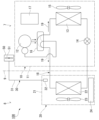
- FIG. 1 is a schematic diagram showing a schematic configuration of an air conditioner according to an embodiment.
- 1 is a schematic diagram showing an installation state of an air conditioner according to an embodiment, as viewed from the side.
- FIG. 1 is a schematic perspective view of an installation state of an air conditioner according to an embodiment.
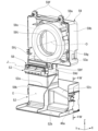
- FIG. FIG. 2 is an exploded view of the ventilation device main body according to the embodiment.
- FIG. 2 is a front view of the first member of the embodiment as viewed from the front.
- FIG. 2 is a perspective view of a fan box and a duct member according to an embodiment.
- 7 is a cross-sectional view of the duct member taken along line VII-VII in FIG. 6.
- FIG. 2 is a front view of the ventilation device main body according to the embodiment.
- FIG. 2 is a bottom view of the ventilation device main body according to the embodiment.
- 9 is a cross-sectional view of the ventilator body taken along line XX in FIG. 8.
- the drawings also show the X-axis, Y-axis, and Z-axis as appropriate.
- the X-axis shows one of the horizontal directions.
- the Y-axis shows the other of the horizontal directions.
- the Z-axis shows the vertical direction.
- the horizontal direction along the X-axis is called the "front-rear direction X”
- the horizontal direction along the Y-axis is called the "left-right direction Y”
- the vertical direction is called the "vertical direction Z”.
- the front-rear direction X, the left-right direction Y, and the vertical direction Z are mutually perpendicular directions.
- the side of the vertical direction Z toward which the Z-axis arrow points (+Z direction) is defined as the upper side
- the opposite side of the vertical direction Z to the side toward which the Z-axis arrow points (-Z direction) is defined as the lower side
- the side of the front-rear direction X toward which the X-axis arrow points (+X direction) is defined as the front
- the opposite side of the front-rear direction X to the side toward which the X-axis arrow points (-X direction) is defined as the rear.
- the side in the left-right direction Y toward which the Y-axis arrow points (+Y direction) is defined as the left
- the side opposite to the side in the left-right direction Y toward which the Y-axis arrow points (-Y direction) is defined as the right.
- Fig. 1 is a schematic diagram showing a schematic configuration of an air conditioner 100 in this embodiment.
- the air conditioner 100 includes an outdoor unit 10, an indoor unit 20, a circulation path section (refrigerant piping) 18, and a ventilation device 30.
- the outdoor unit 10 is disposed outside 7.
- the indoor unit 20 is disposed inside 8.
- the outdoor unit 10 and the indoor unit 20 are connected to each other by a circulation path section 18 through which a refrigerant 19 circulates.
- a part of the ventilation device 30 is disposed inside 8, and the other part is disposed outside 7.
- the ventilation device 30 exhausts air from the room 8 in which the indoor unit 20 is disposed to the outside 7.
- the air conditioner 100 is capable of adjusting the temperature of the air in the room 8 in which the indoor unit 20 is disposed by exchanging heat between the refrigerant 19 flowing in the circulation path section 18 and the air in the room 8 in which the indoor unit 20 is disposed.
- the refrigerant 19 include fluorine-based refrigerants or hydrocarbon-based refrigerants that have a low Global Warming Potential (GWP).
- GWP Global Warming Potential
- the outdoor unit 10 comprises an outdoor unit housing 11, a compressor 12, a heat exchanger 13, a flow control valve 14, a blower 15, a four-way valve 16, and a control unit 17.
- the outdoor unit housing 11 houses the compressor 12, the heat exchanger 13, the flow control valve 14, the blower 15, the four-way valve 16, and the control unit 17.
- the compressor 12, heat exchanger 13, flow rate control valve 14, and four-way valve 16 are provided in a portion of the circulation path 18 that is located inside the outdoor unit housing 11.
- the compressor 12, heat exchanger 13, flow rate control valve 14, and four-way valve 16 are connected by a portion of the circulation path 18 that is located inside the outdoor unit housing 11.
- the four-way valve 16 is provided in a portion of the circulation path section 18 that is connected to the discharge side of the compressor 12.
- the four-way valve 16 can reverse the direction of the refrigerant 19 flowing through the circulation path section 18 by switching a portion of the path of the circulation path section 18.
- the path connected by the four-way valve 16 is the path shown by the solid line on the four-way valve 16 in FIG. 1
- the refrigerant 19 flows through the circulation path section 18 in the direction shown by the solid arrow in FIG. 1.
- the path connected by the four-way valve 16 is the path shown by the dashed line on the four-way valve 16 in FIG. 1, the refrigerant 19 flows through the circulation path section 18 in the direction shown by the dashed arrow in FIG. 1.
- the indoor unit 20 comprises an indoor unit housing 21, a heat exchanger 22, a blower 23 as a fan, and a control unit 24.
- the indoor unit housing 21 houses the heat exchanger 22, the blower 23, and the control unit 24 inside.
- the indoor unit 20 is capable of cooling operation to cool the air in the room 8 in which the indoor unit 20 is located, and heating operation to warm the air in the room 8 in which the indoor unit 20 is located.
- the blower 23 is illustrated diagrammatically in FIG. 1.
- the refrigerant 19 flowing in the circulation path 18 flows in the direction shown by the solid arrow in Figure 1.
- the refrigerant 19 flowing in the circulation path 18 circulates through the compressor 12, the heat exchanger 13 of the outdoor unit 10, the flow control valve 14, and the heat exchanger 22 of the indoor unit 20, in that order, before returning to the compressor 12.
- the heat exchanger 13 in the outdoor unit 10 functions as a condenser
- the heat exchanger 22 in the indoor unit 20 functions as an evaporator.
- the refrigerant 19 flowing in the circulation path portion 18 flows in the direction shown by the dashed line in Figure 1.
- the refrigerant 19 flowing in the circulation path portion 18 circulates through the compressor 12, the heat exchanger 22 of the indoor unit 20, the flow control valve 14, and the heat exchanger 13 of the outdoor unit 10, in that order, before returning to the compressor 12.
- the heat exchanger 13 in the outdoor unit 10 functions as an evaporator
- the heat exchanger 22 in the indoor unit 20 functions as a condenser.
- ⁇ Indoor unit> 2 and 3 are schematic diagrams showing an installation state of the air conditioner 100 according to the embodiment.
- the indoor unit 20 is a wall-mounted indoor unit that is fixed to an upper region of a wall surface 9a of the room 8.
- the indoor unit 20 has a generally rectangular parallelepiped shape that is long in the left-right direction Y.
- the blower 23 is housed in the indoor unit housing 21.
- the blower 23 extends in the left-right direction Y.
- the blower 23 rotates around its axis of rotation by a fan motor 23a.
- the heat exchanger 22 is disposed inside the indoor unit housing 21, between the blower 23 and the indoor unit intake port 20a.
- the heat exchanger 22 extends in the left-right direction Y.
- the indoor unit housing 21 has an outer shell member 21b and an air passage member 21d.
- the outer shell member 21b is a member that constitutes part of the outer shell of the indoor unit housing 21.
- the outer shell member 21b improves the design of the appearance of the indoor unit 20.
- the outer shell member 21b is a roughly rectangular box shape that opens on the wall surface 9a side. The opening of the outer shell member 21b on the wall surface 9a side is blocked by the air passage member 21d.
- the air passage member 21d is a member that constitutes part of the air passage through which the air sucked into the indoor unit housing 21 by the blower 23 passes.
- the air passage member 21d is hooked onto an installation plate (not shown) that is fixed to the wall surface 9a on the room 8 side. This fixes the indoor unit 20 to the wall surface 9a.
- the indoor unit housing 21 has an indoor unit inlet 20a and an indoor unit outlet 20b.
- the indoor unit inlet 20a and the indoor unit outlet 20b are formed in the outer shell member 21b.
- the indoor unit inlet 20a opens upward and extends in the axial direction.
- a filter (not shown) is disposed in the indoor unit inlet 20a.
- the indoor unit outlet 20b opens toward the room 8 and extends in the axial direction.
- a wind direction control vane 25 is disposed in the indoor unit outlet 20b.
- Air from the room 8 is drawn into the indoor unit housing 21 through the indoor unit suction port 20a by the drive of the blower 23.
- the air drawn into the indoor unit housing 21 through the indoor unit suction port 20a passes through the heat exchanger 22 and is blown out into the room 8 from the indoor unit outlet 20b.
- the air passing through the indoor unit outlet 20b is blown by the air direction control vane 25 in the vertical direction Z and the left and right direction Y of the room 8.
- a control unit 24 is provided inside the indoor unit housing 21.
- the control unit 24 is disposed inside the indoor unit housing 21 at one end in the left-right direction Y.
- the control unit 24 controls the fan motor 23a, the air direction control vane 25, the heat exchanger 22, etc.
- the external shape of the indoor unit housing 21 is a rectangular column extending in the left-right direction Y.
- the indoor unit housing 21 has an upper surface 21p facing upward and a lower surface 21q facing downward.
- the indoor unit intake port 20a is provided on the upper surface 21p.
- the indoor unit exhaust port 20b is provided on the lower surface 21q.
- the indoor unit 20 is provided with a drain hose 20d.
- the tip of the drain hose 20d extends to the outside 7.
- the drain hose 20d discharges drain water that condenses on the heat exchanger 22 during cooling to the outside 7.
- the outdoor unit 10 is disposed outdoors 7.
- the outdoor unit housing 11 has an outdoor unit inlet 11b and an outdoor unit outlet 11a.
- a blower 15 sends air from the outdoor unit inlet 11b side through a heat exchanger 13 (see FIG. 1) toward the outdoor unit outlet 11a, promoting heat exchange in the heat exchanger 13.
- the outdoor unit 10 and the indoor unit 20 are connected by a circulation path section 18 and a first electrical wiring 10e.
- the circulation path section 18 is configured in a loop shape between the outdoor unit 10 and the indoor unit 20. For this reason, the circulation path section 18 connects the outdoor unit 10 and the indoor unit 20 with a pair of pipes.
- the first electrical wiring 10e includes a power supply line that supplies power to the outdoor unit 10 via the indoor unit 20, and a signal line for controlling the outdoor unit 10 and the indoor unit 20 in cooperation with each other.
- the circulation path section 18 and the first electrical wiring 10e pass through a through hole 9h provided in the wall 9 that separates the indoor space 8 from the outdoor space 7. As a result, the circulation path section 18 and the first electrical wiring 10e are drawn from the indoor space 8 to the outdoor space 7.
- the ventilation device 30 is a device that ventilates the room 8 by discharging the air inside the room 8 to the outside 7, and keeps the air inside the room 8 clean.
- the ventilation device 30 may be driven in conjunction with the indoor unit 20 and the outdoor unit 10, or may be driven independently of these.
- the ventilation device 30 has a ventilation intake section 32, a ventilation pipe 31, and a ventilation device main body 50.
- the ventilation intake section 32 is attached to the indoor unit 20 in the room 8.
- the ventilation device main body 50 is installed on the wall surface 9b of the outdoor room 7.
- the ventilation pipe 31 extends across the room 8 and the outdoor room 7.
- the ventilation intake section 32 draws in air from the room 8.
- the ventilation intake section 32 is provided on the surface of the indoor unit housing 21. In this embodiment, the ventilation intake section 32 is located on the underside 21q of the indoor unit housing 21.
- the ventilation pipe 31 is a tubular pipe.
- the ventilation pipe 31 connects the ventilation device main body 50 and the ventilation intake section 32. Therefore, one end of the ventilation pipe 31 is located inside the room 8, and the other end is located outside the room 7.
- the ventilation pipe 31 passes through the inside of the indoor unit housing 21 and the through hole 9h in the wall 9 and is drawn out to the outside the room 7.
- FIG. 4 is an exploded view of the ventilator main body 50.
- the direction perpendicular to the wall surface 9b to which the ventilation device main body 50 is attached is the front-rear direction X
- the direction perpendicular to the vertical direction Z and the front-rear direction is the left-right direction Y.
- the direction perpendicular to the wall surface 9b that moves away from the wall surface 9b is called the forward direction (+X direction)
- the direction approaching the wall surface 9b is called the rearward direction (-X direction).
- the left and right are defined based on the posture of the observer facing forward (+X direction).
- the left hand side of the observer facing the opposite side (+X direction) of the wall surface 9b is called the left side (+Y direction), and the right hand side is called the right side (-Y direction).
- the left-right direction Y of the ventilation device main body 50 and the left-right direction of the outdoor unit 10 coincide with each other, but these left-right directions Y do not necessarily have to coincide with each other.
- the ventilation device main body 50 has a base 80, a joint member 75, a backflow prevention valve 53, a ventilation fan 51, a duct member 52, and a case 40.
- the case 40 is box-shaped and opens to the rear.
- the case 40 is supported by a base 80.
- the case 40 covers the base 80 of the ventilation device main body 50, the joint member 75, the backflow prevention valve 53, the ventilation fan 51, and the duct member 52. In this way, the case 40 protects each part of the ventilation device main body 50.
- the base 80 is fixed to the wall surface 9b by fixing screws (not shown).
- the base 80 supports other components of the ventilation device main body 50.
- the ventilation pipe 31 (see FIG. 3) is connected to the base 80.
- the base 80 has a base main body 60, an installation plate 70, and a drain valve 69.
- the mounting plate 70 is a plate-shaped member made of sheet metal.
- the mounting plate 70 protects the wall surface 9b.
- the mounting plate 70 has a plate body 70a and a lower end plate portion 70c.
- the plate body 70a is arranged along the wall surface 9b.
- the plate body 70a is arranged between the base body 60 and the wall surface 9b.
- the upper end of the case 40 is engaged with the upper end of the plate body 70a.
- the plate body 70a has a fixing surface 70f facing the wall surface 9b.
- the fixing surface 70f is a flat surface.
- the mounting plate 70 is fixed to the wall surface 9b at the fixing surface 70f. In this embodiment, a case where the fixing surface 70f directly contacts the wall surface 9b will be described. However, a gap may be provided between the fixing surface 70f and the wall surface 9b by, for example, interposing a washer between the fixing surface 70f and the wall surface 9b.
- the lower end plate portion 70c is formed by bending the lower end portion of the mounting plate 70 forward.
- the lower end plate portion 70c is connected to the lower end of the plate body 70a.
- the case 40 is screwed to the lower end plate portion 70c.
- a notch portion 70d is provided in the lower end plate portion 70c. The notch portion 70d extends rearward from the front end of the lower end plate portion 70c.
- the base body 60 is fixed to the surface of the mounting plate 70 facing forward (+X direction).
- An intake air passage F is provided inside the base body 60.
- the base body 60 has a first member 61 and a second member 62 that are assembled to each other in the front-to-rear direction X.
- the intake air passage F is mainly formed between the first member 61 and the second member 62.
- the first member 61 constitutes the rear portion of the base body 60. Meanwhile, the second member 62 constitutes the front portion of the base body 60.
- the second member 62 supports the ventilation fan 51.
- the second member 62 is provided with an opening 62a that penetrates the second member 62 in the front-rear direction X.
- the downstream end of the intake air duct F opens forward at the opening 62a.
- the opening 62a is covered by the ventilation fan 51.
- FIG. 5 is a front view of the first member 61 as viewed from the front.
- the intake air passage F is formed in a U-shape when viewed from the front-rear direction X.
- the intake air passage F has an inlet portion 60p, an upstream region 60a, a turn-back region 60c, a downstream region 60b, a forward bent portion 60q, and an opening 62a.
- the inlet portion 60p is connected to the ventilation pipe 31. Air flows into the inlet portion 60p from the ventilation pipe 31.
- the upstream region 60a extends downward from the inlet portion 60p.
- the turn-back region 60c extends in the left-right direction Y.
- the turn-back region 60c connects the lower end of the upstream region 60a to the lower end of the downstream region 60b.
- the right end (-Y direction) of the turn-back region 60c is connected to the upstream region 60a.
- the left end (+Y direction) of the turn-back region 60c is connected to the downstream region 60b.
- the downstream region 60b extends upward from the folded-back region 60c.
- a forward bent portion 60q is provided at the upper end of the downstream region 60b.
- the forward bent portion 60q is bent forward (in the +X direction).
- An opening 62a is provided in front of the forward bent portion 60q. The opening 62a opens forward.
- a ventilation fan 51 (see Figure 4) is connected to the opening 62a. In this way, the intake duct F connects the ventilation pipe 31 and the ventilation fan 51.
- the base body 60 has a bottom 60d located below the intake air passage F.
- the bottom 60d forms the lower wall of the intake air passage F.
- the bottom 60d is provided with a drainage hole 61h, a valve housing portion 61k, and an induction hole 61j.
- the drain hole 61h is located below the intake air duct F.
- the drain hole 61h opens to the bottom surface 61c located below the folded region 60c of the wall surface surrounding the intake air duct F.
- the drain hole 61h extends downward from the folded region 60c to connect the folded region 60c to the valve accommodating portion 61k.
- the valve accommodating portion 61k is a space provided below the intake air duct F to accommodate the drain valve 69.
- the induction hole 61j connects the valve accommodating portion 61k to the outside of the base body.
- the drain valve 69 is disposed inside the valve housing 61k.
- the drain valve 69 faces the opening at the lower end of the drain hole 61h in the vertical direction Z.
- the drain valve 69 closes the drain hole 61h when the ventilation fan 51 is driven and negative pressure is created in the intake air duct F.
- the drain valve 69 opens the drain hole 61h when the ventilation fan 51 is stopped.
- the drain valve 69 opens the drain hole 61h due to the weight of the water, even if the ventilation fan 51 is driven.
- the ventilation pipe 31 and the ventilation device main body 50 of this embodiment are arranged outside 7.
- the ventilation device 30 When the ventilation device 30 is operated while the air conditioner 100 is heating the room, for example in winter, the heated air from the room 8 passes through the ventilation pipe 31 and the ventilation device main body 50. This air is cooled by the outside air, causing condensation to occur in the ventilation pipe 31 and the ventilation device main body 50.
- the condensed water accumulates at the lower end of the folded-back area 60c in the intake air duct F.
- the condensed water in the intake air duct F flows into the valve housing portion 61k through the drain hole 61h.
- the condensed water in the valve housing portion 61k further flows downward through the guide hole 61j and is drained from the drain outlet 46h (see FIG. 9) described later.
- the ventilation fan 51 is fixed to the base body 60 from the front (+X direction).
- the ventilation fan 51 is connected to the ventilation pipe 31 via the intake air passage F of the base body 60.
- the ventilation fan 51 may be directly connected to the ventilation pipe 31.
- the ventilation fan 51 and the ventilation pipe 31 may also be connected via another separate member.
- the ventilation fan 51 has a cylindrical rotor 51a centered on a central axis O extending in the front-rear direction X, a fan motor 51b that rotates the rotor 51a, a fan box 59 that houses the rotor 51a and the fan motor 51b, and a terminal block 51e.
- the ventilation fan 51 in this embodiment is a so-called sirocco fan.
- the ventilation fan 51 sends air from the inner diameter side to the outer diameter side of the rotor 51a by rotating the rotor 51a.
- the fan box 59 is fixed to the surface of the base body 60 facing forward (+X direction).
- a rotor 51a and a fan motor 51b are arranged inside the fan box 59.
- the fan box 59 is provided with a fan intake port 59t (see FIG. 6) that is connected to the opening 62a of the base body 60.
- the ventilation fan 51 draws air from the intake air duct F of the base body 60 at the fan intake port as the rotor 51a rotates.
- the fan box 59 also has a fan duct portion 59d that extends downward.
- the fan duct portion 59d is connected to the duct member 52 at its lower end.
- the ventilation fan 51 sends air from the fan duct portion 59d into the duct member 52.
- the terminal block 51e supports multiple terminal connections (not shown) that are connected to the fan motor 51b. These terminal connections are connected to terminals of electrical wiring (not shown) extending from the indoor unit 20 or the outdoor unit 10.
- FIG 6 is a perspective view of the fan box 59, the backflow prevention valve 53, and the duct member 52.
- the fan box 59 has a cylindrical portion 59a, a frame portion 59b, an annular plate portion 59c, and a fan duct portion 59d.
- the cylindrical portion 59a is cylindrical and centered on the central axis O of the rotor 51a (see FIG. 4).
- the cylindrical portion 59a surrounds the rotor 51a from the radial outside.
- the fan duct portion 59d is connected to the cylindrical portion 59a.
- the connection portion of the cylindrical portion 59a with the fan duct portion 59d is open in the radial direction, and the space inside the cylindrical portion 59a is connected to the air passage inside the fan duct portion 59d.
- the frame portion 59b is box-shaped and opens to the rear (-X direction).
- the frame portion 59b constitutes the outer shell of the fan box 59.
- the frame portion 59b closes the front (+X direction) opening of the cylindrical portion 59a.
- the frame portion 59b is also formed in a frame shape when viewed from the front-rear direction X, and surrounds the cylindrical portion 59a from the radial outside of the central axis O.
- the frame portion 59b is provided with a plurality of fixing portions 59f for fixing the fan box 59 to the base main body 60 (see Figure 4).
- the annular plate portion 59c is a plate extending from the rear end (-X direction) of the cylindrical portion 59a toward the inside in the radial direction of the central axis O.
- the annular plate portion 59c is provided with a circular fan intake port 59t centered on the central axis O.
- a buffer member 59g is adhesively fixed to the surface of the annular plate portion 59c facing rearward (-X direction).
- the buffer member 59g is annular and surrounds the fan intake port 59t.
- the buffer member 59g is a sponge-like member.
- the buffer member 59g is sandwiched and compressed between the fan box 59 and the base body 60. The buffer member 59g prevents air from leaking from the path that flows from the base body 60 to the fan intake port 59t.
- the fan duct portion 59d extends in the vertical direction Z.
- the fan duct portion 59d also extends in a tangential direction to the cylindrical portion 59a.
- the upper end 59j of the fan duct portion 59d is connected to the cylindrical portion 59a.
- the lower end 59k of the fan duct portion 59d opens downward.
- the swirling flow centered on the central axis O formed by the rotor 51a flows in the circumferential direction of the central axis O along the inner surface of the cylindrical portion 59a.
- the air forming the swirling flow flows into the fan duct portion 59d and flows downward inside the fan duct portion 59d.
- the expression "extending in a specific direction” means that the direction in which the object (or space) extends has a component in that specific direction over its entire length, and is not to be interpreted in a restrictive sense as being parallel to that specific direction over its entire length.
- the backflow suppression valve 53 is rotatably supported by a valve support portion 58 provided on the fan duct portion 59d.
- the backflow suppression valve 53 rotates around a rotation axis J extending in the left-right direction Y.
- the backflow suppression valve 53 has a plate body 53a arranged inside the fan duct portion 59d.
- the plate body 53a is displaced while changing the angle of the plate surface as the backflow suppression valve 53 rotates around the rotation axis J.
- the plate body 53a is arranged intersecting the extension direction of the fan duct portion 59d and blocks the air passage in the fan duct portion 59d.
- the plate body 53a When a downward air flow occurs in the air passage as the ventilation fan 51 is driven, the plate body 53a is pushed by the air and rotates downward to open the air passage. In this way, the backflow suppression valve 53 opens the air passage when the ventilation fan 51 is driven and closes the air passage when the ventilation fan 51 is stopped.
- the backflow prevention valve 53 prevents wind, rain, or insects and other living things from entering the interior of the ventilation fan 51 when the ventilation fan 51 is stopped.
- the duct member 52 is disposed below the fan duct portion 59d.
- the duct member 52 extends in the vertical direction Z.
- the duct member 52 forms an exhaust air duct E between the lower end 59k of the fan duct portion 59d and the exhaust port 46a. That is, the fan duct portion 59d is provided with an exhaust air duct E that connects the ventilation fan 51 and the exhaust port 46a.
- the exhaust air duct E extends in the vertical direction Z. The exhaust air duct E guides the air blown out from the ventilation fan 51 to the outside of the ventilation device 30.
- FIG. 7 is a cross-sectional view of the duct member 52 taken along the line VII-VII in FIG.
- the duct member as a whole extends in the vertical direction Z.
- the duct member 52 has a closure plate 52k, a first duct portion 52b, an extension portion 52c, and a second duct portion 52d that are aligned in the vertical direction Z.
- the first duct section 52b, the extension section 52c, and the second duct section 52d are arranged in series in the vertical direction Z.
- An exhaust air duct E is provided inside the first duct section 52b, the extension section 52c, and the second duct section 52d.
- the first duct section 52b opens upward and connects to the fan duct section 59d of the ventilation fan 51. Meanwhile, the second duct section 52d opens downward and connects to the exhaust port 46a.
- the extension section 52c connects between the first duct section 52b and the second duct section 52d.
- the blocking plate 52k is arranged perpendicular to the vertical direction Z. The blocking plate 52k extends rearward (in the -X direction) from the lower opening edge of the second duct section 52d.
- cross-sectional shapes of the flow paths of the first duct section 52b, the extension section 52c, and the second duct section 52d are all rectangular, but the cross-sectional lines are different from one another.
- the "cross-sectional shape of the flow path" here means a cross-section perpendicular to the air flow of the exhaust air duct E, and is a cross-section perpendicular to the vertical direction Z in the first duct section 52b, the extension section 52c, and the second duct section 52d.
- the first duct section 52b, the extension section 52c, and the second duct section 52d each have four side panels that surround the exhaust air duct E from the front-to-back direction X and the left-to-right direction Y.
- the first duct section 52b, the extension section 52c, and the second duct section 52d each have a pair of side panels that are arranged in the front-to-back direction X of the exhaust air duct E, and these side panels are arranged perpendicular to the front-to-back direction X.
- the first duct section 52b has a first left side plate 52f arranged to the left (+Y direction) of the exhaust air duct E, and a first right side plate 52e arranged to the right (-Y direction) of the exhaust air duct E.
- the extension section 52c has an extended left side plate 52h arranged to the left (+Y direction) of the exhaust air duct E, and an extended right side plate 52g arranged to the right (-Y direction) of the exhaust air duct E.
- the second duct section 52d has a second left side plate 52j arranged to the left (+Y direction) of the exhaust air duct E, and a second right side plate 52i arranged to the right (-Y direction) of the exhaust air duct E.
- the first left side plate 52f, the extended left side plate 52h, and the second left side plate 52j are perpendicular to the left-right direction Y and are arranged on approximately the same plane. In other words, the first left side plate 52f, the extended left side plate 52h, and the second left side plate 52j extend in the vertical direction Z as a single plate.
- the first right side plate 52e and the second right side plate 52i are positioned perpendicular to the left-right direction Y.
- the second right side plate 52i is positioned to the right (-Y direction) of the first right side plate 52e.
- the extended right side plate 52g connects the first right side plate 52e and the second right side plate 52i.
- the extended right side plate 52g inclines to the right (-Y direction) as it extends downward. Therefore, the extended right side plate 52g gradually moves away from the extended left side plate 52h as it extends downward.
- the extension section 52c widens the exhaust air duct E in the left-right direction Y as it moves downward.
- the cross-sectional area of the exhaust air duct E in the second duct section 52d is larger than the cross-sectional area of the exhaust air duct E in the first duct section 52b.
- the wind speed of the air flowing through the exhaust air duct E gradually slows down as it passes through the extension section 52c. For this reason, the wind speed of the air passing through the exhaust air duct E in the second duct section 52d is lower than the wind speed of the air passing through the exhaust air duct E in the first duct section 52b.
- Fig. 8 is a front view of the ventilation device main body 50.
- Fig. 9 is a bottom view of the ventilation device main body 50.
- the case 40 has a bottom plate 46.
- the bottom plate 46 covers the internal space of the case 40 from below.
- the bottom plate 46 is disposed perpendicular to the vertical direction Z.
- the bottom plate 46 is provided with an opening 46b penetrating the bottom plate 46 in the vertical direction Z.
- the opening 46b is rectangular in shape with its longitudinal direction in the left-right direction Y.
- An exhaust port 46a is disposed in an area of the opening 46b away from the wall 9. That is, the exhaust port 46a is provided in the case 40.
- the area of the opening 46b facing the wall 9 is blocked by a blocking plate 52k of the duct member 52.
- the underside of the blocking plate 52k is exposed downward from the opening 46b.
- a label, such as a warning notice, can be affixed to the underside of the blocking plate 52k.
- the exhaust port 46a opens downward.
- the exhaust port 46a is connected to an opening located at the lower end of the second duct section 52d of the duct member 52. Air flowing downward through the exhaust air duct E of the duct member 52 is exhausted from the exhaust port 46a to the outside of the ventilation device main body 50.
- the exhaust port 46a is covered by a mesh-like grill G.
- the grill G is fixed to the lower end of the second duct section 52d. The grill G prevents living organisms or foreign objects from entering the inside of the ventilation device main body 50 through the exhaust port 46a.
- the exhaust port 46a has a rectangular shape with its longitudinal direction in the left-right direction Y.
- the dimension w2 of the exhaust port 46a in the left-right direction Y is greater than the dimension w1 in the front-rear direction X.
- the exhaust port 46a is also positioned biased toward the front (front) of the bottom plate 46 of the case 40, away from the fixed surface 70f. According to this embodiment, the exhaust port 46a can be spaced away from the wall surface 9b while ensuring that the opening area of the exhaust port 46a is sufficiently wide in the left-right direction Y. This makes it possible to prevent dirt from adhering to the wall surface 9b due to the exhaust air blown out from the exhaust port 46a.
- the distance d1 between the fixing surface 70f and the exhaust port 46a is greater than the dimension w1 of the exhaust port 46a in the front-rear direction X.
- the distance d1 between the fixing surface 70f and the exhaust port 46a is greater than half the dimension d2 of the ventilation device main body 50 in the front-rear direction X.
- the distance d1 between the fixing surface 70f and the exhaust port 46a is greater than the diameter D of the ventilation piping 31.
- FIG. 10 is a cross-sectional view of the ventilator body 50 taken along line XX in FIG. 10, the base body 60 is disposed along the fixed surface 70f. Therefore, the intake airflow duct F in the base body 60 also extends along the fixed surface 70f. On the other hand, the exhaust airflow duct E extends in the vertical direction Z along the fixed surface 70f, but is disposed farther away from the fixed surface 70f than the intake airflow duct F. The intake airflow duct F and the exhaust airflow duct E overlap when viewed from the front-rear direction X.
- the intake air duct F is disposed between the exhaust air duct E and the fixed surface 70f in the front-rear direction X. This makes it easier to align the ventilation pipe 31 connected to the intake air duct F along the wall surface 9b, and allows the exhaust air duct E to be disposed away from the wall surface 9b, and the exhaust port 46a connected to the exhaust air duct E can be moved away from the wall surface 9b.
- the bottom plate 46 of the case 40 has a pair of screw holes 46c aligned in the left-right direction Y.
- the pair of screw holes 46c penetrate the bottom plate 46 in the vertical direction Z.
- the lower end plate portion 70c of the mounting plate 70 overlaps above the bottom plate 46.
- Fixing screws 46f are inserted into the pair of screw holes 46c.
- the fixing screws 46f screw the bottom plate 46 to the lower end plate portion 70c.
- the fixing surface 70f of the mounting plate 70 faces the wall surface 9b.
- the fixing surface 70f also extends along the wall surface 9b.
- the rear end edge 46e of the bottom plate 46 faces the wall surface 9b via a gap.
- the lower end plate portion 70c of the mounting plate 70 is provided with a notch 70d.
- the opening surrounded by the rear end edge 46e of the bottom plate 46 and the notch 70d functions as a drain port 46h. That is, the ventilation device main body 50 is provided with a drain port 46h that opens downward.
- the bottom 60d of the base body 60 is provided with guide holes 61j.
- the guide holes 61j guide the condensation water drained from the intake air duct F to the underside 60f of the bottom 60d.
- the condensation water flows downward along the underside 60f of the bottom 60d and the front-facing surface of the plate body 70a of the mounting plate 70, reaches the drain outlet 46h, and is drained to the outside of the case 40.
- the drain outlet 46h is located at the rear end of the ventilation device body 50 (the end closer to the fixed surface 70f in the front-rear direction X). Therefore, the condensation water drained from the drain outlet 46h flows downward along the wall surface 9b.
- the exhaust port 46a is positioned farther from the fixed surface 70f than the drain port 46h. As a result, even if the exhaust air blown out from the exhaust port 46a hits the condensed water drained from the drain port 46h, the condensed water flows toward the wall 9 and runs down the wall 9, making it less likely for the condensed water to scatter around.
- the comparison of the distance of the exhaust port 46a and the drain port 46h to the fixed surface 70f is performed by comparing the minimum distance from a point on a virtual surface including the fixed surface 70f to the exhaust port 46a and the drain port 46h.
- the position of the drain outlet 46h in the left-right direction Y overlaps with the right end (-Y direction) of the exhaust outlet 46a. Furthermore, at least a portion of the drain outlet 46h is positioned offset in the left-right direction Y with respect to the exhaust outlet 46a.
- the wind speed of the exhaust air exhausted from the exhaust outlet 46a is slower at the ends in the left-right direction Y than at the center in the left-right direction Y.
- the exhaust air duct E of this embodiment widens in the left-right direction Y toward the exhaust port 46a. This widens the opening area of the exhaust port 46a in the left-right direction Y, and the wind speed of the exhaust air blown out from the exhaust port 46a is suppressed. By suppressing the wind speed of the exhaust air, adhesion of dirt to the wall surface 9b is reduced. Furthermore, by widening the exhaust port 46a in the left-right direction Y, the distance between the exhaust port 46a and the wall surface 9b is ensured even if the opening area is secured large. In other words, according to this embodiment, dirt on the wall surface 9b caused by the exhaust air blown out from the exhaust port 46a can be suitably suppressed. In addition, by suppressing the wind speed of the exhaust air exhausted from the exhaust port 46a, the scattering of condensed water drained from the drainage port 46h can also be suitably suppressed.
- the air conditioner 100 of this embodiment includes an indoor unit 20, an outdoor unit 10, a circulation path section (refrigerant piping) 18, and a ventilation device 30.
- the indoor unit 20 is installed in the room 8 and has a heat exchanger (first heat exchanger) 22.
- the outdoor unit 10 is installed in the outdoor 7 and has a heat exchanger (second heat exchanger) 13.
- the circulation path section 18 passes through a through hole 9h in a wall 9 that separates the room 8 from the outdoor 7, and connects the heat exchanger 22 of the indoor unit 20 to the heat exchanger 13 of the outdoor unit 10.
- the ventilation device 30 ventilates the air in the room 8.
- the ventilation device 30 includes a ventilation pipe 31 and a ventilation device main body 50.
- the ventilation pipe 31 is drawn from the indoor unit 20 to the outdoor 7 through the through hole 9h.
- the ventilation device main body 50 is fixed to the wall surface of the outdoor 7.
- the ventilation device main body 50 has a ventilation fan 51, an exhaust port 46a, an intake air duct F, an exhaust air duct E, a drain port 46h, and a fixing surface.
- the exhaust port 46a opens downward.
- the intake air duct F connects the ventilation pipe 31 and the ventilation fan 51.
- the exhaust air duct E connects the ventilation fan 51 and the exhaust port 46a.
- the drain port 46h opens downward.
- the drain port 46h drains water that accumulates in the intake air duct F.
- the fixing surface 70f faces the wall surface 9b and extends along the wall surface 9b.
- the exhaust port 46a is disposed farther from the fixing surface 70f than the drain port 46h.
- the ventilation fan 51 is disposed inside the ventilation device main body 50 outside the room 7, so that noise caused by the operation of the ventilation fan 51 is unlikely to be transmitted to the room 8, and the room 8 can be kept quiet.
- condensation water is likely to occur in the intake air duct F (see FIG. 5) that guides air to the ventilation fan 51.
- the condensation water in the intake air duct F can be drained to the outside of the ventilation device main body 50, and abnormal noise and mold growth caused by the condensation water in the intake air duct F can be suppressed.
- the exhaust port 46a is disposed farther from the wall surface 9b than the drainage port 46h. This separates the exhaust port 46a from the wall surface 9b, preventing dirt contained in the exhaust air blown out from the exhaust port 46a from adhering to the wall surface 9b.
- the exhaust air blown out from the exhaust port 46a hits the condensed water drained from the drainage port 46h, it flows toward the wall 9 and runs down the wall 9. This prevents the condensed water from scattering around due to the wind pressure of the exhaust air.
- the exhaust port 46a has a larger dimension in the left-right direction Y than in the front-rear direction X.
- This configuration allows the opening area of the exhaust port 46a to be increased while ensuring the distance between the exhaust port 46a and the wall surface 9b.
- the wind speed of the exhaust air blown out from the exhaust port 46a can be reduced, and the scattering of condensed water caused by the exhaust air blown out from the exhaust port 46a can be suppressed.
- dirt contained in the exhaust air is less likely to adhere to the wall surface 9b, making it easier to keep the wall surface 9b clean.
- the distance d1 between the fixing surface 70f and the exhaust port 46a is greater than the dimension w1 of the exhaust port 46a in the front-rear direction X.
- the distance between the fixing surface 70f and the exhaust port 46a is greater than half the dimension d2 in the front-to-rear direction X of the ventilation device main body 50.
- the exhaust port 46a can be positioned on the underside of the ventilation device main body 50, biased away from the wall surface 9b, making it difficult for the exhaust air to hit the wall surface 9b and reducing dirt on the wall surface 9b.
- the distance between the fixing surface 70f and the exhaust port 46a is greater than the diameter of the ventilation pipe 31.
- the exhaust port 46a can be positioned farther from the wall surface 9b than the ventilation pipe 31 that is aligned along the wall surface 9b, making it less likely for the exhaust air to hit the wall surface 9b and reducing dirt on the wall surface 9b.
- the exhaust duct E widens in the left-right direction Y as it moves downward.
- the wind speed of the air flowing through the exhaust duct E can be reduced as it moves toward the exhaust port 46a, and the wind speed of the exhaust air blown out from the exhaust port 46a can be reduced. This makes it possible to suppress the scattering of condensation water caused by the exhaust, and also makes it difficult for dirt contained in the exhaust air to adhere to the wall surface 9b.
- the drain outlet 46h is located at the end closer to the fixed surface 70f of the ventilation device main body 50 in the front-rear direction X.
- the drain outlet 46h can be separated from the exhaust outlet 46a as far as possible in the front-rear direction X, and it is possible to prevent the exhaust air from the exhaust outlet 46a from hitting the condensed water drained from the drain outlet 46h.
- the condensed water drained from the drain outlet 46h can be easily made to flow to the wall surface 9b.
- the intake duct F extends along the fixed surface 70f between the fixed surface 70f and the exhaust duct E.
- the intake duct F is aligned along the fixed surface 70f, which makes it easier to align the ventilation pipe 31 connected to the intake duct F along the wall surface 9b.
- the exhaust duct E can be positioned farther away from the wall surface 9b than the intake duct F, and the exhaust port 46a connected to the exhaust duct E can be moved away from the wall surface 9b.
- the intake duct F and the exhaust duct E are overlapped when viewed from the front-to-rear direction X, and the ventilation device main body 50 can be made smaller in size in the vertical direction Z and the left-to-right direction Y.
- the present disclosure is not limited to the configurations of the above-described embodiments.
- the exhaust port 46a is rectangular.
- the shape of the drain port 46h is not limited to that in the above embodiment, and may be, for example, elliptical.
- the drain outlet 46h is described as being formed by the case 40 and the mounting plate 70, but the drain outlet 46h may also be a through hole provided in the case 40, the mounting plate 70, or another component.
- the exhaust air duct E extends in the vertical direction Z.
- the exhaust air duct E is not limited in the direction in which it extends, and may have a portion that extends in the horizontal direction, for example.
- the ventilation fan 51 is a sirocco fan, but the type of the ventilation fan 51 is not limited.
Landscapes
- Engineering & Computer Science (AREA)
- Chemical & Material Sciences (AREA)
- Combustion & Propulsion (AREA)
- Mechanical Engineering (AREA)
- General Engineering & Computer Science (AREA)
- Air-Flow Control Members (AREA)
Abstract
An air conditioner provided with: an indoor unit that is installed indoors and that has a first heat exchanger; an outdoor unit that is installed outdoors and that has a second heat exchanger; a refrigerant pipe that passes through a through hole in a wall separating the indoors and the outdoors and that connects the first heat exchanger and the second heat exchanger; and a ventilation device that ventilates indoor air. The ventilation device includes: a ventilation pipe that passes through the through hole from the indoors and is drawn out to the outdoors; and a ventilation device body that is fixed to an outdoor wall surface. The ventilation device body includes: a ventilation fan; an exhaust port that opens downward; an intake air passage that connects the ventilation pipe and the ventilation fan; an exhaust air passage that connects the ventilation fan and the exhaust port; a drain port that opens downward and drains water collected inside of the intake air passage; and a fixed surface that faces the wall surface and extends along the wall surface. The exhaust port is disposed farther from the fixed surface than the drain port.
Description
本開示は、空気調和機に関する。
This disclosure relates to air conditioners.
近年、室内の空気を室内機の内部の熱交換器により熱交換させて室内に供給することで室内を快適な温度環境に維持する空気調和機が一般的となっている。このような空気調和機は、室内機によって室内の空気を循環させるのみで室外との間で換気を行うことがないため、室内が長時間密閉的状態にあると室内空気が汚れてしまう。そこで、室内空気を室外に排出する換気ユニットを備えた空気調和機が開示されている(例えば、特許文献1参照)。
In recent years, air conditioners that maintain a comfortable temperature environment indoors by exchanging heat with indoor air using a heat exchanger inside the indoor unit and supplying it indoors. Such air conditioners only circulate the indoor air using the indoor unit and do not ventilate the air between the indoors and the outside, so if the room remains sealed for a long period of time, the indoor air becomes polluted. For this reason, air conditioners equipped with a ventilation unit that exhausts indoor air to the outside have been disclosed (see, for example, Patent Document 1).
室内の静音性を確保するために、換気装置の換気ファンは、室外に配置することが好ましい。この場合、例えば冬季に暖房を動作させると、室内と換気ファンとを繋ぐ換気配管内の空気が外気に冷やされて換気配管内に結露を発生させる。このため、換気装置には、結露水を室外の地面に向けて排水する下向きの排水口を設けることが望ましい。また、換気装置には、空気を排気するための排気口が設けられる。排気口は、雨水の侵入を抑制するため下向きとすることが望ましい。換気装置において排水口と排気口とを共に下向きに設けると、排気口から吹き出される空気によって排水口から排水される水が飛散する虞がある。
In order to ensure quietness inside the room, it is preferable to place the ventilation fan of the ventilation device outside. In this case, for example, when the heater is turned on in winter, the air in the ventilation pipe connecting the room to the ventilation fan is cooled by the outside air, causing condensation to form inside the ventilation pipe. For this reason, it is preferable that the ventilation device be provided with a downward-facing drain outlet that drains the condensation water toward the ground outside. The ventilation device is also provided with an exhaust port for discharging air. The exhaust port is preferably directed downward to prevent rainwater from entering. If the drain outlet and exhaust port are both provided facing downward in the ventilation device, there is a risk that the water drained from the drain port will be scattered by the air blown out from the exhaust port.
本開示は、上記事情に鑑みて、排水口から排水される水の飛散を抑制できる空気調和機の提供を目的とする。
In consideration of the above circumstances, the present disclosure aims to provide an air conditioner that can suppress the splashing of water discharged from the drain outlet.
本開示に係る空気調和機の一つの態様は、室内に設置され、第1熱交換器を有する室内機と、室外に設置され、第2熱交換器を有する室外機と、前記室内と前記室外とを隔てる壁の貫通孔を通り前記第1熱交換器と前記第2熱交換器とを繋ぐ冷媒配管と、前記室内の空気を換気する換気装置と、を備え、前記換気装置は、前記室内から前記貫通孔を通り前記室外に引き出される換気配管と、前記室外の壁面に固定される換気装置本体と、を備え、前記換気装置本体は、換気ファンと、下方に向けて開口する排気口と、前記換気配管と前記換気ファンを繋ぐ吸気風路と、前記換気ファンと前記排気口とを繋ぐ排気風路と、下方に向けて開口し前記吸気風路内に溜る水を排水する排水口と、前記壁面に対向し前記壁面に沿って延びる固定面と、を有し、前記排気口は、前記排水口よりも前記固定面から離れて配置される。
One aspect of the air conditioner according to the present disclosure includes an indoor unit installed indoors and having a first heat exchanger, an outdoor unit installed outdoors and having a second heat exchanger, a refrigerant pipe that passes through a through hole in a wall separating the indoor and outdoor spaces and connects the first heat exchanger and the second heat exchanger, and a ventilation device that ventilates the air in the indoor space, the ventilation device includes a ventilation pipe that passes through the through hole from the indoor space to the outdoor space and is drawn out to the outdoor space, and a ventilation device main body that is fixed to the outdoor wall surface, the ventilation device main body includes a ventilation fan, an exhaust port that opens downward, an intake air duct that connects the ventilation pipe and the ventilation fan, an exhaust air duct that connects the ventilation fan and the exhaust port, a drain port that opens downward and drains water that accumulates in the intake air duct, and a fixed surface that faces the wall surface and extends along the wall surface, and the exhaust port is disposed farther from the fixed surface than the drain port.
本開示によれば、排水口から排水される水の飛散を抑制できる空気調和機を提供できる。
This disclosure provides an air conditioner that can suppress the splashing of water discharged from the drain outlet.
以下、図面を参照しながら、本開示の実施の形態について説明する。なお、本開示の範囲は、以下の実施の形態に限定されず、本開示の技術的思想の範囲内で任意に変更可能である。また、以下の図面においては、各構成をわかりやすくするために、各構造における縮尺および数などを、実際の構造における縮尺および数などと異ならせる場合がある。
Below, an embodiment of the present disclosure will be described with reference to the drawings. Note that the scope of the present disclosure is not limited to the following embodiment, and can be modified as desired within the scope of the technical ideas of the present disclosure. In addition, in the following drawings, the scale and numbers of each structure may differ from the scale and numbers of the actual structure in order to make each configuration easier to understand.
また、図面には、適宜、X軸、Y軸、およびZ軸を示している。X軸は、水平方向のうちの一方向を示している。Y軸は、水平方向のうちの他の一方向を示している。Z軸は、鉛直方向を示している。以下の説明においては、X軸に沿った水平方向を“前後方向X”と呼び、Y軸に沿った水平方向を“左右方向Y”と呼び、鉛直方向を“鉛直方向Z”と呼ぶ。前後方向X、左右方向Y、および鉛直方向Zは、互いに直交する方向である。以下の説明においては、鉛直方向ZのうちZ軸の矢印が向く側(+Z方向)を上方とし、鉛直方向ZのうちZ軸の矢印が向く側と逆側(-Z方向)を下方とする。また、前後方向XのうちX軸の矢印が向く側(+X方向)を前方とし、前後方向XのうちX軸の矢印が向く側と逆側(-X方向)を後方とする。また、左右方向YのうちY軸の矢印が向く側(+Y方向)を左方とし、左右方向YのうちY軸の矢印が向く側と逆側(-Y方向)を右方とする。
The drawings also show the X-axis, Y-axis, and Z-axis as appropriate. The X-axis shows one of the horizontal directions. The Y-axis shows the other of the horizontal directions. The Z-axis shows the vertical direction. In the following description, the horizontal direction along the X-axis is called the "front-rear direction X", the horizontal direction along the Y-axis is called the "left-right direction Y", and the vertical direction is called the "vertical direction Z". The front-rear direction X, the left-right direction Y, and the vertical direction Z are mutually perpendicular directions. In the following description, the side of the vertical direction Z toward which the Z-axis arrow points (+Z direction) is defined as the upper side, and the opposite side of the vertical direction Z to the side toward which the Z-axis arrow points (-Z direction) is defined as the lower side. In addition, the side of the front-rear direction X toward which the X-axis arrow points (+X direction) is defined as the front, and the opposite side of the front-rear direction X to the side toward which the X-axis arrow points (-X direction) is defined as the rear. Additionally, the side in the left-right direction Y toward which the Y-axis arrow points (+Y direction) is defined as the left, and the side opposite to the side in the left-right direction Y toward which the Y-axis arrow points (-Y direction) is defined as the right.
<全体構成>
図1は、本実施の形態における空気調和機100の概略構成を示す模式図である。図1に示すように、空気調和機100は、室外機10と、室内機20と、循環経路部(冷媒配管)18と、換気装置30と、を備える。室外機10は、室外7に配置されている。室内機20は、室内8に配置されている。室外機10と室内機20とは、冷媒19が循環する循環経路部18によって互いに接続されている。換気装置30は、一部が室内8に、他の部分が室外7に配置されている。換気装置30は、室内機20が配置される室内8の空気を室外7に排出する。 <Overall composition>
Fig. 1 is a schematic diagram showing a schematic configuration of anair conditioner 100 in this embodiment. As shown in Fig. 1, the air conditioner 100 includes an outdoor unit 10, an indoor unit 20, a circulation path section (refrigerant piping) 18, and a ventilation device 30. The outdoor unit 10 is disposed outside 7. The indoor unit 20 is disposed inside 8. The outdoor unit 10 and the indoor unit 20 are connected to each other by a circulation path section 18 through which a refrigerant 19 circulates. A part of the ventilation device 30 is disposed inside 8, and the other part is disposed outside 7. The ventilation device 30 exhausts air from the room 8 in which the indoor unit 20 is disposed to the outside 7.
図1は、本実施の形態における空気調和機100の概略構成を示す模式図である。図1に示すように、空気調和機100は、室外機10と、室内機20と、循環経路部(冷媒配管)18と、換気装置30と、を備える。室外機10は、室外7に配置されている。室内機20は、室内8に配置されている。室外機10と室内機20とは、冷媒19が循環する循環経路部18によって互いに接続されている。換気装置30は、一部が室内8に、他の部分が室外7に配置されている。換気装置30は、室内機20が配置される室内8の空気を室外7に排出する。 <Overall composition>
Fig. 1 is a schematic diagram showing a schematic configuration of an
空気調和機100は、循環経路部18内を流れる冷媒19と室内機20が配置された室内8の空気との間で熱交換を行うことによって、室内8の空気の温度を調整可能である。冷媒19としては、例えば、地球温暖化係数(GWP:Global Warming Potential)が低いフッ素系冷媒、または炭化水素系冷媒などが挙げられる。
The air conditioner 100 is capable of adjusting the temperature of the air in the room 8 in which the indoor unit 20 is disposed by exchanging heat between the refrigerant 19 flowing in the circulation path section 18 and the air in the room 8 in which the indoor unit 20 is disposed. Examples of the refrigerant 19 include fluorine-based refrigerants or hydrocarbon-based refrigerants that have a low Global Warming Potential (GWP).
室外機10は、室外機筐体11と、圧縮機12と、熱交換器13と、流量調整弁14と、送風機15と、四方弁16と、制御部17と、を備える。室外機筐体11の内部には、圧縮機12、熱交換器13、流量調整弁14、送風機15、四方弁16、および制御部17が収容されている。
The outdoor unit 10 comprises an outdoor unit housing 11, a compressor 12, a heat exchanger 13, a flow control valve 14, a blower 15, a four-way valve 16, and a control unit 17. The outdoor unit housing 11 houses the compressor 12, the heat exchanger 13, the flow control valve 14, the blower 15, the four-way valve 16, and the control unit 17.
圧縮機12と熱交換器13と流量調整弁14と四方弁16とは、循環経路部18のうち室外機筐体11の内部に位置する部分に設けられている。圧縮機12と熱交換器13と流量調整弁14と四方弁16とは、循環経路部18のうち室外機筐体11の内部に位置する部分によって接続されている。
The compressor 12, heat exchanger 13, flow rate control valve 14, and four-way valve 16 are provided in a portion of the circulation path 18 that is located inside the outdoor unit housing 11. The compressor 12, heat exchanger 13, flow rate control valve 14, and four-way valve 16 are connected by a portion of the circulation path 18 that is located inside the outdoor unit housing 11.
四方弁16は、循環経路部18のうち圧縮機12の吐出側に繋がる部分に設けられている。四方弁16は、循環経路部18の一部の経路を切り替えることで、循環経路部18内を流れる冷媒19の向きを反転させることができる。四方弁16によって繋がれる経路が図1の四方弁16に実線で示す経路である場合、冷媒19は、循環経路部18内を図1に実線の矢印で示す向きに流れる。一方、四方弁16によって繋がれる経路が図1の四方弁16に破線で示す経路である場合、冷媒19は、循環経路部18内を図1に破線の矢印で示す向きに流れる。
The four-way valve 16 is provided in a portion of the circulation path section 18 that is connected to the discharge side of the compressor 12. The four-way valve 16 can reverse the direction of the refrigerant 19 flowing through the circulation path section 18 by switching a portion of the path of the circulation path section 18. When the path connected by the four-way valve 16 is the path shown by the solid line on the four-way valve 16 in FIG. 1, the refrigerant 19 flows through the circulation path section 18 in the direction shown by the solid arrow in FIG. 1. On the other hand, when the path connected by the four-way valve 16 is the path shown by the dashed line on the four-way valve 16 in FIG. 1, the refrigerant 19 flows through the circulation path section 18 in the direction shown by the dashed arrow in FIG. 1.
室内機20は、室内機筐体21と、熱交換器22と、送風機としての送風機23と、制御部24と、を備える。室内機筐体21は、熱交換器22、送風機23、および制御部24を内部に収容している。室内機20は、室内機20が配置された室内8の空気を冷やす冷房運転と、室内機20が配置された室内8の空気を暖める暖房運転とが可能である。なお、図1において、送風機23は模式化されている。
The indoor unit 20 comprises an indoor unit housing 21, a heat exchanger 22, a blower 23 as a fan, and a control unit 24. The indoor unit housing 21 houses the heat exchanger 22, the blower 23, and the control unit 24 inside. The indoor unit 20 is capable of cooling operation to cool the air in the room 8 in which the indoor unit 20 is located, and heating operation to warm the air in the room 8 in which the indoor unit 20 is located. Note that the blower 23 is illustrated diagrammatically in FIG. 1.
室内機20が冷房運転される場合、循環経路部18内を流れる冷媒19は、図1に実線の矢印で示す向きに流れる。つまり、室内機20が冷房運転される場合、循環経路部18内を流れる冷媒19は、圧縮機12、室外機10の熱交換器13、流量調整弁14、および室内機20の熱交換器22をこの順に通って圧縮機12に戻るように循環する。冷房運転において、室外機10内の熱交換器13は凝縮器として機能し、室内機20内の熱交換器22は蒸発器として機能する。
When the indoor unit 20 is in cooling operation, the refrigerant 19 flowing in the circulation path 18 flows in the direction shown by the solid arrow in Figure 1. In other words, when the indoor unit 20 is in cooling operation, the refrigerant 19 flowing in the circulation path 18 circulates through the compressor 12, the heat exchanger 13 of the outdoor unit 10, the flow control valve 14, and the heat exchanger 22 of the indoor unit 20, in that order, before returning to the compressor 12. In cooling operation, the heat exchanger 13 in the outdoor unit 10 functions as a condenser, and the heat exchanger 22 in the indoor unit 20 functions as an evaporator.
一方、室内機20が暖房運転される場合、循環経路部18内を流れる冷媒19は、図1に破線で示す向きに流れる。つまり、室内機20が暖房運転される場合、循環経路部18内を流れる冷媒19は、圧縮機12、室内機20の熱交換器22、流量調整弁14、および室外機10の熱交換器13をこの順に通って圧縮機12に戻るように循環する。暖房運転において、室外機10内の熱交換器13は蒸発器として機能し、室内機20内の熱交換器22は凝縮器として機能する。
On the other hand, when the indoor unit 20 is in heating operation, the refrigerant 19 flowing in the circulation path portion 18 flows in the direction shown by the dashed line in Figure 1. In other words, when the indoor unit 20 is in heating operation, the refrigerant 19 flowing in the circulation path portion 18 circulates through the compressor 12, the heat exchanger 22 of the indoor unit 20, the flow control valve 14, and the heat exchanger 13 of the outdoor unit 10, in that order, before returning to the compressor 12. In heating operation, the heat exchanger 13 in the outdoor unit 10 functions as an evaporator, and the heat exchanger 22 in the indoor unit 20 functions as a condenser.
<室内機>
図2、および図3は、実施の形態の空気調和機100の設置状態を示す概略図である。
図2に示すように、室内機20は、室内8の壁面9aの上部領域に固定される壁掛け型の室内機である。室内機20は、左右方向Yに長い略直方体状である。 <Indoor unit>
2 and 3 are schematic diagrams showing an installation state of theair conditioner 100 according to the embodiment.
2, theindoor unit 20 is a wall-mounted indoor unit that is fixed to an upper region of a wall surface 9a of the room 8. The indoor unit 20 has a generally rectangular parallelepiped shape that is long in the left-right direction Y.
図2、および図3は、実施の形態の空気調和機100の設置状態を示す概略図である。
図2に示すように、室内機20は、室内8の壁面9aの上部領域に固定される壁掛け型の室内機である。室内機20は、左右方向Yに長い略直方体状である。 <Indoor unit>
2 and 3 are schematic diagrams showing an installation state of the
2, the
図2に示すように、送風機23は、室内機筐体21内に収容される。送風機23は、左右方向Yに延びている。送風機23は、ファンモータ23aによって回転軸周りに回転する。熱交換器22は、室内機筐体21の内部であって送風機23と室内機吸込口20aとの間に配置される。熱交換器22は、左右方向Yに延びている。
As shown in FIG. 2, the blower 23 is housed in the indoor unit housing 21. The blower 23 extends in the left-right direction Y. The blower 23 rotates around its axis of rotation by a fan motor 23a. The heat exchanger 22 is disposed inside the indoor unit housing 21, between the blower 23 and the indoor unit intake port 20a. The heat exchanger 22 extends in the left-right direction Y.
室内機筐体21は、外殻部材21bと、風路部材21dと、を有する。外殻部材21bは、室内機筐体21の外殻の一部を構成する部材である。外殻部材21bは、室内機20の外観の意匠性を向上させる。外殻部材21bは、壁面9a側に開口する略直方体箱状である。外殻部材21bの壁面9a側の開口は、風路部材21dによって塞がれている。風路部材21dは、送風機23によって室内機筐体21内に吸い込まれた空気が通る風路の一部を構成する部材である。風路部材21dは、室内8側の壁面9aに固定される図示しない据付板に引っ掛けられる。これにより、室内機20が壁面9aに固定される。
The indoor unit housing 21 has an outer shell member 21b and an air passage member 21d. The outer shell member 21b is a member that constitutes part of the outer shell of the indoor unit housing 21. The outer shell member 21b improves the design of the appearance of the indoor unit 20. The outer shell member 21b is a roughly rectangular box shape that opens on the wall surface 9a side. The opening of the outer shell member 21b on the wall surface 9a side is blocked by the air passage member 21d. The air passage member 21d is a member that constitutes part of the air passage through which the air sucked into the indoor unit housing 21 by the blower 23 passes. The air passage member 21d is hooked onto an installation plate (not shown) that is fixed to the wall surface 9a on the room 8 side. This fixes the indoor unit 20 to the wall surface 9a.
室内機筐体21は、室内機吸込口20aと、室内機吹出口20bと、を有する。本実施の形態において室内機吸込口20aおよび室内機吹出口20bは、外殻部材21bに形成されている。室内機吸込口20aは、上方に開口し、軸方向に延びる。室内機吸込口20aにはフィルタ(図示略)が配置される。一方で、室内機吹出口20bは、室内8側に向かって開口し、軸方向に延びる。室内機吹出口20bには、風向制御ベーン25が配置されている。
The indoor unit housing 21 has an indoor unit inlet 20a and an indoor unit outlet 20b. In this embodiment, the indoor unit inlet 20a and the indoor unit outlet 20b are formed in the outer shell member 21b. The indoor unit inlet 20a opens upward and extends in the axial direction. A filter (not shown) is disposed in the indoor unit inlet 20a. Meanwhile, the indoor unit outlet 20b opens toward the room 8 and extends in the axial direction. A wind direction control vane 25 is disposed in the indoor unit outlet 20b.
室内8の空気は、送風機23の駆動によって、室内機吸込口20aから室内機筐体21の内部に吸い込まれる。室内機吸込口20aから室内機筐体21内に吸い込まれた空気は、熱交換器22を通って室内機吹出口20bから室内8に吹き出される。室内機吹出口20bを通過する空気は、風向制御ベーン25によって室内8の鉛直方向Z、および左右方向Yに吹き分けられる。
Air from the room 8 is drawn into the indoor unit housing 21 through the indoor unit suction port 20a by the drive of the blower 23. The air drawn into the indoor unit housing 21 through the indoor unit suction port 20a passes through the heat exchanger 22 and is blown out into the room 8 from the indoor unit outlet 20b. The air passing through the indoor unit outlet 20b is blown by the air direction control vane 25 in the vertical direction Z and the left and right direction Y of the room 8.
室内機筐体21の内部には、制御部24が設けられる。制御部24は、室内機筐体21の内部であって、左右方向Yの一方側の端部に配置される。制御部24は、ファンモータ23a、風向制御ベーン25、および熱交換器22等を制御する。
A control unit 24 is provided inside the indoor unit housing 21. The control unit 24 is disposed inside the indoor unit housing 21 at one end in the left-right direction Y. The control unit 24 controls the fan motor 23a, the air direction control vane 25, the heat exchanger 22, etc.
室内機筐体21の外形は、左右方向Yに延びる角柱形状である。室内機筐体21は、上方を向く上面21pと、下方を向く下面21qと、を有する。室内機吸込口20aは、上面21pに設けられる。室内機吹出口20bは、下面21qに設けられる。
The external shape of the indoor unit housing 21 is a rectangular column extending in the left-right direction Y. The indoor unit housing 21 has an upper surface 21p facing upward and a lower surface 21q facing downward. The indoor unit intake port 20a is provided on the upper surface 21p. The indoor unit exhaust port 20b is provided on the lower surface 21q.
図3に示すように、室内機20には、ドレンホース20dが設けられる。ドレンホース20dの先端は、室外7に延びる。ドレンホース20dは、冷房時において熱交換器22に結露するドレン水を室外7に排出する。
As shown in FIG. 3, the indoor unit 20 is provided with a drain hose 20d. The tip of the drain hose 20d extends to the outside 7. The drain hose 20d discharges drain water that condenses on the heat exchanger 22 during cooling to the outside 7.
<室外機>
室外機10は、室外7に配置される。室外機筐体11は、室外機吸込口11bと室外機吹出口11aとを有する。室外機筐体11の内部において、送風機15(図1参照)は、室外機吸込口11b側から熱交換器13(図1参照)を通り室外機吹出口11aに向かう風を送り、熱交換器13における熱交換を促進する。 <Outdoor unit>
Theoutdoor unit 10 is disposed outdoors 7. The outdoor unit housing 11 has an outdoor unit inlet 11b and an outdoor unit outlet 11a. Inside the outdoor unit housing 11, a blower 15 (see FIG. 1) sends air from the outdoor unit inlet 11b side through a heat exchanger 13 (see FIG. 1) toward the outdoor unit outlet 11a, promoting heat exchange in the heat exchanger 13.
室外機10は、室外7に配置される。室外機筐体11は、室外機吸込口11bと室外機吹出口11aとを有する。室外機筐体11の内部において、送風機15(図1参照)は、室外機吸込口11b側から熱交換器13(図1参照)を通り室外機吹出口11aに向かう風を送り、熱交換器13における熱交換を促進する。 <Outdoor unit>
The
図3に示すように、室外機10と室内機20とは、循環経路部18と第1電気配線10eとによって接続される。循環経路部18は、室外機10と室内機20との間でループ状に構成される。このため、循環経路部18は、室外機10と室内機20とを一対の配管で繋ぐ。第1電気配線10eは、室内機20を介して室外機10に電力を供給する電源線と、室外機10と室内機20とを連携して制御するための信号線と、を含む。循環経路部18と第1電気配線10eとは、室内8と室外7とを隔てる壁9に設けられる貫通孔9hを通る。これにより、循環経路部18、および第1電気配線10eは、室内8から室外7に引き出される。
As shown in FIG. 3, the outdoor unit 10 and the indoor unit 20 are connected by a circulation path section 18 and a first electrical wiring 10e. The circulation path section 18 is configured in a loop shape between the outdoor unit 10 and the indoor unit 20. For this reason, the circulation path section 18 connects the outdoor unit 10 and the indoor unit 20 with a pair of pipes. The first electrical wiring 10e includes a power supply line that supplies power to the outdoor unit 10 via the indoor unit 20, and a signal line for controlling the outdoor unit 10 and the indoor unit 20 in cooperation with each other. The circulation path section 18 and the first electrical wiring 10e pass through a through hole 9h provided in the wall 9 that separates the indoor space 8 from the outdoor space 7. As a result, the circulation path section 18 and the first electrical wiring 10e are drawn from the indoor space 8 to the outdoor space 7.
<換気装置>
換気装置30は、室内8の空気を室外7に排出することで換気し、室内8の空気を清浄に保つ装置である。換気装置30は、室内機20、および室外機10の駆動と連動して駆動するものであっても、これらとは独立して駆動するものであってもよい。 <Ventilation equipment>
Theventilation device 30 is a device that ventilates the room 8 by discharging the air inside the room 8 to the outside 7, and keeps the air inside the room 8 clean. The ventilation device 30 may be driven in conjunction with the indoor unit 20 and the outdoor unit 10, or may be driven independently of these.
換気装置30は、室内8の空気を室外7に排出することで換気し、室内8の空気を清浄に保つ装置である。換気装置30は、室内機20、および室外機10の駆動と連動して駆動するものであっても、これらとは独立して駆動するものであってもよい。 <Ventilation equipment>
The
換気装置30は、換気吸入部32と、換気配管31と、換気装置本体50と、を有する。換気吸入部32は、室内8の室内機20に取り付けられる。換気装置本体50は、室外7の壁面9bに設置される。換気配管31は、室内8および室外7に跨って延びる。
The ventilation device 30 has a ventilation intake section 32, a ventilation pipe 31, and a ventilation device main body 50. The ventilation intake section 32 is attached to the indoor unit 20 in the room 8. The ventilation device main body 50 is installed on the wall surface 9b of the outdoor room 7. The ventilation pipe 31 extends across the room 8 and the outdoor room 7.
換気吸入部32は、室内8の空気の吸い込みを行う。換気吸入部32は、室内機筐体21の表面に設けられる。本実施の形態において、換気吸入部32は、室内機筐体21の下面21qに位置する。
The ventilation intake section 32 draws in air from the room 8. The ventilation intake section 32 is provided on the surface of the indoor unit housing 21. In this embodiment, the ventilation intake section 32 is located on the underside 21q of the indoor unit housing 21.
換気配管31は、管状の配管である。換気配管31は、換気装置本体50と換気吸入部32とを繋ぐ。したがって、換気配管31の一方の端部は室内8に配置され、他方の端部は室外7に配置される。換気配管31は、室内機筐体21の内部、および壁9の貫通孔9hを通って、室外7に引き出される。
The ventilation pipe 31 is a tubular pipe. The ventilation pipe 31 connects the ventilation device main body 50 and the ventilation intake section 32. Therefore, one end of the ventilation pipe 31 is located inside the room 8, and the other end is located outside the room 7. The ventilation pipe 31 passes through the inside of the indoor unit housing 21 and the through hole 9h in the wall 9 and is drawn out to the outside the room 7.
図4は、換気装置本体50の分解図である。
なお、以下の換気装置本体50の説明において、換気装置本体50が取り付けられる壁面9bと直交する方向が前後方向Xであり、鉛直方向Z、および前後方向と直交する方向が左右方向Yである。さらに、以下の説明において、壁面9bと直交する方向のうち壁面9bから離間する方向を前方(+X方向)と呼び、壁面9bに近づく方向を後方(-X方向)と呼ぶ。また、以下の換気装置本体50の説明において、観察者が前方(+X方向)を向いた姿勢を基準として、左右を規定する。すなわち、壁面9bの反対側(+X方向)を向く観察者の左手側を左方(+Y方向)と呼び、右手側を右方(-Y方向)と呼ぶ。
なお、本実施の形態では、換気装置本体50の左右方向Yと室外機10の左右方向とが互いに一致するが、これらの左右方向Y同士は、必ずしも一致する必要はない。 FIG. 4 is an exploded view of the ventilatormain body 50. As shown in FIG.
In the following description of the ventilation devicemain body 50, the direction perpendicular to the wall surface 9b to which the ventilation device main body 50 is attached is the front-rear direction X, and the direction perpendicular to the vertical direction Z and the front-rear direction is the left-right direction Y. Furthermore, in the following description, the direction perpendicular to the wall surface 9b that moves away from the wall surface 9b is called the forward direction (+X direction), and the direction approaching the wall surface 9b is called the rearward direction (-X direction). In addition, in the following description of the ventilation device main body 50, the left and right are defined based on the posture of the observer facing forward (+X direction). That is, the left hand side of the observer facing the opposite side (+X direction) of the wall surface 9b is called the left side (+Y direction), and the right hand side is called the right side (-Y direction).
In this embodiment, the left-right direction Y of the ventilation devicemain body 50 and the left-right direction of the outdoor unit 10 coincide with each other, but these left-right directions Y do not necessarily have to coincide with each other.
なお、以下の換気装置本体50の説明において、換気装置本体50が取り付けられる壁面9bと直交する方向が前後方向Xであり、鉛直方向Z、および前後方向と直交する方向が左右方向Yである。さらに、以下の説明において、壁面9bと直交する方向のうち壁面9bから離間する方向を前方(+X方向)と呼び、壁面9bに近づく方向を後方(-X方向)と呼ぶ。また、以下の換気装置本体50の説明において、観察者が前方(+X方向)を向いた姿勢を基準として、左右を規定する。すなわち、壁面9bの反対側(+X方向)を向く観察者の左手側を左方(+Y方向)と呼び、右手側を右方(-Y方向)と呼ぶ。
なお、本実施の形態では、換気装置本体50の左右方向Yと室外機10の左右方向とが互いに一致するが、これらの左右方向Y同士は、必ずしも一致する必要はない。 FIG. 4 is an exploded view of the ventilator
In the following description of the ventilation device
In this embodiment, the left-right direction Y of the ventilation device
換気装置本体50は、基部80と、ジョイント部材75と、逆流抑制弁53と、換気ファン51と、ダクト部材52と、ケース40と、を有する。
The ventilation device main body 50 has a base 80, a joint member 75, a backflow prevention valve 53, a ventilation fan 51, a duct member 52, and a case 40.
ケース40は、後方に開口する箱状である。ケース40は、基部80に支持される。ケース40は、換気装置本体50の基部80と、ジョイント部材75と、逆流抑制弁53と、換気ファン51と、ダクト部材52を覆う。これにより、ケース40は、換気装置本体50の各部を保護する。
The case 40 is box-shaped and opens to the rear. The case 40 is supported by a base 80. The case 40 covers the base 80 of the ventilation device main body 50, the joint member 75, the backflow prevention valve 53, the ventilation fan 51, and the duct member 52. In this way, the case 40 protects each part of the ventilation device main body 50.
基部80は、図示略の固定ネジによって壁面9bに固定される。基部80は、換気装置本体50の他の部品を支持する。基部80には、換気配管31(図3参照)が接続される。基部80は、基部本体60と据付板70と排水弁69とを有する。
The base 80 is fixed to the wall surface 9b by fixing screws (not shown). The base 80 supports other components of the ventilation device main body 50. The ventilation pipe 31 (see FIG. 3) is connected to the base 80. The base 80 has a base main body 60, an installation plate 70, and a drain valve 69.
据付板70は、板金製の板状部材である。据付板70は、壁面9bを保護する。据付板70は、板本体70aと、下端板部70cと、を有する。板本体70aは、壁面9bに沿って配置される。板本体70aは、基部本体60と壁面9bとの間に配置される。板本体70aの上端には、ケース40の上端が係止される。板本体70aは、壁面9bと対向する固定面70fを有する。固定面70fは、平坦面である。据付板70は、固定面70fにおいて壁面9bに固定される。本実施の形態では、固定面70fが壁面9bに直接的に接触する場合について説明する。しかしながら、固定面70fと壁面9bとの間にワッシャが介在するなどして、固定面70fと壁面9bとの間に隙間が設けられていてもよい。
The mounting plate 70 is a plate-shaped member made of sheet metal. The mounting plate 70 protects the wall surface 9b. The mounting plate 70 has a plate body 70a and a lower end plate portion 70c. The plate body 70a is arranged along the wall surface 9b. The plate body 70a is arranged between the base body 60 and the wall surface 9b. The upper end of the case 40 is engaged with the upper end of the plate body 70a. The plate body 70a has a fixing surface 70f facing the wall surface 9b. The fixing surface 70f is a flat surface. The mounting plate 70 is fixed to the wall surface 9b at the fixing surface 70f. In this embodiment, a case where the fixing surface 70f directly contacts the wall surface 9b will be described. However, a gap may be provided between the fixing surface 70f and the wall surface 9b by, for example, interposing a washer between the fixing surface 70f and the wall surface 9b.
下端板部70cは、据付板70の下端部を前方に向けて折り曲げることで形成されている。下端板部70cは、板本体70aの下端に繋がる。下端板部70cには、ケース40のネジ止めされる。下端板部70cには、切欠部70dが設けられる。切欠部70dは、下端板部70cの前端から後方に向けて延びる。
The lower end plate portion 70c is formed by bending the lower end portion of the mounting plate 70 forward. The lower end plate portion 70c is connected to the lower end of the plate body 70a. The case 40 is screwed to the lower end plate portion 70c. A notch portion 70d is provided in the lower end plate portion 70c. The notch portion 70d extends rearward from the front end of the lower end plate portion 70c.
基部本体60は、据付板70の前方(+X方向)を向く面に固定される。基部本体60の内部には、吸気風路Fが設けられる。基部本体60は、前後方向Xにおいて互いに組み付けられる第1部材61、および第2部材62を有する。吸気風路Fは、主に第1部材61と第2部材62との間に構成される。
The base body 60 is fixed to the surface of the mounting plate 70 facing forward (+X direction). An intake air passage F is provided inside the base body 60. The base body 60 has a first member 61 and a second member 62 that are assembled to each other in the front-to-rear direction X. The intake air passage F is mainly formed between the first member 61 and the second member 62.
第1部材61は、基部本体60の後方の部分を構成する。一方で、第2部材62は、基部本体60の前方の部分を構成する。第2部材62は、換気ファン51を支持する。第2部材62には、第2部材62を前後方向Xに貫通する開口部62aが設けられる。吸気風路Fの下流側の端部は、開口部62aにおいて前方に開口する。開口部62aは、換気ファン51によって覆われる。
The first member 61 constitutes the rear portion of the base body 60. Meanwhile, the second member 62 constitutes the front portion of the base body 60. The second member 62 supports the ventilation fan 51. The second member 62 is provided with an opening 62a that penetrates the second member 62 in the front-rear direction X. The downstream end of the intake air duct F opens forward at the opening 62a. The opening 62a is covered by the ventilation fan 51.
図5は、第1部材61を前方から見た正面図である。
図5に示すように、吸気風路Fは、前後方向Xから見てU字状に形成される。吸気風路Fは、流入部60pと、上流領域60aと、折り返し領域60cと、下流領域60bと、前方屈曲部60qと、開口部62aと、を有する。流入部60pには、換気配管31が接続される。流入部60pには換気配管31から空気が流入する。上流領域60aは、流入部60pから下方に延びる。折り返し領域60cは、左右方向Yに延びる。折り返し領域60cは、上流領域60aの下端と前記下流領域60bの下端とを繋ぐ。折り返し領域60cの右方(-Y方向)の端部は、上流領域60aに繋がる。また、折り返し領域60cの左方(+Y方向)の端部は、下流領域60bに繋がる。下流領域60bは、折り返し領域60cから上方に向かって延びる。下流領域60bの上端には、前方屈曲部60qが設けられる。前方屈曲部60qは、前方(+X方向)に屈曲する。また、前方屈曲部60qの前方には、開口部62aが設けられる。開口部62aは、前方に開口する。 FIG. 5 is a front view of thefirst member 61 as viewed from the front.
As shown in FIG. 5, the intake air passage F is formed in a U-shape when viewed from the front-rear direction X. The intake air passage F has aninlet portion 60p, an upstream region 60a, a turn-back region 60c, a downstream region 60b, a forward bent portion 60q, and an opening 62a. The inlet portion 60p is connected to the ventilation pipe 31. Air flows into the inlet portion 60p from the ventilation pipe 31. The upstream region 60a extends downward from the inlet portion 60p. The turn-back region 60c extends in the left-right direction Y. The turn-back region 60c connects the lower end of the upstream region 60a to the lower end of the downstream region 60b. The right end (-Y direction) of the turn-back region 60c is connected to the upstream region 60a. The left end (+Y direction) of the turn-back region 60c is connected to the downstream region 60b. The downstream region 60b extends upward from the folded-back region 60c. A forward bent portion 60q is provided at the upper end of the downstream region 60b. The forward bent portion 60q is bent forward (in the +X direction). An opening 62a is provided in front of the forward bent portion 60q. The opening 62a opens forward.
図5に示すように、吸気風路Fは、前後方向Xから見てU字状に形成される。吸気風路Fは、流入部60pと、上流領域60aと、折り返し領域60cと、下流領域60bと、前方屈曲部60qと、開口部62aと、を有する。流入部60pには、換気配管31が接続される。流入部60pには換気配管31から空気が流入する。上流領域60aは、流入部60pから下方に延びる。折り返し領域60cは、左右方向Yに延びる。折り返し領域60cは、上流領域60aの下端と前記下流領域60bの下端とを繋ぐ。折り返し領域60cの右方(-Y方向)の端部は、上流領域60aに繋がる。また、折り返し領域60cの左方(+Y方向)の端部は、下流領域60bに繋がる。下流領域60bは、折り返し領域60cから上方に向かって延びる。下流領域60bの上端には、前方屈曲部60qが設けられる。前方屈曲部60qは、前方(+X方向)に屈曲する。また、前方屈曲部60qの前方には、開口部62aが設けられる。開口部62aは、前方に開口する。 FIG. 5 is a front view of the
As shown in FIG. 5, the intake air passage F is formed in a U-shape when viewed from the front-rear direction X. The intake air passage F has an
流入部60pから吸気風路F内に流入する空気は、上流領域60aで下方(-Z方向)に向かって流れる。この空気は、折り返し領域60cで左方(+Y方向)、および上方(+Z方向)に方向転換する。さらに、この空気は、下流領域60bで上方(+Z方向)に流れる。下流領域60bの上端に達した空気は、前方屈曲部60qにおいて前方(+X方向)に方向転換して、開口部62aから前方に吹き出される。開口部62aには、換気ファン51(図4参照)が接続される。これにより、吸気風路Fは、換気配管31と換気ファン51とを繋ぐ。
Air flowing into the intake duct F from the inlet section 60p flows downward (-Z direction) in the upstream region 60a. This air changes direction to the left (+Y direction) and upward (+Z direction) in the turn-back region 60c. This air then flows upward (+Z direction) in the downstream region 60b. Air that reaches the upper end of the downstream region 60b changes direction to the front (+X direction) at the forward bend section 60q and is blown forward from the opening 62a. A ventilation fan 51 (see Figure 4) is connected to the opening 62a. In this way, the intake duct F connects the ventilation pipe 31 and the ventilation fan 51.
基部本体60は、吸気風路Fの下方に位置する底部60dを有する。底部60dは、吸気風路Fの下方の壁を構成する。底部60dには、排水孔61hと、弁収容部61kと、誘導孔61jと、が設けられる。
The base body 60 has a bottom 60d located below the intake air passage F. The bottom 60d forms the lower wall of the intake air passage F. The bottom 60d is provided with a drainage hole 61h, a valve housing portion 61k, and an induction hole 61j.
排水孔61hは、吸気風路Fの下方に位置する。排水孔61hは、吸気風路Fを囲む壁面のうち折り返し領域60cの下方に位置する底面61cに開口する。排水孔61hは、折り返し領域60cから下方に延びて折り返し領域60cと弁収容部61kとを連通させる。弁収容部61kは、排水弁69を収容するために吸気風路Fの下方に設けられる空間である。誘導孔61jは、弁収容部61kと基部本体の外部とを繋ぐ。
The drain hole 61h is located below the intake air duct F. The drain hole 61h opens to the bottom surface 61c located below the folded region 60c of the wall surface surrounding the intake air duct F. The drain hole 61h extends downward from the folded region 60c to connect the folded region 60c to the valve accommodating portion 61k. The valve accommodating portion 61k is a space provided below the intake air duct F to accommodate the drain valve 69. The induction hole 61j connects the valve accommodating portion 61k to the outside of the base body.
排水弁69は、弁収容部61kの内部に配置される。排水弁69は、排水孔61hの下端の開口と鉛直方向Zに対向する。排水弁69は、換気ファン51が駆動し吸気風路F内が負圧となることで排水孔61hを閉塞する。排水弁69は、換気ファン51が停止している状態で、排水孔61hを開放する。また、排水弁69は、換気ファン51が駆動している状態であっても、吸気風路Fの折り返し領域60cに水が溜まると、水の重みで排水孔61hを開放する。
The drain valve 69 is disposed inside the valve housing 61k. The drain valve 69 faces the opening at the lower end of the drain hole 61h in the vertical direction Z. The drain valve 69 closes the drain hole 61h when the ventilation fan 51 is driven and negative pressure is created in the intake air duct F. The drain valve 69 opens the drain hole 61h when the ventilation fan 51 is stopped. In addition, when water accumulates in the turn-back area 60c of the intake air duct F, the drain valve 69 opens the drain hole 61h due to the weight of the water, even if the ventilation fan 51 is driven.
本実施の形態の換気配管31および換気装置本体50は、室外7に配置される。冬季などに、空気調和機100によって室内を暖めながら、換気装置30を駆動させると、換気配管31、および換気装置本体50には、室内8の暖められた空気が通過する。この空気は、外気によって冷やされて換気配管31、および換気装置本体50内で結露を発生させる。結露水は、吸気風路F中の折り返し領域60cの下端部に溜まる。吸気風路F内の結露水は、排水孔61hを通り弁収容部61k内に流入する。弁収容部61kの結露水は、さらに誘導孔61jを通って下方に流れ、後述する排水口46h(図9参照)から排水される。
The ventilation pipe 31 and the ventilation device main body 50 of this embodiment are arranged outside 7. When the ventilation device 30 is operated while the air conditioner 100 is heating the room, for example in winter, the heated air from the room 8 passes through the ventilation pipe 31 and the ventilation device main body 50. This air is cooled by the outside air, causing condensation to occur in the ventilation pipe 31 and the ventilation device main body 50. The condensed water accumulates at the lower end of the folded-back area 60c in the intake air duct F. The condensed water in the intake air duct F flows into the valve housing portion 61k through the drain hole 61h. The condensed water in the valve housing portion 61k further flows downward through the guide hole 61j and is drained from the drain outlet 46h (see FIG. 9) described later.
図4に示すように、換気ファン51は、基部本体60に前方(+X方向)から固定される。換気ファン51は、基部本体60の吸気風路Fを介して換気配管31に繋がる。なお、換気ファン51は、換気配管31に直接的に繋がっていてもよい。また、換気ファン51と換気配管31とは、その他の別部材を中継して繋がっていてもよい。
As shown in FIG. 4, the ventilation fan 51 is fixed to the base body 60 from the front (+X direction). The ventilation fan 51 is connected to the ventilation pipe 31 via the intake air passage F of the base body 60. The ventilation fan 51 may be directly connected to the ventilation pipe 31. The ventilation fan 51 and the ventilation pipe 31 may also be connected via another separate member.
換気ファン51は、前後方向Xに延びる中心軸線Oを中心とする円筒状の回転翼51aと、回転翼51aを回転させるファンモータ51bと、回転翼51a、およびファンモータ51bを収容するファンボックス59と、端子台51eと、を有する。本実施の形態の換気ファン51は、所謂シロッコファンである。換気ファン51は、回転翼51aを回転させることで回転翼51aの内径側から外径側に向かって空気を送る。
The ventilation fan 51 has a cylindrical rotor 51a centered on a central axis O extending in the front-rear direction X, a fan motor 51b that rotates the rotor 51a, a fan box 59 that houses the rotor 51a and the fan motor 51b, and a terminal block 51e. The ventilation fan 51 in this embodiment is a so-called sirocco fan. The ventilation fan 51 sends air from the inner diameter side to the outer diameter side of the rotor 51a by rotating the rotor 51a.
ファンボックス59は、基部本体60の前方(+X方向)を向く面に固定される。ファンボックス59の内部には、回転翼51a、およびファンモータ51bが配置される。ファンボックス59には、基部本体60の開口部62aに接続されるファン吸込口59t(図6参照)が設けられる。換気ファン51は、回転翼51aが回転することで、ファン吸込口において基部本体60の吸気風路Fから空気を吸い込む。また、ファンボックス59は、下方に延びるファンダクト部59dを有する。ファンダクト部59dは、下端においてダクト部材52に繋がる。換気ファン51は、ファンダクト部59dからダクト部材52内に空気を送る。
The fan box 59 is fixed to the surface of the base body 60 facing forward (+X direction). A rotor 51a and a fan motor 51b are arranged inside the fan box 59. The fan box 59 is provided with a fan intake port 59t (see FIG. 6) that is connected to the opening 62a of the base body 60. The ventilation fan 51 draws air from the intake air duct F of the base body 60 at the fan intake port as the rotor 51a rotates. The fan box 59 also has a fan duct portion 59d that extends downward. The fan duct portion 59d is connected to the duct member 52 at its lower end. The ventilation fan 51 sends air from the fan duct portion 59d into the duct member 52.
端子台51eは、ファンモータ51bに繋がる複数の端子接続部(図示略)を支持する。これらの端子接続部には、室内機20又は室外機10から延びる電気配線(図示略)の端子が接続される。
The terminal block 51e supports multiple terminal connections (not shown) that are connected to the fan motor 51b. These terminal connections are connected to terminals of electrical wiring (not shown) extending from the indoor unit 20 or the outdoor unit 10.
図6は、ファンボックス59、逆流抑制弁53およびダクト部材52の斜視図である。図6に示すように、ファンボックス59は、筒状部59aと枠部59bと円環板部59cとファンダクト部59dとを有する。
Figure 6 is a perspective view of the fan box 59, the backflow prevention valve 53, and the duct member 52. As shown in Figure 6, the fan box 59 has a cylindrical portion 59a, a frame portion 59b, an annular plate portion 59c, and a fan duct portion 59d.
筒状部59aは、回転翼51a(図4参照)の中心軸線Oを中心とする円筒状である。筒状部59aは、回転翼51aを径方向外側から囲む。筒状部59aには、ファンダクト部59dが接続される。筒状部59aのファンダクト部59dとの接続部分は径方向に開口しており、筒状部59aの内側の空間は、ファンダクト部59d内の風路に繋がる。
The cylindrical portion 59a is cylindrical and centered on the central axis O of the rotor 51a (see FIG. 4). The cylindrical portion 59a surrounds the rotor 51a from the radial outside. The fan duct portion 59d is connected to the cylindrical portion 59a. The connection portion of the cylindrical portion 59a with the fan duct portion 59d is open in the radial direction, and the space inside the cylindrical portion 59a is connected to the air passage inside the fan duct portion 59d.
枠部59bは、後方(-X方向)に開口する箱状である。枠部59bは、ファンボックス59の外殻を構成する。枠部59bは、筒状部59aの前方(+X方向)の開口を塞ぐ。また、枠部59bは、前後方向Xから見て枠状に形成されており、筒状部59aを中心軸線Oの径方向外側から囲む。枠部59bには、ファンボックス59を基部本体60(図4参照)に固定するための複数の固定部59fが設けられる。
The frame portion 59b is box-shaped and opens to the rear (-X direction). The frame portion 59b constitutes the outer shell of the fan box 59. The frame portion 59b closes the front (+X direction) opening of the cylindrical portion 59a. The frame portion 59b is also formed in a frame shape when viewed from the front-rear direction X, and surrounds the cylindrical portion 59a from the radial outside of the central axis O. The frame portion 59b is provided with a plurality of fixing portions 59f for fixing the fan box 59 to the base main body 60 (see Figure 4).
円環板部59cは、筒状部59aの後方(-X方向)の端部から中心軸線Oの径方向内側に向かって延びる板状である。円環板部59cには、中心軸線Oを中心とする円形のファン吸込口59tが設けられる。円環板部59cの後方(-X方向)を向く面には、緩衝部材59gが接着固定される。緩衝部材59gは、ファン吸込口59tを囲む円環状である。本実施の形態の緩衝部材59gは、スポンジ状の部材である。緩衝部材59gは、ファンボックス59と基部本体60との間に挟み込まれて圧縮される。緩衝部材59gは、基部本体60からファン吸込口59tに流入する経路で空気の漏れ出しを抑制する。
The annular plate portion 59c is a plate extending from the rear end (-X direction) of the cylindrical portion 59a toward the inside in the radial direction of the central axis O. The annular plate portion 59c is provided with a circular fan intake port 59t centered on the central axis O. A buffer member 59g is adhesively fixed to the surface of the annular plate portion 59c facing rearward (-X direction). The buffer member 59g is annular and surrounds the fan intake port 59t. In this embodiment, the buffer member 59g is a sponge-like member. The buffer member 59g is sandwiched and compressed between the fan box 59 and the base body 60. The buffer member 59g prevents air from leaking from the path that flows from the base body 60 to the fan intake port 59t.
ファンダクト部59dは、鉛直方向Zに延びる。また、ファンダクト部59dは、筒状部59aの接線方向に延びる。ファンダクト部59dの上端部59jは、筒状部59aに接続される。ファンダクト部59dの下端59kは、下方に開口する。
The fan duct portion 59d extends in the vertical direction Z. The fan duct portion 59d also extends in a tangential direction to the cylindrical portion 59a. The upper end 59j of the fan duct portion 59d is connected to the cylindrical portion 59a. The lower end 59k of the fan duct portion 59d opens downward.
回転翼51a(図4参照)によって形成された中心軸線Oを中心とする旋回流は、筒状部59aの内側面に沿って中心軸線Oの周方向に流れる。旋回流を形成する空気は、ファンダクト部59d内に流入し、ファンダクト部59d内を下方に流れる。
The swirling flow centered on the central axis O formed by the rotor 51a (see FIG. 4) flows in the circumferential direction of the central axis O along the inner surface of the cylindrical portion 59a. The air forming the swirling flow flows into the fan duct portion 59d and flows downward inside the fan duct portion 59d.
なお、本明細書において、「特定の方向に延びる」との表現は、対象のもの(又は空間)の延びる方向が、全長に亘って当該特定の方向の成分を有していることを意味しており、全長に亘って当該特定の方向と平行であると限定的に解釈されるものではない。
In this specification, the expression "extending in a specific direction" means that the direction in which the object (or space) extends has a component in that specific direction over its entire length, and is not to be interpreted in a restrictive sense as being parallel to that specific direction over its entire length.
逆流抑制弁53は、ファンダクト部59dに設けられる弁支持部58によって回転可能に支持される。逆流抑制弁53は、左右方向Yに延びる回転軸線Jを中心として回転する。逆流抑制弁53は、ファンダクト部59dの内部に配置される板体53aを有する。板体53aは、逆流抑制弁53の回転軸線J周りの回転に伴い、板面の角度を変えながら変位する。換気ファン51の停止時において、板体53aは、ファンダクト部59dの延びる方向と交差して配置され、ファンダクト部59d内の風路を閉塞する。換気ファン51の駆動に伴い風路中に下向きの空気の流れが生じると、板体53aは、空気に押されて下方に回転し風路を開放する。このように、逆流抑制弁53は、換気ファン51の駆動時に風路を開放し、換気ファン51の停止時に風路を閉塞する。逆流抑制弁53は、換気ファン51の停止時に、風雨、又は虫などの生物が、換気ファン51の内部に侵入すること抑制する。
The backflow suppression valve 53 is rotatably supported by a valve support portion 58 provided on the fan duct portion 59d. The backflow suppression valve 53 rotates around a rotation axis J extending in the left-right direction Y. The backflow suppression valve 53 has a plate body 53a arranged inside the fan duct portion 59d. The plate body 53a is displaced while changing the angle of the plate surface as the backflow suppression valve 53 rotates around the rotation axis J. When the ventilation fan 51 is stopped, the plate body 53a is arranged intersecting the extension direction of the fan duct portion 59d and blocks the air passage in the fan duct portion 59d. When a downward air flow occurs in the air passage as the ventilation fan 51 is driven, the plate body 53a is pushed by the air and rotates downward to open the air passage. In this way, the backflow suppression valve 53 opens the air passage when the ventilation fan 51 is driven and closes the air passage when the ventilation fan 51 is stopped. The backflow prevention valve 53 prevents wind, rain, or insects and other living things from entering the interior of the ventilation fan 51 when the ventilation fan 51 is stopped.
ダクト部材52は、ファンダクト部59dの下方に配置される。ダクト部材52は鉛直方向Zに延びる。ダクト部材52は、ファンダクト部59dの下端59kと排気口46aとの間の排気風路Eを構成する。すなわち、ファンダクト部59dには、換気ファン51と排気口46aとを繋ぐ排気風路Eが設けられる。排気風路Eは、鉛直方向Zに延びる。排気風路Eは、換気ファン51から吹き出される空気を換気装置30の外部に導く。
The duct member 52 is disposed below the fan duct portion 59d. The duct member 52 extends in the vertical direction Z. The duct member 52 forms an exhaust air duct E between the lower end 59k of the fan duct portion 59d and the exhaust port 46a. That is, the fan duct portion 59d is provided with an exhaust air duct E that connects the ventilation fan 51 and the exhaust port 46a. The exhaust air duct E extends in the vertical direction Z. The exhaust air duct E guides the air blown out from the ventilation fan 51 to the outside of the ventilation device 30.
図7は、図6のVII-VII線に沿うダクト部材52の断面図である。
ダクト部材は、全体として鉛直方向Zに延びる。ダクト部材52は、閉塞板52kと、鉛直方向Zに並ぶ第1ダクト部52b、拡張部52c、および第2ダクト部52dと、を有する。 FIG. 7 is a cross-sectional view of theduct member 52 taken along the line VII-VII in FIG.
The duct member as a whole extends in the vertical direction Z. Theduct member 52 has a closure plate 52k, a first duct portion 52b, an extension portion 52c, and a second duct portion 52d that are aligned in the vertical direction Z.
ダクト部材は、全体として鉛直方向Zに延びる。ダクト部材52は、閉塞板52kと、鉛直方向Zに並ぶ第1ダクト部52b、拡張部52c、および第2ダクト部52dと、を有する。 FIG. 7 is a cross-sectional view of the
The duct member as a whole extends in the vertical direction Z. The
第1ダクト部52b、拡張部52c、および第2ダクト部52dは、鉛直方向Zに連なって配置される。第1ダクト部52b、拡張部52c、および第2ダクト部52dの内部には、排気風路Eが設けられる。第1ダクト部52bは、上方に開口して、換気ファン51のファンダクト部59dに繋がる。一方で、第2ダクト部52dは、下方に開口して排気口46aに繋がる。拡張部52cは、第1ダクト部52bと第2ダクト部52dの間を繋ぐ。閉塞板52kは、鉛直方向Zと直交して配置される。閉塞板52kは、第2ダクト部52dの下方の開口縁から後方(-X方向)に延びる。
The first duct section 52b, the extension section 52c, and the second duct section 52d are arranged in series in the vertical direction Z. An exhaust air duct E is provided inside the first duct section 52b, the extension section 52c, and the second duct section 52d. The first duct section 52b opens upward and connects to the fan duct section 59d of the ventilation fan 51. Meanwhile, the second duct section 52d opens downward and connects to the exhaust port 46a. The extension section 52c connects between the first duct section 52b and the second duct section 52d. The blocking plate 52k is arranged perpendicular to the vertical direction Z. The blocking plate 52k extends rearward (in the -X direction) from the lower opening edge of the second duct section 52d.
第1ダクト部52b、拡張部52c、および第2ダクト部52dの流路断面の形状は、それぞれ矩形状であるが、互いに断面線が異なる。なお、ここで「流路断面」とは排気風路Eの空気の流れと直交する方向の断面を意味し、第1ダクト部52b、拡張部52c、および第2ダクト部52dにおいて鉛直方向Zに直交する断面である。
The cross-sectional shapes of the flow paths of the first duct section 52b, the extension section 52c, and the second duct section 52d are all rectangular, but the cross-sectional lines are different from one another. Note that the "cross-sectional shape of the flow path" here means a cross-section perpendicular to the air flow of the exhaust air duct E, and is a cross-section perpendicular to the vertical direction Z in the first duct section 52b, the extension section 52c, and the second duct section 52d.
第1ダクト部52b、拡張部52c、および第2ダクト部52dは、それぞれ前後方向Xおよび左右方向Yから排気風路Eを囲む4枚の側板を有する。第1ダクト部52b、拡張部52c、および第2ダクト部52dは、排気風路Eの前後方向Xに配置される一対の側板を有しており、これらの側板は、前後方向Xと直交して配置される。
The first duct section 52b, the extension section 52c, and the second duct section 52d each have four side panels that surround the exhaust air duct E from the front-to-back direction X and the left-to-right direction Y. The first duct section 52b, the extension section 52c, and the second duct section 52d each have a pair of side panels that are arranged in the front-to-back direction X of the exhaust air duct E, and these side panels are arranged perpendicular to the front-to-back direction X.
第1ダクト部52bは、排気風路Eの左方(+Y方向)に配置される第1左側板52fと、排気風路Eの右方(-Y方向)に配置される第1右側板52eと、を有する。拡張部52cは、排気風路Eの左方(+Y方向)に配置される拡張左側板52hと、排気風路Eの右方(-Y方向)に配置される拡張右側板52gと、を有する。第2ダクト部52dは、排気風路Eの左方(+Y方向)に配置される第2左側板52jと、排気風路Eの右方(-Y方向)に配置される第2右側板52iと、を有する。
The first duct section 52b has a first left side plate 52f arranged to the left (+Y direction) of the exhaust air duct E, and a first right side plate 52e arranged to the right (-Y direction) of the exhaust air duct E. The extension section 52c has an extended left side plate 52h arranged to the left (+Y direction) of the exhaust air duct E, and an extended right side plate 52g arranged to the right (-Y direction) of the exhaust air duct E. The second duct section 52d has a second left side plate 52j arranged to the left (+Y direction) of the exhaust air duct E, and a second right side plate 52i arranged to the right (-Y direction) of the exhaust air duct E.
第1左側板52f、拡張左側板52h、および第2左側板52jは、左右方向Yと直交し、互いに略同一平面上に配置される。すなわち、第1左側板52f、拡張左側板52h、および第2左側板52jは、一枚の板として鉛直方向Zに延びる。
The first left side plate 52f, the extended left side plate 52h, and the second left side plate 52j are perpendicular to the left-right direction Y and are arranged on approximately the same plane. In other words, the first left side plate 52f, the extended left side plate 52h, and the second left side plate 52j extend in the vertical direction Z as a single plate.
第1右側板52e、および第2右側板52iは、左右方向Yと直交して配置される。第2右側板52iは、第1右側板52eより右方(-Y方向)に配置される。拡張右側板52gは、第1右側板52eと第2右側板52iとを繋ぐ。拡張右側板52gは、下方に向かうに従い右方(-Y方向)に位置する方向に傾斜する。このため、拡張右側板52gは、下方に向かうに従い拡張左側板52hから徐々に離間する。
The first right side plate 52e and the second right side plate 52i are positioned perpendicular to the left-right direction Y. The second right side plate 52i is positioned to the right (-Y direction) of the first right side plate 52e. The extended right side plate 52g connects the first right side plate 52e and the second right side plate 52i. The extended right side plate 52g inclines to the right (-Y direction) as it extends downward. Therefore, the extended right side plate 52g gradually moves away from the extended left side plate 52h as it extends downward.
本実施の形態によれば、拡張部52cは、下方に向かうに従い排気風路Eを左右方向Yに広げる。これにより、第2ダクト部52d内の排気風路Eの風路断面積は、第1ダクト部52b内の排気風路Eの風路断面積よりも大きくなる。排気風路Eを流れる空気の風速は、拡張部52c内を通過する過程で徐々に遅くなる。このため、第2ダクト部52d内の排気風路Eを通過する空気の風速は、第1ダクト部52b内の排気風路Eを通過する空気の風速よりも低下している。
In this embodiment, the extension section 52c widens the exhaust air duct E in the left-right direction Y as it moves downward. As a result, the cross-sectional area of the exhaust air duct E in the second duct section 52d is larger than the cross-sectional area of the exhaust air duct E in the first duct section 52b. The wind speed of the air flowing through the exhaust air duct E gradually slows down as it passes through the extension section 52c. For this reason, the wind speed of the air passing through the exhaust air duct E in the second duct section 52d is lower than the wind speed of the air passing through the exhaust air duct E in the first duct section 52b.
図8は、換気装置本体50の正面図である。図9は、換気装置本体50の底面図である。
図9に示すように、ケース40は、底板46を有する。底板46は、ケース40の内部空間を下方から覆う。底板46は、鉛直方向Zと直交して配置される。底板46には、底板46を鉛直方向Zに貫通する開口部46bが設けられる。 Fig. 8 is a front view of the ventilation devicemain body 50. Fig. 9 is a bottom view of the ventilation device main body 50.
9, thecase 40 has a bottom plate 46. The bottom plate 46 covers the internal space of the case 40 from below. The bottom plate 46 is disposed perpendicular to the vertical direction Z. The bottom plate 46 is provided with an opening 46b penetrating the bottom plate 46 in the vertical direction Z.
図9に示すように、ケース40は、底板46を有する。底板46は、ケース40の内部空間を下方から覆う。底板46は、鉛直方向Zと直交して配置される。底板46には、底板46を鉛直方向Zに貫通する開口部46bが設けられる。 Fig. 8 is a front view of the ventilation device
9, the
開口部46bは、左右方向Yを長手方向とする長方形状である。開口部46bのうち壁9から離れた領域には、排気口46aが配置される。すなわち、ケース40には排気口46aが設けられる。また、開口部46bのうち壁9側の領域は、ダクト部材52の閉塞板52kによって塞がれている。閉塞板52kの下面は、開口部46bから下方に露出する。閉塞板52kの下面には、例えば注意書きなどのラベルが貼り付けることができる。
The opening 46b is rectangular in shape with its longitudinal direction in the left-right direction Y. An exhaust port 46a is disposed in an area of the opening 46b away from the wall 9. That is, the exhaust port 46a is provided in the case 40. The area of the opening 46b facing the wall 9 is blocked by a blocking plate 52k of the duct member 52. The underside of the blocking plate 52k is exposed downward from the opening 46b. A label, such as a warning notice, can be affixed to the underside of the blocking plate 52k.
排気口46aは、下方に向けて開口する。排気口46aは、ダクト部材52の第2ダクト部52dの下端に位置する開口に連なる。ダクト部材52の排気風路Eを下方に流れる空気は、排気口46aから換気装置本体50の外部に排気される。排気口46aは、網状のグリルGによって覆われる。グリルGは、第2ダクト部52dの下端に固定される。グリルGは、排気口46aから換気装置本体50の内部に生物、又は異物が侵入することを抑制する。
The exhaust port 46a opens downward. The exhaust port 46a is connected to an opening located at the lower end of the second duct section 52d of the duct member 52. Air flowing downward through the exhaust air duct E of the duct member 52 is exhausted from the exhaust port 46a to the outside of the ventilation device main body 50. The exhaust port 46a is covered by a mesh-like grill G. The grill G is fixed to the lower end of the second duct section 52d. The grill G prevents living organisms or foreign objects from entering the inside of the ventilation device main body 50 through the exhaust port 46a.
排気口46aは、左右方向Yを長手方向とする長方形状である。排気口46aは、左右方向Yの寸法w2が、前後方向Xの寸法w1よりも大きい。また、排気口46aは、ケース40の底板46のうち、固定面70fから離れる方向(前方)に偏って配置される。本実施の形態によれば、排気口46a開口面積を左右方向Yに十分に広く確保しつつ、排気口46aを壁面9bから離間させることができる。このため、排気口46aから吹き出される排気によって壁面9bに汚れが付着することを抑制できる。
The exhaust port 46a has a rectangular shape with its longitudinal direction in the left-right direction Y. The dimension w2 of the exhaust port 46a in the left-right direction Y is greater than the dimension w1 in the front-rear direction X. The exhaust port 46a is also positioned biased toward the front (front) of the bottom plate 46 of the case 40, away from the fixed surface 70f. According to this embodiment, the exhaust port 46a can be spaced away from the wall surface 9b while ensuring that the opening area of the exhaust port 46a is sufficiently wide in the left-right direction Y. This makes it possible to prevent dirt from adhering to the wall surface 9b due to the exhaust air blown out from the exhaust port 46a.
本実施の形態において、固定面70fと排気口46aとの距離d1は、前後方向Xにおける排気口46aの寸法w1よりも大きい。固定面70fと排気口46aとの距離d1は、換気装置本体50の前後方向Xの寸法d2の半分よりも大きい。固定面70fと排気口46aとの距離d1は、換気配管31の直径Dよりも大きい。このように、固定面70fと排気口46aとの距離d1を、壁面9bから十分に離間させることで、壁面9bの汚れを好適に抑制することができる。
なお、本明細書において、固定面70fから対象の部位までの距離とは、固定面70fを含む仮想面上の点から対象の部位までの最小距離を意味する。 In this embodiment, the distance d1 between the fixingsurface 70f and the exhaust port 46a is greater than the dimension w1 of the exhaust port 46a in the front-rear direction X. The distance d1 between the fixing surface 70f and the exhaust port 46a is greater than half the dimension d2 of the ventilation device main body 50 in the front-rear direction X. The distance d1 between the fixing surface 70f and the exhaust port 46a is greater than the diameter D of the ventilation piping 31. In this way, by sufficiently separating the distance d1 between the fixing surface 70f and the exhaust port 46a from the wall surface 9b, it is possible to suitably suppress dirt on the wall surface 9b.
In this specification, the distance from the fixingsurface 70f to the target part means the minimum distance from a point on an imaginary plane including the fixing surface 70f to the target part.
なお、本明細書において、固定面70fから対象の部位までの距離とは、固定面70fを含む仮想面上の点から対象の部位までの最小距離を意味する。 In this embodiment, the distance d1 between the fixing
In this specification, the distance from the fixing
図10は、図8のX-X線に沿う換気装置本体50の断面図である。
図10に示すように、基部本体60は、固定面70fに沿って配置される。このため、基部本体60内の吸気風路Fも固定面70fに沿って延びる。一方で、排気風路Eは、固定面70fに沿って鉛直方向Zに延びるものの、吸気風路Fよりも固定面70fから離間して配置されている。吸気風路Fと排気風路Eとは、前後方向Xから見て重なる。 FIG. 10 is a cross-sectional view of theventilator body 50 taken along line XX in FIG.
10, thebase body 60 is disposed along the fixed surface 70f. Therefore, the intake airflow duct F in the base body 60 also extends along the fixed surface 70f. On the other hand, the exhaust airflow duct E extends in the vertical direction Z along the fixed surface 70f, but is disposed farther away from the fixed surface 70f than the intake airflow duct F. The intake airflow duct F and the exhaust airflow duct E overlap when viewed from the front-rear direction X.
図10に示すように、基部本体60は、固定面70fに沿って配置される。このため、基部本体60内の吸気風路Fも固定面70fに沿って延びる。一方で、排気風路Eは、固定面70fに沿って鉛直方向Zに延びるものの、吸気風路Fよりも固定面70fから離間して配置されている。吸気風路Fと排気風路Eとは、前後方向Xから見て重なる。 FIG. 10 is a cross-sectional view of the
10, the
本実施の形態によれば、吸気風路Fは、前後方向Xにおいて、排気風路Eと固定面70fとの間に配置される。これにより、吸気風路Fに接続される換気配管31を壁面9bに沿わせ易くできるとともに、排気風路Eを壁面9bから離間して配置することができ、排気風路Eに繋がる排気口46aを壁面9bから遠ざけることができる。
According to this embodiment, the intake air duct F is disposed between the exhaust air duct E and the fixed surface 70f in the front-rear direction X. This makes it easier to align the ventilation pipe 31 connected to the intake air duct F along the wall surface 9b, and allows the exhaust air duct E to be disposed away from the wall surface 9b, and the exhaust port 46a connected to the exhaust air duct E can be moved away from the wall surface 9b.
図9に示すように、ケース40の底板46には、左右方向Yに並ぶ一対のネジ止め孔46cが設けられる。一対のネジ止め孔46cは、底板46を鉛直方向Zに貫通する。また、底板46の上方には、据付板70の下端板部70cが重なる。一対のネジ止め孔46cには、固定ネジ46fが挿入される。固定ネジ46fは、底板46を下端板部70cにネジ止めする。
As shown in FIG. 9, the bottom plate 46 of the case 40 has a pair of screw holes 46c aligned in the left-right direction Y. The pair of screw holes 46c penetrate the bottom plate 46 in the vertical direction Z. The lower end plate portion 70c of the mounting plate 70 overlaps above the bottom plate 46. Fixing screws 46f are inserted into the pair of screw holes 46c. The fixing screws 46f screw the bottom plate 46 to the lower end plate portion 70c.
図9に示すように、換気装置本体50が壁面9bに固定された状態で、据付板70の固定面70fは、壁面9bに対向する。また、固定面70fは、壁面9bに沿って延びる。換気装置本体50が壁面9bに固定された状態で、底板46の後端縁46eは、壁面9bと隙間を介して対向する。また、上述したように、据付板70の下端板部70cには、切欠部70dが設けられる。底板46の後端縁46eと切欠部70dとに囲まれる開口は、排水口46hとして機能する。すなわち、換気装置本体50は、下方に開口する排水口46hが設けられる。
As shown in FIG. 9, when the ventilation device main body 50 is fixed to the wall surface 9b, the fixing surface 70f of the mounting plate 70 faces the wall surface 9b. The fixing surface 70f also extends along the wall surface 9b. When the ventilation device main body 50 is fixed to the wall surface 9b, the rear end edge 46e of the bottom plate 46 faces the wall surface 9b via a gap. As described above, the lower end plate portion 70c of the mounting plate 70 is provided with a notch 70d. The opening surrounded by the rear end edge 46e of the bottom plate 46 and the notch 70d functions as a drain port 46h. That is, the ventilation device main body 50 is provided with a drain port 46h that opens downward.
図10に示すように、基部本体60の底部60dには、誘導孔61jが設けられる。誘導孔61jは、吸気風路Fから排水された結露水を底部60dの下面60fに導く。結露水は、底部60dの下面60f、および据付板70の板本体70aの前方を向く面を伝って下方に流れ、排水口46hに達し、ケース40の外部に排水される。本実施の形態の排水口46hは、換気装置本体50の後端部(前後方向Xにおいて固定面70fに近い側の端部)に位置する。このため、排水口46hから排水される結露水は、壁面9bを伝って下方に流れる。
As shown in FIG. 10, the bottom 60d of the base body 60 is provided with guide holes 61j. The guide holes 61j guide the condensation water drained from the intake air duct F to the underside 60f of the bottom 60d. The condensation water flows downward along the underside 60f of the bottom 60d and the front-facing surface of the plate body 70a of the mounting plate 70, reaches the drain outlet 46h, and is drained to the outside of the case 40. In this embodiment, the drain outlet 46h is located at the rear end of the ventilation device body 50 (the end closer to the fixed surface 70f in the front-rear direction X). Therefore, the condensation water drained from the drain outlet 46h flows downward along the wall surface 9b.
図9に示すように、本実施の形態の排気口46aは、排水口46hよりも固定面70fから離れて配置される。これにより、排気口46aから吹き出される排気が排水口46hから排水される結露水に当たっても、結露水は壁9側に流されるため壁9を伝うことになり結露水が周囲に飛散しにくい。
As shown in FIG. 9, in this embodiment, the exhaust port 46a is positioned farther from the fixed surface 70f than the drain port 46h. As a result, even if the exhaust air blown out from the exhaust port 46a hits the condensed water drained from the drain port 46h, the condensed water flows toward the wall 9 and runs down the wall 9, making it less likely for the condensed water to scatter around.
なお、ここで、固定面70fに対する排気口46a、および排水口46hの距離の比較は、固定面70fを含む仮想面上の点から排気口46a、および排水口46hまでの最小距離の比較によって行うものとする。
Note that the comparison of the distance of the exhaust port 46a and the drain port 46h to the fixed surface 70f is performed by comparing the minimum distance from a point on a virtual surface including the fixed surface 70f to the exhaust port 46a and the drain port 46h.
本実施の形態の排水口46hの左右方向Yの位置は、排気口46aの排気口46aの右方(-Y方向)の端部と重なる。また、排水口46hの少なくとも一部は、排気口46aに対して左右方向Yにずれて配置されている。排気口46aから排気される排気の風速は、左右方向Yの端部において左右方向Yの中央よりも抑えられている。排水口46hを排気口46aの端部に重ねて配置することで、排気口46aから吹き出される排気が、排水口46hから排水される結露水に当たりにくくなる。
In this embodiment, the position of the drain outlet 46h in the left-right direction Y overlaps with the right end (-Y direction) of the exhaust outlet 46a. Furthermore, at least a portion of the drain outlet 46h is positioned offset in the left-right direction Y with respect to the exhaust outlet 46a. The wind speed of the exhaust air exhausted from the exhaust outlet 46a is slower at the ends in the left-right direction Y than at the center in the left-right direction Y. By arranging the drain outlet 46h so that it overlaps with the end of the exhaust outlet 46a, the exhaust air blown out from the exhaust outlet 46a is less likely to come into contact with the condensation water being drained from the drain outlet 46h.
図7に示すように、本実施の形態の排気風路Eは、排気口46aに向かって左右方向Yに広がる。これにより、排気口46aの開口面積が左右方向Yに広げられ、排気口46aから吹き出される排気の風速が抑えられている。排気の風速を抑えることで、壁面9bへの汚れの付着は低減する。また、排気口46aを広げる方向を左右方向Yとすることで、開口面積を大きく確保しても、排気口46aと壁面9bとの距離は確保される。すなわち、本実施の形態によれば、排気口46aから吹き出される排気に起因する壁面9bの汚れを好適に抑制できる。加えて、排気口46aから排気される排気の風速が抑制されることで、排水口46hから排水される結露水の飛散も好適に抑制できる。
As shown in FIG. 7, the exhaust air duct E of this embodiment widens in the left-right direction Y toward the exhaust port 46a. This widens the opening area of the exhaust port 46a in the left-right direction Y, and the wind speed of the exhaust air blown out from the exhaust port 46a is suppressed. By suppressing the wind speed of the exhaust air, adhesion of dirt to the wall surface 9b is reduced. Furthermore, by widening the exhaust port 46a in the left-right direction Y, the distance between the exhaust port 46a and the wall surface 9b is ensured even if the opening area is secured large. In other words, according to this embodiment, dirt on the wall surface 9b caused by the exhaust air blown out from the exhaust port 46a can be suitably suppressed. In addition, by suppressing the wind speed of the exhaust air exhausted from the exhaust port 46a, the scattering of condensed water drained from the drainage port 46h can also be suitably suppressed.
<まとめ>
本実施の形態の空気調和機100は、室内機20と室外機10と循環経路部(冷媒配管)18と換気装置30とを備える。室内機20は、室内8に設置され、熱交換器(第1熱交換器)22を有する。室外機10は、室外7に設置され、熱交換器(第2熱交換器)13を有する。循環経路部18は、室内8と室外7とを隔てる壁9の貫通孔9hを通り室内機20の熱交換器22と室外機10の熱交換器13とを繋ぐ。換気装置30は、室内8の空気を換気する。換気装置30は、換気配管31と、換気装置本体50と、を有する。換気配管31は、室内機20から貫通孔9hを通り室外7に引き出される。換気装置本体50は、室外7の壁面に固定される。換気装置本体50は、換気ファン51と、排気口46aと、吸気風路Fと、排気風路Eと、排水口46hと、固定面と、を有する。排気口46aは、下方に向けて開口する。吸気風路Fは、換気配管31と換気ファン51を繋ぐ。排気風路Eは、換気ファン51と排気口46aとを繋ぐ。排水口46hは、下方に向けて開口する。排水口46hは、吸気風路F内に溜る水を排水する。固定面70fは、壁面9bに対向し壁面9bに沿って延びる。排気口46aは、排水口46hよりも固定面70fから離れて配置される。 <Summary>
Theair conditioner 100 of this embodiment includes an indoor unit 20, an outdoor unit 10, a circulation path section (refrigerant piping) 18, and a ventilation device 30. The indoor unit 20 is installed in the room 8 and has a heat exchanger (first heat exchanger) 22. The outdoor unit 10 is installed in the outdoor 7 and has a heat exchanger (second heat exchanger) 13. The circulation path section 18 passes through a through hole 9h in a wall 9 that separates the room 8 from the outdoor 7, and connects the heat exchanger 22 of the indoor unit 20 to the heat exchanger 13 of the outdoor unit 10. The ventilation device 30 ventilates the air in the room 8. The ventilation device 30 includes a ventilation pipe 31 and a ventilation device main body 50. The ventilation pipe 31 is drawn from the indoor unit 20 to the outdoor 7 through the through hole 9h. The ventilation device main body 50 is fixed to the wall surface of the outdoor 7. The ventilation device main body 50 has a ventilation fan 51, an exhaust port 46a, an intake air duct F, an exhaust air duct E, a drain port 46h, and a fixing surface. The exhaust port 46a opens downward. The intake air duct F connects the ventilation pipe 31 and the ventilation fan 51. The exhaust air duct E connects the ventilation fan 51 and the exhaust port 46a. The drain port 46h opens downward. The drain port 46h drains water that accumulates in the intake air duct F. The fixing surface 70f faces the wall surface 9b and extends along the wall surface 9b. The exhaust port 46a is disposed farther from the fixing surface 70f than the drain port 46h.
本実施の形態の空気調和機100は、室内機20と室外機10と循環経路部(冷媒配管)18と換気装置30とを備える。室内機20は、室内8に設置され、熱交換器(第1熱交換器)22を有する。室外機10は、室外7に設置され、熱交換器(第2熱交換器)13を有する。循環経路部18は、室内8と室外7とを隔てる壁9の貫通孔9hを通り室内機20の熱交換器22と室外機10の熱交換器13とを繋ぐ。換気装置30は、室内8の空気を換気する。換気装置30は、換気配管31と、換気装置本体50と、を有する。換気配管31は、室内機20から貫通孔9hを通り室外7に引き出される。換気装置本体50は、室外7の壁面に固定される。換気装置本体50は、換気ファン51と、排気口46aと、吸気風路Fと、排気風路Eと、排水口46hと、固定面と、を有する。排気口46aは、下方に向けて開口する。吸気風路Fは、換気配管31と換気ファン51を繋ぐ。排気風路Eは、換気ファン51と排気口46aとを繋ぐ。排水口46hは、下方に向けて開口する。排水口46hは、吸気風路F内に溜る水を排水する。固定面70fは、壁面9bに対向し壁面9bに沿って延びる。排気口46aは、排水口46hよりも固定面70fから離れて配置される。 <Summary>
The
上述の構成によれば、図3に示すように、換気ファン51を室外7の換気装置本体50の内部に配置するため、換気ファン51の駆動に伴う騒音が室内8に伝わり難く、室内8の静寂を保つことができる。一方で、換気ファン51を室外7に配置することで、換気ファン51に空気を導く吸気風路F(図5参照)で結露水が発生し易くなる。上述の構成によれば、換気装置本体50に下向きに開口する排水口46hを設けることで、吸気風路F内の結露水を、換気装置本体50の外部に排水することができ、吸気風路F内の結露水に起因する異音、およびカビの発生などを抑制することができる。上述の構成によれば、排気口46aを下方に向けて開口させることで、換気装置本体50の内部に雨が侵入することを抑制できる。上述の構成によれば、排気口46aが排水口46hよりも壁面9bから離れて配置される。これにより、排気口46aを壁面9bから離間させ、排気口46aから吹き出される排気に含まれる汚れが壁面9bに付着することを抑制できる。上述の構成によれば、排気口46aから吹き出される排気が、排水口46hから排水される結露水に当たっても壁9側に流されて壁9を伝うことになる。このため、排気の風圧に起因する結露水の周囲への飛散を抑制できる。
According to the above-mentioned configuration, as shown in FIG. 3, the ventilation fan 51 is disposed inside the ventilation device main body 50 outside the room 7, so that noise caused by the operation of the ventilation fan 51 is unlikely to be transmitted to the room 8, and the room 8 can be kept quiet. On the other hand, by disposing the ventilation fan 51 outside the room 7, condensation water is likely to occur in the intake air duct F (see FIG. 5) that guides air to the ventilation fan 51. According to the above-mentioned configuration, by providing the drainage port 46h that opens downward in the ventilation device main body 50, the condensation water in the intake air duct F can be drained to the outside of the ventilation device main body 50, and abnormal noise and mold growth caused by the condensation water in the intake air duct F can be suppressed. According to the above-mentioned configuration, by opening the exhaust port 46a facing downward, it is possible to suppress rain from entering the inside of the ventilation device main body 50. According to the above-mentioned configuration, the exhaust port 46a is disposed farther from the wall surface 9b than the drainage port 46h. This separates the exhaust port 46a from the wall surface 9b, preventing dirt contained in the exhaust air blown out from the exhaust port 46a from adhering to the wall surface 9b. With the above-mentioned configuration, even if the exhaust air blown out from the exhaust port 46a hits the condensed water drained from the drainage port 46h, it flows toward the wall 9 and runs down the wall 9. This prevents the condensed water from scattering around due to the wind pressure of the exhaust air.
本実施の形態の空気調和機100において、排気口46aは、左右方向Yの寸法が、前後方向Xの寸法よりも大きい。この構成によれば排気口46aと壁面9bとの距離を確保しつつ、排気口46aの開口面積を広げることができる。排気口46aの開口面積を広くすることで、排気口46aから吹き出される排気の風速を低減することができ、排気口46aから吹き出される排気による結露水の飛散を抑制できる。また、排気口46aから吹き出される排気の風速を低減することで、排気に含まれる汚れが壁面9bに付着しにくくなるため、壁面9bを清浄に保ちやすくなる。
In the air conditioner 100 of this embodiment, the exhaust port 46a has a larger dimension in the left-right direction Y than in the front-rear direction X. This configuration allows the opening area of the exhaust port 46a to be increased while ensuring the distance between the exhaust port 46a and the wall surface 9b. By increasing the opening area of the exhaust port 46a, the wind speed of the exhaust air blown out from the exhaust port 46a can be reduced, and the scattering of condensed water caused by the exhaust air blown out from the exhaust port 46a can be suppressed. In addition, by reducing the wind speed of the exhaust air blown out from the exhaust port 46a, dirt contained in the exhaust air is less likely to adhere to the wall surface 9b, making it easier to keep the wall surface 9b clean.
本実施の形態の空気調和機100において、固定面70fと排気口46aとの距離d1は、前後方向Xにおける排気口46aの寸法w1よりも大きい。この構成によれば、排気口46aを壁面9bから十分に離間させることでき、排気が壁面9bに当たりにくくなり壁面9bの汚れを抑制できる。
In the air conditioner 100 of this embodiment, the distance d1 between the fixing surface 70f and the exhaust port 46a is greater than the dimension w1 of the exhaust port 46a in the front-rear direction X. With this configuration, the exhaust port 46a can be sufficiently separated from the wall surface 9b, making it difficult for the exhaust air to hit the wall surface 9b and reducing dirt on the wall surface 9b.
本実施の形態の空気調和機100において、固定面70fと排気口46aとの距離は、換気装置本体50の前後方向Xの寸法d2の半分よりも大きい。この構成によれば、換気装置本体50の下面において、排気口46aを壁面9bから離れる方向に偏って配置することができ、排気が壁面9bに当たりにくくなり壁面9bの汚れを抑制できる。
In the air conditioner 100 of this embodiment, the distance between the fixing surface 70f and the exhaust port 46a is greater than half the dimension d2 in the front-to-rear direction X of the ventilation device main body 50. With this configuration, the exhaust port 46a can be positioned on the underside of the ventilation device main body 50, biased away from the wall surface 9b, making it difficult for the exhaust air to hit the wall surface 9b and reducing dirt on the wall surface 9b.
本実施の形態の空気調和機100において、固定面70fと排気口46aとの距離は、換気配管31の直径よりも大きい。この構成によれば、壁面9bに沿わせた換気配管31よりも壁面9bから離れた位置に排気口46aを配置することができ、排気が壁面9bに当たりにくくなり壁面9bの汚れを抑制できる。
In the air conditioner 100 of this embodiment, the distance between the fixing surface 70f and the exhaust port 46a is greater than the diameter of the ventilation pipe 31. With this configuration, the exhaust port 46a can be positioned farther from the wall surface 9b than the ventilation pipe 31 that is aligned along the wall surface 9b, making it less likely for the exhaust air to hit the wall surface 9b and reducing dirt on the wall surface 9b.
本実施の形態の空気調和機100において、排気風路Eは、下方に向かうに従い左右方向Yに広がる。この構成によれば、排気風路Eを流れる空気の風速を排気口46aに向かうに従い低減させることができ、排気口46aから吹き出される排気の風速を低減できる。これにより、排気による結露水の飛散を抑制できるとともに、排気に含まれる汚れが壁面9bに付着しにくくなる。
In the air conditioner 100 of this embodiment, the exhaust duct E widens in the left-right direction Y as it moves downward. With this configuration, the wind speed of the air flowing through the exhaust duct E can be reduced as it moves toward the exhaust port 46a, and the wind speed of the exhaust air blown out from the exhaust port 46a can be reduced. This makes it possible to suppress the scattering of condensation water caused by the exhaust, and also makes it difficult for dirt contained in the exhaust air to adhere to the wall surface 9b.
本実施の形態の空気調和機100において、排水口46hは、前後方向Xにおいて換気装置本体50の固定面70fに近い側の端部に位置する。この構成によれば、排水口46hを、前後方向Xにおいて排気口46aから最大限離間させることができ、排気口46aからの排気が排水口46hから排水される結露水に当たることを抑制できる。また、この構成によれば、排水口46hから排水される結露水を壁面9bに伝わせやすい。このため、排水口46hから結露水が滴となって滴下する場合と比較して、排水口46hからの排気に起因する結露水の飛散を抑制し易い。加えて、結露水を壁面9bに伝わせることで、排水口46hに氷柱が形成されることを抑制できる。
In the air conditioner 100 of this embodiment, the drain outlet 46h is located at the end closer to the fixed surface 70f of the ventilation device main body 50 in the front-rear direction X. With this configuration, the drain outlet 46h can be separated from the exhaust outlet 46a as far as possible in the front-rear direction X, and it is possible to prevent the exhaust air from the exhaust outlet 46a from hitting the condensed water drained from the drain outlet 46h. In addition, with this configuration, the condensed water drained from the drain outlet 46h can be easily made to flow to the wall surface 9b. Therefore, compared to the case where the condensed water drips from the drain outlet 46h in the form of droplets, it is easier to prevent the scattering of condensed water caused by exhaust air from the drain outlet 46h. In addition, by making the condensed water flow to the wall surface 9b, it is possible to prevent icicles from forming at the drain outlet 46h.
本実施の形態の空気調和機100において、吸気風路Fは、固定面70fと排気風路Eとの間で固定面70fに沿って延びる。この構成によれば、吸気風路Fが固定面70fに沿うことで、吸気風路Fに接続される換気配管31を壁面9bに沿わせ易くできる。加えて、排気風路Eを吸気風路Fよりも壁面9bから離間して配置することができ、排気風路Eに繋がる排気口46aを壁面9bから遠ざけることができる。この構成によれば、吸気風路Fと排気風路Eとが前後方向Xら見て重ねて配置することなり、換気装置本体50を鉛直方向Zおよび左右方向Yに小型化することができる。
In the air conditioner 100 of this embodiment, the intake duct F extends along the fixed surface 70f between the fixed surface 70f and the exhaust duct E. With this configuration, the intake duct F is aligned along the fixed surface 70f, which makes it easier to align the ventilation pipe 31 connected to the intake duct F along the wall surface 9b. In addition, the exhaust duct E can be positioned farther away from the wall surface 9b than the intake duct F, and the exhaust port 46a connected to the exhaust duct E can be moved away from the wall surface 9b. With this configuration, the intake duct F and the exhaust duct E are overlapped when viewed from the front-to-rear direction X, and the ventilation device main body 50 can be made smaller in size in the vertical direction Z and the left-to-right direction Y.
以上に本開示における実施の形態について説明したが、本開示は上述した各実施の形態の構成のみに限定されない。
例えば、上述の実施の形態では、排気口46aが矩形状である場合について説明した。しかしながら、排水口46hの形状は、上述の実施の形態に限定されず、例えば楕円形状などであってもよい。
また、上述の実施の形態では、排水口46hが、ケース40と据付板70とで構成される場合について説明したが、排水口46hは、ケース40、据付板70、又は他の部材に設けられる貫通孔であってもよい。
上述の実施の形態では、排気風路Eが鉛直方向Zに延びる場合について説明した。しかしながら、排気風路Eは、下流側の端部の排気口46aが下向きであれば、その経路中に延びる方向について限定されず、例えば水平方向に延びる部分を有していてもよい。
上述の実施の形態では、換気ファン51がシロッコファンである場合について説明したが、換気ファン51の種類は限定されない。 Although the embodiments of the present disclosure have been described above, the present disclosure is not limited to the configurations of the above-described embodiments.
For example, in the above embodiment, theexhaust port 46a is rectangular. However, the shape of the drain port 46h is not limited to that in the above embodiment, and may be, for example, elliptical.
In addition, in the above-described embodiment, thedrain outlet 46h is described as being formed by the case 40 and the mounting plate 70, but the drain outlet 46h may also be a through hole provided in the case 40, the mounting plate 70, or another component.
In the above embodiment, the exhaust air duct E extends in the vertical direction Z. However, as long as theexhaust port 46a at the downstream end faces downward, the exhaust air duct E is not limited in the direction in which it extends, and may have a portion that extends in the horizontal direction, for example.
In the above embodiment, theventilation fan 51 is a sirocco fan, but the type of the ventilation fan 51 is not limited.
例えば、上述の実施の形態では、排気口46aが矩形状である場合について説明した。しかしながら、排水口46hの形状は、上述の実施の形態に限定されず、例えば楕円形状などであってもよい。
また、上述の実施の形態では、排水口46hが、ケース40と据付板70とで構成される場合について説明したが、排水口46hは、ケース40、据付板70、又は他の部材に設けられる貫通孔であってもよい。
上述の実施の形態では、排気風路Eが鉛直方向Zに延びる場合について説明した。しかしながら、排気風路Eは、下流側の端部の排気口46aが下向きであれば、その経路中に延びる方向について限定されず、例えば水平方向に延びる部分を有していてもよい。
上述の実施の形態では、換気ファン51がシロッコファンである場合について説明したが、換気ファン51の種類は限定されない。 Although the embodiments of the present disclosure have been described above, the present disclosure is not limited to the configurations of the above-described embodiments.
For example, in the above embodiment, the
In addition, in the above-described embodiment, the
In the above embodiment, the exhaust air duct E extends in the vertical direction Z. However, as long as the
In the above embodiment, the
7…室外、8…室内、9…壁、9a,9b…壁面、9h…貫通孔、10…室外機、13…熱交換器(第2熱交換器)、18…循環経路部(冷媒配管)、19…冷媒、20…室内機、22…熱交換器(第1熱交換器)、30…換気装置、31…換気配管、46a…排気口、46h…排水口、50…換気装置本体、51…換気ファン、70f…固定面、100…空気調和機、D…直径、d1…距離、d2,w1,w2…寸法、E…排気風路、F…吸気風路、X…前後方向、Y…左右方向、Z…鉛直方向
7...outdoor, 8...indoor, 9...wall, 9a, 9b...wall surface, 9h...through hole, 10...outdoor unit, 13...heat exchanger (second heat exchanger), 18...circulation path (refrigerant piping), 19...refrigerant, 20...indoor unit, 22...heat exchanger (first heat exchanger), 30...ventilation device, 31...ventilation piping, 46a...exhaust port, 46h...drain port, 50...ventilation device body, 51...ventilation fan, 70f...fixed surface, 100...air conditioner, D...diameter, d1...distance, d2, w1, w2...dimensions, E...exhaust air duct, F...intake air duct, X...front-rear direction, Y...left-right direction, Z...vertical direction
Claims (8)
- 室内に設置され、第1熱交換器を有する室内機と、
室外に設置され、第2熱交換器を有する室外機と、
前記室内と前記室外とを隔てる壁の貫通孔を通り前記第1熱交換器と前記第2熱交換器とを繋ぐ冷媒配管と、
前記室内の空気を換気する換気装置と、を備え、
前記換気装置は、
前記室内から前記貫通孔を通り前記室外に引き出される換気配管と、
前記室外の壁面に固定される換気装置本体と、を備え、
前記換気装置本体は、
換気ファンと、
下方に向けて開口する排気口と、
前記換気配管と前記換気ファンを繋ぐ吸気風路と、
前記換気ファンと前記排気口とを繋ぐ排気風路と、
下方に向けて開口し前記吸気風路内に溜る水を排水する排水口と、
前記壁面に対向し前記壁面に沿って延びる固定面と、を有し、
前記排気口は、前記排水口よりも前記固定面から離れて配置される、
空気調和機。 an indoor unit installed indoors and having a first heat exchanger;
an outdoor unit installed outdoors and having a second heat exchanger;
a refrigerant pipe passing through a through hole in a wall separating the indoor space from the outdoor space and connecting the first heat exchanger and the second heat exchanger;
A ventilation device for ventilating the air in the room,
The ventilation device includes:
A ventilation pipe extending from the room through the through hole to the outside of the room;
A ventilation device main body fixed to the outdoor wall surface,
The ventilation device main body includes:
Ventilation fans and
An exhaust port that opens downward;
an intake air duct connecting the ventilation pipe and the ventilation fan;
an exhaust air duct connecting the ventilation fan and the exhaust port;
a drain port that opens downward and drains water that accumulates in the intake air passage;
a fixing surface facing the wall surface and extending along the wall surface,
The exhaust port is disposed farther from the fixed surface than the drain port.
Air conditioner. - 前記固定面と直交する方向を前後方向とし、
鉛直方向、および前記前後方向と直交する方向を左右方向とし、
前記排気口は、前記左右方向の寸法が、前記前後方向の寸法よりも大きい、
請求項1に記載の空気調和機。 A direction perpendicular to the fixing surface is defined as a front-rear direction,
The vertical direction and the direction perpendicular to the front-rear direction are defined as the left-right direction,
The exhaust port has a dimension in the left-right direction that is larger than a dimension in the front-rear direction.
The air conditioner according to claim 1. - 前記固定面と前記排気口との距離は、前記前後方向における前記排気口の寸法よりも大きい、
請求項2に記載の空気調和機。 A distance between the fixing surface and the exhaust port is greater than a dimension of the exhaust port in the front-rear direction.
The air conditioner according to claim 2. - 前記固定面と前記排気口との距離は、前記換気装置本体の前記前後方向の寸法の半分よりも大きい、
請求項2又は3に記載の空気調和機。 The distance between the fixing surface and the exhaust port is greater than half the dimension of the ventilation device main body in the front-rear direction.
4. The air conditioner according to claim 2 or 3. - 前記固定面と前記排気口との距離は、前記換気配管の直径よりも大きい、
請求項2~4の何れか一項に記載の空気調和機。 The distance between the fixing surface and the exhaust port is greater than the diameter of the ventilation pipe.
The air conditioner according to any one of claims 2 to 4. - 前記排気風路は、下方に向かうに従い前記左右方向に広がる、
請求項2~5の何れか一項に記載の空気調和機。 The exhaust air passage widens in the left-right direction as it goes downward.
An air conditioner according to any one of claims 2 to 5. - 前記固定面と直交する方向を前後方向とし、
前記排水口は、前記前後方向において前記換気装置本体の前記固定面に近い側の端部に位置する、
請求項1~6の何れか一項に記載の空気調和機。 A direction perpendicular to the fixing surface is defined as a front-rear direction,
The drain outlet is located at an end portion of the ventilation device body closer to the fixing surface in the front-rear direction.
An air conditioner according to any one of claims 1 to 6. - 前記吸気風路は、前記固定面と前記排気風路との間で前記固定面に沿って延びる、
請求項1~7の何れか一項に記載の空気調和機。 The intake airflow path extends along the fixed surface between the fixed surface and the exhaust airflow path.
An air conditioner according to any one of claims 1 to 7.
Priority Applications (1)
| Application Number | Priority Date | Filing Date | Title |
|---|---|---|---|
| PCT/JP2023/000911 WO2024154174A1 (en) | 2023-01-16 | 2023-01-16 | Air conditioner |
Applications Claiming Priority (1)
| Application Number | Priority Date | Filing Date | Title |
|---|---|---|---|
| PCT/JP2023/000911 WO2024154174A1 (en) | 2023-01-16 | 2023-01-16 | Air conditioner |
Publications (1)
| Publication Number | Publication Date |
|---|---|
| WO2024154174A1 true WO2024154174A1 (en) | 2024-07-25 |
Family
ID=91955572
Family Applications (1)
| Application Number | Title | Priority Date | Filing Date |
|---|---|---|---|
| PCT/JP2023/000911 WO2024154174A1 (en) | 2023-01-16 | 2023-01-16 | Air conditioner |
Country Status (1)
| Country | Link |
|---|---|
| WO (1) | WO2024154174A1 (en) |
Citations (4)
| Publication number | Priority date | Publication date | Assignee | Title |
|---|---|---|---|---|
| JP2003329262A (en) * | 2002-05-14 | 2003-11-19 | Daikin Ind Ltd | Air conditioner |
| JP2006046243A (en) * | 2004-08-06 | 2006-02-16 | Mitsubishi Electric Corp | Sirocco fan, ventilating device and air conditioner with ventilating device |
| KR20060081842A (en) * | 2005-01-10 | 2006-07-13 | 엘지전자 주식회사 | Pipe structure of air cleaning system |
| JP2008122057A (en) * | 2006-11-10 | 2008-05-29 | Samsung Electronics Co Ltd | Air conditioner having ventilation system |
-
2023
- 2023-01-16 WO PCT/JP2023/000911 patent/WO2024154174A1/en unknown
Patent Citations (4)
| Publication number | Priority date | Publication date | Assignee | Title |
|---|---|---|---|---|
| JP2003329262A (en) * | 2002-05-14 | 2003-11-19 | Daikin Ind Ltd | Air conditioner |
| JP2006046243A (en) * | 2004-08-06 | 2006-02-16 | Mitsubishi Electric Corp | Sirocco fan, ventilating device and air conditioner with ventilating device |
| KR20060081842A (en) * | 2005-01-10 | 2006-07-13 | 엘지전자 주식회사 | Pipe structure of air cleaning system |
| JP2008122057A (en) * | 2006-11-10 | 2008-05-29 | Samsung Electronics Co Ltd | Air conditioner having ventilation system |
Similar Documents
| Publication | Publication Date | Title |
|---|---|---|
| JP4502057B2 (en) | Indoor unit of floor type air conditioner | |
| KR100699398B1 (en) | In-Ceiling Type Air Conditioner | |
| KR20200119576A (en) | Air conditioner | |
| JP5474200B2 (en) | Air conditioner indoor unit and air conditioner | |
| JP2013047588A (en) | Air conditioning structure of building construction | |
| JP5123018B2 (en) | Air conditioner | |
| KR101568706B1 (en) | air conditioner | |
| WO2024154174A1 (en) | Air conditioner | |
| JP2828835B2 (en) | Integrated air conditioner | |
| WO2024154172A1 (en) | Air conditioner | |
| WO2024154175A1 (en) | Air conditioner | |
| JP2005114274A (en) | Air conditioner | |
| JP2010078273A (en) | Air conditioner | |
| WO2024154173A1 (en) | Air conditioner | |
| WO2024024072A1 (en) | Air conditioner | |
| WO2024154169A1 (en) | Air conditioner | |
| WO2024154177A1 (en) | Air conditioner | |
| JP3900004B2 (en) | Air conditioner | |
| WO2024154170A1 (en) | Air conditioner | |
| JPH1068535A (en) | Integral type air conditioner | |
| JP2018128196A (en) | Ventilation equipment | |
| JP2010190516A (en) | Air conditioner | |
| JP2001141256A (en) | Indoor unit for air conditioner | |
| KR100792060B1 (en) | Pipe mounting for air conditioner | |
| JP2998753B1 (en) | Air conditioner |
Legal Events
| Date | Code | Title | Description |
|---|---|---|---|
| 121 | Ep: the epo has been informed by wipo that ep was designated in this application |
Ref document number: 23917389 Country of ref document: EP Kind code of ref document: A1 |