WO2024150482A1 - 空気入りタイヤ - Google Patents
空気入りタイヤ Download PDFInfo
- Publication number
- WO2024150482A1 WO2024150482A1 PCT/JP2023/035969 JP2023035969W WO2024150482A1 WO 2024150482 A1 WO2024150482 A1 WO 2024150482A1 JP 2023035969 W JP2023035969 W JP 2023035969W WO 2024150482 A1 WO2024150482 A1 WO 2024150482A1
- Authority
- WO
- WIPO (PCT)
- Prior art keywords
- width direction
- tire width
- tire
- layer
- reinforcing
- Prior art date
- Legal status (The legal status is an assumption and is not a legal conclusion. Google has not performed a legal analysis and makes no representation as to the accuracy of the status listed.)
- Ceased
Links
Images

Classifications
-
- B—PERFORMING OPERATIONS; TRANSPORTING
- B60—VEHICLES IN GENERAL
- B60C—VEHICLE TYRES; TYRE INFLATION; TYRE CHANGING; CONNECTING VALVES TO INFLATABLE ELASTIC BODIES IN GENERAL; DEVICES OR ARRANGEMENTS RELATED TO TYRES
- B60C5/00—Inflatable pneumatic tyres or inner tubes
-
- B—PERFORMING OPERATIONS; TRANSPORTING
- B60—VEHICLES IN GENERAL
- B60C—VEHICLE TYRES; TYRE INFLATION; TYRE CHANGING; CONNECTING VALVES TO INFLATABLE ELASTIC BODIES IN GENERAL; DEVICES OR ARRANGEMENTS RELATED TO TYRES
- B60C9/00—Reinforcements or ply arrangement of pneumatic tyres
- B60C9/18—Structure or arrangement of belts or breakers, crown-reinforcing or cushioning layers
- B60C9/20—Structure or arrangement of belts or breakers, crown-reinforcing or cushioning layers built-up from rubberised plies each having all cords arranged substantially parallel
- B60C9/22—Structure or arrangement of belts or breakers, crown-reinforcing or cushioning layers built-up from rubberised plies each having all cords arranged substantially parallel the plies being arranged with all cords disposed along the circumference of the tyre
-
- B—PERFORMING OPERATIONS; TRANSPORTING
- B60—VEHICLES IN GENERAL
- B60C—VEHICLE TYRES; TYRE INFLATION; TYRE CHANGING; CONNECTING VALVES TO INFLATABLE ELASTIC BODIES IN GENERAL; DEVICES OR ARRANGEMENTS RELATED TO TYRES
- B60C9/00—Reinforcements or ply arrangement of pneumatic tyres
- B60C9/18—Structure or arrangement of belts or breakers, crown-reinforcing or cushioning layers
- B60C9/30—Structure or arrangement of belts or breakers, crown-reinforcing or cushioning layers asymmetric to the midcircumferential plane of the tyre
Definitions
- the present invention relates to pneumatic tires.
- Patent Document 1 there is known technology that suppresses the radial growth of pneumatic tires caused by centrifugal force generated during high-speed driving, thereby improving steering stability during high-speed driving.
- the present invention aims to provide a pneumatic tire that combines steering stability during high-speed driving with cornering performance.
- a pneumatic tire comprising: a reinforcing layer disposed on an outer side of the belt in a tire radial direction, The reinforcing layer is composed of an inner reinforcing layer in a state where an inner strip member made of a rubberized layer of one or more reinforcing cords is wound in the tire circumferential direction, and an outer reinforcing layer arranged on the outer side of the inner reinforcing layer in the tire radial direction and in a state where an outer strip member made of a rubberized layer of one or more reinforcing cords is wound in the tire circumferential direction,
- a pneumatic tire characterized in that a total end count of the reinforcement cord in one half in the tire width direction bounded by the tire equatorial plane, which is on the inside when mounted on a vehicle, is smaller than a total end count of the reinforcement cord in the other half in the tire width
- the present invention provides a pneumatic tire that combines steering stability during high-speed driving with cornering performance.
- FIG. 1 is a cross-sectional view in the tire width direction of a pneumatic tire according to one embodiment of the present invention.
- FIG. 2 is a diagram showing a schematic configuration of a belt and a reinforcing layer.
- FIG. 1 is a cross-sectional view in the tire width direction of a pneumatic tire according to one embodiment of the present invention.
- FIG. 1 only one half in the tire width direction, bounded by the tire equatorial plane CL, is shown. This one half in the tire width direction is on the inner side when mounted on a vehicle.
- the other half in the tire width direction (not shown) has the same configuration as the one half in the tire width direction, except for the configuration of the reinforcing layer described below.
- the pneumatic tire (hereinafter also simply referred to as "tire") 1 of this embodiment includes a pair of bead portions 2, a carcass 3 that spans the pair of bead portions in a toroidal shape, a belt 4 that is disposed radially outward of the crown portion of the carcass 3, and a reinforcing layer 5 that is disposed radially outward of the belt 4.
- a bead core 2a is embedded in each of the pair of bead portions 2, and a bead filler 2b with a triangular cross section is disposed on the radially outer side of the bead core 2a.
- the carcass 3 is made up of two carcass plies 3a, 3b, each made of a rubberized layer of organic fiber cord.
- the carcass ply 3a located on the inner circumference side of the tire in the crown portion, is made up of a carcass main body portion 3a1 that spans a toroidal shape between a pair of bead portions 2, and a carcass fold-back portion 3a2 that extends from the carcass main body portion 3a1 and is folded back around the bead core 2a, and in the illustrated example, the end 3a3 of the carcass fold-back portion 3a2 is located further inward in the tire width direction than either of the ends of the two inclined belt layers 4a, 4b. This increases the rigidity of the sidewall portion.
- the carcass ply 3b located on the outer circumferential side of the tire in the crown portion is composed of a carcass main body portion 3b1 that spans a pair of bead portions 2 in a toroidal shape, and a carcass folded-up portion 3b2 that extends from the carcass main body portion 3b1 and is folded back around the bead core 2a.
- the end 3b3 of the carcass folded-up portion 3b2 is located radially inward of the radially outer end of the bead filler 2b.
- the number of carcass plies and the position of the end are not limited to the illustrated example, and can be variously configured.
- the belt 4 is made of two inclined belt layers 4a and 4b, each of which is made of a rubber-coated belt cord.
- the width in the tire width direction of the inclined belt layer 4a located on the inner side in the tire radial direction is larger than the width in the tire width direction of the inclined belt layer 4b located on the outer side in the tire radial direction.
- the inclination angle of the belt cord of the inclined belt layer 4a with respect to the tire circumferential direction is not particularly limited, but can be, for example, 15 to 25°, and the inclination angle of the belt cord of the inclined belt layer 4b with respect to the tire circumferential direction is not particularly limited, but can be, for example, 53° or more.
- Steel cords can be used for the belt cords.
- the belt structure is not limited to this example, and the number of layers of the inclined belt layers, the width in the tire width direction, the material of the belt cords, and the inclination angle with respect to the tire circumferential direction can be various.
- the reinforcing layer 5 is composed of an inner reinforcing layer 5a in which an inner strip member 52 made of a rubberized layer of one or more reinforcing cords 51 is wound around the tire in the circumferential direction, and an outer reinforcing layer 5b arranged radially outside the inner reinforcing layer 5a in which an outer strip member 54 made of a rubberized layer of one or more reinforcing cords 53 is wound around the tire in the circumferential direction.
- the inner reinforcing layer 5a is a so-called cap layer.
- the inner reinforcing layer 5a extends continuously in the tire width direction, and the width of the inner reinforcing layer 5a in the tire width direction is greater than the width of the inclined belt layers 4a and 4b in the tire width direction, and therefore the inner reinforcing layer 5a covers the ends of the inclined belt layers 4a and 4b in the tire width direction.
- the reinforcing cord of the inner reinforcing layer 5a can be an organic fiber cord.
- the outer reinforcing layer 5b is a so-called layer layer.
- the pair of outer reinforcing layers 5b extends only near the ends of the inclined belt layers 4a, 4b in the tire width direction, and is configured to cover the ends of the inclined belt layers 4a, 4b in the tire width direction.
- the reinforcing cord of the outer reinforcing layer 5b can be an organic fiber cord.
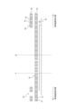
- Figure 2 is a diagram showing the configuration of the belt and reinforcing layer.
- the inner reinforcing layer 5a and the outer reinforcing layer 5b are shown arranged on the tire radial outside of the inclined belt layers 4a and 4b, but the strip width and number of strips of the inner strip member 52 and the outer strip member 54 are not accurate and have been simplified for the sake of convenience.
- the total number of reinforcement cords in one half in the tire width direction bounded by the tire equatorial plane CL, which is the inner side when mounted on a vehicle, is smaller than the total number of reinforcement cords in the other half in the tire width direction, which is the outer side when mounted on a vehicle.
- the number of reinforcement cords 51 of the inner reinforcement layer 5a in one half in the tire width direction is smaller than the number of reinforcement cords 51 of the inner reinforcement layer 5a in the other half in the tire width direction (outer side when mounted on a vehicle)
- the number of reinforcement cords 53 of the outer reinforcement layer 5b in one half in the tire width direction is smaller than the number of reinforcement cords 53 of the outer reinforcement layer 5b in the other half in the tire width direction (outer side when mounted on a vehicle).
- the inner reinforcement layer 5a is wound so that adjacent inner strip members 52 are wound without gaps in the outer half when mounted on the vehicle, while in the inner half when mounted on the vehicle, the inner strip members 52 are wound so that one or more gaps (in the illustrated example, a gap smaller than the width of the inner strip member 52) are formed between the inner strip members 52 near the tire equatorial plane CL, and adjacent inner strip members 52 are wound without gaps at the end side, and the reinforcement cords 51 are sparse by the amount of the gaps, so that the number of reinforcement cords of the inner reinforcement layer in one half in the tire width direction (inner side when mounted on the vehicle) is smaller than the number of reinforcement cords of the inner reinforcement layer in the other half in the tire width direction (outer side when mounted on the vehicle).
- the number of gaps is three, but this is illustrative and schematic, and the number and position of the gaps, the width of the gaps, etc. can be adjusted as appropriate.
- the outer reinforcement layer 5b is wound so that adjacent outer strip members 54 are wound without gaps in the outer half when the tire is mounted on the vehicle (meaning the gaps within each layer of the pair of layers; the gaps between the layer layers are not taken into consideration here, since they are areas where no strip members exist originally), while the outer strips 54 are wound so that one or more gaps (one outer strip 54 in the illustrated example) are formed between the inner half when the tire is mounted on the vehicle, and the reinforcement cords 53 are sparse by the gaps, so that the number of reinforcement cords of the outer reinforcement layer in one half in the tire width direction (inner side when mounted on the vehicle) is smaller than the number of reinforcement cords of the outer reinforcement layer in the other half in the tire width direction (outer side when mounted on the vehicle).
- the number of gaps is one, but this is illustrative and schematic, and the number and position of the gaps, the width of the gaps, etc. can be adjusted as appropriate.
- the end count of the reinforcing cord 51 of the inner reinforcing layer 5a in one half in the tire width direction is greater than the end count of the reinforcing cord 53 of the outer reinforcing layer 5b in one half in the tire width direction.
- an inner layer reinforcing layer 5a is arranged on the radially outer side of the belt 4, in which an inner strip member 52 made of a rubberized layer of one or more reinforcing cords 51 is wound in the circumferential direction of the tire, and an outer layer reinforcing layer 5b is arranged on the radially outer side of the inner layer reinforcing layer 5a, in which an outer strip member 54 made of a rubberized layer of one or more reinforcing cords 53 is wound in the circumferential direction of the tire. Therefore, radial growth of the tire during high-speed driving can be suppressed, and handling stability during high-speed driving can be improved.
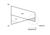
- FIG. 3A is a schematic diagram for explaining the deterioration of the ground contact shape
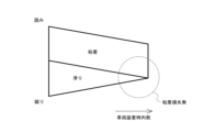
- Fig. 3B is a schematic diagram for explaining the improvement of the ground contact shape according to this embodiment.
- the cornering performance is deteriorated due to the loss of grip force caused by the increase in the area of the slipping area of the ground contact surface (schematically shown in the sparse dot area at the bottom left of Fig. 3A) and the loss of grip force caused by the decrease in the adhesive area (schematically shown in the dense dot area at the bottom right of Fig. 3A) caused by the deterioration of the ground contact shape.
- the total number of end pieces of the reinforcing cords in one half in the tire width direction bounded by the tire equatorial plane CL, which is the inner side when mounted on a vehicle, is smaller than the total number of end pieces of the reinforcing cords in the other half in the tire width direction, which is the outer side when mounted on a vehicle.
- the circumferential rigidity on the inner side when mounted on the vehicle which has a smaller contact length compared to the outer side when mounted on the vehicle, is appropriately reduced, thereby increasing the contact length on the inner side when mounted on the vehicle, and as shown diagrammatically in Figure 3B, the contact shape is improved, the area of the slippery region is reduced, and the area of the adhesive region is increased, thereby improving grip and cornering performance.
- the pneumatic tire of the present embodiment can achieve both steering stability during high-speed driving and cornering performance.
- the number of ends of the reinforcement cords 51 of the inner reinforcement layer 5a in one half in the tire width direction is smaller than the number of ends of the reinforcement cords 51 of the inner reinforcement layer 5a in the other half in the tire width direction (outer side when mounted on a vehicle), and that the number of ends of the reinforcement cords 53 of the outer reinforcement layer 5b in one half in the tire width direction (inner side when mounted on a vehicle) is smaller than the number of ends of the reinforcement cords 54 of the outer reinforcement layer 5b in the other half in the tire width direction (outer side when mounted on a vehicle).
- tire width direction position P as the tire width direction reference position, in one half of the inner reinforcing layer 5a in the tire width direction (inner side when mounted on a vehicle), the number of stitches of the reinforcement cord 51 on the outer side in the tire width direction of the tire width direction reference position P is greater than the number of stitches of the reinforcement cord 51 on the inner side in the tire width direction of the tire width direction reference position P.
- the tire width direction reference position exists in one half in the tire width direction such that the end count of the reinforcing cord on the outer side in the tire width direction of the tire width direction reference position is greater than the end count of the reinforcing cord on the inner side in the tire width direction of the tire width direction reference position. It is further preferable that no gap exists in the region on the outer side in the tire width direction of the tire width direction of the tire width direction reference position (up to the outer end in the tire width direction of the reinforcing layer 5).
- the tire width direction reference position has a tire width direction reference position such that the number of ends of the reinforcement cord 53 on the tire width direction outer side of the tire width direction reference position P is greater than the number of ends of the reinforcement cord 53 on the tire width direction inner side of the tire width direction reference position P.
- the outer reinforcing layer 5b can be configured such that the number of ends of the reinforcement cord 53 on the tire width direction outer side of the tire width direction reference position P is greater than the number of ends of the reinforcement cord 53 on the tire width direction inner side of the tire width direction reference position P in one half in the tire width direction of the outer reinforcing layer 5b (inner side when mounted on a vehicle).
- the number of ends of the reinforcement cords 51 of the inner reinforcement layer 5a in one half in the tire width direction is greater than the number of ends of the reinforcement cords 53 of the outer reinforcement layer 5b in one half in the tire width direction. This is because by relatively increasing the number of ends of the reinforcement cords 51 of the inner reinforcement layer 5a close to the inclined belt layers 4a, 4b, pantograph deformation can be more effectively suppressed.
- the inner strip member 52 and the outer strip member 54 are made of a rubberized layer of one or more reinforcing cords (two in the example of FIG. 2). It is preferable that the inner strip member 52 and/or the outer strip member 54 are made of a rubberized layer of two or less reinforcing cords, and in particular only one reinforcing cord. This is because the inner strip member 52 and/or the outer strip member 54 can be wound at an angle closer to 0°.
- the inner reinforcing layer 5a and the outer reinforcing layer 5b has a gap region in one half in the tire width direction (the inner side when mounted on a vehicle) where no strip members are present. This is because the absence of strip members is most effective in increasing the contact length on the inner side when mounted on a vehicle. From the perspective of the effect of increasing the contact length on the inner side when mounted on a vehicle, the width of the gap region in the tire width direction is preferably 10 strip members or more, more preferably 20 strip members or more, and even more preferably 30 strip members or more.
- At least one of the inner strip member 52 and the outer strip member 54 is present at least at the tire width direction position of the tire width direction end of the belt 4. This is because it is possible to improve the durability of the belt end position by preventing distortion from concentrating. From the viewpoint of obtaining this effect more reliably and further improving the durability of the belt end position, it is preferable that both the inner strip member 52 and the outer strip member 54 are present at least at the tire width direction position of the tire width direction end of the belt 4.
- the total number of reinforcing cords in one half in the tire width direction is preferably 0.25 to 0.6 times the total number of reinforcing cords in the other half in the tire width direction (outer side when mounted on a vehicle).
- the total number of reinforcing cords in one half in the tire width direction is preferably 0.25 to 0.6 times the total number of reinforcing cords in the other half in the tire width direction (outer side when mounted on a vehicle).
- the total number of reinforcing cords in one half in the tire width direction is 0.3 to 0.45 times the total number of reinforcing cords in the other half in the tire width direction (outer side when mounted on a vehicle).
- the number of stitches can be adjusted, for example, by winding the strip members so that there is a gap between them when viewed in cross section in the tire width direction. In other words, the larger the gap, the smaller the number of stitches.
- This adjustment method is particularly preferable when the inner strip member 52 and the outer strip member 54 are made of a rubberized layer of only one reinforcing cord 51, 53.
- Other examples include increasing or decreasing the number of reinforcing cords in the strip members (for the same strip width and the same gap arrangement, the greater the number of reinforcing cords, the greater the number of stitches), and adjusting the width of the strip members (for the same number of reinforcing cords and the same gap arrangement, the greater the width of the strip members, the smaller the number of stitches).
- the tire 1 may further have one or more reinforcing belt layers made of a rubberized layer of reinforcing cords on the tire radial outside of the outer reinforcing layer 5b.
- the reinforcing cords of the reinforcing belt layer may extend substantially in the tire width direction.
- the number of ends of the reinforcement cords 51 of the inner reinforcement layer 5a in one half in the tire width direction is smaller than the number of ends of the reinforcement cords 51 of the inner reinforcement layer 5a in the other half in the tire width direction
- the number of ends of the reinforcement cords 53 of the outer reinforcement layer 5b in one half in the tire width direction is smaller than the number of ends of the reinforcement cords 53 of the outer reinforcement layer 5b in the other half in the tire width direction.
- the total number of ends of the reinforcement cords in one half in the tire width direction bounded by the tire equatorial plane CL, which is the inner side when mounted on a vehicle is smaller than the total number of ends of the reinforcement cords in the other half in the tire width direction, which is the outer side when mounted on a vehicle, and it is also possible to configure only one of the inner reinforcement layer 5a and the outer reinforcement layer 5b so that the number of ends of the reinforcement cords in one half in the tire width direction is smaller than the number of ends of the reinforcement cords in the other half in the tire width direction (the other reinforcement layer is larger).
- the two reinforcing layers are a cap layer and a layer layer, but this is not limited to the example.
- both the inner reinforcing layer 5a and the outer reinforcing layer 5b may be cap layers.
- the number of ends of the reinforcement cord 51 of the inner reinforcement layer 5a in one half of the tire width direction is greater than the number of ends of the reinforcement cord 53 of the outer reinforcement layer 5b in one half of the tire width direction.
- the number of ends of the reinforcement cord 51 of the inner reinforcement layer 5a in one half of the tire width direction may be the same as the number of ends of the reinforcement cord 53 of the outer reinforcement layer 5b in one half of the tire width direction, or may be smaller than the number of ends of the reinforcement cord 53 of the outer reinforcement layer 5b in one half of the tire width direction.
Landscapes
- Engineering & Computer Science (AREA)
- Mechanical Engineering (AREA)
- Tires In General (AREA)
Abstract
車両装着時内側となるタイヤ赤道面を境界とするタイヤ幅方向の一方の半部における補強コードの打ち込み数の総数が、車両装着時外側となるタイヤ幅方向他方の半部における補強コードの打ち込み数の総数よりも小さい。
Description
本発明は、空気入りタイヤに関するものである。
従来、高速走行時に発生する遠心力による空気入りタイヤの径成長を抑制し、高速走行時における操縦安定性を向上させる技術が知られている(例えば、特許文献1)。
しかしながら、特許文献1に記載のような空気入りタイヤでは、特に旋回時において、接地形状の悪化により旋回性能が低下してしまうという問題があった。
そこで、本発明は、高速走行時の操縦安定性と、旋回性能とを両立させた、空気入りタイヤを提供することを目的とする。
本発明の要旨構成は、以下の通りである。
(1)ベルトコードのゴム引き層からなる1層以上のベルト層からなるベルトと、
前記ベルトのタイヤ径方向外側に配置された補強層と、を備えた、空気入りタイヤであって、
前記補強層は、1本以上の補強コードのゴム引き層からなる内側ストリップ部材をタイヤ周方向に巻回した状態の内層補強層と、前記内層補強層のタイヤ径方向外側に配置され、1本以上の補強コードのゴム引き層からなる外側ストリップ部材をタイヤ周方向に巻回した状態の外層補強層と、からなり、
車両装着時内側となるタイヤ赤道面を境界とするタイヤ幅方向の一方の半部における前記補強コードの打ち込み数の総数が、車両装着時外側となるタイヤ幅方向他方の半部における前記補強コードの打ち込み数の総数よりも小さいことを特徴とする、空気入りタイヤ。
ここで、「前記補強コードの打ち込み数の総数」とは、前記内層補強層の補強コードの打ち込み数と、前記外層補強層の補強コードの打ち込み数との和をいう。
本発明によれば、高速走行時の操縦安定性と、旋回性能とを両立させた、空気入りタイヤを提供することができる。
以下、本発明の実施形態について、図面を参照して詳細に例示説明する。
図1は、本発明の一実施形態にかかる空気入りタイヤのタイヤ幅方向断面図である。図1では、タイヤ赤道面CLを境界とするタイヤ幅方向の一方の半部のみを示している。当該タイヤ幅方向の一方の半部は、車両装着時内側となる。なお、本例では、図示しないタイヤ幅方向の他方の半部についても、後述の補強層の構成を除いては、タイヤ幅方向の一方の半部と同様の構成である。
図1に示すように、本実施形態の空気入りタイヤ(以下、単に「タイヤ」とも称する)1は、一対のビード部2と、一対のビード部間にトロイダル状に跨るカーカス3と、カーカス3のクラウン部のタイヤ径方向外側に配置されたベルト4と、ベルト4のタイヤ径方向外側に配置された補強層5と、を備えている。
図1に示すように、一対のビード部2の各々には、ビードコア2aが埋設されており、ビードコア2aのタイヤ径方向外側には、断面三角形状のビードフィラ2bが配置されている。
本例では、カーカス3は、有機繊維コードのゴム引き層からなる、2枚のカーカスプライ3a、3bからなる。クラウン部においてタイヤ内周側に位置するカーカスプライ3aは、一対のビード部2間をトロイダル状に跨るカーカス本体部3a1と、カーカス本体部3a1から延びてビードコア2a周りに折り返されてなるカーカス折り返し部3a2と、からなり、カーカス折り返し部3a2の端3a3は、図示例では、2層の傾斜ベルト層4a、4bの端のいずれよりもタイヤ幅方向内側に位置する。これにより、サイドウォール部の剛性を高めることができる。また、クラウン部においてタイヤ外周側に位置するカーカスプライ3bは、一対のビード部2間をトロイダル状に跨るカーカス本体部3b1と、カーカス本体部3b1から延びてビードコア2a周りに折り返されてなるカーカス折り返し部3b2と、からなり、カーカス折り返し部3b2の端3b3は、図示例では、ビードフィラ2bのタイヤ径方向外側端よりもタイヤ径方向内側に位置する。カーカスプライの枚数や端の位置は、図示の例には限定されず、様々な構成とすることができる。
本例では、ベルト4は、ベルトコードのゴム引き層からなる、2層の傾斜ベルト層4a、4bからなる。図示例では、タイヤ径方向内側に位置する傾斜ベルト層4aのタイヤ幅方向の幅は、タイヤ径方向外側に位置する傾斜ベルト層4bのタイヤ幅方向の幅よりも大きい。傾斜ベルト層4aのベルトコードのタイヤ周方向に対する傾斜角度は、特には限定されないが、例えば15~25°とすることができ、傾斜ベルト層4bのベルトコードのタイヤ周方向に対する傾斜角度は、特には限定されないが、例えば53°以上とすることができる。ベルトコードには、スチールコードを用いることができる。ベルト構造は、この例には限定されず、傾斜ベルト層の層数、タイヤ幅方向の幅、ベルトコードの材質やタイヤ周方向に対する傾斜角度は、様々なものとすることができる。
補強層5は、1本以上の補強コード51のゴム引き層からなる内側ストリップ部材52をタイヤ周方向に巻回した状態の内層補強層5aと、内層補強層5aのタイヤ径方向外側に配置され、1本以上の補強コード53のゴム引き層からなる外側ストリップ部材54をタイヤ周方向に巻回した状態の外層補強層5bと、からなる。
図示例では、内層補強層5aは、いわゆるキャップ層である。内層補強層5aは、タイヤ幅方向に連続して延び、内層補強層5aのタイヤ幅方向の幅は、傾斜ベルト層4a、4bのタイヤ幅方向の幅よりも大きく、従って、内層補強層5aは、傾斜ベルト層4a、4bのタイヤ幅方向の端を覆っている。内層補強層5aの補強コードは、有機繊維コードとすることができる。
図示例では、外層補強層5bは、いわゆるレイヤー層である。一対の外層補強層5bは、傾斜ベルト層4a、4bのタイヤ幅方向の端付近のみに延在し、傾斜ベルト層4a、4bのタイヤ幅方向の端を覆うように構成されている。外層補強層5bの補強コードは、有機繊維コードとすることができる。
図2は、ベルト及び補強層の構成を模式的に示す図である。図2では、傾斜ベルト層4a、4bのタイヤ径方向外側に、内層補強層5a及び外層補強層5bが配置された様子を模式的に示しているが、内側ストリップ部材52や外側ストリップ部材54のストリップ幅やストリップ数等は正確なものではなく説明の便宜上、簡単化している。
図2に示すように、本実施形態のタイヤでは、車両装着時内側となるタイヤ赤道面CLを境界とするタイヤ幅方向の一方の半部における補強コードの打ち込み数の総数は、車両装着時外側となるタイヤ幅方向他方の半部における補強コードの打ち込み数の総数よりも小さい。本例では、内層補強層5aに関し、タイヤ幅方向の一方の半部(車両装着時内側)における内層補強層5aの補強コード51の打ち込み数が、タイヤ幅方向の他方の半部(車両装着時外側)における内層補強層5aの補強コード51の打ち込み数よりも小さく、且つ、外層補強層5bに関し、タイヤ幅方向の一方の半部(車両装着時内側)における外層補強層5bの補強コード53の打ち込み数が、タイヤ幅方向の他方の半部(車両装着時外側)における外層補強層5bの補強コード53の打ち込み数よりも小さい。
図示例では、内層補強層5aに関し、車両装着時外側の半部では隣接する内側ストリップ部材52同士が、隙間なく巻回された状態であり、一方で、車両装着時内側の半部では、タイヤ赤道面CLに近くでは、内側ストリップ部材52間に1つ以上の隙間(図示例では、内側ストリップ部材52の幅よりも小さい隙間)を形成するようにして巻回され、端部側では隣接する内側ストリップ部材52同士が隙間なく巻回された状態であり、隙間の分だけ補強コード51が疎になり、これにより、上記のようにタイヤ幅方向の一方の半部(車両装着時内側)における内層補強層の補強コードの打ち込み数が、タイヤ幅方向の他方の半部(車両装着時外側)における内層補強層の補強コードの打ち込み数よりも小さくなっている。なお、図示例では、隙間の数は3つであるが、これは例示的且つ模式的なものであり、隙間の数や位置、隙間の幅等は、適宜調整することができる。
また、図示例では、外層補強層5bに関し、車両装着時外側の半部では隣接する外側ストリップ部材54同士が、隙間なく巻回された状態であり(一対のレイヤー層の各々のレイヤー層内の隙間のことを意味し、レイヤー層間は、元々ストリップ部材が存在しない領域であるため、ここでは考慮に入れていない)、一方で、車両装着時内側の半部では、外側ストリップ54間に1つ以上(図示例では外側ストリップ54の1つ分)の隙間を形成するようにして巻回された状態であり、隙間の分だけ補強コード53が疎になり、これにより、上記のようにタイヤ幅方向の一方の半部(車両装着時内側)における外層補強層の補強コードの打ち込み数が、タイヤ幅方向の他方の半部(車両装着時外側)における外層補強層の補強コードの打ち込み数よりも小さくなっている。なお、図示例では、隙間の数は1つであるが、これは例示的且つ模式的なものであり、隙間の数や位置、隙間の幅等は、適宜調整することができる。
図示例では、タイヤ幅方向の一方の半部における内層補強層5aの補強コード51の打ち込み数が、タイヤ幅方向の一方の半部における外層補強層5bの補強コード53の打ち込み数よりも大きい。
以下、本実施形態の空気入りタイヤの作用効果について説明する。
以下、本実施形態の空気入りタイヤの作用効果について説明する。
本実施形態の空気入りタイヤによれば、まず、ベルト4のタイヤ径方向外側に、1本以上の補強コード51のゴム引き層からなる内側ストリップ部材52をタイヤ周方向に巻回した状態の内層補強層5aと、内層補強層5aのタイヤ径方向外側に配置され、1本以上の補強コード53のゴム引き層からなる外側ストリップ部材54をタイヤ周方向に巻回した状態の外層補強層5bとが配置されているため、高速走行時のタイヤの径成長を抑制して、高速走行時の操縦安定性を高めることができる。
図3Aは、接地形状の悪化について説明するための模式図であり、図3Bは、本実施形態による接地形状の改善について説明するための模式図である。図3Aに模式的に示すように、特に旋回時においては、通常、接地形状の悪化により、接地面のうち滑り領域の面積の増大(図3Aの左下の疎なドットの領域で模式的に示している)によるグリップ力の損失と、粘着領域の減少(図3Aの右下の密なドットの領域で模式的に示している)によるグリップ力の損失とによって、旋回性能が低下してしまう問題があった。これに対し、本実施形態の空気入りタイヤでは、車両装着時内側となるタイヤ赤道面CLを境界とするタイヤ幅方向の一方の半部における補強コードの打ち込み数の総数は、車両装着時外側となるタイヤ幅方向他方の半部における補強コードの打ち込み数の総数よりも小さい。この構成によれば、特に車両旋回時に、車両装着時外側に比して接地長が小さくなる車両装着時内側の周方向剛性を適度に低下させて、車両装着時内側の接地長を増大させ、図3Bに模式的に示すように、接地形状を改善して、滑り領域の面積を減少させ、粘着領域の面積を増大させることで、グリップ力を向上させて旋回性能を向上させることができる。
以上のように、本実施形態の空気入りタイヤによれば、高速走行時の操縦安定性と、旋回性能とを両立させることができる。
本実施形態のように、内層補強層5aに関し、タイヤ幅方向の一方の半部(車両装着時内側)における内層補強層5aの補強コード51の打ち込み数が、タイヤ幅方向の他方の半部(車両装着時外側)における内層補強層5aの補強コード51の打ち込み数よりも小さく、且つ、外層補強層5bに関し、タイヤ幅方向の一方の半部(車両装着時内側)における外層補強層5bの補強コード53の打ち込み数が、タイヤ幅方向の他方の半部(車両装着時外側)における外層補強層5bの補強コード54の打ち込み数よりも小さいことが好ましい。内層補強層5aと外層補強層5bとの両方で、上記の効果を得て、旋回性能をより確実に向上させ得るからである。
図2を参照して、タイヤ幅方向位置Pをタイヤ幅方向基準位置として、内層補強層5aのタイヤ幅方向の一方の半部(車両装着時内側)において、タイヤ幅方向基準位置Pよりもタイヤ幅方向外側における補強コード51の打ち込み数が、タイヤ幅方向基準位置Pよりもタイヤ幅方向内側における補強コード51の打ち込み数よりも大きくなっている。
このように、内層補強層5a及び外層補強層5bのうちの少なくともいずれかにおいて、タイヤ幅方向の一方の半部において、タイヤ幅方向基準位置よりもタイヤ幅方向外側における補強コードの打ち込み数が、タイヤ幅方向基準位置よりもタイヤ幅方向内側における補強コードの打ち込み数よりも大きくなるような、前記タイヤ幅方向基準位置が存在することが好ましい。なお、前記タイヤ幅方向基準位置よりもタイヤ幅方向外側の領域には(補強層5のタイヤ幅方向外側端まで)隙間が存在しないことがさらに好ましい。
タイヤ赤道面CL側に近いほど、荷重の大きさにかかわらず接地するため、路面との接触頻度が高く、そのような個所において剛性を適度に緩和し、接地長を長くして、旋回時のみならず通常走行時においても接地形状を改善することができるからである。
上記の作用効果をより確実に得る観点からは、内層補強層5a及び外層補強層5bの両方において、タイヤ幅方向の一方の半部において、タイヤ幅方向基準位置よりもタイヤ幅方向外側における補強コードの打ち込み数が、タイヤ幅方向基準位置よりもタイヤ幅方向内側における補強コードの打ち込み数よりも大きくなるような、前記タイヤ幅方向基準位置が存在することがより好ましい。一方で、上記の例とは異なり、外層補強層5bのみについて、外層補強層5bのタイヤ幅方向の一方の半部(車両装着時内側)において、タイヤ幅方向基準位置Pよりもタイヤ幅方向外側における補強コード53の打ち込み数が、タイヤ幅方向基準位置Pよりもタイヤ幅方向内側における補強コード53の打ち込み数よりも大きくなるように構成することもできる。
本実施形態のように、タイヤ幅方向の一方の半部における内層補強層5aの補強コード51の打ち込み数が、タイヤ幅方向の一方の半部における外層補強層5bの補強コード53の打ち込み数よりも大きいことが好ましい。傾斜ベルト層4a、4bに近い内層補強層5aの補強コード51の打ち込み数を相対的に大きくすることで、パンタグラフ変形をより有効に抑えることができるからである。
内側ストリップ部材52、外側ストリップ部材54は、1本以上(図2の例では2本)の補強コードのゴム引き層からなっている。内側ストリップ部材52及び/又は外側ストリップ部材54は、2本以下、特に1本のみの補強コードのゴム引き層からなることが好ましい。より0°に近い角度で内側ストリップ52及び/又は外側ストリップ部材54を巻回することができるからである。
ここで、タイヤ幅方向の他方の半部(車両装着時外側)においては、内側ストリップ部材52間及び外側ストリップ部材54間に隙間が形成されていないことが好ましい。
車両装着時外側においては、剛性を高めて、接地長が伸びないようにして、車両装着時内側との接地長の差を縮めることで、接地形状を改善して、滑り領域の面積を減少させ、粘着領域の面積を増大させることで、グリップ力をさらに向上させて旋回性能をさらに向上させることができるからである。
車両装着時外側においては、剛性を高めて、接地長が伸びないようにして、車両装着時内側との接地長の差を縮めることで、接地形状を改善して、滑り領域の面積を減少させ、粘着領域の面積を増大させることで、グリップ力をさらに向上させて旋回性能をさらに向上させることができるからである。
一方で、タイヤ幅方向の他方の半部(車両装着時外側)においては、タイヤ赤道面CL付近にのみ内側ストリップ部材52間及び外側ストリップ部材54間の少なくともいずれかに隙間(特には限定されないが例えばストリップ部材5~15個分の隙間)を有し、他のタイヤ幅方向領では、内側ストリップ部材52間及び外側ストリップ部材54間に隙間が形成されていないことも好ましい。車両装着時内側と車両装着時外側との急激な剛性段差がタイヤ赤道面CL付近で生じないようにして、接地形状をさらに改善し得るからである。
内層補強層5a及び外層補強層5bのうちの少なくともいずれかは、タイヤ幅方向一方の半部(車両装着時内側)において、ストリップ部材が存在しないギャップ領域が存在することが好ましい。ストリップ部材が存在しない場合が最も、前記の車両装着時内側の接地長を増大させる効果が高いからである。車両装着時内側の接地長を増大させる効果の観点からは、ギャップ領域のタイヤ幅方向の幅は、ストリップ部材10個分以上とすることが好ましく、20個分以上とすることがより好ましく、30個分以上とすることがさらに好ましい。
少なくともベルト4のタイヤ幅方向端のタイヤ幅方向位置においては、内側ストリップ部材52及び外側ストリップ54部材の少なくともいずれかが存在することが好ましい。歪が集中しないようにしてベルト端位置の耐久性を向上させることができるからである。この効果をより確実に得てベルト端位置の耐久性をさらに向上させる観点からは、少なくともベルト4のタイヤ幅方向端のタイヤ幅方向位置においては、内側ストリップ部材52及び外側ストリップ54部材の両方が存在することが好ましい。
タイヤ幅方向の一方の半部(車両装着時内側)における補強コードの打ち込み数の総数は、タイヤ幅方向他方の半部(車両装着時外側)における補強コードの打ち込み数の総数の0.25~0.6倍であることが好ましい。0.6倍以下とすることにより、前記の車両装着時内側の接地長を増大させる効果をより確実なものにすることができ、一方で、0.25倍以上とすることにより、タイヤ幅方向の一方の半部(車両装着時内側)における剛性が低くなり過ぎないようにしてタイヤ耐久性を高めることができるからである。同様の理由により、タイヤ幅方向の一方の半部(車両装着時内側)における補強コードの打ち込み数の総数は、タイヤ幅方向他方の半部(車両装着時外側)における補強コードの打ち込み数の総数の0.3~0.45倍とすることがより好ましい。
上記打ち込み数は、例えば、タイヤ幅方向断面視においてストリップ部材間に隙間が設けられるように巻回することにより調整することができる。すなわち、隙間を大きく確保するほど、打ち込み数が小さくなる。内側ストリップ部材52や外側ストリップ部材54が1本のみの補強コード51、53のゴム引き層からなる場合には、特にこの調整方法とすることが好ましい。他にも例えば、ストリップ部材が有する補強コードの本数の増減(同じストリップ幅、同じ隙間の設け方であれば、補強コードの本数が大きい方が、打ち込み数が大きくなる)や、ストリップ部材の幅の調整(同じ補強コードの本数で、同じ隙間の設け方であれば、ストリップ部材の幅が大きい方が、打ち込み数は小さくなる)等を例示することができる。
以上、本発明の実施形態について説明したが、本発明は、上記の実施形態に何ら限定されるものではない。例えば、タイヤ1は、外層補強層5bのタイヤ径方向外側に、補強コードのゴム引き層からなる、1層以上の補強ベルト層をさらに有していても良い。当該補強ベルト層の補強コードは、略タイヤ幅方向に延びるものとすることができる。
また、上記の実施形態では、タイヤ幅方向の一方の半部における内層補強層5aの補強コード51の打ち込み数が、タイヤ幅方向の他方の半部における内層補強層5aの補強コード51の打ち込み数よりも小さく、且つ、タイヤ幅方向の一方の半部における外層補強層5bの補強コード53の打ち込み数が、タイヤ幅方向の他方の半部における外層補強層5bの補強コード53の打ち込み数よりも小さい例を示した。しかしながら、本発明では、車両装着時内側となるタイヤ赤道面CLを境界とするタイヤ幅方向の一方の半部における補強コードの打ち込み数の総数が、車両装着時外側となるタイヤ幅方向他方の半部における補強コードの打ち込み数の総数よりも小さければ良く、内層補強層5a及び外層補強層5bのうちのいずれか一方のみについて、タイヤ幅方向の一方の半部における補強コードの打ち込み数が、タイヤ幅方向の他方の半部における補強コードの打ち込み数よりも小さい(他方の補強層では大きい)構成とすることもできる。
また、上記の実施形態では、2層の補強層が、キャップ層とレイヤー層とである場合を示したが、この例には限定されず、例えば、内層補強層5a及び外層補強層5bのいずれもキャップ層としても良い。
また、上記の実施形態では、タイヤ幅方向の一方の半部における内層補強層5aの補強コード51の打ち込み数が、タイヤ幅方向の一方の半部における外層補強層5bの補強コード53の打ち込み数よりも大きい場合を示したが、タイヤ幅方向の一方の半部における内層補強層5aの補強コード51の打ち込み数が、タイヤ幅方向の一方の半部における外層補強層5bの補強コード53の打ち込み数と同じであるか、タイヤ幅方向の一方の半部における外層補強層5bの補強コード53の打ち込み数よりも小さくても良い。
1:空気入りタイヤ、 2:ビード部、
2a:ビードコア、 2b:ビードフィラ、
3:カーカス、
4:ベルト、 4a、4b:ベルト層、
5:補強層、 5a:内層補強層、 51:補強コード、
53:内側ストリップ部材、
5b:外層補強層、 52:補強コード、
54:外側ストリップ部材、
CL:タイヤ赤道面
2a:ビードコア、 2b:ビードフィラ、
3:カーカス、
4:ベルト、 4a、4b:ベルト層、
5:補強層、 5a:内層補強層、 51:補強コード、
53:内側ストリップ部材、
5b:外層補強層、 52:補強コード、
54:外側ストリップ部材、
CL:タイヤ赤道面
Claims (4)
- ベルトコードのゴム引き層からなる1層以上のベルト層からなるベルトと、
前記ベルトのタイヤ径方向外側に配置された補強層と、を備えた、空気入りタイヤであって、
前記補強層は、1本以上の補強コードのゴム引き層からなる内側ストリップ部材をタイヤ周方向に巻回した状態の内層補強層と、前記内層補強層のタイヤ径方向外側に配置され、1本以上の補強コードのゴム引き層からなる外側ストリップ部材をタイヤ周方向に巻回した状態の外層補強層と、からなり、
車両装着時内側となるタイヤ赤道面を境界とするタイヤ幅方向の一方の半部における前記補強コードの打ち込み数の総数が、車両装着時外側となるタイヤ幅方向他方の半部における前記補強コードの打ち込み数の総数よりも小さいことを特徴とする、空気入りタイヤ。 - 前記タイヤ幅方向の一方の半部における前記内層補強層の前記補強コードの打ち込み数が、前記タイヤ幅方向の他方の半部における前記内層補強層の前記補強コードの打ち込み数よりも小さく、且つ、
前記タイヤ幅方向の一方の半部における前記外層補強層の前記補強コードの打ち込み数が、前記タイヤ幅方向の他方の半部における前記外層補強層の前記補強コードの打ち込み数よりも小さい、請求項1に記載の空気入りタイヤ。 - 前記内層補強層及び前記外層補強層のうちの少なくともいずれかにおいて、前記タイヤ幅方向の一方の半部において、タイヤ幅方向基準位置よりもタイヤ幅方向外側における前記補強コードの打ち込み数が、前記タイヤ幅方向基準位置よりもタイヤ幅方向内側における前記補強コードの打ち込み数よりも大きくなるような、前記タイヤ幅方向基準位置が存在する、請求項1又は2に記載の空気入りタイヤ。
- 前記タイヤ幅方向の一方の半部における前記内層補強層の前記補強コードの打ち込み数が、前記タイヤ幅方向の一方の半部における前記外層補強層の前記補強コードの打ち込み数よりも大きい、請求項1又は2に記載の空気入りタイヤ。
Applications Claiming Priority (2)
| Application Number | Priority Date | Filing Date | Title |
|---|---|---|---|
| JP2023002618A JP2024098856A (ja) | 2023-01-11 | 2023-01-11 | 空気入りタイヤ |
| JP2023-002618 | 2023-01-11 |
Publications (1)
| Publication Number | Publication Date |
|---|---|
| WO2024150482A1 true WO2024150482A1 (ja) | 2024-07-18 |
Family
ID=91896776
Family Applications (1)
| Application Number | Title | Priority Date | Filing Date |
|---|---|---|---|
| PCT/JP2023/035969 Ceased WO2024150482A1 (ja) | 2023-01-11 | 2023-10-02 | 空気入りタイヤ |
Country Status (2)
| Country | Link |
|---|---|
| JP (1) | JP2024098856A (ja) |
| WO (1) | WO2024150482A1 (ja) |
Citations (5)
| Publication number | Priority date | Publication date | Assignee | Title |
|---|---|---|---|---|
| JP2002337510A (ja) * | 2001-05-18 | 2002-11-27 | Yokohama Rubber Co Ltd:The | 空気入りラジアルタイヤ |
| JP2014121979A (ja) * | 2012-12-21 | 2014-07-03 | Toyo Tire & Rubber Co Ltd | 空気入りタイヤ |
| JP2015074371A (ja) * | 2013-10-10 | 2015-04-20 | 東洋ゴム工業株式会社 | 空気入りタイヤ |
| JP2015101243A (ja) * | 2013-11-26 | 2015-06-04 | 東洋ゴム工業株式会社 | 空気入りタイヤ |
| JP2018167753A (ja) * | 2017-03-30 | 2018-11-01 | 横浜ゴム株式会社 | 空気入りタイヤ |
-
2023
- 2023-01-11 JP JP2023002618A patent/JP2024098856A/ja active Pending
- 2023-10-02 WO PCT/JP2023/035969 patent/WO2024150482A1/ja not_active Ceased
Patent Citations (5)
| Publication number | Priority date | Publication date | Assignee | Title |
|---|---|---|---|---|
| JP2002337510A (ja) * | 2001-05-18 | 2002-11-27 | Yokohama Rubber Co Ltd:The | 空気入りラジアルタイヤ |
| JP2014121979A (ja) * | 2012-12-21 | 2014-07-03 | Toyo Tire & Rubber Co Ltd | 空気入りタイヤ |
| JP2015074371A (ja) * | 2013-10-10 | 2015-04-20 | 東洋ゴム工業株式会社 | 空気入りタイヤ |
| JP2015101243A (ja) * | 2013-11-26 | 2015-06-04 | 東洋ゴム工業株式会社 | 空気入りタイヤ |
| JP2018167753A (ja) * | 2017-03-30 | 2018-11-01 | 横浜ゴム株式会社 | 空気入りタイヤ |
Also Published As
| Publication number | Publication date |
|---|---|
| JP2024098856A (ja) | 2024-07-24 |
Similar Documents
| Publication | Publication Date | Title |
|---|---|---|
| JP6214490B2 (ja) | 空気入りタイヤ | |
| JP4163244B1 (ja) | 空気入りタイヤ | |
| EP2196329B1 (en) | Pneumatic tire | |
| CN110712477B (zh) | 重载用充气轮胎 | |
| JP6445870B2 (ja) | 空気入りタイヤ | |
| US11305585B2 (en) | Pneumatic tire | |
| JP2023033469A (ja) | タイヤ | |
| JP7187852B2 (ja) | 空気入りタイヤ | |
| JP5277892B2 (ja) | 空気入りタイヤ | |
| KR102590070B1 (ko) | 공기 타이어 | |
| JP6450112B2 (ja) | 空気入りタイヤ | |
| JP2026012895A (ja) | タイヤ | |
| JP4257713B2 (ja) | 重荷重用空気入りラジアルタイヤ | |
| CN110520307B (zh) | 充气轮胎 | |
| JP2018086889A (ja) | 空気入りタイヤ | |
| JP2017193194A (ja) | 空気入りタイヤ | |
| CN110475678B (zh) | 充气轮胎 | |
| JP2024098856A (ja) | 空気入りタイヤ | |
| WO2016002538A1 (ja) | タイヤ | |
| JP4656961B2 (ja) | 空気入りタイヤ | |
| EP3900953B1 (en) | Tire | |
| JP6450111B2 (ja) | 空気入りタイヤ | |
| JP4652859B2 (ja) | 空気入りタイヤ | |
| JP4286588B2 (ja) | 空気入りタイヤ | |
| JP6825475B2 (ja) | 二輪自動車用タイヤ |
Legal Events
| Date | Code | Title | Description |
|---|---|---|---|
| 121 | Ep: the epo has been informed by wipo that ep was designated in this application |
Ref document number: 23916101 Country of ref document: EP Kind code of ref document: A1 |
|
| NENP | Non-entry into the national phase |
Ref country code: DE |
|
| 122 | Ep: pct application non-entry in european phase |
Ref document number: 23916101 Country of ref document: EP Kind code of ref document: A1 |