WO2024150437A1 - モジュラー・マルチレベル電力変換器 - Google Patents
モジュラー・マルチレベル電力変換器 Download PDFInfo
- Publication number
- WO2024150437A1 WO2024150437A1 PCT/JP2023/000883 JP2023000883W WO2024150437A1 WO 2024150437 A1 WO2024150437 A1 WO 2024150437A1 JP 2023000883 W JP2023000883 W JP 2023000883W WO 2024150437 A1 WO2024150437 A1 WO 2024150437A1
- Authority
- WO
- WIPO (PCT)
- Prior art keywords
- phase
- voltage
- current
- ref
- positive
- Prior art date
- Legal status (The legal status is an assumption and is not a legal conclusion. Google has not performed a legal analysis and makes no representation as to the accuracy of the status listed.)
- Ceased
Links
Images





Classifications
-
- H—ELECTRICITY
- H02—GENERATION; CONVERSION OR DISTRIBUTION OF ELECTRIC POWER
- H02M—APPARATUS FOR CONVERSION BETWEEN AC AND AC, BETWEEN AC AND DC, OR BETWEEN DC AND DC, AND FOR USE WITH MAINS OR SIMILAR POWER SUPPLY SYSTEMS; CONVERSION OF DC OR AC INPUT POWER INTO SURGE OUTPUT POWER; CONTROL OR REGULATION THEREOF
- H02M7/00—Conversion of AC power input into DC power output; Conversion of DC power input into AC power output
- H02M7/42—Conversion of DC power input into AC power output without possibility of reversal
- H02M7/44—Conversion of DC power input into AC power output without possibility of reversal by static converters
- H02M7/48—Conversion of DC power input into AC power output without possibility of reversal by static converters using discharge tubes with control electrode or semiconductor devices with control electrode
- H02M7/483—Converters with outputs that each can have more than two voltages levels
- H02M7/4835—Converters with outputs that each can have more than two voltages levels comprising two or more cells, each including a switchable capacitor, the capacitors having a nominal charge voltage which corresponds to a given fraction of the input voltage, and the capacitors being selectively connected in series to determine the instantaneous output voltage
-
- H—ELECTRICITY
- H02—GENERATION; CONVERSION OR DISTRIBUTION OF ELECTRIC POWER
- H02M—APPARATUS FOR CONVERSION BETWEEN AC AND AC, BETWEEN AC AND DC, OR BETWEEN DC AND DC, AND FOR USE WITH MAINS OR SIMILAR POWER SUPPLY SYSTEMS; CONVERSION OF DC OR AC INPUT POWER INTO SURGE OUTPUT POWER; CONTROL OR REGULATION THEREOF
- H02M7/00—Conversion of AC power input into DC power output; Conversion of DC power input into AC power output
- H02M7/42—Conversion of DC power input into AC power output without possibility of reversal
- H02M7/44—Conversion of DC power input into AC power output without possibility of reversal by static converters
- H02M7/48—Conversion of DC power input into AC power output without possibility of reversal by static converters using discharge tubes with control electrode or semiconductor devices with control electrode
- H02M7/483—Converters with outputs that each can have more than two voltages levels
- H02M7/4833—Capacitor voltage balancing
Definitions
- the present invention relates to a modular multilevel power converter (hereinafter, in this invention, referred to as an "MMC converter").
- MMC converter modular multilevel power converter
- the present invention relates to a modular multilevel power converter suitable for configuring a variable speed generator/motor device by connecting the DC sides of two MMC converters back-to-back to configure a frequency conversion device, and connecting the AC side of one MMC converter to a power system and the AC side of the other MMC converter to an AC rotating electric machine.
- the MMC converter circuit is made up of a unit converter that generates the required voltage by controlling the modulation rate of a PWM converter that uses an energy storage element with voltage source characteristics such as a capacitor as a voltage source.
- a capacitor is assumed to be the energy storage element, but this does not impair generality.
- the capacitor voltage of the unit converter fluctuates due to charging and discharging in a period determined by the AC frequency.
- Six two-terminal arms are provided in which these unit converters are connected in series, three of which are positive arms with their first terminals connected to each phase terminal of the AC power supply and their star-connected second terminals connected to the positive terminal of the DC power supply. The remaining three are negative arms with their second terminals connected to each phase terminal of the AC power supply and their star-connected first terminals connected to the negative terminal of the DC power supply.
- the current of an MMC converter can be divided into AC current and through current. Through current can be further divided into DC current and circulating current.
- AC current is split into two, flowing from each phase terminal of the AC power supply with an ungrounded neutral point to the positive arm and negative arm. AC current does not flow to the DC power supply side.
- DC current is split into three, flowing from the negative terminal of the DC power supply to the negative arm of each phase, passing through the positive arm of each phase and flowing to the positive terminal of the DC power supply.
- DC current does not flow to the AC power supply side. Circulating current passes from the negative arm through the positive arm, branches into the positive arms of the other two phases, and passes through the negative arm. Circulating current circulates inside the MMC converter without flowing to either the AC power supply side or the DC power supply side.
- the MMC converter circuit configured as above has five current degrees of freedom.
- the degrees of freedom of AC current when connected to an AC power source with an ungrounded neutral point or high resistance grounded neutral point is two.
- AC current can be decomposed into dq phases by three-phase to two-phase transformation (uvw/dq transformation).
- the degrees of freedom of through current are three.
- Through current can be decomposed into circulating currents corresponding to ⁇ phases and DC currents corresponding to zero phase by three-phase to three-phase transformation including zero phase (uvw/ ⁇ 0 transformation).
- MMC converters are classified as semiconductor power converters that use power semiconductor elements. Compared to other power devices that are primarily made of metal conductors such as iron or copper, power semiconductor elements have stricter restrictions on their overcurrent tolerance. Inevitably, the highest priority is given to accelerating current control and it is necessary to suppress transient overcurrents.
- control devices for semiconductor power converters have a current control function (hereinafter referred to as “converter current control” in this invention) that adjusts AC and DC currents at high speed, and a function (hereinafter referred to as “host control device” in this invention) that calculates AC and DC current commands in response to external operation commands, and have a hierarchical structure that adjusts AC and DC currents in response to commands from the host control device.
- converter current control a current control function
- host control device function
- the first feature of an MMC converter control device is that it requires adjustment of circulating current in addition to conventional AC and DC current.
- the characteristics of the MMC converter are greatly influenced by which physical quantity is used and how the circulating current command value is calculated.
- the second feature of the control device for the MMC converter is that it needs to have the ability to adjust the AC current, DC current, and circulating current mentioned above while at the same time keeping the voltages of the 6 x K capacitors installed in the unit converter within a specified range.
- This function is achieved by a function that keeps the time average value of the capacitor voltage in balance between K unit converters by mutually adjusting the modulation rates of K PWM converters provided for each unit converter within the same arm (hereinafter referred to in this invention as "inter-stage balance control”); a function that keeps the instantaneous value of the average voltage of the 2 x K capacitors that make up the positive arm and negative arm of each phase in balance between each phase (hereinafter referred to in this invention as “inter-phase balance control”); and a function that keeps in balance the instantaneous difference voltage value between the average voltage of the K capacitors in the positive arm and the average voltage of the K capacitors in the negative arm (hereinafter referred to in this invention as "positive-negative balance control”).
- Patent Document 1 discloses a basic circuit configuration in which an inductive element such as a reactor is provided between the first terminal of the positive arm and the AC terminal, and between the second terminal of the negative arm and the AC terminal, in order to suppress shoot-through current in an MMC converter.
- an inductive element such as a reactor
- Patent Document 2 discloses the basic hierarchical structure of a control system consisting of a PWM modulator and converter current control provided for each unit converter of an MMC converter. It also discloses a method of adding a second harmonic circulating current command to a fundamental current command.
- Patent document 3 discloses a method for realizing a variable speed generator/motor device by connecting the AC side of one of two MMC converters, the DC side of which is connected back-to-back, to an AC rotating electric machine. It also discloses a damper start method for starting a synchronous machine with an MMC converter, which in principle has the drawback of being unable to output DC current.
- Patent document 4 discloses the configuration and functional block diagram of a host control device for two MMC converters with the DC sides connected back-to-back.
- Patent document 5 specifically and systematically discloses a control configuration suitable for maintaining phase-to-phase balance and positive-negative balance of the capacitor voltages of the unit converters that make up the MMC converter.
- Patent document 6 discloses a method for suppressing the maximum value of the capacitor voltage by controlling the second harmonic of the circulating current of an MMC converter, and suppressing the maximum value of the arm current by controlling the fourth harmonic.
- Patent No. 5189105 Patent No. 5197623 Patent No. 6243083 International Publication No. 2022/059211 Patent No. 6618823 Patent No. 5827924
- MMC converters have the disadvantage of being larger in volume per output capacity than conventional three-level converters. This is particularly problematic when applying them to applications with strict restrictions on installation area and volume, such as pumped storage power plants and offshore wind power plants, which are often installed underground.
- MMC converters become larger is due to the capacitors used as energy storage elements.
- the capacitors often account for more than half of the arm volume.
- the capacitors can be made smaller by reducing the stored energy, but this creates a bottleneck as increased voltage pulsation occurs due to charging and discharging at a cycle determined by the AC frequency.
- FIG. 13 shows the relationship between capacitor capacitance and voltage pulsation.
- the capacitor capacitance coefficient KC on the horizontal axis is a dimensionless number, which is the time constant [seconds] obtained by dividing the energy when all capacitors are charged at the rated voltage by the rated active power output of the MMC converter, unitized per one cycle of the AC frequency.
- the frequency of the AC system is F0
- the rated output (active power) of the MMC converter is P0
- each of the six arms that make up the MMC converter is a series connection of K unit converters.
- the vertical axis in FIG. 13 represents the voltage ripple rate r, the maximum value Vc_max, the average value Vc_ave, and the minimum value Vc_min of the capacitor voltage.
- the voltages Vc_max, Vc_ave, and Vc_min indicate values unitized by the capacitor rated voltage V0.
- the maximum voltage Vc_max is adjusted to be the capacitor rated voltage V0 in order to maximize the capacitor voltage utilization rate.
- Figure 13 shows the changes in the voltage ripple rate r, the average capacitor voltage Vc_ave, and the minimum capacitor voltage Vc_min after adjustment.
- the voltage ripple rate r is suppressed to about 5 to 8% by increasing the capacitance of the capacitor without shying away from making the device larger, control of the MMC converter becomes much easier.
- the device volume increases almost in proportion to the capacitance coefficient KC of the capacitor on the horizontal axis of Fig. 13, so the converter becomes incomparably larger than conventional three-level converters.
- the capacitor capacity is reduced, the rated DC voltage of the MMC converter will decrease in proportion to the capacitor average voltage Vc_ave, and the rated DC current will need to be increased in inverse proportion. This will result in an increase in the current capacity of the self-extinguishing elements and anti-parallel diodes that make up the unit converter. Furthermore, if the capacitor capacity is reduced, the balance of the capacitor voltages of the K unit converters that make up the arm will be easily disrupted, making it impossible to continue operation due to disturbances such as AC power supply voltage fluctuations caused by the spread of a grid fault. As mentioned above, there is a lower limit to capacitor capacity.
- the capacitor voltage ripple factor r of the MMC converter When comparing the dimensions and volume of an MMC converter with those of a conventional three-level converter, even when including incidental equipment such as a harmonic filter that is unnecessary in an MMC converter, in order to bring the dimensions and volume of the MMC converter closer to those of a conventional three-level converter, the capacitor voltage ripple factor r of the MMC converter must be allowed to be 10% or more. Alternatively, the above-mentioned capacitor capacitance coefficient KC must be set to be smaller than 3.
- the present invention is suitable for solving problems when a system fault spreads while realizing a reduction in size and weight of the MMC converter by adjusting the range shown by the arrow in FIG. 13, specifically, "the capacitor capacitance coefficient KC is 3 or less” or “the capacitor voltage ripple rate r is 10% or more".
- the objective of the present invention is to solve the above problems and combine the advantages of MMC converters, such as low loss, with their disadvantages, such as compact size and improved operational continuity in the event of an asymmetrical accident.
- a positive-negative balance control method is used to generate a second harmonic circulating current command value proportional to the multiplication result of two difference voltages between the average voltage of the positive arm and the average voltage of the negative arm of the capacitor of the unit converter that constitutes the MMC converter and the positive-phase voltage phase of the AC voltage, and the circulating current command value and the circulating current feedback value are converted from three-phase to two-phase with a phase twice the positive-phase voltage phase and compared, and proportional-integral control is performed to settle the circulating current feedback value to the circulating current command value, thereby quickly suppressing the imbalance of the capacitor voltage between the positive arm and the negative arm in the event of an asymmetrical accident, thereby providing an MMC converter that is suitable for continuing operation when a system accident spreads.
- the configuration of the MMC converter 1000 is shown in Figure 14.
- an example is shown in which the MMC converter 1000 is connected as an AC power source to an AC system 2 via a unit transformer 4.
- a reactor 1001 is provided between the AC terminals of each phase (UC, VC, WC), the first terminal (A) of the positive arms 7UP, 7VP, 7WP, and the second terminal (B) of the negative arms 7UN, 7VN, 7WN.
- Each positive arm 7P (7UP, 7VP, 7WP) and each negative arm 7N (7UN, 7VN, 7WN) is configured by connecting K half-bridge circuits (K is a natural number) in series that make up the unit converter.
- Current transformers 10 are provided between the first terminals (A) of the positive arms 7UP, 7VP, 7WP and the reactor 1001.
- Current transformers 10 are also provided between the second terminals (B) of the negative arms 7UN, 7VN, 7WN and the reactor 1001.
- These six current transformers 10 measure the arm currents (IP_U, IP_V, IP_W, IN_U, IN_V, IN_W).
- the converter current control device is divided into three control calculators: AC current control calculator 1002, DC current control calculator 1003, and capacitor balance control calculator 1004.
- the AC current control calculator 1002 compares the AC current commands (IP_ref, IQ_ref) after 3-phase to 2-phase conversion with the AC currents (I ⁇ , I ⁇ ) and performs AC current control (ACACR) to calculate the AC voltage commands (Vacu, Vacv, Vacw).
- the AC current commands (IP_ref, IQ_ref) are the outputs of the capacitor voltage regulator (AVcR) and the system voltage control (AVR), respectively.
- Patent Document 5 does not describe a method for adjusting (IQ_ref), but since the application of the present invention is a power generation facility, system voltage control (AVR) is assumed.
- the DC current control calculator 1003 calculates the DC voltage command (Vdc) from the DC current command (Idc_ref), the DC current correction command (Ic0_ref), the DC current (Idc), and the DC voltage command (Vdc_ref).
- the capacitor balance control calculator 1004 is divided into three controls: phase-to-phase balance control, positive-to-negative balance control, and circulating current control, and has a hierarchical structure.
- the command values for phase-to-phase balance control and positive-to-negative balance control are always 0, and they are a higher-level system that gives commands to circulating current control. Therefore, the characteristic frequency of positive-to-negative balance control needs to be kept low so as not to interfere with the circulating current control.
- Phase balance control is a calculation that maintains balance in the phase average voltages (Vcu, Vcv, Vcw) of the U, V, and W phases by proportional-integral control using the proportional-integral controller 1011 so that the phase average voltages (Vcu, Vcv, Vcw) of the U, V, and W phases are set to the total capacitor average voltage (Vc) of the six arms 7 (7UP, 7VP, 7WP, 7UN, 7VN, 7WN).
- the phase balance control also includes an output limiter 1005 for the total capacitor average voltage (Vc).
- the maximum limit value is set to, for example, 110% of the rated voltage value of the total capacitor average voltage (Vc)
- the minimum limit value is set to 90% of the rated voltage value of the total capacitor average voltage (Vc).
- proportional-integral control is performed by the proportional-integral controller 1012 to keep the arm average voltages (Vcup, Vcvp, Vcwp) of the positive arm 7P and the arm average voltages (Vcun, Vcvn, Vcwn) of the negative arm 7N of each of the U, V, and W phases in balance.
- phase-to-phase balancing control and the output of the positive/negative balancing control are added for each phase by adder 1007 to calculate the circulating current command values (Icu_ref, Icv_ref, Icw_ref).
- the circulating current command value is coordinate-converted by the ⁇ 0-axis coordinate converter 1008 and converted into a circulating current command (Ic ⁇ _ref, Ic ⁇ _ref) and a DC current correction command (Ic0_ref). The relationship between them is given by equation (2).
- the DC current correction command (Ic0_ref) is a correction command value of the DC current command (Idc_ref) which is the input to the DC current control calculator 1003, and when the total capacitor average voltage (Vc) deviates from the command value due to a system accident or the like, the DC current command (Idc_ref) is corrected with the correction command value (Ic0_ref) to maintain the operating state of the MMC converter.
- the circulating current control matches the circulating current command (Ic ⁇ _ref, Ic ⁇ _ref) with the circulating current (Ic ⁇ , Ic ⁇ ) to output a balanced voltage correction command (Vb ⁇ , Vb ⁇ ) to keep the capacitor voltage in balance.
- the balanced voltage correction command is converted from a two-phase command value (Vb ⁇ , Vb ⁇ ) to a three-phase command value (Vbu, Vbv, Vbw) by the ⁇ -axis coordinate inverse converter 1009.
- the relationship between the two-phase command value (Vb ⁇ , Vb ⁇ ) and the three-phase command value (Vbu, Vbv, Vbw) is given by equation (3).
- the AC voltage commands (Vacu, Vacv, Vacw), DC voltage command (Vdc), and balanced voltage correction commands (Vbu, Vbv, Vbw) are added by adder 1010 to calculate the converter voltage commands (Vu, Vv, Vw).
- the present invention aims to reduce the capacitor capacity of the unit converter, and targets MMC converters whose voltage ripple rate r exceeds 10%. At the same time, it aims to realize a control method that can continue stable operation even when disturbances on the AC system side occur, such as when a system fault spreads.
- FIGS. 7A and 7B show the operating conditions when the MMC converter 1000 is connected to the downstream end of a single-circuit transmission line, the most frequent single ground fault occurs, and an asymmetric fault accompanied by open-phase operation occurs in AC system 2.
- FIG. 7A shows an example in which a ground fault occurs in phase A of AC system 2.
- FIG. 7B is a time chart showing the control timing when the ground fault shown in FIG. 7A occurs.
- one MMC converter is connected to the AC system 2 via the unit transformer 4, and the other MMC converter has its AC side connected to an AC rotating electric machine instead of the unit transformer 4, to form a variable speed generator/motor.
- Figures 16 and 17 show the behavior of the configurations of Figures 14 and 15 when the AC grid fault in Figures 7A and 7B described above spreads.
- the behavior when the grid fault spreads differs depending on whether the system is in power generation or electric operation, but below we will compare the behavior during power generation operation (P_ref>0).
- the upper part of Figure 16 has a two-stage configuration, with the upper part showing waveforms of three phase voltage signals (V_AN, V_BN, V_CN) on the first terminal (AT, BT, CT) side of the unit transformer 4 unitized by the rated voltage of the unit transformer 4.
- the lower part shows waveforms of three AC current signals (IAC_U, IAC_V, IAC_W) on the second terminal (U, V, W) side of the unit transformer 4 unitized by the rated value of the MMC converter 1000.
- the lower part of Figure 16 has a three-stage configuration, and the upper part shows waveforms of two signals, the arm average voltage (Vcup) of the U-phase positive arm 7UP of the MMC converter 1000 and the arm average voltage (Vcun) of the negative arm 7UN, unitized by the rated capacitor voltage value V0 of the MMC converter 1000. Similarly, the middle part shows the V phase, and the lower part shows the W phase.
- Figure 17 shows the instantaneous maximum and minimum values of the six capacitor voltages that make up each arm.
- the first row shows the instantaneous maximum (Vcupmax) and minimum (Vcupmin) capacitor values of the U-phase positive arm 7UP of the MMC converter 1000.
- the above two signals are unitized by the rated voltage of the capacitor and displayed overlapping on the same vertical axis coordinate.
- the second row shows the U-phase negative arm 7UN, and the bottom row shows the W-phase negative arm 7WN.
- the converter voltage commands are commands that activate the control outputs of the AC voltage commands (Vacu, Vacv, Vacw), DC voltage commands (Vdc), and balance voltage correction commands (Vbu, Vbv, Vbw).
- the control output of the interstage balance control is added for each unit converter at the latter stage of the converter voltage commands (Vu, Vv, Vw).
- the integrator shares the DC output in the steady state, and high-speed positive/negative balance control can be realized by limiting the purpose of the circulating current control to positive/negative balance control.
- a second harmonic circulating current command value (Icu_ref, Icv_ref, Icw_ref) is generated that is proportional to the three multiplication results of the positive-negative voltage difference (Vcu_pn, Vcv_pn, Vcw_pn), the amplitude of the AC current command value (
- the reference signal for the AC frequency is generated by multiplying the positive-negative voltage difference (Vcu_pn, Vcv_pn, Vcw_pn), the amplitude of the AC current command value (
- the circulating current feedback value (Icu, Icv, Icw) are converted from 2-phase to 3-phase at twice the phase of the positive-sequence voltage ( ⁇ v) and compared, and proportional-integral control is performed to settle the circulating current feedback value (Icq_fB, Icd_fB) after the 3-phase to 2-phase conversion to the circulating current command value (Icq_ref, Icd_ref), and the positive-negative balance voltage correction command (Vuab, Vvab, Vwab) is calculated by inversely converting from 2-phase to 3-phase at twice the phase of the positive-sequence voltage ( ⁇ v).
- the reference signal for the AC frequency is provided with an output polarity determiner that determines whether the input AC current command value (Iu_ref, Iv_ref, Iw_ref) should be output as is or inverted depending on the polarity of the converter output command (P_com), and the second harmonic circulating current command value (Icu_ref, Ic_pn, Ic_pn) is proportional to the multiplication results of the average voltage of the capacitor of the positive arm 7P of each phase, the positive-negative difference voltage (Vcu_pn, Vcv_pn, Vcw_pn) of the negative arm 7N, and the calculation output (Iu_out, Iv_out, Iw_out) of the output polarity determiner.
- the circulating current command value (Icu_ref, Icv_ref, Icw_ref) and the circulating current feedback value (Icu, Icv, Icw) are converted from three-phase to two-phase at twice the phase of the positive-sequence voltage ( ⁇ v) and compared, proportional-integral control is performed to settle the circulating current feedback value (Icq_fB, Icd_fB) after the three-phase to two-phase conversion to the circulating current command value (Icq_ref, Icd_ref), and the positive-negative balanced voltage correction command (Vuab, Vvab, Vwab) is calculated by inversely converting from two phases to three phases at twice the phase of the positive-sequence voltage ( ⁇ v).
- the second harmonic circulating current command value is generated, and the positive-negative balance voltage correction command is calculated using proportional-integral control to maintain balance between the average capacitor voltage of the positive arm and the average capacitor voltage of the negative arm, quickly eliminating the imbalance in capacitor voltages during an asymmetrical fault. This has the effect of enabling continued operation when a grid fault spreads.
- the MMC converter of the present invention is capable of both miniaturizing the device and ensuring continued operation in the event of a system fault.
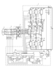
- FIG. 1 is a diagram showing a circuit configuration of a first embodiment of an MMC converter according to the present invention.
- FIG. 2 is a diagram showing the circuit configuration of the arms (positive arm and negative arm).
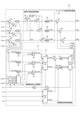
- FIG. 3 is a diagram showing a control block of the converter current control device of the MMC converter according to the first embodiment of the present invention.
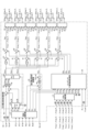
- FIG. 4 is a diagram showing a control block of the unit converter control device of the first embodiment of the MMC converter according to the present invention.
- FIG. 5 is a diagram showing a control block of a balance control calculator in the first embodiment of the MMC converter according to the present invention.
- FIG. 6 is a diagram showing a modification of the control block of the balance control calculator in the first embodiment of the MMC converter according to the present invention.
- FIG. 1 is a diagram showing a circuit configuration of a first embodiment of an MMC converter according to the present invention.
- FIG. 2 is a diagram showing the circuit configuration of the arms (positive arm and negative arm).
- FIG. 3 is a
- FIG. 7A is an explanatory diagram of a case where an asymmetrical fault occurs in the AC system during operation in the modular multilevel power conversion system of the present invention.
- FIG. 7B is a time chart showing a case where an asymmetrical fault occurs in the AC system during operation in the modular multilevel power conversion system of the present invention.
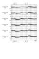
- FIG. 8 is a diagram showing waveforms when an asymmetrical fault occurs during power generation operation when the converter current control device of the present invention is used.
- FIG. 9 is a diagram showing waveforms when an asymmetrical fault occurs during power generation operation when the converter current control device of the present invention is used.
- FIG. 10 is a diagram showing a control block of a balance control calculator in the second embodiment of the MMC converter according to the present invention.
- FIG. 11 is a diagram showing a modified example of the configuration of the MMC converter according to the second embodiment of the present invention.
- FIG. 12 is a diagram showing a modified example of the converter current control device of the MMC converter according to the second embodiment of the present invention.
- FIG. 13 is a diagram showing the relationship between the capacitance of a capacitor constituting a unit converter of an MMC converter and the voltage ripple rate, maximum voltage value, average voltage value, and minimum voltage value of the capacitor.
- FIG. 14 is a diagram showing a circuit configuration of a conventional MMC converter.
- FIG. 15 is a diagram showing a converter control operation block diagram of a conventional MMC converter.
- FIG. 16 is a diagram showing waveforms when an asymmetrical fault occurs during power generation operation when a conventional converter current control device is used.
- FIG. 17 is a diagram showing waveforms when an asymmetrical fault occurs during power generation operation when a conventional converter current control device is used.
- FIG. 1 is a diagram showing the circuit configuration of a first embodiment of an MMC converter according to the present invention.
- MMC converter 1 is connected to AC system 2 via unit transformer 4, and signal transformer 5 consisting of three voltage transformers and three current transformers is provided between the first terminal (AT, BT, CT) of unit transformer 4 and AC system 2.
- DC power source 3 is connected to the DC side terminals (P, N) of MMC converter 1.
- the DC side terminals (P, N) of MMC converter 1 are grounded via high resistance 8 (8P, 8N) to fix the potential, and DC voltage (Vdc) is differentially measured by current transformer 9 (9P, 9N).
- Three-terminal reactors 6U, 6V, and 6W are provided between the AC terminals of each phase (U, V, W), the first terminals (A) of the positive arms 7UP, 7VP, and 7WP, and the second terminals (B) of the negative arms 7UN, 7VN, and 7WN.
- the AC terminals of each phase (U, V, W) are connected to the intermediate terminals (UC, VC, WC) of the three-terminal reactor 6 (6U, 6V, 6W), the first terminals (A) of the three positive arms 7UP, 7VP, and 7WP are connected to the positive terminals (UP, VP, WP) of the three-terminal reactor 6, and the second terminals (B) of the three negative arms 7UN, 7VN, and 7WN are connected to the negative terminals (UN, VN, WN) of the three-terminal reactor 6.
- Each arm of the positive arm 7P and the negative arm 7N is configured by connecting K half-bridge circuits that constitute a unit converter in series.
- Current transformers 10 are provided between the first terminals (A) of the positive arms 7UP, 7VP, 7WP and the positive terminals (UP, VP, WP) of the three-terminal reactor 6.
- current transformers 10 are provided between the second terminals (B) of the negative arms 7UN, 7VN, 7WN and the negative terminals (UN, VN, WN) of the three-terminal reactor 6.
- These six current transformers 10 measure the arm currents (IP_U, IP_V, IP_W, IN_U, IN_V, IN_W) and output them to the converter current control device 11.
- FIG. 2 shows the circuit configuration of arm 7 (positive arms 7UP, 7VP, 7WP, negative arms 7UN, 7VN, 7WN).
- the arm 7 is configured by connecting K half-bridge circuits 20 in series, which constitute a unit converter between the first terminal A and the second terminal B. Note that in FIG. 2, the circuit configuration is omitted except for the half-bridge circuit 20 "No. i".
- Half-bridge circuit 20 has two terminals, a positive terminal Y and a negative terminal X, and self-extinguishing elements 21H, 21L and anti-parallel diodes 22H, 22L that constitute a bidirectional chopper circuit are connected to capacitor 23.
- PWM control is performed based on commands from the converter current control device 11 so that the target voltage is output between the XY terminals in response to arc-on and arc-off commands from the gate drive units (GDU) 24H, 24L to the self-extinguishing elements 21H, 21L.
- GDU gate drive units
- a voltage detector that outputs the voltage of the capacitor 23 to the capacitor voltage detector 14 via a signal converter (CONV) 26.
- the arm output voltage (Varm) between the first terminal A and the second terminal B of the arm 7 in FIG. 2 is the sum of K unit output voltages (Varm_1 to varm_K) between the positive terminal Y and the negative terminal X of the half-bridge circuit 20.
- the 13 is an AC signal calculator that inputs the voltage and current signals from the signal transformer 5 to calculate and output reactive power (Q_fB) and positive-sequence voltage phase ( ⁇ v).
- the positive-sequence voltage phase ( ⁇ v) is output as a value converted to the second terminal side (U, V, W) according to the winding configuration of the unit transformer 4 and the phase sequence of the AC system 2.
- the output is advanced by 30 degrees from the detection phase of the first terminals (AT, BT, CT).
- capacitor voltage detector 14 is a capacitor voltage detector which inputs the capacitor voltages (vcup_1 to vcup_K, vcvp_1 to vcvp_K, vcwp_1 to vcwp_K, vcun_1 to vcun_K, vcvn_1 to vcvn_K, vcwn_1 to vcwn_K) of all unit converters (6 x K units) in the positive arm 7P and negative arm 7N, and calculates the average voltage (Vc) of all capacitors in the six arms 7.
- K is the number of unit converters connected in series in the arm 7.
- DC power detector 15 is a DC power detector that calculates DC power (Pdc) from the DC voltage (Vdc) and arm currents (IP_U, IP_V, IP_W, IN_U, IN_V, IN_W) using the following formula.
- Q_ref reactive power command
- Q_fB measured value
- Id_ref current command value
- Vc_ref capacitor voltage command
- Iq_ref current command value
- the power command limiter 19 corrects the DC current command (Idc_ref_org) by limiting it according to the positive-phase voltage amplitude (Vp_fB) and negative-phase voltage amplitude (Vn_fB) from the AC signal calculator 13, and outputs the corrected current command value (Idc_ref) to the converter current control device 11.
- FIG. 3 is a diagram showing the control block of the converter current control device 11 of the first embodiment of the MMC converter according to the present invention.
- the converter current control device 11 inputs the detected currents (IP_U, IP_V, IP_W, IN_U, IN_V, IN_W) of the current transformer 10, and the current calculator 27 calculates the AC currents (Iu, Iv, Iw), DC currents (Idc), and circulating currents (Icu, Icv, Icw) using the following equations.
- the AC current (Iq_fB, Id_fB) is the current after the AC current (Iu, Iv, Iw) is converted from three-phase to two-phase by the dq-axis coordinate converter 30.
- the relationship is given by equation (4).
- the AC voltage command (Vacq, Vacd) is converted from a two-phase command value (Vacq, Vacd) to a three-phase command value (Vacu, Vacv, Vacw) by the dq-axis coordinate inverse converter 38.
- the AC current control calculator 28 independently controls the first and second current degrees of freedom of the five current degrees of freedom of the MMC converter 1 on one side at high speed with zero steady-state deviation. Specifically, it configures two current control systems: a first proportional integral controller 44 that controls the active current component (q-axis) converted to the dq-axis coordinates by the positive-sequence voltage phase ( ⁇ v) of the fundamental wave, and a second proportional integral controller 45 that controls the reactive current component (d-axis).
- the DC current control calculator 29 is a DC current control calculator that calculates a DC voltage command (Vdc) by adding the output of matching the DC current command (Idc_ref) and the DC current (Idc) to the voltage command (Vdc_ref).
- the DC current control calculator 29 controls the third current degree of freedom of the five current degrees of freedom of the MMC converter 1 on one side at high speed with zero steady-state deviation, independent of the first and second current degrees of freedom. Specifically, it constitutes a current control system of a third proportional-integral controller 46 that controls the DC current component.
- the AC voltage commands (Vacu, Vacv, Vacw) and the DC voltage command (Vdc) are applied by an adder 56.
- the AC voltage commands (Vacu, Vacv, Vacw) are voltage command values for the AC voltage components of the arm output voltage (Varm) in FIG. 2.
- the AC voltage command given to the positive arm 7P is inverted and output, and the AC voltage command given to the negative arm 7N is output as is.
- 31 is an average calculator that inputs the instantaneous capacitor voltage values (Vcup_1 to Vcup_K, Vcvp_1 to Vcvp_K, Vcwp_1 to Vcwp_K, Vcun_1 to Vcun_K, Vcvn_1 to Vcvn_K, Vcwn_1 to Vcwn_K) of all unit converters (6 x K units) in the positive arm 7P and negative arm 7N, and calculates the arm average voltages (Vcup, Vcvp, Vcwp, Vcun, Vcvn, Vcwn) of arm 7 using the following formula.
- Vcup (Vcup_1+Vcup_2+...+Vcup_K)/K
- Vcvp (Vcvp_1+Vcvp_2+...+Vcwp_K)/K
- Vcun (Vcun_1+Vcun_2+...+Vcun_K)/K
- Vcvn (Vcvn_1+Vcvn_2+...+Vcvn_K)/K
- Vcwn (Vcwn_1+Vcwn_2+...+Vcwn_K)/K
- FIG. 4 shows the control block of the unit converter control device 33, and follows the configuration described in Patent Document 5.
- the unit converter control device 33 is composed of an inter-stage balance control calculator 58 and a PWM calculator 34.
- FIG. 4 will be explained using the example of the U-phase positive side arm 7UP, but the same applies to the other arms.
- the unit converter control device 33 is composed of K inter-stage balance control calculators 58 and K PWM calculators 34.
- the calculation method of the unit converter voltage command (Vup_1) given to the half-bridge circuit 20 in the first stage (No. 1) in Figure 2 will be explained as an example, omitting the dead time required for the self-extinguishing elements 21H and 21L for simplification. The same applies to the unit converter voltage commands given to the other half-bridge circuits 20.
- the differential voltage (Vcd_1) obtained by matching the capacitor average voltage (Vcup) and the instantaneous capacitor voltage value (Vcup_1) of the U-phase positive arm 7UP is input to the arm current polarity determiner 59.
- the output of the arm current polarity determiner 59 becomes the interstage balance correction command (Viup_1) for the interstage balance control.
- the above-mentioned inter-stage balance correction command (Viup_1) is generated as a U-phase positive arm voltage command (Vup/K) divided by the number K of half-bridge circuits. Furthermore, this output is divided by the instantaneous capacitor voltage value (Vcup_1) in divider 60 to calculate the unit converter voltage command (Vup_1).
- the PWM calculator 34 inputs the voltage command Vup_1 from the interstage balance control calculator 58, compares the peak value with a carrier wave (not shown), and when the voltage command Vup_1 is higher than the carrier wave, transmits a gate pulse GHup_1 to the gate drive unit 24H in FIG. 2 and outputs an ignition pulse to the gate of the self-extinguishing element 21H.
- the voltage command Vup_1 is lower than the carrier wave, transmits a gate pulse GLup_1 to the gate drive unit 24L in FIG. 2 and outputs an ignition pulse to the gate of the self-extinguishing element 21L.
- FIG. 5 is a diagram showing the control block of the capacitor balance control calculator 32 in the first embodiment of the MMC converter according to the present invention.
- the capacitor balance control calculator 32 calculates the phase average voltages (Vcu, Vcv, Vcw) and the total capacitor average voltage (Vc) from the arm average voltages (Vcup, Vcvp, Vcwp, Vcun, Vcvn, Vcwn) of arm 7 using the following equations.
- Vcu (1/2) ⁇ (Vcup+Vcun)
- Vcv (1/2) ⁇ (Vcvp+Vcvn)
- Vcw (1/2) ⁇ (Vcwp+Vcwn)
- Vc (1/3) ⁇ (Vcu+Vcv+Vcw)
- the capacitor balance control calculator 32 is divided into three parts: a phase-to-phase balance control calculator 35, a circulating current command calculator 36, and a circulating current control calculator 37.
- the circulating current control in this embodiment is used for positive-to-negative balance control that keeps the arm average voltages (Vcup, Vcvp, Vcwp) of the positive arm 7P and the arm average voltages (Vcun, Vcvn, Vcwn) of the negative arm 7N in balance.
- the phase balance control calculator 35 compares the total capacitor average voltage (Vc) with the phase average voltages of the U, V, and W phases (Vcu, Vcv, Vcw) and multiplies them by a proportional gain 49 (Kpb) to output phase balance voltage correction commands (Vupb, Vvpb, Vwpb).
- the phase balance control calculator 35 of the present invention is composed only of a proportional gain 49 (Kpb) to prevent interference with the circulating current control calculator 37, and does not include an integral gain.
- the positive-negative difference voltages (Vcu_pn, Vcv_pn, Vcw_pn) between the arm average voltages (Vcup, Vcvp, Vcwp) of the positive arm 7P and the arm average voltages (Vcun, Vcvn, Vcwn) of the negative arm 7N of each of the U, V, and W phases are calculated using the following formula.
- Vcu_pn Vcup-Vcun
- Vcv_pn Vcvp-Vcvn
- Vcw_pn Vcwp-Vcwn
- the circulating current command calculator 36 calculates the circulating current command values (Icu_ref, Icv_ref, Icw_ref) to keep the positive and negative differential voltages (Vcu_pn, Vcv_pn, Vcw_pn) at zero and maintain positive and negative balance.
- the U-phase circulating current command value (Icu_ref) is calculated and output by multiplying the differential voltage (Vcu_pn) between the arm average voltage (Vcup) of the U-phase positive arm 7UP and the arm average voltage (Vcun) of the negative arm 7UN by a proportional gain of 40 (Gain), and multiplying this by a phase voltage reference signal (cos ⁇ v) of the positive sequence voltage phase ( ⁇ v) calculated by a reference signal generator 65 in a multiplier 43.
- the V-phase and W-phase circulating current command values (Icv_ref, Icw_ref) are also calculated and output in a similar manner. The respective relationships are expressed by the following equations.
- Icu_ref Gain ⁇ Vcu_pn ⁇ cos( ⁇ v)
- Icv_ref Gain ⁇ Vcv_pn ⁇ cos ⁇ v ⁇ (2/3 ⁇ ) ⁇
- Icw_ref Gain ⁇ Vcw_pn ⁇ cos ⁇ v+(2/3 ⁇ ) ⁇
- the positive-negative voltage difference (Vcu_pn, Vcv_pn, Vcw_pn) is a waveform that contains a fundamental wave component, just like the positive-sequence voltage phase ( ⁇ v) of the AC voltage, so the circulating current command value (Icu_ref, Icv_ref, Icw_ref) multiplied by the three signals contains a second harmonic component.
- the second harmonic circulating current is coordinate-converted to a DC amount by a dq-axis coordinate converter, and the circulating current after coordinate conversion is set to the circulating current command value.
- the circulating current control calculator 37 uses the dq-axis coordinate converter 30 to convert the three-phase circulating current command values (Icu_ref, Icv_ref, Icw_ref) into two-phase circulating current command values (Icq_ref, Icd_ref).
- the dq-axis coordinate converter 64 also converts the three-phase circulating currents (Icu, Icv, Icw) into two-phase circulating currents (Icq_fB, Icd_fB).
- the positive-negative balance voltage correction command (Vcq_ref, Vcd_ref) is output by matching the above-mentioned circulating current command value (Icq_ref, Icd_ref) with the circulating current (Icq_fB, Icd_fB).
- the circulating current control calculator 37 controls the fourth and fifth current degrees of freedom of the five current degrees of freedom of the MMC converter 1 on one side at high speed with zero steady-state deviation, independent of the first to third current degrees of freedom.
- two current control systems are configured: a fourth proportional integral controller 47 that controls the circulating current component (q axis) transformed into dq axis coordinates with a positive-sequence voltage phase (2 ⁇ v) twice the fundamental wave, and a fifth proportional integral controller 48 that controls the circulating current (q axis).
- the positive/negative balance voltage correction command (Vcq_ref, Vcd_ref) is converted from two-phase command values (Vcq_ref, Vcd_ref) to three-phase command values (Vuab, Vvab, Vwab) by the dq-axis coordinate inverse converter 38.
- the relationship between the two-phase command values (Vcq_ref, Vcd_ref) and the three-phase command values (Vuab, Vvab, Vwab) is given by equation (6).
- phase-to-phase balanced voltage correction commands (Vupb, Vvpb, Vwpb) and the positive-negative balanced voltage correction commands (Vuab, Vvab, Vwab) are added by adders 39, and each adder 39 outputs a balanced voltage correction command (Vbu, Vbv, Vbw).
- the balanced voltage correction commands (Vbu, Vbv, Vbw) make it possible to maintain the voltage balance of the capacitor voltages between the phases and between the positive and negative terminals.
- the balanced voltage correction commands (Vbu, Vbv, Vbw) in this embodiment and the output from adder 56 in FIG. 3 are applied to adder 57 to become arm voltage commands (Vup, Vvp, Vwp, Vun, Vvn, Vwn) for arm 7.
- FIG. 6 is a diagram showing a modified example of the control block of the capacitor balance control calculator 32 in the first embodiment of the MMC converter according to the present invention.
- the circulating current command calculator 66 calculates the circulating current command values (Icu_ref, Icv_ref, Icw_ref) to maintain the positive-negative differential voltages (Vcu_pn, Vcv_pn, Vcw_pn) at zero and maintain positive-negative balance.
- the circulating current command value (Icu_ref) is calculated and output by multiplying the differential voltage (Vcu_pn) between the arm average voltage (Vcup) of the U-phase positive arm 7UP and the arm average voltage (Vcun) of the negative arm 7UN by a proportional gain 40 (Gain), and multiplying this by the amplitude (
- the V-phase and W-phase circulating current command values (Icv_ref, Icw_ref) are also calculated and output in a similar manner. The respective relationships are expressed by the following equations.
- Icu_ref Gain ⁇ Vcu_pn ⁇
- Icv_ref Gain ⁇ Vcv_pn ⁇
- Icw_ref Gain ⁇ Vcw_pn ⁇
- the positive-negative voltage difference (Vcu_pn, Vcv_pn, Vcw_pn) is a waveform that contains a fundamental wave component, just like the positive-sequence voltage phase ( ⁇ v) of the AC voltage, so the circulating current command value (Icu_ref, Icv_ref, Icw_ref) multiplied by the three signals contains a second harmonic component.
- the second harmonic circulating current is coordinate-converted to a DC amount by a dq-axis coordinate converter, and the circulating current after coordinate conversion is set to the circulating current command value.
- Proportional gain 40 is a gain for converting to circulating current command values (Icu_ref, Icv_ref, Icw_ref).
- the setting value of proportional gain 40 (Gain) suitable for balancing between positive and negative of an MMC converter with a capacitor voltage ripple rate r of 10% or more is set to, for example, 0.4 or more and 0.6 or less.
- this is the setting value when the amplitude (
- Figure 7A shows the operating conditions when the MMC converter is connected to the downstream end of a single-circuit transmission line, a single-line earth fault occurs, which is the most frequent occurrence, and an asymmetric fault accompanied by open-phase operation occurs in AC system 2.
- Figure 7B shows the explanation of the time chart when an asymmetric fault occurs in the AC system in Figure 7B.
- FIGS. 8 and 9 show the behavior of the configurations of FIG. 1, FIG. 3, and FIG. 6 of the first embodiment of the present invention when the AC system fault of FIG. 7 described above spreads.
- Figures 8 and 9 show the DC power (Pdc) and reactive power (Q_fB) of MMC converter 1 at rated operation, with the rated power factor being 0.95.
- the arm average voltage balance is maintained until time t1 before the accident occurs, and operation continues without increasing the voltage imbalance even between time t2 and time t5, when the leading end circuit breaker 52F and trailing end circuit breaker 52B are opened and an open-phase state (two-phase operation) occurs. Furthermore, even after time t5, when the trailing end circuit breaker 52B is reclosed, operation returns to the voltage balance state it was at time t1 before the accident occurred.
- the MMC converter 1 can continue to operate stably even during open-phase operation.
- Example 1 Furthermore, the configuration of Example 1 has the following two advantages:
- FIG. 10 is a diagram showing a capacitor balance control calculator 50 of a second embodiment of an MMC converter according to the present invention.
- the circuit configuration of the MMC converter and the control block diagram of the converter current control device are the same as those of the first embodiment shown in FIG. 1 and FIG. 3, and therefore their explanations are omitted to avoid duplication.
- the converter current control device constituting the MMC converter 1 of the second embodiment is configured by replacing the capacitor balance control calculator 32 of the converter current control device 11 of the first embodiment shown in FIG. 3 with the capacitor balance control calculator 50 shown in FIG. 10.
- the capacitor balance control calculator 50 in the second embodiment is divided into three parts: the interphase balance control calculator 35, the circulating current command calculator 51, and the circulating current control calculator 37.
- the configurations of the interphase balance control calculator 35 and the circulating current control calculator 37 are the same as those in the first embodiment, so a description thereof will be omitted.
- the method of calculating the circulating current command values (Icu_ref, Icv_ref, Icw_ref) in the circulating current command calculator 51 will be described.
- the AC current commands (Iq_ref, Id_ref) are converted to three-phase current command values (Iu_ref, Iv_ref, Iw_ref) by the dq-axis coordinate inverse converter 38.
- the three-phase current command values (Iu_ref, Iv_ref, Iw_ref) are input to the output polarity determiner 42.
- the output polarity determiner 42 inverts the sign of the input when the converter output command (P_com) of the MMC converter 1 is in power generation operation (P_com>0), and outputs the input as is when the converter is in electric power operation (P_ref ⁇ 0).
- the circulating current command values (Icu_ref, Icv_ref, Icw_ref) are obtained by multiplying the positive-negative differential voltage (Vcu_pn, Vcv_pn, Vcw_pn) by the proportional gain 54 (Gain) and multiplying it by the calculation output (Iu_out, Iv_out, Iw_out) from the output polarity determiner 42 using the multiplier 43.
- the circulating current command calculator 51 outputs the circulating current command values (Icu_ref, Icv_ref, Icw_ref) to the circulating current control calculator 37.
- the above relationship is expressed by the following equation.
- Icu_ref Gain ⁇ Vcu_pn ⁇ Iu_out
- Icv_ref Gain ⁇ Vcv_pn ⁇ Iv_out
- Icw_ref Gain ⁇ Vcw_pn ⁇ Iw_out
- the positive-negative differential voltage (Vcu_pn, Vcv_pn, Vcw_pn) is a waveform that contains a fundamental wave component, just like the calculation output (Iu_out, Iv_out, Iw_out) from the output polarity determiner 42, so the circulating current command value (Icu_ref, Icv_ref, Icw_ref) obtained by multiplying the two contains a second harmonic component.
- the circulating current of the second harmonic is coordinate-converted to a DC amount by the dq-axis coordinate converter 30, and the circulating current control calculator 37 is configured to settle the circulating current after coordinate conversion to the circulating current command value.
- the positive-sequence voltage phase ( ⁇ v) of the AC voltage used to calculate the circulating current command value in the first embodiment is not required, so the voltage balance of the capacitor voltage can be maintained with a simpler configuration, and the MMC converter can continue to operate stably even during open-phase operation.
- FIGS. 11 and 12 show modified examples of the second embodiment. Specifically, FIG. 11 shows a modified example of the MMC converter 1 shown in FIG. 1, and FIG. 12 shows a modified example of the converter current control device 11 constituting the MMC converter 1 shown in FIG. 1.
- the modified MMC converter 1a shown in FIG. 11 has a configuration in which the upper control device 12 and converter current control device 11 of the MMC converter 1 are replaced with an upper control device 53 and a converter current control device 52.
- the upper control device 53 constituting the MMC converter 1a in FIG. 11 has an interface for transmitting a DC power command (P_ref) to the converter current control device 52, and transmits the DC power command (P_ref) to the converter current control device 52.
- P_ref DC power command
- the modified converter current control device 52 shown in FIG. 12 uses the DC power command (P_ref) from the upper control device 53 in the output polarity determiner of the capacitor balance control calculation 54 instead of the converter output command (P_com) of the MMC converter 1.
- Figs. 11 and 12 show a modified example of the second embodiment
- the present invention can also be realized by combining a converter current control device 52 having an interface for transmitting and receiving a DC power command (P_ref), a higher-level control device 53, and the first embodiment.
- P_ref DC power command
Landscapes
- Engineering & Computer Science (AREA)
- Power Engineering (AREA)
- Inverter Devices (AREA)
Priority Applications (3)
| Application Number | Priority Date | Filing Date | Title |
|---|---|---|---|
| JP2024570005A JPWO2024150437A1 (https=) | 2023-01-13 | 2023-01-13 | |
| EP23916057.5A EP4651360A1 (en) | 2023-01-13 | 2023-01-13 | Modular multilevel power converter |
| PCT/JP2023/000883 WO2024150437A1 (ja) | 2023-01-13 | 2023-01-13 | モジュラー・マルチレベル電力変換器 |
Applications Claiming Priority (1)
| Application Number | Priority Date | Filing Date | Title |
|---|---|---|---|
| PCT/JP2023/000883 WO2024150437A1 (ja) | 2023-01-13 | 2023-01-13 | モジュラー・マルチレベル電力変換器 |
Publications (1)
| Publication Number | Publication Date |
|---|---|
| WO2024150437A1 true WO2024150437A1 (ja) | 2024-07-18 |
Family
ID=91896749
Family Applications (1)
| Application Number | Title | Priority Date | Filing Date |
|---|---|---|---|
| PCT/JP2023/000883 Ceased WO2024150437A1 (ja) | 2023-01-13 | 2023-01-13 | モジュラー・マルチレベル電力変換器 |
Country Status (3)
| Country | Link |
|---|---|
| EP (1) | EP4651360A1 (https=) |
| JP (1) | JPWO2024150437A1 (https=) |
| WO (1) | WO2024150437A1 (https=) |
Citations (7)
| Publication number | Priority date | Publication date | Assignee | Title |
|---|---|---|---|---|
| JP5189105B2 (ja) | 2006-12-08 | 2013-04-24 | シーメンス アクチエンゲゼルシヤフト | 電流変換装置 |
| JP5197623B2 (ja) | 2006-12-08 | 2013-05-15 | シーメンス アクチエンゲゼルシヤフト | エネルギー蓄積器が配分されたモジュール式コンバータ |
| JP5827924B2 (ja) | 2012-05-30 | 2015-12-02 | 株式会社日立製作所 | 電圧型電力変換装置の制御装置及び制御方法 |
| WO2016136682A1 (ja) * | 2015-02-25 | 2016-09-01 | 日立三菱水力株式会社 | 可変速発電電動装置および可変速発電電動システム |
| JP2017143626A (ja) * | 2016-02-09 | 2017-08-17 | 株式会社東芝 | 電力変換装置 |
| JP2021145436A (ja) * | 2020-03-11 | 2021-09-24 | 株式会社日立製作所 | 周波数変換器の制御装置ならびに制御方法、及び可変速揚水発電システムの制御装置 |
| WO2022059211A1 (ja) | 2020-09-18 | 2022-03-24 | 日立三菱水力株式会社 | モジュラー・マルチレベル電力変換器および可変速発電電動装置 |
Family Cites Families (4)
| Publication number | Priority date | Publication date | Assignee | Title |
|---|---|---|---|---|
| EP3905507A4 (en) * | 2018-12-25 | 2021-12-15 | Mitsubishi Electric Corporation | POWER CONVERSION DEVICE |
| WO2021048906A1 (ja) * | 2019-09-09 | 2021-03-18 | 三菱電機株式会社 | 電力変換装置 |
| JP7375553B2 (ja) * | 2020-01-06 | 2023-11-08 | 富士電機株式会社 | 電力変換装置 |
| JP2021185727A (ja) * | 2020-05-25 | 2021-12-09 | 株式会社日立製作所 | 電力変換装置の制御装置及び制御方法 |
-
2023
- 2023-01-13 WO PCT/JP2023/000883 patent/WO2024150437A1/ja not_active Ceased
- 2023-01-13 JP JP2024570005A patent/JPWO2024150437A1/ja active Pending
- 2023-01-13 EP EP23916057.5A patent/EP4651360A1/en active Pending
Patent Citations (9)
| Publication number | Priority date | Publication date | Assignee | Title |
|---|---|---|---|---|
| JP5189105B2 (ja) | 2006-12-08 | 2013-04-24 | シーメンス アクチエンゲゼルシヤフト | 電流変換装置 |
| JP5197623B2 (ja) | 2006-12-08 | 2013-05-15 | シーメンス アクチエンゲゼルシヤフト | エネルギー蓄積器が配分されたモジュール式コンバータ |
| JP5827924B2 (ja) | 2012-05-30 | 2015-12-02 | 株式会社日立製作所 | 電圧型電力変換装置の制御装置及び制御方法 |
| WO2016136682A1 (ja) * | 2015-02-25 | 2016-09-01 | 日立三菱水力株式会社 | 可変速発電電動装置および可変速発電電動システム |
| JP6243083B2 (ja) | 2015-02-25 | 2017-12-06 | 日立三菱水力株式会社 | 可変速発電電動装置および可変速発電電動システム |
| JP2017143626A (ja) * | 2016-02-09 | 2017-08-17 | 株式会社東芝 | 電力変換装置 |
| JP6618823B2 (ja) | 2016-02-09 | 2019-12-11 | 株式会社東芝 | 電力変換装置 |
| JP2021145436A (ja) * | 2020-03-11 | 2021-09-24 | 株式会社日立製作所 | 周波数変換器の制御装置ならびに制御方法、及び可変速揚水発電システムの制御装置 |
| WO2022059211A1 (ja) | 2020-09-18 | 2022-03-24 | 日立三菱水力株式会社 | モジュラー・マルチレベル電力変換器および可変速発電電動装置 |
Non-Patent Citations (1)
| Title |
|---|
| See also references of EP4651360A1 |
Also Published As
| Publication number | Publication date |
|---|---|
| EP4651360A1 (en) | 2025-11-19 |
| JPWO2024150437A1 (https=) | 2024-07-18 |
Similar Documents
| Publication | Publication Date | Title |
|---|---|---|
| JP5542609B2 (ja) | 無効電力補償装置 | |
| EP2437389B1 (en) | DC-link voltage balancing system and method for multilevel converters | |
| US10826378B2 (en) | Power conversion apparatus for interconnection with a three-phrase ac power supply | |
| KR101688649B1 (ko) | 중성점 전압의 불평형 제어에 의한 고효율 3 레벨 태양광 인버터 | |
| CN110112753B (zh) | 一种星形连接级联statcom相间直流电压均衡控制方法 | |
| US9755551B2 (en) | Power conversion device | |
| JP7375553B2 (ja) | 電力変換装置 | |
| JP7360559B2 (ja) | モジュラー・マルチレベル電力変換器および可変速発電電動装置 | |
| JP7383208B1 (ja) | 電力変換装置 | |
| Son et al. | Suppression of circulating current in parallel operation of three-level converters | |
| WO2019073761A1 (ja) | 電力変換装置 | |
| EP3836331A1 (en) | Power conversion device | |
| JP2017118635A (ja) | 自励式無効電力補償装置 | |
| JP2000060196A (ja) | 電力変換器の制御装置 | |
| CN120855552B (zh) | 自同步电压源组串式光伏逆变器系统及控制方法 | |
| Kumar et al. | Asymmetrical three-phase multilevel inverter for grid-integrated PLL-less system | |
| US12218577B2 (en) | Power conversion device and control device having overcurrent suppression | |
| Zhang et al. | Circulating current control scheme of modular multilevel converters supplying passive networks under unbalanced load conditions | |
| JP2019140743A (ja) | 電力変換装置 | |
| WO2024150437A1 (ja) | モジュラー・マルチレベル電力変換器 | |
| JP2017153277A (ja) | 自励式無効電力補償装置 | |
| US12355377B2 (en) | Adjustable speed generator motor system with full power converter | |
| US12355245B2 (en) | Reactive power compensation device | |
| JP3242814B2 (ja) | 電力系統の補償制御装置 | |
| JP7776040B1 (ja) | 制御装置、電力変換装置、制御方法 |
Legal Events
| Date | Code | Title | Description |
|---|---|---|---|
| 121 | Ep: the epo has been informed by wipo that ep was designated in this application |
Ref document number: 23916057 Country of ref document: EP Kind code of ref document: A1 |
|
| WWE | Wipo information: entry into national phase |
Ref document number: 2024570005 Country of ref document: JP |
|
| NENP | Non-entry into the national phase |
Ref country code: DE |
|
| WWP | Wipo information: published in national office |
Ref document number: 2023916057 Country of ref document: EP |