WO2024143000A1 - リチウム二次電池およびセパレータ - Google Patents
リチウム二次電池およびセパレータ Download PDFInfo
- Publication number
- WO2024143000A1 WO2024143000A1 PCT/JP2023/045070 JP2023045070W WO2024143000A1 WO 2024143000 A1 WO2024143000 A1 WO 2024143000A1 JP 2023045070 W JP2023045070 W JP 2023045070W WO 2024143000 A1 WO2024143000 A1 WO 2024143000A1
- Authority
- WO
- WIPO (PCT)
- Prior art keywords
- convex portion
- separator
- pattern
- negative electrode
- secondary battery
- Prior art date
- Legal status (The legal status is an assumption and is not a legal conclusion. Google has not performed a legal analysis and makes no representation as to the accuracy of the status listed.)
- Ceased
Links
Images




Classifications
-
- H—ELECTRICITY
- H01—ELECTRIC ELEMENTS
- H01M—PROCESSES OR MEANS, e.g. BATTERIES, FOR THE DIRECT CONVERSION OF CHEMICAL ENERGY INTO ELECTRICAL ENERGY
- H01M50/00—Constructional details or processes of manufacture of the non-active parts of electrochemical cells other than fuel cells, e.g. hybrid cells
- H01M50/40—Separators; Membranes; Diaphragms; Spacing elements inside cells
- H01M50/463—Separators, membranes or diaphragms characterised by their shape
- H01M50/469—Separators, membranes or diaphragms characterised by their shape tubular or cylindrical
-
- H—ELECTRICITY
- H01—ELECTRIC ELEMENTS
- H01M—PROCESSES OR MEANS, e.g. BATTERIES, FOR THE DIRECT CONVERSION OF CHEMICAL ENERGY INTO ELECTRICAL ENERGY
- H01M4/00—Electrodes
- H01M4/02—Electrodes composed of, or comprising, active material
- H01M4/13—Electrodes for accumulators with non-aqueous electrolyte, e.g. for lithium-accumulators; Processes of manufacture thereof
- H01M4/134—Electrodes based on metals, Si or alloys
-
- H—ELECTRICITY
- H01—ELECTRIC ELEMENTS
- H01M—PROCESSES OR MEANS, e.g. BATTERIES, FOR THE DIRECT CONVERSION OF CHEMICAL ENERGY INTO ELECTRICAL ENERGY
- H01M10/00—Secondary cells; Manufacture thereof
- H01M10/05—Accumulators with non-aqueous electrolyte
- H01M10/052—Li-accumulators
-
- H—ELECTRICITY
- H01—ELECTRIC ELEMENTS
- H01M—PROCESSES OR MEANS, e.g. BATTERIES, FOR THE DIRECT CONVERSION OF CHEMICAL ENERGY INTO ELECTRICAL ENERGY
- H01M10/00—Secondary cells; Manufacture thereof
- H01M10/05—Accumulators with non-aqueous electrolyte
- H01M10/058—Construction or manufacture
-
- H—ELECTRICITY
- H01—ELECTRIC ELEMENTS
- H01M—PROCESSES OR MEANS, e.g. BATTERIES, FOR THE DIRECT CONVERSION OF CHEMICAL ENERGY INTO ELECTRICAL ENERGY
- H01M10/00—Secondary cells; Manufacture thereof
- H01M10/05—Accumulators with non-aqueous electrolyte
- H01M10/058—Construction or manufacture
- H01M10/0587—Construction or manufacture of accumulators having only wound construction elements, i.e. wound positive electrodes, wound negative electrodes and wound separators
-
- H—ELECTRICITY
- H01—ELECTRIC ELEMENTS
- H01M—PROCESSES OR MEANS, e.g. BATTERIES, FOR THE DIRECT CONVERSION OF CHEMICAL ENERGY INTO ELECTRICAL ENERGY
- H01M4/00—Electrodes
- H01M4/02—Electrodes composed of, or comprising, active material
- H01M4/36—Selection of substances as active materials, active masses, active liquids
- H01M4/38—Selection of substances as active materials, active masses, active liquids of elements or alloys
-
- H—ELECTRICITY
- H01—ELECTRIC ELEMENTS
- H01M—PROCESSES OR MEANS, e.g. BATTERIES, FOR THE DIRECT CONVERSION OF CHEMICAL ENERGY INTO ELECTRICAL ENERGY
- H01M50/00—Constructional details or processes of manufacture of the non-active parts of electrochemical cells other than fuel cells, e.g. hybrid cells
- H01M50/40—Separators; Membranes; Diaphragms; Spacing elements inside cells
- H01M50/409—Separators, membranes or diaphragms characterised by the material
- H01M50/449—Separators, membranes or diaphragms characterised by the material having a layered structure
-
- H—ELECTRICITY
- H01—ELECTRIC ELEMENTS
- H01M—PROCESSES OR MEANS, e.g. BATTERIES, FOR THE DIRECT CONVERSION OF CHEMICAL ENERGY INTO ELECTRICAL ENERGY
- H01M50/00—Constructional details or processes of manufacture of the non-active parts of electrochemical cells other than fuel cells, e.g. hybrid cells
- H01M50/40—Separators; Membranes; Diaphragms; Spacing elements inside cells
- H01M50/46—Separators, membranes or diaphragms characterised by their combination with electrodes
-
- H—ELECTRICITY
- H01—ELECTRIC ELEMENTS
- H01M—PROCESSES OR MEANS, e.g. BATTERIES, FOR THE DIRECT CONVERSION OF CHEMICAL ENERGY INTO ELECTRICAL ENERGY
- H01M50/00—Constructional details or processes of manufacture of the non-active parts of electrochemical cells other than fuel cells, e.g. hybrid cells
- H01M50/40—Separators; Membranes; Diaphragms; Spacing elements inside cells
- H01M50/463—Separators, membranes or diaphragms characterised by their shape
-
- H—ELECTRICITY
- H01—ELECTRIC ELEMENTS
- H01M—PROCESSES OR MEANS, e.g. BATTERIES, FOR THE DIRECT CONVERSION OF CHEMICAL ENERGY INTO ELECTRICAL ENERGY
- H01M10/00—Secondary cells; Manufacture thereof
- H01M10/05—Accumulators with non-aqueous electrolyte
- H01M10/052—Li-accumulators
- H01M10/0525—Rocking-chair batteries, i.e. batteries with lithium insertion or intercalation in both electrodes; Lithium-ion batteries
-
- Y—GENERAL TAGGING OF NEW TECHNOLOGICAL DEVELOPMENTS; GENERAL TAGGING OF CROSS-SECTIONAL TECHNOLOGIES SPANNING OVER SEVERAL SECTIONS OF THE IPC; TECHNICAL SUBJECTS COVERED BY FORMER USPC CROSS-REFERENCE ART COLLECTIONS [XRACs] AND DIGESTS
- Y02—TECHNOLOGIES OR APPLICATIONS FOR MITIGATION OR ADAPTATION AGAINST CLIMATE CHANGE
- Y02E—REDUCTION OF GREENHOUSE GAS [GHG] EMISSIONS, RELATED TO ENERGY GENERATION, TRANSMISSION OR DISTRIBUTION
- Y02E60/00—Enabling technologies; Technologies with a potential or indirect contribution to GHG emissions mitigation
- Y02E60/10—Energy storage using batteries
-
- Y—GENERAL TAGGING OF NEW TECHNOLOGICAL DEVELOPMENTS; GENERAL TAGGING OF CROSS-SECTIONAL TECHNOLOGIES SPANNING OVER SEVERAL SECTIONS OF THE IPC; TECHNICAL SUBJECTS COVERED BY FORMER USPC CROSS-REFERENCE ART COLLECTIONS [XRACs] AND DIGESTS
- Y02—TECHNOLOGIES OR APPLICATIONS FOR MITIGATION OR ADAPTATION AGAINST CLIMATE CHANGE
- Y02P—CLIMATE CHANGE MITIGATION TECHNOLOGIES IN THE PRODUCTION OR PROCESSING OF GOODS
- Y02P70/00—Climate change mitigation technologies in the production process for final industrial or consumer products
- Y02P70/50—Manufacturing or production processes characterised by the final manufactured product
Definitions
- the lithium secondary battery according to the embodiment of the present disclosure includes a positive electrode, a negative electrode, a separator disposed between the positive electrode and the negative electrode, and a non-aqueous electrolyte.
- the negative electrode lithium metal is precipitated during charging, and the lithium metal is dissolved during discharging.
- the negative electrode has at least a negative electrode current collector, and the lithium metal is precipitated on the negative electrode current collector.
- the non-aqueous electrolyte has lithium ion conductivity.
- the lithium secondary battery is also called a lithium metal secondary battery.
- the first convex portion and the second convex portion may be formed on different main surfaces of the substrate layer. Specifically, a first spacer layer including the first convex portion may be provided on one main surface of the substrate layer, and a second spacer layer including the second convex portion may be provided on the other main surface of the substrate layer. From the viewpoint of improving charge/discharge efficiency or cycle characteristics, it is desirable to provide the first spacer layer on the main surface of the substrate layer facing the positive electrode, and from the viewpoint of improving the safety of the cell, it is desirable to provide the first spacer layer on the main surface of the substrate layer facing the negative electrode.
- the insulating particles in the dispersion liquid tend to maintain a stable dispersion state, and the dispersion state is maintained even after application to the base layer, making it easy to form a spacer layer with a homogeneous morphology.
- the dispersion medium of the spacer material dispersion liquid may contain water.
- 50% by mass or more of the dispersion medium may be water, or 70% by mass or more, 80% by mass or more, or 90% by mass or more of the dispersion medium may be water.
- the substrate layer is made of a porous sheet having ion permeability and insulation properties.
- the porous sheet include a microporous thin film, a woven fabric, and a nonwoven fabric.
- the material of the porous sheet is not particularly limited, but may be a polymeric material.
- the polymeric material include an olefin resin, a polyamide resin, and cellulose.
- the olefin resin include polyethylene, polypropylene, and a copolymer of ethylene and propylene.
- the substrate layer may contain an additive as necessary. Examples of the additive include an inorganic filler.
- the substrate layer may include a porous sheet and a composite material layer.
- the composite material layer may be formed on one or both main surfaces of the porous sheet.
- the composite material layer is a layer that allows lithium ions to pass through.
- the thickness of the composite material layer may be 5% to 50% of the total thickness of the separator.
- the phosphate constituting the first particles may be at least one selected from the group consisting of lithium phosphate (Li 3 PO 4 ), dilithium hydrogen phosphate (Li 2 HPO 4 ), and lithium dihydrogen phosphate (LiH 2 PO 4 ).
- lithium phosphate is preferred because it is highly effective in suppressing heat generation in the battery under abnormal conditions.
- the median diameter in the volume-based particle size distribution of the first particles may be 0.1 ⁇ m to 1.0 ⁇ m.
- the median diameter in the particle size distribution based on volume of the particles can be measured, for example, by a laser diffraction/scattering type particle size distribution measuring device (for example, Microtrack manufactured by Nikkiso Co., Ltd.).
- the cross section of the base layer can be observed with a transmission electron microscope (TEM), a TEM image can be taken, the area enclosed by the outlines of any 100 first particles or second particles can be calculated, the diameter of an equivalent circle (perfect circle) having the same area as the calculated area can be calculated, and the average diameter of the 100 equivalent circles can be calculated.
- TEM transmission electron microscope
- the conductive material is, for example, a carbon material.
- carbon materials include carbon black, acetylene black, ketjen black, carbon nanotubes, and graphite.
- the negative electrode current collector can be a conductive sheet.
- conductive sheets include foil and film.
- the material of the negative electrode current collector may be any conductive material other than lithium metal and lithium alloy.
- the conductive material may be a metallic material such as a metal or an alloy.
- the conductive material is preferably a material that does not react with lithium. More specifically, a material that does not form an alloy or an intermetallic compound with lithium is preferable. Examples of such conductive materials include copper (Cu), nickel (Ni), iron (Fe), and alloys containing these metal elements, or graphite with the basal surface preferentially exposed.
- alloys include copper alloys and stainless steel (SUS). Among these, copper and/or copper alloys, which have high conductivity, are preferable.
- the thickness of the negative electrode current collector is not particularly limited, and is, for example, 5 ⁇ m or more and 300 ⁇ m or less.
- the positive electrode includes, for example, a positive electrode current collector and a positive electrode mixture layer supported by the positive electrode current collector.
- the positive electrode mixture layer includes, for example, a positive electrode active material, a conductive material, and a binder.
- the positive electrode mixture layer may be formed on only one side of the positive electrode current collector, or may be formed on both sides.
- the positive electrode is obtained, for example, by applying a positive electrode mixture slurry including a positive electrode active material, a conductive material, and a binder to both sides of the positive electrode current collector, drying the coating, and then rolling.
- the positive electrode active material is a material that absorbs and releases lithium ions.
- positive electrode active materials include lithium-containing transition metal oxides, transition metal fluorides, polyanions, fluorinated polyanions, transition metal sulfides, etc. Among these, lithium-containing transition metal oxides are preferred because of their low manufacturing costs and high average discharge voltage.
- the lithium contained in the lithium-containing transition metal oxide is released from the positive electrode as lithium ions during charging and precipitates as lithium metal on the negative electrode or negative electrode current collector.
- the lithium metal dissolves from the negative electrode, releasing lithium ions that are then absorbed into the composite oxide of the positive electrode.
- the lithium ions involved in charging and discharging are generally derived from the solute in the non-aqueous electrolyte and the positive electrode active material.
- the transition metal elements contained in the lithium-containing transition metal oxide include Sc, Ti, V, Cr, Mn, Fe, Co, Ni, Cu, Y, Zr, W, etc.
- the lithium-containing transition metal oxide may contain one type of transition metal element, or may contain two or more types.
- the transition metal element may be Co, Ni, and/or Mn.
- the lithium-containing transition metal oxide may contain one or more typical elements as necessary.
- the typical elements include Mg, Al, Ca, Zn, Ga, Ge, Sn, Sb, Pb, Bi, etc.
- the typical element may be Al, etc.
- lithium-containing transition metal oxides composite oxides containing Co, Ni and/or Mn as transition metal elements, and optionally containing Al, and having a layered rock-salt type crystal structure are preferred in terms of obtaining high capacity.
- the molar ratio mLi/mM of the total amount of lithium in the positive and negative electrodes to the amount mM of metal M other than lithium in the positive electrode is set to, for example, 1.1 or less.
- the binder conductive agent, etc., for example, those exemplified for the negative electrode can be used.
- the shape and thickness of the positive electrode current collector can be selected from the shape and range of the positive electrode current collector.
- the material of the positive electrode current collector may be, for example, a metal material containing Al, Ti, Fe, etc.
- the metal material may be Al, an Al alloy, Ti, a Ti alloy, an Fe alloy, etc.
- the Fe alloy may be stainless steel (SUS).
- the thickness of the positive electrode current collector is not particularly limited, and is, for example, 5 ⁇ m or more and 300 ⁇ m or less.
- the non-aqueous electrolyte having lithium ion conductivity may be a liquid electrolyte (electrolytic solution), a gel electrolyte, or a solid electrolyte.
- the liquid electrolyte is, for example, an electrolytic solution containing a non-aqueous solvent and a lithium salt dissolved in the non-aqueous solvent.
- the concentration of the lithium salt in the electrolytic solution is, for example, 0.5 mol/L or more and 2 mol/L or less.
- the electrolytic solution may contain a known additive.
- the gel electrolyte contains a lithium salt and a matrix polymer, or a lithium salt, a non-aqueous solvent, and a matrix polymer.
- a matrix polymer for example, a polymer material that absorbs the non-aqueous solvent and gels is used. Examples of the polymer material include fluororesin, acrylic resin, polyether resin, and polyethylene oxide.
- solid electrolyte for example, a material known in all-solid-state lithium-ion secondary batteries (e.g., oxide-based solid electrolyte, sulfide-based solid electrolyte, halide-based solid electrolyte, etc.) is used.
- oxide-based solid electrolyte e.g., oxide-based solid electrolyte, sulfide-based solid electrolyte, halide-based solid electrolyte, etc.
- a liquid non-aqueous electrolyte is prepared by dissolving a lithium salt in a non-aqueous solvent. When the lithium salt dissolves in the non-aqueous solvent, lithium ions and anions are produced.
- anion examples include BF 4 - , ClO 4 - , PF 6 - , CF 3 SO 3 - , CF 3 CO 2 - , anions of imides, and anions of oxalate complexes.
- the anion of the oxalate complex may contain boron and/or phosphorus.
- anion of the oxalate complex examples include a bisoxalate borate anion, a difluorooxalate borate anion (BF 2 (C 2 O 4 ) ⁇ ), PF 4 (C 2 O 4 ) ⁇ , PF 2 (C 2 O 4 ) 2 ⁇ , etc.
- the non-aqueous electrolyte may contain one of these anions alone or two or more of them.
- the non-aqueous electrolyte preferably contains at least an anion of an oxalate complex, and more preferably contains an anion of an oxalate complex having fluorine.
- the interaction between the oxalate complex anion having fluorine and lithium makes it easier for the lithium metal to be precipitated uniformly in the form of fine particles. This makes it easier to suppress localized precipitation of the lithium metal.
- the oxalate complex anion having fluorine may be combined with another anion.
- the other anion may be an anion of PF 6 - and/or an imide.
- non-aqueous solvents examples include esters, ethers, nitriles, amides, and halogen-substituted derivatives thereof.
- the non-aqueous electrolyte may contain one or more of these non-aqueous solvents.
- halogen-substituted derivatives include fluorides.
- Esters include, for example, carbonate esters and carboxylate esters.
- Cyclic carbonate esters include ethylene carbonate, propylene carbonate, fluoroethylene carbonate (FEC), etc.
- Chain carbonate esters include dimethyl carbonate (DMC), ethyl methyl carbonate (EMC), diethyl carbonate, etc.
- Cyclic carboxylate esters include ⁇ -butyrolactone, ⁇ -valerolactone, etc.
- Chain carboxylate esters include ethyl acetate, methyl propionate, methyl fluoropropionate, etc.
- Ethers include cyclic ethers and chain ethers.
- cyclic ethers include 1,3-dioxolane, 4-methyl-1,3-dioxolane, tetrahydrofuran, and 2-methyltetrahydrofuran.
- chain ethers include 1,2-dimethoxyethane, diethyl ether, ethyl vinyl ether, methyl phenyl ether, benzyl ethyl ether, diphenyl ether, dibenzyl ether, 1,2-diethoxyethane, and diethylene glycol dimethyl ether.
- the concentration of the lithium salt in the non-aqueous electrolyte is, for example, 0.5 mol/L or more and 3.5 mol/L or less.
- the concentration of the anion in the non-aqueous electrolyte may be 0.5 mol/L or more and 3.5 mol/L or less.
- the concentration of the anion of the oxalate complex in the non-aqueous electrolyte may be 0.05 mol/L or more and 1 mol/L or less.
- the non-aqueous electrolyte may contain an additive.
- the additive may form a coating on the negative electrode.
- the coating derived from the additive is formed on the negative electrode, which makes it easier to suppress the formation of dendrites.
- examples of such additives include vinylene carbonate, FEC, vinyl ethyl carbonate (VEC), etc.
- FIG. 1 is a vertical cross-sectional view showing a schematic diagram of an example of a lithium secondary battery (B).
- the components described above can be applied to the components of the lithium secondary battery (B) described below.
- the components described below can be modified based on the above description.
- components that are not essential to the lithium secondary battery according to the present disclosure may be omitted.
- the scale of the components has been changed to facilitate understanding.
- FIG. 1 is a longitudinal cross-sectional view showing an example of a lithium secondary battery according to the first embodiment.
- the cylindrical lithium secondary battery 10 shown in FIG. 1 includes a cylindrical battery case, and a wound electrode group 14 and a non-aqueous electrolyte (not shown) housed in the battery case.
- FIG. 1 corresponds to a longitudinal cross-section including the winding axis of the electrode group 14.
- the battery case includes a case body 15 which is a cylindrical metal container with a bottom, and a sealing body 16 which seals the opening of the case body 15.
- a gasket 27 is disposed between the case body 15 and the sealing body 16. The gasket 27 ensures the hermeticity of the battery case.
- insulating plates 17 and 18 are disposed at both ends of the electrode group 14 in the winding axis direction (first direction).
- the case body 15 has a step 21 formed, for example, by partially pressing the side wall of the case body 15 from the outside.
- the step 21 may be formed in an annular shape along the circumferential direction of the case body 15 on the side wall of the case body 15.
- the sealing body 16 is supported by the surface of the step 21 on the opening side.
- the sealing body 16 includes a filter 22, a lower valve body 23, an insulating member 24, an upper valve body 25, and a cap 26. In the sealing body 16, these members are stacked in this order.
- the sealing body 16 is attached to the opening of the case body 15 so that the cap 26 is located outside the case body 15 and the filter 22 is located inside the case body 15.
- Each of the above members constituting the sealing body 16 is, for example, disk-shaped or ring-shaped.
- the lower valve body 23 and the upper valve body 25 are connected to each other at their respective centers, and an insulating member 24 is interposed between each of their respective peripheral portions.
- the filter 22 and the lower valve body 23 are connected to each other at their respective peripheral portions.
- the upper valve body 25 and the cap 26 are connected to each other at their respective peripheral portions. In other words, each member except for the insulating member 24 is electrically connected to each other.
- the lower valve body 23 has an air vent hole (not shown). Therefore, when the internal pressure of the battery case rises due to abnormal heat generation or the like, the upper valve body 25 bulges toward the cap 26 and separates from the lower valve body 23. This cuts off the electrical connection between the lower valve body 23 and the upper valve body 25. If the internal pressure rises further, the upper valve body 25 breaks and gas is discharged from the opening formed in the cap 26.
- FIG. 2 is a cross-sectional view showing a schematic view of a portion of the lithium secondary battery shown in FIG. 1.
- FIG. 2 is an enlarged view of a portion of a longitudinal section including the winding axis of the electrode group 14.
- FIG. 2 includes a portion near the positive electrode surrounded by region II in FIG. 1, and a portion near the negative electrode surrounded by region III in FIG. 1.
- the electrode group 14 includes a positive electrode 11, a negative electrode 12, and a separator 50.
- the separator 50 has a base layer 50A and a spacer layer 50B.
- the positive electrode 11, the negative electrode 12, and the separator 50 are all strip-shaped.
- the electrode group 14 having multiple turns is formed by winding the positive electrode 11, the negative electrode 12, and the separator 50 so that the separator 50 is disposed between the positive electrode 11 and the negative electrode 12.
- the positive electrode 11 includes a positive electrode collector 11a and a positive electrode composite layer 11b formed on both sides of the positive electrode collector 11a.
- the positive electrode collector 11a is electrically connected to a cap 26 that functions as a positive electrode terminal via a positive electrode lead 19.
- the negative electrode 12 is shown as a negative electrode (negative electrode current collector) on which lithium metal has not been precipitated.
- the negative electrode 12 is electrically connected to the case body 15, which functions as the negative electrode terminal, via the negative electrode lead 20.
- the substrate layer 50A includes a porous sheet 51 and a composite material layer 52.
- the composite material layer 52 is formed on one of the two main surfaces of the porous sheet 51 that faces the negative electrode 12.
- the spacer layer 50B is formed on the composite material layer 52 of the substrate layer 50A and is in contact with the negative electrode 12.
- the spacer layer 50B forms a space 14s between the positive electrode 11 and the negative electrode 12 (between the negative electrode 12 and the substrate layer 50A). The presence of the space 14s reduces the volumetric change of the electrode group 14 associated with the precipitation of lithium metal during charging, improving cycle characteristics.
- the spacer layer 50B includes a first convex portion 53 and a second convex portion 54.
- the line width of the first convex portion 53 is approximately twice the line width of the second convex portion 54, and the thickness of the first convex portion 53 is approximately twice the thickness of the second convex portion 54.
- FIG. 2 shows the line width W1 and thickness T1 of the first convex portion 53, and the line width W2 and thickness T2 of the second convex portion 54.
- the space 14s is secured by the first convex portion 53.
- W1>W2 and T1>T2 are satisfied. If the separator 50 is uniformly provided with the first convex portion 53 having a line width W1, most of the surface of the negative electrode 12 and the separator 50 (base layer 50A) is uniformly covered with the first convex portion 53, which tends to increase the internal resistance of the lithium secondary battery. On the other hand, if the second convex portion 54, which plays a role in reinforcing the separator 50, is provided with a line width W2 narrower than the first convex portion 53, the occurrence of wrinkles in the separator can be suppressed while also suppressing an increase in internal resistance. As a result, the meandering of the first convex portion is reduced, making it easier to form a desired space within the electrode group, and swelling of the electrode group is significantly suppressed, improving the capacity retention rate of the lithium secondary battery.
- the first convex portions 53 are arranged so as to overlap along the radial direction of the electrode group 14.
- the first convex portions 53 arranged on multiple circumferences overlap along the radial direction of the electrode group 14 (along the dashed line dL in FIG. 2) to form a laminated portion. This ensures maximum space 14s inside the electrode group 14.
- Such a laminated portion can be easily formed, for example, by providing multiple stripe-shaped first convex portions 53 arranged at equal intervals in parallel in a second direction perpendicular to the winding axis direction (first direction).
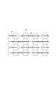
- FIG. 3 is a plan view of the spacer layer 50B as viewed from the normal direction of the separator 50
- FIG. 4 is an enlarged view of a portion of FIG. 3.
- the partial cross section of the separator 50 seen in the vertical section of FIG. 2 corresponds to the cross section taken along line II-II in FIG. 4.
- the linear first convex portions 53 are an intermittent pattern (first pattern) of multiple stripes extending parallel to the second direction, and are formed to be equally spaced in the first direction.
- the linear second convex portions 54 are formed along a honeycomb pattern (second pattern).
- the honeycomb pattern is a pattern in which multiple hexagons are arranged so that they share sides. Since the first pattern and the second pattern partially overlap, there are multiple intersections where the first convex portions 53 and the second convex portions 54 intersect with each other.
- the stress difference generated between the first convex portions 53, which have a wide line width and a large thickness, and the second convex portions, which have a narrow line width and a small thickness, is alleviated, and the occurrence of wrinkles in the separator is significantly suppressed.
- FIGS. 5 and 6 are plan views of other examples of the spacer layer 50B, as viewed from the normal direction of the separator 50.
- the spacer layer 50B in each of FIGS. 5 and 6 has a pattern (first pattern) of multiple continuous stripes extending parallel to the second direction, and is formed to be equally spaced in the first direction.
- the pattern (second pattern) of the second convex portions 54 included in the spacer layer 50B in FIG. 5 is not a network pattern, and the multiple second convex portions 54 are spaced apart from each other and adjacent second convex portions intersect with each other.
- FIGS. 5 and 6 are network patterns, which is a lattice pattern in which multiple rhombuses are arranged so as to share sides with each other.
- the first pattern and the second pattern also partially overlap, and there are multiple intersections where the first convex portions 53 and the second convex portions 54 intersect with each other.
- a cylindrical lithium secondary battery having a wound electrode group has been described.
- the lithium secondary battery of this embodiment is not limited to the form of embodiment 1, and can be applied to other forms.
- the shape of the lithium secondary battery can be appropriately selected from various shapes such as cylindrical, rectangular, sheet, flat, etc., depending on the application.
- the shape of the electrode group is also not particularly limited, and may be a laminated type.
- the battery includes a positive electrode, a negative electrode, a separator disposed between the positive electrode and the negative electrode, and a non-aqueous electrolyte.
- the separator has an elongated shape having a length D1 in a first direction and a length D2 (D1 ⁇ D2) in a second direction perpendicular to the first direction,
- the separator has a base layer and a spacer layer, the spacer layer includes a linear first convex portion having a first pattern and a linear second convex portion having a second pattern different from the first pattern, a line width of the first convex portion and a line width of the second convex portion differ from each other.
- the electrode has an elongated shape having a length D1 in a first direction and a length D2 (D1 ⁇ D2) in a second direction perpendicular to the first direction, A substrate layer and a spacer layer, the spacer layer includes a linear first convex portion having a first pattern and a linear second convex portion having a second pattern different from the first pattern, A separator, wherein the first convex portion and the second convex portion have different line widths.
- the separator according to technique 10 wherein the first pattern and the second pattern partially overlap each other.
- Technique 12 12.
- a thickness T1 of the first convex portion is greater than a thickness T2 of the second convex portion.
- the separator according to technique 12 wherein the thickness T1 of the first convex portion is three times or more the thickness T2 of the second convex portion.
- Technique 14 When a positive electrode and a negative electrode are wound with the separator interposed therebetween to form an electrode group having a plurality of turns and a winding axis parallel to the first direction, 14.
- NCA rock salt type lithium-containing transition metal oxide
- AB conductive material
- PVdF polyvinylidene fluoride
- NMP N-methyl-2-pyrrolidone
- the obtained positive electrode mixture slurry was applied to both sides of a strip-shaped Al foil (positive electrode current collector), dried, and the coating film of the positive electrode mixture was rolled using a roller. Finally, the resulting laminate of the positive electrode current collector and the positive electrode mixture was cut to a predetermined electrode size to obtain a positive electrode having a positive electrode mixture layer on both sides of the positive electrode current collector.
- Substrate Layer A microporous thin polyethylene film having a thickness of 20 ⁇ m was prepared.
- a dispersion of the spacer material was prepared by mixing 60 parts by volume of insulating particles (median diameter 3 ⁇ m, volume resistivity 10 ⁇ cm), 39 parts by volume of alkyd resin as a binder resin, 1 part by volume of CMC (sodium salt), and water as a dispersion medium.
- the line width of the first convex portion was 1 mm, and the line width of the second convex portion was 0.3 mm.
- the ratio of the area of the main surface of the base material layer that was covered by the first convex portions was set to 10%.
- the ratio of the area of the main surface of the base layer that was covered by the second convex portions was set to 11.6%.
- the positive electrode and the negative electrode current collector were spirally wound with the separator interposed therebetween to prepare an electrode group.
- the separator was arranged so that the spacer layer faced the negative electrode.
- the electrode group was housed in a bag-shaped exterior body formed of a laminate sheet having an Al layer, and after injecting a non-aqueous electrolyte, the exterior body was sealed to complete the lithium secondary battery A1.
- Example 2 A lithium secondary battery A2 was prepared in the same manner as in Example 1, except that in the formation of the spacer layer (4), the line width of the second convex portion was changed to 0.15 mm (the proportion of the C region to the total of the C region and the D region was 5.9%).
- Example 3 A lithium secondary battery A3 was produced in the same manner as in Example 1, except that in the formation of the spacer layer (4), the line width of the second convex portion was changed to 0.075 mm (the proportion of the C region to the total of the C region and the D region was 3%).
- Example 4 A lithium secondary battery A4 was produced in the same manner as in Example 1, except that in the formation of the spacer layer (4), the thickness of the second convex portion was changed as shown in Table 1.
- the battery was charged at a constant current of 2.15 mA per unit area (cm 2 ) of the electrode until the battery voltage reached 4.1 V, and then charged at a constant voltage of 4.1 V until the current value per unit area of the electrode reached 0.54 mA.
- the thickness was measured at any five points in the laminate, and the arithmetic average of the five measured values was taken as the average thickness of the laminate.
- the average thickness X obtained by subtracting the thicknesses of the two base layers from this average thickness was obtained.
- the ratio (%) of the average thickness X in the second cycle to the average thickness X before charge and discharge was taken as the expansion coefficient of the electrode group. That is, the expansion coefficient (%) of the electrode group is the ratio of the average thickness X in the second cycle when the average thickness X before charge and discharge is taken as 100%.
- discharge capacity retention rate The above charge and discharge constituted one cycle, and the charge and discharge were repeated up to 100 cycles. The ratio (%) of the discharge capacity at the 100th cycle to the discharge capacity at the first cycle was calculated as the discharge capacity retention rate. The discharge capacity at the first cycle was also defined as the initial discharge capacity.
- the evaluation results are shown in Table 1, along with the structure of the spacer layer.
- the expansion rate of the electrode group is expressed as a relative value when the expansion rate of battery A2 is set to 100.
Landscapes
- Chemical & Material Sciences (AREA)
- Chemical Kinetics & Catalysis (AREA)
- Electrochemistry (AREA)
- General Chemical & Material Sciences (AREA)
- Engineering & Computer Science (AREA)
- Manufacturing & Machinery (AREA)
- Materials Engineering (AREA)
- Secondary Cells (AREA)
- Cell Separators (AREA)
Priority Applications (4)
| Application Number | Priority Date | Filing Date | Title |
|---|---|---|---|
| CN202380086846.9A CN120380634A (zh) | 2022-12-27 | 2023-12-15 | 锂二次电池和隔膜 |
| JP2024567492A JPWO2024143000A1 (https=) | 2022-12-27 | 2023-12-15 | |
| US19/140,883 US20260106327A1 (en) | 2022-12-27 | 2023-12-15 | Lithium secondary battery and separator |
| EP23911781.5A EP4645505A4 (en) | 2022-12-27 | 2023-12-15 | SECONDARY LITHIUM BATTERY AND SEPARATOR |
Applications Claiming Priority (2)
| Application Number | Priority Date | Filing Date | Title |
|---|---|---|---|
| JP2022-210610 | 2022-12-27 | ||
| JP2022210610 | 2022-12-27 |
Publications (1)
| Publication Number | Publication Date |
|---|---|
| WO2024143000A1 true WO2024143000A1 (ja) | 2024-07-04 |
Family
ID=91717336
Family Applications (1)
| Application Number | Title | Priority Date | Filing Date |
|---|---|---|---|
| PCT/JP2023/045070 Ceased WO2024143000A1 (ja) | 2022-12-27 | 2023-12-15 | リチウム二次電池およびセパレータ |
Country Status (5)
| Country | Link |
|---|---|
| US (1) | US20260106327A1 (https=) |
| EP (1) | EP4645505A4 (https=) |
| JP (1) | JPWO2024143000A1 (https=) |
| CN (1) | CN120380634A (https=) |
| WO (1) | WO2024143000A1 (https=) |
Cited By (2)
| Publication number | Priority date | Publication date | Assignee | Title |
|---|---|---|---|---|
| WO2025022868A1 (ja) * | 2023-07-27 | 2025-01-30 | パナソニックIpマネジメント株式会社 | リチウム二次電池およびセパレータ |
| WO2025022867A1 (ja) * | 2023-07-27 | 2025-01-30 | パナソニックIpマネジメント株式会社 | リチウム二次電池およびセパレータ |
Citations (11)
| Publication number | Priority date | Publication date | Assignee | Title |
|---|---|---|---|---|
| JPS57115168U (https=) * | 1981-01-08 | 1982-07-16 | ||
| JPH02160365A (ja) * | 1989-10-26 | 1990-06-20 | Matsushita Electric Ind Co Ltd | 鉛蓄電池用袋状セパレータの製造法 |
| JPH052369U (ja) * | 1991-06-26 | 1993-01-14 | 日本無機株式会社 | 鉛蓄電池用リブ付きセパレータ |
| JP2000182593A (ja) * | 1998-12-10 | 2000-06-30 | Nippon Muki Co Ltd | 鉛蓄電池用袋状リブ付きセパレ―タ |
| JP2009224248A (ja) * | 2008-03-18 | 2009-10-01 | Panasonic Corp | 鉛蓄電池 |
| JP2010140772A (ja) * | 2008-12-12 | 2010-06-24 | Panasonic Corp | 鉛蓄電池 |
| JP2011527822A (ja) * | 2008-07-10 | 2011-11-04 | ジョンソン コントロールズ テクノロジー カンパニー | 強化型電池セパレータ |
| JP2019212606A (ja) * | 2018-05-31 | 2019-12-12 | パナソニックIpマネジメント株式会社 | リチウム二次電池 |
| JP2020123447A (ja) * | 2019-01-29 | 2020-08-13 | 古河電池株式会社 | 鉛蓄電池 |
| JP2021515969A (ja) * | 2018-03-09 | 2021-06-24 | ダラミック エルエルシー | 鉛蓄電池セパレータ及び関連する方法 |
| WO2021192645A1 (ja) | 2020-03-27 | 2021-09-30 | パナソニックIpマネジメント株式会社 | リチウム二次電池 |
Family Cites Families (1)
| Publication number | Priority date | Publication date | Assignee | Title |
|---|---|---|---|---|
| CN115548574A (zh) * | 2017-04-28 | 2022-12-30 | 恩特克亚洲株式会社 | 铅蓄电池用隔板 |
-
2023
- 2023-12-15 EP EP23911781.5A patent/EP4645505A4/en active Pending
- 2023-12-15 WO PCT/JP2023/045070 patent/WO2024143000A1/ja not_active Ceased
- 2023-12-15 JP JP2024567492A patent/JPWO2024143000A1/ja active Pending
- 2023-12-15 CN CN202380086846.9A patent/CN120380634A/zh active Pending
- 2023-12-15 US US19/140,883 patent/US20260106327A1/en active Pending
Patent Citations (11)
| Publication number | Priority date | Publication date | Assignee | Title |
|---|---|---|---|---|
| JPS57115168U (https=) * | 1981-01-08 | 1982-07-16 | ||
| JPH02160365A (ja) * | 1989-10-26 | 1990-06-20 | Matsushita Electric Ind Co Ltd | 鉛蓄電池用袋状セパレータの製造法 |
| JPH052369U (ja) * | 1991-06-26 | 1993-01-14 | 日本無機株式会社 | 鉛蓄電池用リブ付きセパレータ |
| JP2000182593A (ja) * | 1998-12-10 | 2000-06-30 | Nippon Muki Co Ltd | 鉛蓄電池用袋状リブ付きセパレ―タ |
| JP2009224248A (ja) * | 2008-03-18 | 2009-10-01 | Panasonic Corp | 鉛蓄電池 |
| JP2011527822A (ja) * | 2008-07-10 | 2011-11-04 | ジョンソン コントロールズ テクノロジー カンパニー | 強化型電池セパレータ |
| JP2010140772A (ja) * | 2008-12-12 | 2010-06-24 | Panasonic Corp | 鉛蓄電池 |
| JP2021515969A (ja) * | 2018-03-09 | 2021-06-24 | ダラミック エルエルシー | 鉛蓄電池セパレータ及び関連する方法 |
| JP2019212606A (ja) * | 2018-05-31 | 2019-12-12 | パナソニックIpマネジメント株式会社 | リチウム二次電池 |
| JP2020123447A (ja) * | 2019-01-29 | 2020-08-13 | 古河電池株式会社 | 鉛蓄電池 |
| WO2021192645A1 (ja) | 2020-03-27 | 2021-09-30 | パナソニックIpマネジメント株式会社 | リチウム二次電池 |
Non-Patent Citations (1)
| Title |
|---|
| See also references of EP4645505A1 |
Cited By (2)
| Publication number | Priority date | Publication date | Assignee | Title |
|---|---|---|---|---|
| WO2025022868A1 (ja) * | 2023-07-27 | 2025-01-30 | パナソニックIpマネジメント株式会社 | リチウム二次電池およびセパレータ |
| WO2025022867A1 (ja) * | 2023-07-27 | 2025-01-30 | パナソニックIpマネジメント株式会社 | リチウム二次電池およびセパレータ |
Also Published As
| Publication number | Publication date |
|---|---|
| JPWO2024143000A1 (https=) | 2024-07-04 |
| CN120380634A (zh) | 2025-07-25 |
| EP4645505A1 (en) | 2025-11-05 |
| US20260106327A1 (en) | 2026-04-16 |
| EP4645505A4 (en) | 2026-04-22 |
Similar Documents
| Publication | Publication Date | Title |
|---|---|---|
| CN112673504B (zh) | 锂二次电池 | |
| JP7813987B2 (ja) | リチウム二次電池 | |
| JP7194940B2 (ja) | リチウム二次電池 | |
| US20240194951A1 (en) | Lithium secondary battery | |
| EP3537522B1 (en) | Lithium secondary battery including lithium-ion conductive nonaqueous electrolyte | |
| JP2019212604A (ja) | リチウム二次電池 | |
| EP3537523B1 (en) | Lithium secondary battery including lithium-ion conductive nonaqueous electrolyte | |
| WO2024143000A1 (ja) | リチウム二次電池およびセパレータ | |
| EP3584875A1 (en) | Lithium secondary battery | |
| JP7162174B2 (ja) | リチウム二次電池 | |
| WO2024070854A1 (ja) | リチウム二次電池、リチウム二次電池用スペーサ、スペーサ材料およびリチウム二次電池用セパレータとスペーサの一体化物 | |
| WO2024048135A1 (ja) | リチウム二次電池および複合部材 | |
| WO2023234223A1 (ja) | リチウム二次電池および複合部材 | |
| WO2024048136A1 (ja) | リチウム二次電池および複合部材 | |
| JP7162175B2 (ja) | リチウム二次電池 | |
| WO2024143001A1 (ja) | リチウム二次電池およびセパレータ | |
| WO2025022868A1 (ja) | リチウム二次電池およびセパレータ | |
| WO2025022867A1 (ja) | リチウム二次電池およびセパレータ | |
| EP4675741A1 (en) | Lithium secondary battery | |
| WO2024181085A1 (ja) | リチウム二次電池 | |
| WO2025070578A1 (ja) | 二次電池 | |
| WO2026048847A1 (ja) | 二次電池 | |
| WO2025047688A1 (ja) | リチウム二次電池 | |
| WO2025047908A1 (ja) | リチウム二次電池 | |
| WO2024143005A1 (ja) | リチウム二次電池およびセパレータ |
Legal Events
| Date | Code | Title | Description |
|---|---|---|---|
| 121 | Ep: the epo has been informed by wipo that ep was designated in this application |
Ref document number: 23911781 Country of ref document: EP Kind code of ref document: A1 |
|
| WWE | Wipo information: entry into national phase |
Ref document number: 202380086846.9 Country of ref document: CN |
|
| WWE | Wipo information: entry into national phase |
Ref document number: 2024567492 Country of ref document: JP |
|
| WWE | Wipo information: entry into national phase |
Ref document number: 202547069697 Country of ref document: IN |
|
| WWP | Wipo information: published in national office |
Ref document number: 202380086846.9 Country of ref document: CN |
|
| WWE | Wipo information: entry into national phase |
Ref document number: 2023911781 Country of ref document: EP |
|
| NENP | Non-entry into the national phase |
Ref country code: DE |
|
| ENP | Entry into the national phase |
Ref document number: 2023911781 Country of ref document: EP Effective date: 20250728 |
|
| WWP | Wipo information: published in national office |
Ref document number: 202547069697 Country of ref document: IN |
|
| ENP | Entry into the national phase |
Ref document number: 2023911781 Country of ref document: EP Effective date: 20250728 |
|
| WWP | Wipo information: published in national office |
Ref document number: 2023911781 Country of ref document: EP |