WO2024142998A1 - 樹脂成形品の製造方法、射出成形型および樹脂成形品 - Google Patents
樹脂成形品の製造方法、射出成形型および樹脂成形品 Download PDFInfo
- Publication number
- WO2024142998A1 WO2024142998A1 PCT/JP2023/045050 JP2023045050W WO2024142998A1 WO 2024142998 A1 WO2024142998 A1 WO 2024142998A1 JP 2023045050 W JP2023045050 W JP 2023045050W WO 2024142998 A1 WO2024142998 A1 WO 2024142998A1
- Authority
- WO
- WIPO (PCT)
- Prior art keywords
- molding
- mold
- molded product
- space
- resin molded
- Prior art date
- Legal status (The legal status is an assumption and is not a legal conclusion. Google has not performed a legal analysis and makes no representation as to the accuracy of the status listed.)
- Ceased
Links
Images


Classifications
-
- F—MECHANICAL ENGINEERING; LIGHTING; HEATING; WEAPONS; BLASTING
- F16—ENGINEERING ELEMENTS AND UNITS; GENERAL MEASURES FOR PRODUCING AND MAINTAINING EFFECTIVE FUNCTIONING OF MACHINES OR INSTALLATIONS; THERMAL INSULATION IN GENERAL
- F16J—PISTONS; CYLINDERS; SEALINGS
- F16J15/00—Sealings
- F16J15/16—Sealings between relatively-moving surfaces
- F16J15/18—Sealings between relatively-moving surfaces with stuffing-boxes for elastic or plastic packings
- F16J15/188—Split assemblies
-
- B—PERFORMING OPERATIONS; TRANSPORTING
- B29—WORKING OF PLASTICS; WORKING OF SUBSTANCES IN A PLASTIC STATE IN GENERAL
- B29C—SHAPING OR JOINING OF PLASTICS; SHAPING OF MATERIAL IN A PLASTIC STATE, NOT OTHERWISE PROVIDED FOR; AFTER-TREATMENT OF THE SHAPED PRODUCTS, e.g. REPAIRING
- B29C45/00—Injection moulding, i.e. forcing the required volume of moulding material through a nozzle into a closed mould; Apparatus therefor
- B29C45/17—Component parts, details or accessories; Auxiliary operations
- B29C45/40—Removing or ejecting moulded articles
- B29C45/44—Removing or ejecting moulded articles for undercut articles
-
- B—PERFORMING OPERATIONS; TRANSPORTING
- B29—WORKING OF PLASTICS; WORKING OF SUBSTANCES IN A PLASTIC STATE IN GENERAL
- B29C—SHAPING OR JOINING OF PLASTICS; SHAPING OF MATERIAL IN A PLASTIC STATE, NOT OTHERWISE PROVIDED FOR; AFTER-TREATMENT OF THE SHAPED PRODUCTS, e.g. REPAIRING
- B29C33/00—Moulds or cores; Details thereof or accessories therefor
- B29C33/44—Moulds or cores; Details thereof or accessories therefor with means for, or specially constructed to facilitate, the removal of articles, e.g. of undercut articles
-
- B—PERFORMING OPERATIONS; TRANSPORTING
- B29—WORKING OF PLASTICS; WORKING OF SUBSTANCES IN A PLASTIC STATE IN GENERAL
- B29C—SHAPING OR JOINING OF PLASTICS; SHAPING OF MATERIAL IN A PLASTIC STATE, NOT OTHERWISE PROVIDED FOR; AFTER-TREATMENT OF THE SHAPED PRODUCTS, e.g. REPAIRING
- B29C45/00—Injection moulding, i.e. forcing the required volume of moulding material through a nozzle into a closed mould; Apparatus therefor
- B29C45/17—Component parts, details or accessories; Auxiliary operations
- B29C45/26—Moulds
- B29C45/2616—Moulds having annular mould cavities
-
- B—PERFORMING OPERATIONS; TRANSPORTING
- B29—WORKING OF PLASTICS; WORKING OF SUBSTANCES IN A PLASTIC STATE IN GENERAL
- B29C—SHAPING OR JOINING OF PLASTICS; SHAPING OF MATERIAL IN A PLASTIC STATE, NOT OTHERWISE PROVIDED FOR; AFTER-TREATMENT OF THE SHAPED PRODUCTS, e.g. REPAIRING
- B29C45/00—Injection moulding, i.e. forcing the required volume of moulding material through a nozzle into a closed mould; Apparatus therefor
- B29C45/17—Component parts, details or accessories; Auxiliary operations
- B29C45/26—Moulds
- B29C45/27—Sprue channels ; Runner channels or runner nozzles
-
- B—PERFORMING OPERATIONS; TRANSPORTING
- B29—WORKING OF PLASTICS; WORKING OF SUBSTANCES IN A PLASTIC STATE IN GENERAL
- B29C—SHAPING OR JOINING OF PLASTICS; SHAPING OF MATERIAL IN A PLASTIC STATE, NOT OTHERWISE PROVIDED FOR; AFTER-TREATMENT OF THE SHAPED PRODUCTS, e.g. REPAIRING
- B29C45/00—Injection moulding, i.e. forcing the required volume of moulding material through a nozzle into a closed mould; Apparatus therefor
- B29C45/17—Component parts, details or accessories; Auxiliary operations
- B29C45/26—Moulds
- B29C45/33—Moulds having transversely, e.g. radially, movable mould parts
-
- B—PERFORMING OPERATIONS; TRANSPORTING
- B29—WORKING OF PLASTICS; WORKING OF SUBSTANCES IN A PLASTIC STATE IN GENERAL
- B29C—SHAPING OR JOINING OF PLASTICS; SHAPING OF MATERIAL IN A PLASTIC STATE, NOT OTHERWISE PROVIDED FOR; AFTER-TREATMENT OF THE SHAPED PRODUCTS, e.g. REPAIRING
- B29C45/00—Injection moulding, i.e. forcing the required volume of moulding material through a nozzle into a closed mould; Apparatus therefor
- B29C45/17—Component parts, details or accessories; Auxiliary operations
- B29C45/40—Removing or ejecting moulded articles
- B29C45/44—Removing or ejecting moulded articles for undercut articles
- B29C45/4407—Removing or ejecting moulded articles for undercut articles by flexible movement of undercut portions of the articles
-
- B—PERFORMING OPERATIONS; TRANSPORTING
- B29—WORKING OF PLASTICS; WORKING OF SUBSTANCES IN A PLASTIC STATE IN GENERAL
- B29D—PRODUCING PARTICULAR ARTICLES FROM PLASTICS OR FROM SUBSTANCES IN A PLASTIC STATE
- B29D99/00—Subject matter not provided for in other groups of this subclass
- B29D99/0053—Producing sealings
-
- B—PERFORMING OPERATIONS; TRANSPORTING
- B29—WORKING OF PLASTICS; WORKING OF SUBSTANCES IN A PLASTIC STATE IN GENERAL
- B29D—PRODUCING PARTICULAR ARTICLES FROM PLASTICS OR FROM SUBSTANCES IN A PLASTIC STATE
- B29D99/00—Subject matter not provided for in other groups of this subclass
- B29D99/0082—Producing articles in the form of closed loops, e.g. rings
-
- F—MECHANICAL ENGINEERING; LIGHTING; HEATING; WEAPONS; BLASTING
- F16—ENGINEERING ELEMENTS AND UNITS; GENERAL MEASURES FOR PRODUCING AND MAINTAINING EFFECTIVE FUNCTIONING OF MACHINES OR INSTALLATIONS; THERMAL INSULATION IN GENERAL
- F16J—PISTONS; CYLINDERS; SEALINGS
- F16J15/00—Sealings
- F16J15/16—Sealings between relatively-moving surfaces
- F16J15/32—Sealings between relatively-moving surfaces with elastic sealings, e.g. O-rings
- F16J15/3268—Mounting of sealing rings
- F16J15/3272—Mounting of sealing rings the rings having a break or opening, e.g. to enable mounting on a shaft otherwise than from a shaft end
-
- F—MECHANICAL ENGINEERING; LIGHTING; HEATING; WEAPONS; BLASTING
- F16—ENGINEERING ELEMENTS AND UNITS; GENERAL MEASURES FOR PRODUCING AND MAINTAINING EFFECTIVE FUNCTIONING OF MACHINES OR INSTALLATIONS; THERMAL INSULATION IN GENERAL
- F16J—PISTONS; CYLINDERS; SEALINGS
- F16J15/00—Sealings
- F16J15/16—Sealings between relatively-moving surfaces
- F16J15/32—Sealings between relatively-moving surfaces with elastic sealings, e.g. O-rings
- F16J15/328—Manufacturing methods specially adapted for elastic sealings
-
- B—PERFORMING OPERATIONS; TRANSPORTING
- B29—WORKING OF PLASTICS; WORKING OF SUBSTANCES IN A PLASTIC STATE IN GENERAL
- B29C—SHAPING OR JOINING OF PLASTICS; SHAPING OF MATERIAL IN A PLASTIC STATE, NOT OTHERWISE PROVIDED FOR; AFTER-TREATMENT OF THE SHAPED PRODUCTS, e.g. REPAIRING
- B29C45/00—Injection moulding, i.e. forcing the required volume of moulding material through a nozzle into a closed mould; Apparatus therefor
- B29C45/0025—Preventing defects on the moulded article, e.g. weld lines, shrinkage marks
- B29C2045/0034—Mould parting lines
-
- B—PERFORMING OPERATIONS; TRANSPORTING
- B29—WORKING OF PLASTICS; WORKING OF SUBSTANCES IN A PLASTIC STATE IN GENERAL
- B29L—INDEXING SCHEME ASSOCIATED WITH SUBCLASS B29C, RELATING TO PARTICULAR ARTICLES
- B29L2031/00—Other particular articles
- B29L2031/26—Sealing devices, e.g. packaging for pistons or pipe joints
Definitions
- An injection molding die has a first surface and a second surface located on opposite sides of each other, and an inner peripheral surface and an outer peripheral surface between the first surface and the second surface, and is used to manufacture an arc-shaped resin molded product including a first end and a second end, and is provided with an inner mold having an inner peripheral molding surface that forms the inner peripheral surface, and an outer mold having an outer peripheral molding surface that forms the outer peripheral surface, and a molding groove is formed in the inner peripheral surface of the outer mold along the circumferential direction, and the molding groove has a first side surface that forms a first outer region of the first surface and a second side surface that forms a second outer region of the second surface, with the outer peripheral molding surface as a bottom surface, and the inner mold includes a first molding surface that forms a first inner region inside the first outer region of the first surface, and a second molding surface that forms a second inner region inside the second outer region of the second surface.
- FIG. 1 is a cross-sectional view of a sealing structure according to a first embodiment.
- FIG. FIG. 3 is a cross-sectional view taken along line III-III in FIG. 2.
- FIG. 5 is a cross-sectional view taken along line VV in FIG. 4 .
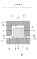
- FIG. 2 is a cross-sectional view of an injection molding die.
- FIG. 7 is an enlarged view of region VII in FIG. 6.
- FIG. FIG. FIG. 2 is a plan view of the internal space of the injection mold.
- FIG. 2 is a cross-sectional view of the outer mold.
- A: First embodiment A-1: Sealing structure 100 Fig. 1 is a cross-sectional view illustrating a configuration of a sealing structure 100 according to a first embodiment.
- the sealing structure 100 is a mechanism employed in a transmission such as an automatic transmission (AT) or a continuously variable transmission (CVT).
- AT automatic transmission
- CVT continuously variable transmission
- the sealing structure 100 includes a housing 11, a shaft member 12, and a seal ring 20.
- the central axis C of the seal ring 20 is assumed.
- One direction along the central axis C is referred to as the X1 direction, and the direction opposite to the X1 direction is referred to as the X2 direction.
- Space 152 is located in the X2 direction of space 151.
- the X1 direction and the X2 direction are collectively referred to as the "axial direction X”.
- the central axis C is also referred to as the central axis of the shaft hole 112 of the housing 11, or the central axis of the shaft member 12.
- the shaft member 12 is rotatable around the central axis C.
- the direction along the circumference of an imaginary circle of any diameter centered on the central axis C is referred to as the "circumferential direction,” and the direction of the radius of the imaginary circle is referred to as the "radial direction.”
- the radial direction toward the central axis C is referred to as the “inner side,” and the direction away from the central axis C is referred to as the “outer side.”
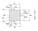
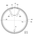
- A-2: Seal ring 20 Fig. 2 is a plan view of the seal ring 20, and Fig. 3 is a cross-sectional view taken along line III-III in Fig. 2.
- the seal ring 20 of the first embodiment is a solid seal ring portion including a joint portion 21 and a body portion 22.
- the seal ring 20 is an arc-shaped structure including a first end E1 and a second end E2.
- the first end E1 and the second end E2 overlap each other in the circumferential direction.
- the first end E1 and the second end E2 form a joint 21 located at one point in the circumferential direction.
- the seal ring 20 of the first embodiment is an arc-shaped member in which a circular member is cut at one point, and the cut point is the joint 21.
- the first end E1 and the second end E2 are configured to be relatively movable along the circumferential direction.
- the seal ring 20 is attached to the shaft member 12 with the first end E1 and the second end E2 spaced apart from each other.
- the arc-shaped portion of the seal ring 20 other than the joint portion 21 is the body portion 22.
- the dimensions and shape of the cross section perpendicular to the circumferential direction of the seal ring 20 are substantially the same throughout the entire body portion 22 other than each end (first end E1, second end E2).
- space 151 is at a higher pressure than space 152. Therefore, as illustrated in FIG. 1, the seal ring 20 is pressed in the X2 direction inside the mounting groove 13.
- the first surface F1 faces the side surface 131 of the mounting groove 13 with a gap therebetween, and the second surface F2 is in close contact with the side surface 132 of the mounting groove 13.
- the inner circumferential surface Ga faces the bottom surface 133 of the mounting groove 13 with a gap therebetween, and the outer circumferential surface Gb is in close contact with the inner circumferential surface 113 of the housing 11 over its entirety.
- the second surface F2 includes a second inner region F2a and a second outer region F2b.
- the second inner region F2a is an arc-shaped region of a predetermined width that includes the inner peripheral edge of the second surface F2.
- the second outer region F2b is an arc-shaped region of a predetermined width that includes the outer peripheral edge of the second surface F2. Therefore, the second inner region F2a is located inside the second outer region F2b.
- FIG. 3 illustrates the boundary B2 between the second outer region F2b and the second inner region F2a.
- the boundary B2 corresponds to the parting line of the injection molding die 200. As illustrated in FIG. 1, a part of the second inner region F2a of the second surface F2 is in close contact with the side surface 132 of the mounting groove 13. The second outer region F2b and the boundary B2 of the second surface F2 do not contact the side surface 132.
- the inner peripheral surface Ga of the seal ring 20 includes a first portion Ga1 and a second portion Ga2.
- the first portion Ga1 is an area adjacent to the first surface F1
- the second portion Ga2 is an area adjacent to the second surface F2. Therefore, the first portion Ga1 is located in the X1 direction relative to the second portion Ga2.
- FIG. 3 illustrates the boundary B12 between the first portion Ga1 and the second portion Ga2.
- the boundary B12 corresponds to the parting line of the injection molding die 200.
- the dimension H1 (height) of the gripping portion 44 in the axial direction X exceeds the dimension T (thickness) of the seal ring 20 in the axial direction X (H1>T).
- the end 441 in the X1 direction of the gripping portion 44 is located in the X1 direction further than the first surface F1 of the seal ring 20.
- the end 442 in the X2 direction of the gripping portion 44 is located in the X2 direction further than the second surface F2 of the seal ring 20.
- the dimension H2 of the connecting portion 45 in the axial direction X is smaller than the dimension T of the seal ring 20 in the axial direction X (H2 ⁇ T).
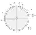
- the molding flow path 72 is a space for molding the seal ring 20. Specifically, the molding flow path 72 is formed in an arc shape from end e11 to end e12 along the outer periphery of the first opposing surface 71. End e11 is the end corresponding to the first end E1 of the seal ring 20, and end e12 is the end corresponding to the second end E2 of the seal ring 20.
- the flow path 73 in FIG. 8 is a space for forming a portion of the columnar portion 31 of the auxiliary molding part 30 that is located in the X1 direction.
- the flow path 73 is a through hole that has a circular cross-sectional shape and is located in the center of the first opposing surface 71.
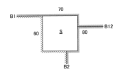
- Figure 9 is a plan view of the second opposing surface 81 of the second mold 80.
- the second opposing surface 81 is shaded for convenience.
- the second opposing surface 81 of the second mold 80 is formed with a molding flow path 82, a flow path 831, a flow path 832, molding holes 84a, molding holes 84b, a communication path 85a, and a communication path 85b.
- the molding flow path 82 is a groove space defined by a second molding surface 821 and a second inner peripheral surface 822 that intersect with each other.
- the second molding surface 821 is an arc-shaped area in a plane perpendicular to the central axis C, and corresponds to the bottom surface of the molding flow path 82.
- the second inner peripheral surface 822 is an arc-shaped surface centered on the central axis C, and corresponds to the side surface of the molding flow path 82.
- the second mold 80 includes the second molding surface 821 and the second inner peripheral surface 822.
- the boundary between the first inner circumferential surface 722 and the second inner circumferential surface 822 is located between the first surface F1 and the second surface F2 of the seal ring 20 in the axial direction X. That is, as illustrated in FIG. 3, the linear burr L12 formed between the first portion Ga1 and the second portion Ga2 of the inner circumferential surface Ga due to the boundary B12 between the first inner circumferential surface 722 and the second inner circumferential surface 822 is located between the first surface F1 and the second surface F2.
- the first space 531 is a space for forming the gripping portion 44 of the first tab 41.
- the first space 531 communicates with the molding space S via a communication passage 85a.
- the communication passage 85a is a space for forming the connecting portion 45 of the first tab 41.
- the communication passage 85a may be formed in the first mold 70.
- the second space 532 is a space for forming the gripping portion 44 of the second tab 42.
- the second space 532 communicates with the molding space S via a communication passage 85b.
- the communication passage 85b is a space for forming the connecting portion 45 of the second tab 42.
- the communication passage 85b may be formed in the first mold 70.
- spaces (molding holes 74a and 84a) for forming the gripping portion 44 of the first tab 41 are formed in both the first mold 70 and the second mold 80.
- spaces (molding holes 74b and 84b) for forming the gripping portion 44 of the second tab 42 are formed in both the first mold 70 and the second mold 80. Therefore, it is possible to form a first tab 41 and a second tab 42 that are easy to grip and have a sufficiently secured dimension H1 of the gripping portion 44 in the axial direction X.
- the first side 631 and the second side 632 are wall surfaces that intersect with the outer peripheral molding surface 64.
- the first side 631 and the second side 632 are arc-shaped surfaces in a plane perpendicular to the central axis C, and face each other at a predetermined distance.
- the first side 631 is located in the X1 direction relative to the second side 632.
- the second side surface 632 of the outer mold 60 and the second molding surface 821 of the inner mold 50 are located in the same plane. That is, the second side surface 632 and the second molding surface 821 are continuous without any step.
- the second side surface 632 and the second molding surface 821 are planes for forming the second surface F2 of the seal ring 20.
- the second molding surface 821 is an inner wall surface for forming the second inner region F2a of the second surface F2
- the second side surface 632 is an inner wall surface for forming the second outer region F2b of the second surface F2. That is, the region of the second surface F2 formed by the second molding surface 821 is the second inner region F2a, and the region of the second surface F2 formed by the second side surface 632 is the second outer region F2b.
- the second embodiment achieves the same effect as the first embodiment.
- the second tab 42 of the first embodiment is omitted, so there is no need to remove the second tab 42 in the removal step P5. Therefore, the removal step P5 can be simplified compared to the first embodiment.
- the third embodiment achieves the same effects as the first embodiment.
- the resin material can be efficiently supplied to the molding space S by two systems, the first supply flow path 521 and the second supply flow path 522.
- the intermediate molded product 300 is demolded from the outer mold 60 by moving the protrusion connected to the inner peripheral surface Ga of the seal ring 20.
- the first tab 41 and the second tab 42 in the first embodiment, the first tab 41 and the auxiliary molding portion 30 in the second embodiment (FIG. 18), and the first auxiliary molding portion 301 and the second auxiliary molding portion 302 in the third embodiment (FIG. 20) are examples of "protrusions".
- one of the first tab 41 and the second tab 42 in the first embodiment is an example of a "first protrusion", and the other is an example of a "second protrusion".
- One of the first tab 41 and the auxiliary molding portion 30 in the second embodiment is an example of a "first protrusion”, and the other is an example of a "second protrusion”.
- One of the first auxiliary molding portions 301 in the third embodiment is an example of a "first protrusion", and the other is an example of a "second protrusion”.
- the intermediate molded product 300 is released from the outer mold 60 by the movement of two protrusions in the demolding process P4, but the number of protrusions that move in the demolding process P4 is not limited to the above examples.
- the intermediate molded product 300 may be released by the movement of one protrusion in the demolding process P4.
- first tab 41 or the second tab 42 may be moved.
- first tab 41 or the auxiliary molding portion 30 may be moved.
- first auxiliary molding portion 301 or the second auxiliary molding portion 302 may be moved.
- the intermediate molded product 300 may be released from the outer mold 60 by moving three or more protrusions.
- the resin molded product to which the present disclosure applies is not limited to the seal ring 20.
- the present disclosure also applies to a backup ring that is arranged alongside an annular seal to prevent the seal from wedging into a gap, as in the above-described embodiments.
- the backup ring is an arc-shaped member formed by cutting an annular member at one location.
- the backup ring is an arc-shaped resin molded product that includes a first end and a second end, similar to the seal ring 20 in each of the above-described embodiments.
- both corners A1 and A2 of the seal ring 20 are rounded, but embodiments in which only one of corners A1 and A2 is rounded are also envisioned. Therefore, only one of corners a1 and a2 of the outer mold 60 may be rounded. Also, the rounded shape of corners A1 or A2 may be omitted. The rounded shape of corners a1 or a2 may be omitted.
- the cross-sectional shape of the seal ring 20 is substantially rectangular, but the cross-sectional shape of the seal ring 20 is not limited to the above examples.
- embodiment 1 illustrated in FIG. 21 or embodiment 2 illustrated in FIG. 22 are also envisioned.
- Linear burrs L1 are formed on the first surface F1 in an area other than the step portion 23, and linear burrs L2 are formed on the second surface F2 in an area other than the step portion 24.
- the area (sliding area) of the second surface F2 in contact with the side surface 132 of the mounting groove 13 is reduced compared to the above-mentioned embodiments. Therefore, the sliding resistance between the second surface F2 and the side surface 132 is reduced, resulting in low friction and low torque.
- the seal ring 20 of aspect 2 is formed with a step portion 25 and a step portion 26.
- the step portion 25 is a recess formed in an arc shape along the outer periphery of the surface of the seal ring 20 facing the X1 direction.
- the bottom surface of the step portion 25 is the first surface F1.
- the step portion 26 is a recess formed in an arc shape along the outer periphery of the surface of the seal ring 20 facing the X2 direction.
- the bottom surface of the step portion 26 is the second surface F2.
- a linear burr L1 is formed on the first surface F1, and a linear burr L2 is formed on the second surface F2.
- the outer peripheral surface Gb in embodiment 2 is the outer peripheral surface of an arc-shaped protrusion that protrudes outward from the inner wall surface of step portion 25 and step portion 26.
- the area (sliding area) where outer peripheral surface Gb contacts inner peripheral surface 113 of shaft hole 112 is reduced compared to the above-mentioned embodiments. Therefore, the sliding resistance between outer peripheral surface Gb and inner peripheral surface 113 is reduced, resulting in low friction and low torque.
- the sealing structure 100 is used in a transmission, but the uses of the sealing structure 100 are not limited to the above examples.
- the sealing structure 100 in each of the above embodiments can be used for any purpose, such as an engine seal, a differential seal, a motor seal, or a hub bearing seal.
- nth (n is a natural number) in this application is used only as a formal and convenient label to distinguish each element in the description and does not have any substantive meaning. Therefore, there is no room for restrictive interpretation of the position of each element or the order of manufacture, etc., based on the term "nth.”
- a method for manufacturing a resin molded product according to one aspect (aspect 1) of the present disclosure is a method for manufacturing an arc-shaped resin molded product having a first surface and a second surface located on opposite sides of each other along the axial direction, an inner peripheral surface and an outer peripheral surface between the first surface and the second surface, and including a first end and a second end, and includes a molding step of forming an intermediate molded product including the resin molded product and one or more protrusions connected to the inner peripheral surface of the resin molded product by supplying a resin material to an internal space of an injection molding die including an inner mold having an inner peripheral molding surface that forms the inner peripheral surface and an outer mold having an outer peripheral molding surface that forms the outer peripheral surface, a mold opening step of removing the inner mold, and a demolding step of releasing the intermediate molded product from the outer mold by moving the one or more protrusions.
- the resin molded product is released from the outer mold by moving one or more protrusions molded together with the resin molded product. Therefore, the resin molded product can be easily demolded.
- a removal step of removing one or more protrusions from the intermediate molded product may be performed after the demolding step.
- the injection mold has an opposing surface that faces the outer peripheral surface, and the opposing surface does not have a parting line that is the boundary between the inner mold and the outer mold.
- the one or more protrusions include a first protrusion and a second protrusion, and in the demolding step, the first protrusion and the second protrusion are brought close to each other to release the resin molded product from the outer mold.
- the resin molded product can be released from the outer mold by the simple process of bringing the first protrusion and the second protrusion close to each other.
- the internal space includes an arc-shaped molding space that forms the resin molded product, a supply flow path for supplying the resin material to the molding space, a first space that forms the first protrusion, and a second space that forms the second protrusion, and the supply flow path communicates with a specific point of the molding space in the circumferential direction of the molding space, the first space communicates with a point in the molding space between the specific point and an end corresponding to the first end, and the second space communicates with a point in the molding space between the specific point and an end corresponding to the second end.
- the first space and the second space are installed on both sides in the circumferential direction of the molding space, sandwiching a specific position where the supply flow path (gate) communicates. Therefore, the resin material supplied from the supply flow path can be effectively filled up to both ends of the molding space and the first and second spaces.
- a form in which the first protrusion is formed near the first end and the second protrusion is formed near the second end can be adopted.
- the resin molded product can be easily released from the outer mold by bringing the first protrusion and the second protrusion closer to each other.
- a molding groove is formed in the inner peripheral surface of the outer mold along the circumferential direction, and the molding groove has a first side surface forming a first outer region of the first surface and a second side surface forming a second outer region of the second surface, with the outer peripheral molding surface as a bottom surface, and the inner mold includes a first molding surface forming a first inner region inside the first outer region of the first surface, and a second molding surface forming a second inner region inside the second outer region of the second surface.
- the boundary between the first side surface of the outer mold and the first molding surface of the inner mold faces the first surface of the resin molded product
- the boundary between the second side surface of the outer mold and the second molding surface of the inner mold faces the second surface of the resin molded product.
- the boundary between the outer mold and the inner mold does not face the outer peripheral surface of the resin molded product.
- the inner mold includes a first mold including the first molding surface and a first inner peripheral surface of the inner peripheral molding surface, and a second mold including the second molding surface and a second inner peripheral surface of the inner peripheral molding surface, and the boundary between the first inner peripheral surface and the second inner peripheral surface is located between the first surface and the second surface in the axial direction.
- the boundary between the first inner peripheral surface of the first mold and the second inner peripheral surface of the second mold is located between the first surface and the second surface. Therefore, it is possible to avoid the formation of linear burrs corresponding to the boundary between the first mold and the second mold along the edge of the first surface side or the edge of the second surface side of the inner peripheral surface of the resin molded product.
- a first molding hole that forms a part of the one or more protrusions is formed in a first opposing surface of the first mold that faces the second mold, and a second molding hole that forms another part of the one or more protrusions is formed in a second opposing surface of the second mold that faces the first mold.
- spaces (first molding hole, second molding hole) for forming the protrusions are formed in both the first mold and the second mold, it is possible to form a protrusion that is easy to grip and has a sufficient axial dimension.
- An injection molding die has a first surface and a second surface located on opposite sides of each other along the axial direction, and an inner peripheral surface and an outer peripheral surface between the first surface and the second surface, and is used to manufacture an arc-shaped resin molded product including a first end and a second end, and is provided with an inner mold having an inner peripheral molding surface that forms the inner peripheral surface, and an outer mold having an outer peripheral molding surface that forms the outer peripheral surface, and a molding groove is formed in the inner peripheral surface of the outer mold along the circumferential direction, and the molding groove has a first side surface that forms a first outer region of the first surface and a second side surface that forms a second outer region of the second surface, with the outer peripheral molding surface as a bottom surface, and the inner mold includes a first molding surface that forms a first inner region inside the first outer region of the first surface, and a second molding surface that forms a second inner region inside the second outer region of the second surface.
- a resin molded product according to one aspect (aspect 11) of the present disclosure is an arc-shaped resin molded product including a first surface and a second surface located on opposite sides of each other along the axial direction, an inner peripheral surface and an outer peripheral surface between the first surface and the second surface, and a first end portion and a second end portion, in which a linear first protrusion is formed along the circumferential direction between a first outer region of the first surface including the outer peripheral edge of the first surface and a first inner region located inside the first outer region and including the inner peripheral edge of the first surface, and a linear second protrusion is formed along the circumferential direction between a second outer region of the second surface including the outer peripheral edge of the second surface and a second inner region located inside the second outer region and including the inner peripheral edge of the second surface.
- the outer peripheral surface is free of linear burrs that correspond to the parting line of the injection molding die over the entire area, including the periphery of the outer peripheral surface.
Landscapes
- Engineering & Computer Science (AREA)
- Mechanical Engineering (AREA)
- Manufacturing & Machinery (AREA)
- General Engineering & Computer Science (AREA)
- Moulds For Moulding Plastics Or The Like (AREA)
- Sealing Devices (AREA)
- Injection Moulding Of Plastics Or The Like (AREA)
Priority Applications (3)
| Application Number | Priority Date | Filing Date | Title |
|---|---|---|---|
| KR1020257018468A KR20250103739A (ko) | 2022-12-26 | 2023-12-15 | 수지 성형품의 제조 방법, 사출 성형형 및 수지 성형품 |
| EP23911779.9A EP4644080A1 (en) | 2022-12-26 | 2023-12-15 | Production method for resin molding, injection molding mold, and resin molding |
| CN202380083437.3A CN120322322A (zh) | 2022-12-26 | 2023-12-15 | 树脂模制品的制造方法、注射模具和树脂模制品 |
Applications Claiming Priority (2)
| Application Number | Priority Date | Filing Date | Title |
|---|---|---|---|
| JP2022208612A JP7291843B1 (ja) | 2022-12-26 | 2022-12-26 | 樹脂成形品の製造方法、射出成形型および樹脂成形品 |
| JP2022-208612 | 2022-12-26 |
Publications (1)
| Publication Number | Publication Date |
|---|---|
| WO2024142998A1 true WO2024142998A1 (ja) | 2024-07-04 |
Family
ID=86721477
Family Applications (1)
| Application Number | Title | Priority Date | Filing Date |
|---|---|---|---|
| PCT/JP2023/045050 Ceased WO2024142998A1 (ja) | 2022-12-26 | 2023-12-15 | 樹脂成形品の製造方法、射出成形型および樹脂成形品 |
Country Status (5)
| Country | Link |
|---|---|
| EP (1) | EP4644080A1 (https=) |
| JP (2) | JP7291843B1 (https=) |
| KR (1) | KR20250103739A (https=) |
| CN (1) | CN120322322A (https=) |
| WO (1) | WO2024142998A1 (https=) |
Citations (6)
| Publication number | Priority date | Publication date | Assignee | Title |
|---|---|---|---|---|
| JP2002089718A (ja) * | 1994-06-30 | 2002-03-27 | Ntn Corp | 合成樹脂製シールリング |
| US8245398B2 (en) * | 2009-03-04 | 2012-08-21 | Nok Corporation | Method of shape forming a seal-ring |
| JP2017133571A (ja) | 2016-01-26 | 2017-08-03 | Nok株式会社 | 密封装置 |
| JP2017207079A (ja) * | 2016-05-16 | 2017-11-24 | 三菱電線工業株式会社 | シールリングの製造方法及び射出成形金型 |
| JP2022000590A (ja) * | 2017-01-10 | 2022-01-04 | サン−ゴバン パフォーマンス プラスティクス エルプラスエス ゲーエムベーハー | 射出成形シールリングおよびそれらを製造する方法 |
| JP2022146093A (ja) * | 2021-03-22 | 2022-10-05 | Ntn株式会社 | シールリングの製造方法および成形金型 |
-
2022
- 2022-12-26 JP JP2022208612A patent/JP7291843B1/ja active Active
-
2023
- 2023-06-05 JP JP2023092599A patent/JP2024092916A/ja active Pending
- 2023-12-15 CN CN202380083437.3A patent/CN120322322A/zh active Pending
- 2023-12-15 KR KR1020257018468A patent/KR20250103739A/ko active Pending
- 2023-12-15 EP EP23911779.9A patent/EP4644080A1/en active Pending
- 2023-12-15 WO PCT/JP2023/045050 patent/WO2024142998A1/ja not_active Ceased
Patent Citations (6)
| Publication number | Priority date | Publication date | Assignee | Title |
|---|---|---|---|---|
| JP2002089718A (ja) * | 1994-06-30 | 2002-03-27 | Ntn Corp | 合成樹脂製シールリング |
| US8245398B2 (en) * | 2009-03-04 | 2012-08-21 | Nok Corporation | Method of shape forming a seal-ring |
| JP2017133571A (ja) | 2016-01-26 | 2017-08-03 | Nok株式会社 | 密封装置 |
| JP2017207079A (ja) * | 2016-05-16 | 2017-11-24 | 三菱電線工業株式会社 | シールリングの製造方法及び射出成形金型 |
| JP2022000590A (ja) * | 2017-01-10 | 2022-01-04 | サン−ゴバン パフォーマンス プラスティクス エルプラスエス ゲーエムベーハー | 射出成形シールリングおよびそれらを製造する方法 |
| JP2022146093A (ja) * | 2021-03-22 | 2022-10-05 | Ntn株式会社 | シールリングの製造方法および成形金型 |
Non-Patent Citations (1)
| Title |
|---|
| See also references of EP4644080A1 |
Also Published As
| Publication number | Publication date |
|---|---|
| EP4644080A1 (en) | 2025-11-05 |
| KR20250103739A (ko) | 2025-07-07 |
| CN120322322A (zh) | 2025-07-15 |
| JP2024092574A (ja) | 2024-07-08 |
| JP7291843B1 (ja) | 2023-06-15 |
| JP2024092916A (ja) | 2024-07-08 |
Similar Documents
| Publication | Publication Date | Title |
|---|---|---|
| WO1981000078A1 (en) | Composite polyetrafuloroethylene and elastomer lip seal and method of making same | |
| JP7410091B2 (ja) | 射出成形シールリングおよびそれらを製造する方法 | |
| JP7815445B2 (ja) | 密閉要素、密閉要素を製造する方法、およびそのような方法によって製造された密閉要素の使用 | |
| WO2018138981A1 (ja) | 転がり軸受用シールの圧縮加硫成形用金型、及び転がり軸受用シールの製造方法 | |
| WO2024142998A1 (ja) | 樹脂成形品の製造方法、射出成形型および樹脂成形品 | |
| KR101462122B1 (ko) | 하프 슬라이딩 베어링 및 그 제조 방법 | |
| CA3097674C (en) | Rotary seal and method of making same | |
| JP2009074642A (ja) | 密封装置の製造方法 | |
| JP2024098242A (ja) | 樹脂成形部材およびその製造方法 | |
| KR101678719B1 (ko) | 밀봉 장치 | |
| JP2702643B2 (ja) | シールリング及びその製造方法 | |
| JP7208958B2 (ja) | エラストマー成形品の製造方法及びそれに用いる成形用型 | |
| JP7510572B2 (ja) | シールリングおよびそれを含む密封構造体 | |
| JP5176735B2 (ja) | シールリングの製造方法 | |
| JPH0976370A (ja) | シール部材の製造方法及び密封装置 | |
| JP2026006162A (ja) | 環状ガスケット、その製造方法及び芯材/弾性材連結方法 | |
| JP2537201Y2 (ja) | シールリング | |
| JP2024018725A (ja) | 配管部材、配管構造及び配管部材の製造方法 | |
| JP2013024400A (ja) | シールリング | |
| KR20190124233A (ko) | 시일 링 | |
| JPH04350306A (ja) | カムシャフトの製造方法 | |
| JPH08178081A (ja) | 密封装置及びその製造方法 |
Legal Events
| Date | Code | Title | Description |
|---|---|---|---|
| 121 | Ep: the epo has been informed by wipo that ep was designated in this application |
Ref document number: 23911779 Country of ref document: EP Kind code of ref document: A1 |
|
| WWE | Wipo information: entry into national phase |
Ref document number: 1020257018468 Country of ref document: KR Ref document number: 202380083437.3 Country of ref document: CN |
|
| WWP | Wipo information: published in national office |
Ref document number: 1020257018468 Country of ref document: KR |
|
| WWP | Wipo information: published in national office |
Ref document number: 202380083437.3 Country of ref document: CN |
|
| WWE | Wipo information: entry into national phase |
Ref document number: 2023911779 Country of ref document: EP |
|
| NENP | Non-entry into the national phase |
Ref country code: DE |
|
| ENP | Entry into the national phase |
Ref document number: 2023911779 Country of ref document: EP Effective date: 20250728 |
|
| ENP | Entry into the national phase |
Ref document number: 2023911779 Country of ref document: EP Effective date: 20250728 |
|
| WWP | Wipo information: published in national office |
Ref document number: 2023911779 Country of ref document: EP |