WO2024142875A1 - 半導体レーザ素子 - Google Patents
半導体レーザ素子 Download PDFInfo
- Publication number
- WO2024142875A1 WO2024142875A1 PCT/JP2023/044165 JP2023044165W WO2024142875A1 WO 2024142875 A1 WO2024142875 A1 WO 2024142875A1 JP 2023044165 W JP2023044165 W JP 2023044165W WO 2024142875 A1 WO2024142875 A1 WO 2024142875A1
- Authority
- WO
- WIPO (PCT)
- Prior art keywords
- nitride semiconductor
- semiconductor layer
- layer
- side nitride
- diffraction grating
- Prior art date
- Legal status (The legal status is an assumption and is not a legal conclusion. Google has not performed a legal analysis and makes no representation as to the accuracy of the status listed.)
- Ceased
Links
Images




Classifications
-
- H—ELECTRICITY
- H01—ELECTRIC ELEMENTS
- H01S—DEVICES USING THE PROCESS OF LIGHT AMPLIFICATION BY STIMULATED EMISSION OF RADIATION [LASER] TO AMPLIFY OR GENERATE LIGHT; DEVICES USING STIMULATED EMISSION OF ELECTROMAGNETIC RADIATION IN WAVE RANGES OTHER THAN OPTICAL
- H01S5/00—Semiconductor lasers
- H01S5/06—Arrangements for controlling the laser output parameters, e.g. by operating on the active medium
- H01S5/062—Arrangements for controlling the laser output parameters, e.g. by operating on the active medium by varying the potential of the electrodes
- H01S5/0625—Arrangements for controlling the laser output parameters, e.g. by operating on the active medium by varying the potential of the electrodes in multi-section lasers
- H01S5/06255—Controlling the frequency of the radiation
- H01S5/06258—Controlling the frequency of the radiation with DFB-structure
-
- H—ELECTRICITY
- H01—ELECTRIC ELEMENTS
- H01S—DEVICES USING THE PROCESS OF LIGHT AMPLIFICATION BY STIMULATED EMISSION OF RADIATION [LASER] TO AMPLIFY OR GENERATE LIGHT; DEVICES USING STIMULATED EMISSION OF ELECTROMAGNETIC RADIATION IN WAVE RANGES OTHER THAN OPTICAL
- H01S5/00—Semiconductor lasers
- H01S5/10—Construction or shape of the optical resonator, e.g. extended or external cavity, coupled cavities, bent-guide, varying width, thickness or composition of the active region
- H01S5/12—Construction or shape of the optical resonator, e.g. extended or external cavity, coupled cavities, bent-guide, varying width, thickness or composition of the active region the resonator having a periodic structure, e.g. in distributed feedback [DFB] lasers
- H01S5/1203—Construction or shape of the optical resonator, e.g. extended or external cavity, coupled cavities, bent-guide, varying width, thickness or composition of the active region the resonator having a periodic structure, e.g. in distributed feedback [DFB] lasers over only a part of the length of the active region
-
- H—ELECTRICITY
- H01—ELECTRIC ELEMENTS
- H01S—DEVICES USING THE PROCESS OF LIGHT AMPLIFICATION BY STIMULATED EMISSION OF RADIATION [LASER] TO AMPLIFY OR GENERATE LIGHT; DEVICES USING STIMULATED EMISSION OF ELECTROMAGNETIC RADIATION IN WAVE RANGES OTHER THAN OPTICAL
- H01S5/00—Semiconductor lasers
- H01S5/30—Structure or shape of the active region; Materials used for the active region
- H01S5/34—Structure or shape of the active region; Materials used for the active region comprising quantum well or superlattice structures, e.g. single quantum well [SQW] lasers, multiple quantum well [MQW] lasers or graded index separate confinement heterostructure [GRINSCH] lasers
- H01S5/343—Structure or shape of the active region; Materials used for the active region comprising quantum well or superlattice structures, e.g. single quantum well [SQW] lasers, multiple quantum well [MQW] lasers or graded index separate confinement heterostructure [GRINSCH] lasers in AIIIBV compounds, e.g. AlGaAs-laser, InP-based laser
- H01S5/34333—Structure or shape of the active region; Materials used for the active region comprising quantum well or superlattice structures, e.g. single quantum well [SQW] lasers, multiple quantum well [MQW] lasers or graded index separate confinement heterostructure [GRINSCH] lasers in AIIIBV compounds, e.g. AlGaAs-laser, InP-based laser with a well layer based on Ga(In)N or Ga(In)P, e.g. blue laser
Definitions
- the present disclosure aims to provide a semiconductor laser element having a nitride semiconductor layer, which is capable of unifying or approaching a single longitudinal mode of the oscillation wavelength.
- the n-side nitride semiconductor layer 30, the active layer 40, and the p-side nitride semiconductor layer 50 may be in direct contact with each other, or another semiconductor layer may be disposed between them.
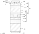
- the nitride semiconductor stack 20 has, in this order, a first n-side nitride semiconductor layer 31, a second n-side nitride semiconductor layer 32, an active layer 40, and a p-side nitride semiconductor layer 50.
- the nitride semiconductor stack 20 is, for example, epitaxially grown on a substrate 60.
- the primary surface of the nitride semiconductor stack 20 is, for example, the +c plane (i.e., the (0001) plane).
- the n-side nitride semiconductor layer 30 has one or more nitride semiconductor layers containing n-type impurities. Examples of n-type impurities include Si and Ge.
- the n-side nitride semiconductor layer 30 may have an undoped layer that is not intentionally doped with impurities.
- the n-side nitride semiconductor layer 30 includes a first n-side nitride semiconductor layer 31 and a second n-side nitride semiconductor layer 32.
- the n-side nitride semiconductor layer 30 may have other layers.
- n-side nitride semiconductor layer 30 has a third n-side nitride semiconductor layer 33, a fourth n-side nitride semiconductor layer 34, and a fifth n-side nitride semiconductor layer 35.
- the n-side nitride semiconductor layer 30 does not have to have all of these layers.
- the n-side nitride semiconductor layer 30 may have other layers.
- the first n-side nitride semiconductor layer 31 is provided at a position away from the active layer 40.
- the second n-side nitride semiconductor layer 32 is arranged between the first n-side nitride semiconductor layer 31 and the active layer 40.
- the relatively low electric field strength in the p-side nitride semiconductor layer 50 can suppress absorption losses due to p-type impurities, improving the slope efficiency of the semiconductor laser element 100.
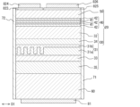
- the periodic structure provided in the diffraction grating portion 311 is a diffraction grating.
- the size of the periodic structure can be adjusted appropriately depending on the wavelength of the laser light to be obtained, the composition of the semiconductor to be used, and the like.
- the cross-sectional shape of the unevenness constituting the periodic structure along the resonance direction D1 of the optical waveguide 10 can be, for example, sawtooth, sinusoidal, rectangular, trapezoidal, inverted trapezoidal, and the like.
- the cross-sectional shape of the convex portion of the unevenness constituting the periodic structure is rectangular in FIG. 2, but is not limited to this, and may be a shape having an inclined side whose width becomes narrower as it approaches the active layer 40, such as a trapezoid.
- Each of the convex portions of the unevenness can have an upper surface. This upper surface is, for example, a surface parallel to the main surface of the active layer 40.
- Each of the concave portions of the unevenness shown in FIG. 2 has a bottom surface. This bottom surface is, for example, a surface parallel to the main surface of the active layer 40.
- Each concave portion of the unevenness may have a shape that does not have a bottom surface, such as a U-shape or a V-shape.
- the period (pitch) of the projections and recesses that make up the periodic structure can be determined by the wavelength to be oscillated and the effective refractive index.
- the projections and recesses pitch (one period) can be, for example, 40 nm or more and 140 nm or less.
- the widths of the projections and recesses in the direction along the resonance direction D1 of the optical waveguide 10 may be the same or different.
- the widths can be 120 nm or more and 420 nm or less for third-order diffraction, and 400 nm or more and 2000 nm or less for tenth-order diffraction or higher. It is preferable that the width of one of the projections and recesses is in the range of 1/2 to 2 times the width of the other.
- the height of the unevenness constituting the periodic structure is the shortest distance between a line parallel to the main surface of the active layer 40 that passes through the part of the unevenness closest to the active layer 40 and a line parallel to the main surface of the active layer 40 that passes through the part of the unevenness farthest from the active layer 40.
- TEM transmission electron microscope
- STEM scanning transmission electron microscope
- the diffraction grating portion 311 has a plurality of first portions and a plurality of second portions having a refractive index higher than that of the first portions.
- the periodic structure is formed by arranging the plurality of first portions and the plurality of second portions alternately along the resonance direction D1.
- the first semiconductor portion 31a can be obtained, for example, by forming a first semiconductor layer that will become the first semiconductor portion 31a, and then removing a portion of the first semiconductor layer by dry etching or the like. If the first semiconductor layer is removed down to its underside during the partial removal, a first semiconductor portion consisting of only multiple first portions with no common portion can be formed. If the removal is performed to a depth that does not reach the underside of the first semiconductor layer, taking into account the accuracy of the removal depth, a first semiconductor portion 31a consisting of one common portion and multiple first portions can be formed.
- the n-type impurity concentration of the first semiconductor portion 31a may be 1 ⁇ 10 17 /cm 3 or more and 1 ⁇ 10 20 /cm 3 or less, or may be below the detection limit.
- the n-type impurity concentration of the first semiconductor portion 31a may be greater than the n-type impurity concentration of the second semiconductor portion 31b.
- the concentration of impurities other than the n-type impurity in the second semiconductor portion 31b may be below the detection limit.
- the second semiconductor portion 31b is preferably made of GaN, which can reduce the possibility of a gap occurring between the second semiconductor portion 31b and the first semiconductor portion 31a. In FIG.
- the upper surface of the second semiconductor portion 31b is at the same height from the diffraction grating portion 311 to the non-diffraction grating portion 312, but this is not limited to this.
- the upper surface of the second semiconductor portion 31b of the diffraction grating portion 311 in which a recess is provided in the first semiconductor portion 31a may be lower than the upper surface of the second semiconductor portion 31b of the non-diffraction grating portion 312.
- the first semiconductor part 31a has multiple concave shapes recessed in a direction away from the active layer 40.
- the portions of the first semiconductor part 31a that sandwich the multiple concave shapes along the resonance direction D1 are either the first part or the second part.
- the multiple concave shapes are filled with the second semiconductor part 31b, and the portion that fills the multiple concave shapes is the other of the first part or the second part.
- the first semiconductor part 31a may have multiple convex shapes protruding toward the active layer 40. In this case, the multiple convex parts of the first semiconductor part 31a are either the first part or the second part, and the portions of the second semiconductor part 31b that sandwich the multiple convex shapes along the resonance direction D1 are the other of the first part or the second part.
- the concave or convex shape can be easily formed stably because at least one of the two ends in the vertical direction D2 of the concave or convex part of the first semiconductor part 31a is located inside the nitride semiconductor stack 20. This is because the strength of the first semiconductor part 31a can be expected to improve as the width of the concave or convex shape in the vertical direction D2 becomes narrower.
- the concave or convex shape is a shape in which both ends of the concave or convex shape in the vertical direction D2 are located inside the nitride semiconductor stack 20.
- the formation of the first semiconductor part 31a having a plurality of concave shapes can shorten the formation time of the periodic structure compared to the formation of the first semiconductor part 31a having a plurality of convex shapes.
- forming the first semiconductor part 31a with multiple concave shapes is expected to improve the strength of the first semiconductor part 31a compared to forming the first semiconductor part 31a with multiple convex shapes.
- the first portion is made of a nitride semiconductor containing Ga
- the second portion is made of a nitride semiconductor containing In and Ga.
- the first portion is made of GaN
- the second portion is made of In x Ga 1-x N (0 ⁇ X ⁇ 1).
- the In composition ratio of the second portion can be 0.001 ⁇ X ⁇ 0.1.
- an n-side cladding layer can be provided as a layer separate from the first n-side nitride semiconductor layer 31, and the first n-side nitride semiconductor layer 31 can be disposed between the n-side cladding layer and the active layer 40. This can reduce the threshold current and improve the optical confinement.
- the first semiconductor portion 31a includes a plurality of second portions
- the second semiconductor portion 31b includes a plurality of first portions. This can fill the unevenness of the first semiconductor portion 31a with the second semiconductor portion 31b, thereby reducing the probability of a gap occurring between the first portion and the second portion.
- the change in contrast may be more gradual at the bottom of the recess of the first semiconductor portion 31 a than at the side surface.
- the Z-contrast image is a contrast image based on atomic weight.
- the average refractive index of the periodic structure provided in the diffraction grating portion 311 can be the average value of the refractive index in the resonance direction D1 of the minimum unit of periodic repetition constituting the periodic structure.
- the minimum unit of periodic repetition constituting the periodic structure is one first portion and one second portion
- the average refractive index n ave of the periodic structure provided in the diffraction grating portion 311 is expressed by the following formula (1).
- n ave ⁇ (n 1 ⁇ t 1 ) + (n 2 ⁇ t 2 ) ⁇ / (t 1 + t 2 ) (1)
- n1 is the refractive index of the first portion
- n2 is the refractive index of the second portion
- t1 is the length of one first portion in the resonance direction D1
- t2 is the length of one second portion in the resonance direction D1.
- the refractive index is the refractive index at the peak wavelength of the laser light oscillated by the semiconductor laser element 100.
- the refractive index value of each material may be a known refractive index value of each material.
- the refractive index of a semiconductor can be calculated from the composition ratio of the semiconductor.
- the distance from the periodic structure provided in the diffraction grating portion 311 of the first n-side nitride semiconductor layer 31 to the well layer 41 may be within these numerical ranges, and the distance from the periodic structure to the active layer 40 may be within these numerical ranges.
- the distance from the periodic structure provided in the diffraction grating portion 311 to the well layer 41 (n-side well layer) may be 320 nm or more and 800 nm or less, or 400 nm or more and 800 nm or less.
- the thickness of the periodic structure i.e., the length of the periodic structure in a direction perpendicular to the main surface of the active layer 40, is equal to or smaller than the thickness of the first n-side nitride semiconductor layer 31.
- the difference between the thickness of the first n-side nitride semiconductor layer 31 and the thickness of the periodic structure can be 0 nm or more and 1000 nm or less.
- the second n-side nitride semiconductor layer 32 is preferably a nitride semiconductor layer containing In and Ga.
- the thickness of the second n-side nitride semiconductor layer 32 is preferably greater than the thickness of the n-side barrier layer described below.
- the third n-side nitride semiconductor layer 33 has a refractive index between the refractive index of the n-side cladding layer and the average refractive index of the periodic structure of the diffraction grating portion 311 of the first n-side nitride semiconductor layer 31.
- the refractive index of the third n-side nitride semiconductor layer 33 is higher than the refractive index of the n-side cladding layer and lower than the average refractive index of the periodic structure of the diffraction grating portion 311.
- the fourth n-side nitride semiconductor layer 34 is disposed between the second n-side nitride semiconductor layer 32 and the first n-side nitride semiconductor layer 31.
- the refractive index of the fourth n-side nitride semiconductor layer 34 may be lower than the refractive index of the second n-side nitride semiconductor layer 32 and higher than the average refractive index of the periodic structure of the diffraction grating portion 311 of the first n-side nitride semiconductor layer 31.
- the fourth n-side nitride semiconductor layer 34 may not be provided, and instead the thickness of the common portion of the second semiconductor portion 31b may be set to 50 nm or more. This can improve the light confinement in the active layer 40.
- the thickness of the common portion of the second semiconductor portion 31b may be 300 nm or less.
- the fourth n-side nitride semiconductor layer 34 is, for example, an InGaN layer.
- the fourth n-side nitride semiconductor layer 34 may contain n-type impurities.
- the thickness of the fourth n-side nitride semiconductor layer 34 may be 1 nm or more and 500 nm or less.
- the fifth n-side nitride semiconductor layer 35 is disposed on the opposite side of the first n-side nitride semiconductor layer 31 to the active layer 40.
- the fifth n-side nitride semiconductor layer 35 is disposed between the first n-side nitride semiconductor layer 31 and the substrate 60.
- the fifth n-side nitride semiconductor layer 35 is, for example, an n-side cladding layer.
- the fifth n-side nitride semiconductor layer 35 is, for example, a layer having the largest band gap energy among the n-side nitride semiconductor layer 30.
- the fifth n-side nitride semiconductor layer 35 is, for example, an AlGaN layer containing n-type impurities.
- the diffraction grating portion 311 and the non-diffraction grating portion 312 are formed in the first n-side nitride semiconductor layer 31. This allows the semiconductor laser element 100 to have a structure in which the regrowth interface is only in the first n-side nitride semiconductor layer 31. Because the electric field strength of the first n-side nitride semiconductor layer 31 when the semiconductor laser element 100 is in operation is smaller than the electric field strength of the active layer 40, this arrangement can reduce the effects of impurities introduced during regrowth.
- the upper surface of the first n-side nitride semiconductor layer 31 may be lower in the diffraction grating portion 311 than in the non-diffraction grating portion 312.
- the thickness of the layer provided on top of it is less than the step, it may be divided by the step, but even in this case, it can be said that the layer is provided from above the diffraction grating portion 311 to above the non-diffraction grating portion 312.
- the thickness of the second n-side nitride semiconductor layer 32 is greater than the thickness of the thickest layer among them. This can reduce absorption losses and/or improve light confinement to the active layer 40. Furthermore, it is preferable that the thickness of the second n-side nitride semiconductor layer 32 is greater than the total thickness of the multiple semiconductor layers located between the n-side well layer and the second n-side nitride semiconductor layer 32. This can further reduce absorption losses and/or improve light confinement to the active layer 40.
- the active layer 40 can be formed with a composition capable of emitting light with a wavelength of, for example, 400 nm or more and 600 nm or less.
- the one or more well layers 41 are made of, for example, InGaN.
- the In composition ratio of the InGaN constituting the one or more well layers 41 can be, for example, 0.05 or more and 0.50 or less.
- the In composition ratio of the InGaN constituting the one or more well layers 41 may be 0.15 or more.
- the p-side nitride semiconductor layer 50 has one or more nitride semiconductor layers containing p-type impurities. Examples of p-type impurities include Mg.
- the p-side nitride semiconductor layer 50 may have an undoped layer that is not intentionally doped with impurities.
- the p-side nitride semiconductor layer 50 may have a contact layer.
- the p-side nitride semiconductor layer 50 may have one or more of a p-side optical guide layer, an electron blocking layer, and a p-side cladding layer.
- the p-side nitride semiconductor layer 50 may have all of these layers, or may have layers other than these layers.
- the activation rate of p-type impurities is lower than that of n-type impurities.
- the p-type impurity concentration in the p-side nitride semiconductor layer 50 tends to be higher than the n-type impurity concentration in the n-side nitride semiconductor layer 30.
- the maximum value of the p-type impurity concentration in the p-side nitride semiconductor layer 50 is higher than the maximum value of the n-type impurity concentration in the n-side nitride semiconductor layer 30.
- the semiconductor laser element 100 has an n-electrode 81.
- the n-electrode 81 is provided on the lower surface of the substrate 60.
- Examples of materials for the n-electrode 81 include a single layer film or a multilayer film of a conductive oxide containing at least one selected from metals or alloys such as Ni, Rh, Cr, Au, W, Pt, Ti, and Al, and Zn, In, and Sn.
- the conductive oxide include indium tin oxide (ITO), indium zinc oxide (IZO), and gallium-doped zinc oxide (GZO).
- the semiconductor laser element 100 has a p-electrode 82.
- the p-electrode 82 is provided in contact with a part of the p-side nitride semiconductor layer 50.
- the p-electrode 82 is provided in contact with, for example, the upper surface of the ridge 20c.
- the p-electrode 82 may have a pad electrode.
- materials for the p-electrode 82 include a single layer or multilayer film of a conductive oxide containing at least one selected from metals or alloys such as Ni, Rh, Cr, Au, W, Pt, Ti, and Al, and Zn, In, and Sn.
- the conductive oxide include ITO, IZO, and GZO.
- the semiconductor laser element 100 can have a first p electrode 821 and a second p electrode 822 as the p electrode 82.
- the first p electrode 821 is provided on the upper surface of the p-side nitride semiconductor layer 50, above the diffraction grating portion 311.
- the second p electrode 822 is provided on the upper surface of the p-side nitride semiconductor layer 50, above the non-diffraction grating portion 312, and away from the first p electrode 821.
- the current passed through the non-diffraction grating portion 312 is set to a magnitude according to the desired optical output
- the current passed through the diffraction grating portion 311 is set to a magnitude that reduces optical absorption in the diffraction grating portion 311.
- the well layer 41 When no current is passed through the diffraction grating portion 311, the well layer 41 becomes a highly absorbing layer, causing a rising kink, but this can be suppressed by passing a current through the diffraction grating portion 311.
- the current passed through the diffraction grating portion 311 may be smaller than the current passed through the non-diffraction grating portion 312.
- the wavelength may be tuned by changing the magnitude of the current passed through the diffraction grating portion 311.
- the first p-electrode 821 is disposed away from the second p-electrode 822.
- FIG. 5 is a schematic diagram for explaining the first contact layer 511 and the second contact layer 512.
- the p-side nitride semiconductor layer 50 may have, as contact layers, the first contact layer 511 in contact with the lower surface of the first p electrode 821 and the second contact layer 512 in contact with the lower surface of the second p electrode 822. This makes it possible to more reliably control the diffraction grating portion 311 and the non-diffraction grating portion 312 independently.
- the first contact layer 511 is disposed away from the second contact layer 512.
- the first p-electrode 821 may have a first conductive oxide film 823 provided on the upper surface of the p-side nitride semiconductor layer 50 and a first metal film 824 arranged above the first conductive oxide film 823.
- the second p-electrode 822 may have a second conductive oxide film 825 provided on the upper surface of the p-side nitride semiconductor layer 50 and a second metal film 826 arranged above the second conductive oxide film 825.
- the light emitting side end of the first conductive oxide film 823 and the light reflecting side end of the second conductive oxide film 825 are located between the light emitting side end of the first metal film 824 and the light reflecting side end of the second metal film 826.
- the end of the first conductive oxide film 823 on the first end face 20a side and the end of the second conductive oxide film 825 on the second end face 20b side are located between the end of the first metal film 824 on the first end face 20a side and the end of the second metal film 826 on the second end face 20b side.
- the end closer to the first end face 20a of both ends in the resonance direction of the optical waveguide is the end on the first end face 20a side
- the end closer to the second end face 20b is the end on the second end face 20b side.
- the end on the first end face 20a side is the end on the light emitting side
- the end on the second end face 20b side is the end on the light reflecting side.
- the end on the first end face 20a side may be the end on the light reflecting side
- the end on the second end face 20b side may be the end on the light emitting side. It is more preferable that both the end on the first end face 20a side of the first conductive oxide film 823 and the end on the second end face 20b side of the second conductive oxide film 825 are located between the end on the first end face 20a side of the first metal film 824 and the end on the second end face 20b side of the second metal film 826.
- both the end on the light emitting side of the first conductive oxide film 823 and the end on the light reflecting side of the second conductive oxide film 825 are located between the end on the light emitting side of the first metal film 824 and the end on the light reflecting side of the second metal film 826.
- No current is injected between the first p electrode 821 and the second p electrode 822, and the greater the distance between them, the greater the light absorption.
- the distance from the first conductive oxide film 823 to the second conductive oxide film 825 can be, for example, 1 ⁇ m or more and 30 ⁇ m or less.
- the end of the first conductive oxide film 823 on the first end surface 20a side protrudes from the end of the first metal film 824 on the first end surface 20a side toward the second p electrode 822.
- the end of the first conductive oxide film 823 on the light emission side protrudes from the end of the first metal film 824 on the light emission side toward the second p electrode 822.
- the distance from the first end surface 20a to the first conductive oxide film 823 is smaller than the distance from the first end surface 20a to the first metal film 824.
- the end of the second conductive oxide film 825 on the second end surface 20b side protrudes from the end of the second metal film 826 on the second end surface 20b side toward the first p electrode 821.
- the end of the second conductive oxide film 825 on the light reflection side protrudes from the end of the second metal film 826 on the light reflection side toward the first p electrode 821.
- the distance from the second end face 20b to the second conductive oxide film 825 is smaller than the distance from the second end face 20b to the second metal film 826.
- the first conductive oxide film 823 and the second conductive oxide film 825 have at least a portion that overlaps with the optical waveguide in the top view.
- the first conductive oxide film 823 and the second conductive oxide film 825 have at least a portion that overlaps with the ridge 20c.
- the portions of the first conductive oxide film 823 and the second conductive oxide film 825 that protrude from the first metal film 824 and the second metal film 826 at least partially overlap with the optical waveguide in the top view.
- both the first p electrode 821 and the second p electrode 822 have a conductive oxide film, but a structure in which only one of them has a conductive oxide film may be used.
- the semiconductor laser element 100 may have a first protective film 71 and a second protective film 72.
- the first protective film 71 is provided on the first end face 20a of the nitride semiconductor stack 20.
- the second protective film 72 is provided on the second end face 20b of the nitride semiconductor stack 20.
- One or both of the first protective film 71 and the second protective film 72 may not be provided.
- Each of the first protective film 71 and the second protective film 72 can have one or more dielectric films.
- the reflectance of the first protective film 71 may be 18% or more, and 30% or more is more preferable.
- the semiconductor laser element 100 is an element that emits laser light with a peak wavelength of 500 nm or more
- the gain inside the resonator tends to be lower than when the element emits laser light with a peak wavelength of less than 500 nm.
- the reflectance of the first protective film 71 is 30% or more and less than the reflectance of the second protective film 72. This makes it possible to reduce the threshold current.
- the reflectance of the second protective film 72 is higher than the reflectance of the first protective film 71.
- the reflectance of the second protective film 72 can be, for example, 95% or more, and may be 98% or more.
- the reflectance of the second protective film 72 can be, for example, 100% or less.
- the reflectance of the second protective film 72 may be 100%.
- the reflectance of the first protective film 71 and the reflectance of the second protective film 72 refer to the reflectance at the peak wavelength of the laser light oscillated by the semiconductor laser element 100.
- the second end face 20b which is the end face on the side where the diffraction grating portion 311 is located, may be used as the light emitting end face.
- the reflectance of the second protective film 72 is lower than that of the first protective film 71.
- the reflectance of the first protective film 71 may be, for example, 85% or more, or may be 90% or more.
- the reflectance of the first protective film 71 may be, for example, 100% or less.
- the second protective film 72 may be an AR coating.
- the reflectance of the second protective film 72 may be 0.1% or more, or may be 5% or more.
- the second protective film 72 does not need to be provided. By using the second end face 20b as the light emitting end face, the second protective film 72 can be made unnecessary.
- the light output can be stabilized. This is because an effective refractive index difference occurs at the concave and convex portions of the diffraction grating portion 311, and an effective reflectance in the laser diode is obtained.
- a diffraction grating section 311 With a length in the resonance direction D1 of 100 ⁇ m or more, it is possible to obtain sufficient reflectance required for laser oscillation even without the second protective film 72.
- a Si-containing Al 0.016 Ga 0.984 N layer was grown to a thickness of 1.8 ⁇ m on a c-plane GaN substrate (substrate 60 ).
- a Si-containing Al 0.08 Ga 0.92 N layer was grown to a thickness of 200 nm.
- a Si-containing In 0.04 Ga 0.96 N layer was grown to a thickness of 150 nm.
- a Si-containing Al 0.08 Ga 0.92 N layer (n-side cladding layer) was grown to a thickness of 650 nm.
- a Si-containing GaN layer was grown to a thickness of 100 nm.
- a Si-containing In 0.03 Ga 0.97 N layer (a first semiconductor layer that becomes the first semiconductor portion 31a) was grown to a thickness of 150 nm.
- the epitaxial wafer on which the above layers were formed was removed from the MOCVD apparatus, and a periodic uneven shape (periodic structure) was created using an electron beam lithography apparatus, reactive ion etching (RIE), and sputtering.
- the depth of the recess was 83 nm
- the width of the recess was 39 nm
- the diffraction grating period ⁇ one period of the unevenness
- the periodic structure was formed only in the diffraction grating portion 311.
- the length of the diffraction grating portion 311 along the resonance direction D1 was 300 ⁇ m
- the length of the non-diffraction grating portion 312 along the resonance direction D1 was 500 ⁇ m.
- n-side nitride semiconductor layer 32 an undoped In 0.03 Ga 0.97 N layer (second n-side nitride semiconductor layer 32 ) was grown to a thickness of 240 nm.
- the n-side nitride semiconductor layer 30 is made up of layers from the Si-containing Al 0.016 Ga 0.984 N layer to this layer.
- an active layer 40 was grown including, in this order, an n-side barrier layer (barrier layer 42) consisting of three layers: a 1 nm-thick Si-doped GaN layer, an 8 nm-thick Si-doped In0.05Ga0.95N layer, and a 1 nm-thick Si-doped GaN layer, an undoped In0.25Ga0.75N layer (well layer 41), a 3.3 nm-thick undoped GaN layer (barrier layer 42), an undoped In0.25Ga0.75N layer (well layer 41), and a 2.3 nm-thick undoped GaN layer (barrier layer 42).
- an n-side barrier layer consisting of three layers: a 1 nm-thick Si-doped GaN layer, an 8 nm-thick Si-doped In0.05Ga0.95N layer, and a 1 nm-thick Si-doped GaN layer, an undoped In0.25Ga
- the semiconductor laser element 100 was obtained by forming a first protective film 71 on the first end face 20a and a second protective film 72 on the second end face 20b.
- the reflectance of the first protective film 71 was 90%, and the reflectance of the second protective film 72 was 97%. That is, in the semiconductor laser element 100 of Example 1, the first end face 20a is the light-emitting end face.
- the semiconductor laser element 100 had a ridge width of 2 ⁇ m, a cavity length of 800 ⁇ m, and an element width of 200 ⁇ m.
- the semiconductor laser element 100 of Example 1 when a voltage was applied between the n-electrode 81 and the second metal film 826 provided on the non-diffraction grating portion 312 and a current of 500 mA was injected, the semiconductor laser element 100 of Example 1 oscillated a laser beam with a peak wavelength of about 528 nm. No voltage was applied between the n-electrode 81 and the first metal film 824 provided on the diffraction grating portion 311.
- the spectrum of the semiconductor laser element 100 of Example 1 is shown in FIG. 6.
- the horizontal axis of FIG. 6 is the wavelength.
- the light intensity as an intensity ratio (unit: dB), and the side mode suppression ratio (SMSR) was estimated with the largest peak set to 0 dB.
- the side mode suppression ratio of the semiconductor laser element 100 of Example 1 was greater than 20 dB.
- the spectral width of the semiconductor laser element 100 of Example 1 was about 3 pm. Since the resolution of the spectrum analyzer used was about 3 pm, it can be said that an extremely narrow spectral width was obtained.
- the spacing between adjacent longitudinal modes calculated from the effective refractive index and cavity length is about 0.06 nm to 0.07 nm, but no large peaks thought to be due to adjacent longitudinal modes are observed, and the side mode suppression ratio is at least greater than 20 dB, so it can be said that the semiconductor laser element 100 of Example 1 oscillated in a single longitudinal mode.
- Example 2 As Example 2, a semiconductor laser element similar to that of Example 1 was fabricated, except that the second protective film 72 was not provided and the reflectance of the first protective film 71 was set to 90%. That is, in the semiconductor laser element of Example 2, the second end facet 20b is the light-emitting end facet.
- the five peaks in FIG. 8 are the spectra when the current flowing between the n-electrode 81 and the first metal film 824 was set to 100 mA, 150 mA, 200 mA, 250 mA, and 300 mA, in order from the left.
- the side mode suppression ratio of the semiconductor laser element of Example 2 was greater than 20 dB.
- the semiconductor laser element 100 of Example 2 oscillated laser light with a peak wavelength of about 528.5 nm by injecting a current of 100 mA between the n-electrode 81 and the first metal film 824.
- the semiconductor laser element according to any one of items 1 to 6, wherein the periodic structure of the diffraction grating portion is configured by alternately arranging the plurality of first portions and the plurality of second portions along the resonance direction.
- the nitride semiconductor stack is an n-side cladding layer disposed on a side of the first n-side nitride semiconductor layer opposite to the active layer; 8.
- the semiconductor laser element according to any one of items 1 to 7, further comprising: a third n-side nitride semiconductor layer disposed between the n-side cladding layer and the first n-side nitride semiconductor layer, the third n-side nitride semiconductor layer having a refractive index between a refractive index of the n-side cladding layer and an average refractive index of the periodic structure of the diffraction grating portion of the first n-side nitride semiconductor layer.
- Optical waveguide 20 Nitride semiconductor laminate 20a First end face 20b Second end face 20c Ridge 30 n-side nitride semiconductor layer 31 First n-side nitride semiconductor layer 31a First semiconductor portion 31b Second semiconductor portion 311 Diffraction grating portion 312 Non-diffraction grating portion 32 Second n-side nitride semiconductor layer 33 Third n-side nitride semiconductor layer 34 Fourth n-side nitride semiconductor layer 35 Fifth n-side nitride semiconductor layer 40 Active layer 41 Well layer 42 Barrier layer 50 p-side nitride semiconductor layer 511 First contact layer 512 Second contact layer 60 Substrate 71 First protective film 72 Second protective film 73 Insulating film 81 n-electrode 82 p-electrode 821 First p-electrode 822 Second p-electrode 823 First conductive oxide film 824 First metal film 825 Second conductive oxide film 826 Second metal film 100 Semiconductor laser element
Landscapes
- Physics & Mathematics (AREA)
- Condensed Matter Physics & Semiconductors (AREA)
- General Physics & Mathematics (AREA)
- Electromagnetism (AREA)
- Optics & Photonics (AREA)
- Semiconductor Lasers (AREA)
Priority Applications (5)
| Application Number | Priority Date | Filing Date | Title |
|---|---|---|---|
| JP2024567408A JP7667524B2 (ja) | 2022-12-26 | 2023-12-11 | 半導体レーザ素子 |
| DE112023005425.8T DE112023005425T5 (de) | 2022-12-26 | 2023-12-11 | Halbleiterlaserelement |
| KR1020257006180A KR20250129608A (ko) | 2022-12-26 | 2023-12-11 | 반도체 레이저 소자 |
| CN202380075105.0A CN120129999A (zh) | 2022-12-26 | 2023-12-11 | 半导体激光元件 |
| JP2025064030A JP2025096459A (ja) | 2022-12-26 | 2025-04-09 | 半導体レーザ素子 |
Applications Claiming Priority (2)
| Application Number | Priority Date | Filing Date | Title |
|---|---|---|---|
| JP2022-208079 | 2022-12-26 | ||
| JP2022208079 | 2022-12-26 |
Publications (1)
| Publication Number | Publication Date |
|---|---|
| WO2024142875A1 true WO2024142875A1 (ja) | 2024-07-04 |
Family
ID=91717564
Family Applications (1)
| Application Number | Title | Priority Date | Filing Date |
|---|---|---|---|
| PCT/JP2023/044165 Ceased WO2024142875A1 (ja) | 2022-12-26 | 2023-12-11 | 半導体レーザ素子 |
Country Status (5)
| Country | Link |
|---|---|
| JP (2) | JP7667524B2 (https=) |
| KR (1) | KR20250129608A (https=) |
| CN (1) | CN120129999A (https=) |
| DE (1) | DE112023005425T5 (https=) |
| WO (1) | WO2024142875A1 (https=) |
Citations (7)
| Publication number | Priority date | Publication date | Assignee | Title |
|---|---|---|---|---|
| JPH11274642A (ja) * | 1998-03-19 | 1999-10-08 | Toshiba Corp | 半導体発光素子及びその製造方法 |
| US20020181532A1 (en) * | 2001-05-31 | 2002-12-05 | Sang-Wan Ryu | Multi-wavelength semiconductor laser array and method for fabricating the same |
| US20110090932A1 (en) * | 2008-12-04 | 2011-04-21 | Kyung Hyun Park | Multiple distributed feedback laser devices |
| JP2013505586A (ja) * | 2009-09-17 | 2013-02-14 | ソラア インコーポレーテッド | {20−21}ガリウム及び窒素含有基板上の低電圧レーザダイオード |
| WO2017138668A1 (ja) * | 2016-02-12 | 2017-08-17 | 古河電気工業株式会社 | 半導体レーザ素子、回折格子構造、および回折格子 |
| JP2018037495A (ja) * | 2016-08-30 | 2018-03-08 | パナソニックIpマネジメント株式会社 | 窒化物半導体レーザ素子 |
| US10277008B1 (en) * | 2017-12-15 | 2019-04-30 | Electronics And Telecommunications Research Institute | Tunable laser device and method for manufacturing the same |
Family Cites Families (1)
| Publication number | Priority date | Publication date | Assignee | Title |
|---|---|---|---|---|
| JP5534826B2 (ja) | 2010-01-19 | 2014-07-02 | 日本オクラロ株式会社 | 半導体光素子、光送信モジュール、光送受信モジュール、光伝送装置、及び、それらの製造方法 |
-
2023
- 2023-12-11 JP JP2024567408A patent/JP7667524B2/ja active Active
- 2023-12-11 DE DE112023005425.8T patent/DE112023005425T5/de active Pending
- 2023-12-11 WO PCT/JP2023/044165 patent/WO2024142875A1/ja not_active Ceased
- 2023-12-11 CN CN202380075105.0A patent/CN120129999A/zh active Pending
- 2023-12-11 KR KR1020257006180A patent/KR20250129608A/ko active Pending
-
2025
- 2025-04-09 JP JP2025064030A patent/JP2025096459A/ja active Pending
Patent Citations (7)
| Publication number | Priority date | Publication date | Assignee | Title |
|---|---|---|---|---|
| JPH11274642A (ja) * | 1998-03-19 | 1999-10-08 | Toshiba Corp | 半導体発光素子及びその製造方法 |
| US20020181532A1 (en) * | 2001-05-31 | 2002-12-05 | Sang-Wan Ryu | Multi-wavelength semiconductor laser array and method for fabricating the same |
| US20110090932A1 (en) * | 2008-12-04 | 2011-04-21 | Kyung Hyun Park | Multiple distributed feedback laser devices |
| JP2013505586A (ja) * | 2009-09-17 | 2013-02-14 | ソラア インコーポレーテッド | {20−21}ガリウム及び窒素含有基板上の低電圧レーザダイオード |
| WO2017138668A1 (ja) * | 2016-02-12 | 2017-08-17 | 古河電気工業株式会社 | 半導体レーザ素子、回折格子構造、および回折格子 |
| JP2018037495A (ja) * | 2016-08-30 | 2018-03-08 | パナソニックIpマネジメント株式会社 | 窒化物半導体レーザ素子 |
| US10277008B1 (en) * | 2017-12-15 | 2019-04-30 | Electronics And Telecommunications Research Institute | Tunable laser device and method for manufacturing the same |
Also Published As
| Publication number | Publication date |
|---|---|
| JP2025096459A (ja) | 2025-06-26 |
| JPWO2024142875A1 (https=) | 2024-07-04 |
| JP7667524B2 (ja) | 2025-04-23 |
| DE112023005425T5 (de) | 2025-10-09 |
| KR20250129608A (ko) | 2025-08-29 |
| CN120129999A (zh) | 2025-06-10 |
Similar Documents
| Publication | Publication Date | Title |
|---|---|---|
| US7015565B2 (en) | Gallium nitride type semiconductor laser device | |
| US6855570B2 (en) | Compound semiconductor laser | |
| US8575626B2 (en) | Bi-section semiconductor laser device, method for manufacturing the same, and method for driving the same | |
| JP7617458B2 (ja) | 半導体レーザ素子 | |
| US7781796B2 (en) | Nitride semiconductor laser element | |
| JP5138023B2 (ja) | 半導体レーザ素子 | |
| JPH10126010A (ja) | 半導体レーザ装置の製造方法 | |
| US20120076165A1 (en) | Asymmetrically cladded laser diode | |
| JPWO2009078482A1 (ja) | 半導体発光素子 | |
| JP2000349397A (ja) | 半導体発光素子 | |
| JP2012151210A (ja) | 半導体レーザ素子 | |
| US7804882B2 (en) | Nitride semiconductor laser element | |
| CN102804416A (zh) | 半导体发光元件及其制造方法 | |
| JP7667524B2 (ja) | 半導体レーザ素子 | |
| JP3933637B2 (ja) | 窒化ガリウム系半導体レーザ素子 | |
| JP4163321B2 (ja) | 半導体発光装置 | |
| JP5536132B2 (ja) | 半導体レーザ素子 | |
| US20240332911A1 (en) | Semiconductor laser element | |
| JP3925066B2 (ja) | 窒化物半導体レーザ素子 | |
| JP2001057458A (ja) | 半導体発光装置 | |
| JP2006054426A (ja) | 自励発振型半導体レーザ装置 | |
| JP2000353861A (ja) | Iii−v族半導体発光デバイスの製造方法 | |
| JP2006140387A (ja) | 窒化物半導体レ−ザ及びその製造方法 | |
| JP5304428B2 (ja) | 半導体レーザ | |
| WO2005104318A1 (ja) | 半導体発光装置 |
Legal Events
| Date | Code | Title | Description |
|---|---|---|---|
| 121 | Ep: the epo has been informed by wipo that ep was designated in this application |
Ref document number: 23911656 Country of ref document: EP Kind code of ref document: A1 |
|
| WWE | Wipo information: entry into national phase |
Ref document number: 2024567408 Country of ref document: JP |
|
| WWE | Wipo information: entry into national phase |
Ref document number: 202380075105.0 Country of ref document: CN |
|
| WWP | Wipo information: published in national office |
Ref document number: 202380075105.0 Country of ref document: CN |
|
| WWE | Wipo information: entry into national phase |
Ref document number: 112023005425 Country of ref document: DE |
|
| WWP | Wipo information: published in national office |
Ref document number: 1020257006180 Country of ref document: KR |
|
| WWP | Wipo information: published in national office |
Ref document number: 112023005425 Country of ref document: DE |
|
| 122 | Ep: pct application non-entry in european phase |
Ref document number: 23911656 Country of ref document: EP Kind code of ref document: A1 |