WO2024142324A1 - 電力変換装置、モータ駆動装置及び冷凍サイクル適用機器 - Google Patents
電力変換装置、モータ駆動装置及び冷凍サイクル適用機器 Download PDFInfo
- Publication number
- WO2024142324A1 WO2024142324A1 PCT/JP2022/048393 JP2022048393W WO2024142324A1 WO 2024142324 A1 WO2024142324 A1 WO 2024142324A1 JP 2022048393 W JP2022048393 W JP 2022048393W WO 2024142324 A1 WO2024142324 A1 WO 2024142324A1
- Authority
- WO
- WIPO (PCT)
- Prior art keywords
- capacitor
- motor
- voltage
- control
- conversion device
- Prior art date
- Legal status (The legal status is an assumption and is not a legal conclusion. Google has not performed a legal analysis and makes no representation as to the accuracy of the status listed.)
- Ceased
Links
Images





Classifications
-
- H—ELECTRICITY
- H02—GENERATION; CONVERSION OR DISTRIBUTION OF ELECTRIC POWER
- H02M—APPARATUS FOR CONVERSION BETWEEN AC AND AC, BETWEEN AC AND DC, OR BETWEEN DC AND DC, AND FOR USE WITH MAINS OR SIMILAR POWER SUPPLY SYSTEMS; CONVERSION OF DC OR AC INPUT POWER INTO SURGE OUTPUT POWER; CONTROL OR REGULATION THEREOF
- H02M7/00—Conversion of AC power input into DC power output; Conversion of DC power input into AC power output
- H02M7/42—Conversion of DC power input into AC power output without possibility of reversal
- H02M7/44—Conversion of DC power input into AC power output without possibility of reversal by static converters
- H02M7/48—Conversion of DC power input into AC power output without possibility of reversal by static converters using discharge tubes with control electrode or semiconductor devices with control electrode
Definitions
- Patent Document 1 describes a power conversion device that performs load pulsation compensation control to reduce motor vibration and power supply pulsation compensation control to suppress the charge/discharge current of a capacitor while prioritizing constant current load control to control the rotation speed of the motor.
- load pulsation compensation control By implementing power supply pulsation compensation control, the ripple voltage contained in the capacitor voltage can be suppressed, allowing the use of a capacitor with a small capacity. Therefore, by using the technology of Patent Document 1, it is possible to suppress the deterioration of the capacitor while suppressing the increase in size of the device.
- the present disclosure has been made in consideration of the above, and aims to obtain a power conversion device that can suppress capacitor degradation even when power supply pulsation compensation control is not operating as expected.
- the power conversion device includes a rectifier that rectifies a first AC power supplied from a commercial power source, a capacitor connected to the output terminal of the rectifier, an inverter connected to both ends of the capacitor to generate a second AC power and output it to a motor, and a control unit that controls the operation of the inverter.
- the control unit distributes the torque current command for load pulsation compensation control that suppresses motor vibration and the torque current command for power supply pulsation compensation control that suppresses the capacitor current, which is the charge/discharge current of the capacitor, so that they can be appropriately set, while prioritizing a torque current command for constant current load control that controls the drive frequency of the motor within a settable torque current range.
- the control unit detects or calculates a physical quantity that has the same characteristics as the capacitor current, and controls to lower the drive frequency of the motor or stop the drive of the motor when the physical quantity exceeds a protection threshold.
- the power conversion device disclosed herein has the effect of suppressing capacitor degradation even when the power supply pulsation compensation control is not operating as expected.
- FIG. 1 is a block diagram showing an example of a hardware configuration for implementing the functions of a control unit according to a first embodiment
- FIG. 1 is a diagram showing a configuration example of a power conversion device according to a second embodiment
- FIG. 11 is a block diagram showing a configuration example of a control unit included in a power conversion device according to a second embodiment.
- FIG. 11 is a block diagram showing a configuration example of a capacitor voltage processing unit included in a control unit according to a second embodiment;
- FIG. 11 is a diagram for explaining the operation of a main part of a capacitor voltage processing unit according to a second embodiment.
- FIG. 13 is a diagram showing a configuration example of a refrigeration cycle application device according to a third embodiment.
- Embodiment 1. 1 is a diagram showing an example of the configuration of a power conversion device 1 according to a first embodiment.
- the power conversion device 1 is connected to a commercial power source 110 and a compressor 315.
- the power conversion device 1 converts a first AC power having a power source voltage Vs supplied from the commercial power source 110 into a second AC power having a desired amplitude and frequency, and supplies the second AC power to the compressor 315.
- the commercial power source 110 is an example of an AC power source
- the compressor 315 is an example of a device connected to the power conversion device 1.
- a motor 314 is mounted on the compressor 315.
- the power conversion device 1 and the motor 314 provided in the compressor 315 constitute a motor drive device 2.
- the power conversion device 1 includes a reactor 120, a rectifier 130, a smoothing unit 200, a first voltage detection unit 500, a second voltage detection unit 501, an inverter 310, current detection units 313a and 313b, and a control unit 400.
- the first voltage detection unit 500 detects the capacitor voltage Vdc , which is the voltage across the capacitor 210, and converts the detected voltage value into a value that can be input to the control unit 400 and outputs it.
- the second voltage detection unit 501 detects the power supply voltage Vs , which is the voltage of the commercial power supply 110, and converts the detected voltage value into a value that can be input to the control unit 400 and outputs it.
- the voltage values input from the first and second voltage detection units 500, 501 are used in a form that is restored to the capacitor voltage Vdc and the power supply voltage Vs , respectively.
- a description of the part that restores the output voltages of the first and second voltage detection units 500, 501 into the capacitor voltage Vdc and the power supply voltage Vs , respectively, will be omitted. The same applies to the other detection units.
- Current detection units 313a and 313b each detect the current value of one of the three-phase currents output from inverter 310, and output the detected current value to control unit 400.
- control unit 400 can calculate the current value of the remaining one phase output from inverter 310 by acquiring the current values of two of the three-phase current values output from inverter 310.
- FIG. 1 shows a configuration in which phase currents are directly detected, a configuration in which inverter input current I2 is detected and the three-phase current values are obtained from the detected current values may also be used.
- the motor 314 mounted on the compressor 315 rotates in accordance with the amplitude and frequency of the AC power supplied from the inverter 310, and performs a compression operation.
- Examples of the compressor 315 include a single rotary compressor and a twin rotary compressor.
- the main component frequency of the load pulsation of the motor 314 is one time the mechanical angle drive frequency of the motor 314.
- the main component frequency of the load pulsation of the motor 314 is two times the mechanical angle drive frequency of the motor 314.
- the control unit 400 acquires the capacitor voltage Vdc from the first voltage detection unit 500, and extracts a ripple value obtained by removing the DC component from the capacitor voltage Vdc .
- the control unit 400 further extracts a specific frequency component of the power supply voltage Vs from the ripple value, controls the inverter 310 so as to bring the extracted specific frequency component closer to zero, and adds pulsation to the power output to the motor 314.
- the specific frequency component is a frequency component twice the frequency of the power supply voltage Vs
- the specific frequency component is a frequency component six times the frequency of the power supply voltage Vs.
- the control unit 400 controls the operation of the inverter 310 so that pulsation according to the power state of the capacitor 210 is superimposed on the drive pattern of the motor 314. This suppresses the capacitor current I3. This control is called “power supply pulsation compensation control.”
- motor 314 when a single rotary compressor is used for compressor 315, motor 314 generates a load torque pulsation that is one time the mechanical angle drive frequency of motor 314, and when a twin rotary compressor is used for compressor 315, motor 314 generates a load torque pulsation that is twice the mechanical angle drive frequency of motor 314. For this reason, when compressor 315 is driven with a constant output current from inverter 310, i.e., with a constant torque output, speed fluctuations occur due to the torque difference. Motor drive device 2 has the characteristic that speed fluctuations occur significantly in the low speed range and become smaller as the operating point moves to the high speed range.
- the control unit 400 performs power supply pulsation compensation control for compensating for power supply pulsation and load pulsation compensation control for compensating for load pulsation.
- the power supply pulsation compensation control and the load pulsation compensation control are performed together with the constant current load control for controlling the drive frequency of the motor 314.
- the control unit 400 performs control to lower the drive frequency of the motor 314 or to stop the drive of the motor 314.
- Fig. 2 is a block diagram showing an example of the configuration of the control unit 400 provided in the power conversion device 1 according to the first embodiment.
- Fig. 3 is a first diagram for explaining the operation of the main parts of the control unit 400 according to the first embodiment.
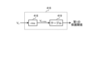
- Fig. 4 is a block diagram showing an example of the configuration of the first protection threshold generating unit 416 provided in the control unit 400 according to the first embodiment.
- Fig. 5 is a second diagram for explaining the operation of the main parts of the control unit 400 according to the first embodiment.
- Fig. 6 is a block diagram showing an example of the configuration of the capacitor voltage processing unit 417 provided in the control unit 400 according to the first embodiment.
- the control unit 400 includes a rotor position estimation unit 401, a speed control unit 402, a flux-weakening control unit 403, a current control unit 404, coordinate conversion units 405 and 406, a PWM signal generation unit 407, a subtraction unit 408, a distribution ratio multiplication unit 409, a load pulsation compensation control unit 410, an addition unit 411, a subtraction unit 412, a power supply pulsation compensation control unit 413, an addition unit 414, a first protection threshold generation unit 416, and a capacitor voltage processing unit 417.
- the addition units 411 and 414 constitute a q-axis current command generation unit 415.
- the rotor position estimator 401 estimates an estimated phase angle ⁇ est , which is the direction of the rotor magnetic poles on the dq axes, and an estimated speed ⁇ est , which is the rotor speed, for a rotor (not shown) of the motor 314, using a dq-axis voltage command vector V dq * and a dq-axis current vector i dq for driving the motor 314.
- the rotor position estimator 401 also outputs a correction torque command ⁇ * rip , which is the basis for generating a q-axis current command I qavs for load pulsation compensation control (described later), to the load pulsation compensation controller 410.
- the correction torque command ⁇ * rip can be generated, for example, by using the means or method described in Japanese Patent No. 7012901.
- the speed control unit 402 generates a q-axis current command I qsp so that the speed command ⁇ * and the estimated speed ⁇ est coincide with each other.
- the q-axis current command I qsp is a torque current command for constant current load control.
- the speed command ⁇ * is based on, for example, detected temperature information detected by a temperature sensor (not shown), set temperature information indicating a set temperature instructed from a remote control (not shown), which is an operation unit, selection information of an operation mode, and instruction information for starting and ending operation.
- the operation modes are, for example, heating, cooling, dehumidification, etc.
- the stall request output from the capacitor voltage processing unit 417 described later is "1: yes"
- the stall request takes precedence over the temperature information, instruction information, and selection information described above, and the speed command ⁇ * is controlled to be lowered.
- the speed command ⁇ * is prohibited from being increased for a while in order to prevent hunting of the speed command ⁇ * .
- An example of "for a while” is “about 10 minutes”.
- the control unit 400 determines that the power supply pulsation compensation control is not being performed appropriately, and controls to stop the motor 314.
- An example of "multiple times" is "three times", and an example of the specified time is "one hour”.
- the stall request can be used as a stop request.
- the control unit 400 inputs the stop request information to the PWM signal generation unit 407, and when the stop request becomes "1: Yes", the control unit 400 can issue a stall request by generating a PWM signal to the inverter 310 to stop driving the motor 314.
- the flux-weakening control unit 403 automatically adjusts the d-axis current command i d * so that the absolute value of the dq-axis voltage command vector V dq * falls within the limit value of the voltage limit value V lim * .
- Flux-weakening control can be broadly divided into two types: a method of calculating the d-axis current command i d * from the equation of the voltage limit ellipse, and a method of calculating the d-axis current command i d * so that the deviation of the absolute values of the voltage limit value V lim * and the dq-axis voltage command vector V dq * becomes zero, but either method may be used.
- the current control unit 404 automatically adjusts the dq-axis voltage command vector V dq * so that the dq-axis current vector i dq follows the d-axis current command i d * and the q-axis current command i q * .
- the d-axis current command i d * is set to a value according to the q-axis current command i q * .
- a maximum torque/current control method that generates a maximum torque at a certain current is one example of a control method that sets the d-axis current command i d * according to the q-axis current command i q * .
- a coordinate conversion unit 405 converts the dq-axis voltage command vector V dq * from the dq coordinates into an AC voltage command V uvw * in accordance with the estimated phase angle ⁇ est .
- the coordinate conversion unit 406 converts the current I uvw flowing through the motor 314 from an AC amount to a dq-axis current vector i dq in the dq coordinates in accordance with the estimated phase angle ⁇ est .
- the control unit 400 can obtain the current I uvw flowing through the motor 314 by calculating, among the three-phase current values output from the inverter 310, the current values of two phases detected by the current detection units 313 a and 313 b, and the current value of the remaining one phase using the current values of the two phases.
- the PWM signal generating unit 407 generates a PWM signal based on the voltage command V uvw * that has been coordinate-converted by the coordinate conversion unit 405.
- the control unit 400 applies a voltage to the motor 314 by outputting the PWM signal generated by the PWM signal generating unit 407 to the switching elements 311 a to 311 f of the inverter 310.
- the subtraction unit 408 generates a q-axis current margin Iqmargin , which is the difference between the q-axis current limit value Iqlim and the absolute value of the q-axis current command Iqsp .
- the q-axis current limit value Iqlim is a limit value for the q-axis current command iq * input to the current control unit 404, and means the upper limit value of the settable torque current range.
- the q-axis current margin Iqmargin is the remainder obtained by subtracting the current portion of the q-axis current command Iqsp required for constant current load control from the q-axis current limit value Iqlim , and is a value that can be distributed to the load pulsation compensation control and the power supply pulsation compensation control.
- the reason why the q-axis current command Iqsp for constant current load control is given priority among the q-axis current limit value Iqlim is because the motor 314 is given top priority to follow the speed command ⁇ * , and the control unit 400 is configured to give priority to constant current load control.
- the q-axis current margin Iqmargin which is the output value of the subtraction unit 408, is affected by speed pulsation, bus voltage pulsation, etc., and therefore may be smoothed using a low-pass filter.
- the q-axis current margin Iqmargin is distributed to the load pulsation compensation control and the power supply pulsation compensation control.
- the distribution ratio multiplication unit 409 multiplies the q-axis current margin Iqmargin generated by the subtraction unit 408 by a distribution ratio Kmargin for each compensation control of the load pulsation compensation control that suppresses vibration of the motor 314 and the power supply pulsation compensation control that suppresses the capacitor current I3 of the capacitor 210, and outputs the multiplication result as a current limit value IqlimAVS for the load pulsation compensation control.
- the current limit value IqlimAVS for the load pulsation compensation control is set using the q-axis current margin Iqmargin .
- the distribution ratio K margin is a distribution rate of the q-axis current margin I q margin , and is a variable between 0 and 1, and is set so as to suppress the vibration of the compressor 315 and the charge/discharge current of the capacitor 210 within their respective allowable ranges.
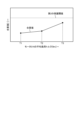
- Fig. 3 indicates the average load torque applied to the motor 314, and the vertical axis of Fig. 3 indicates the effective value Vdc-rpl-rms of the capacitor voltage ripple. That is, Fig. 3 shows the relationship between the average load torque applied to the motor 314 and the effective value Vdc -rpl-rms of the capacitor voltage ripple.
- the capacitor voltage ripple is the ripple component of the capacitor voltage Vdc .
- the solid line represents the magnitude of the effective value Vdc -rpl-rms of the capacitor voltage ripple when the load proportional compensation limit is not implemented, and the dashed line represents the magnitude of the effective value Vdc -rpl-rms of the capacitor voltage ripple when the load proportional compensation limit is implemented.
- the load proportional correction limit when the average load torque decreases from T2 to T1, it transitions along the solid line in Fig. 3, so that the effective value Vdc -rpl-rms of the capacitor voltage ripple exceeds the first protection threshold before the average load torque reaches T1, and the power conversion device 1 performs a protective operation of lowering the drive frequency of the motor 314 or stopping the drive of the motor 314.
- the load proportional correction limit shown by the dashed line in Fig. 3 is implemented.
- the distribution ratio K margin is set so that the average load torque of the motor 314 and the effective value Vdc -rpl-rms of the capacitor voltage ripple are in a directly proportional relationship, that is, the decrease in the average load torque and the decrease in the effective value Vdc-rpl-rms of the capacitor voltage ripple are in a proportional relationship. If the average load torque of the motor 314 becomes smaller, the distribution ratio K margin also becomes smaller. Reducing the distribution ratio K margin means limiting the torque current for load pulsation compensation control.
- the magnitude relationship between the q-axis current margin Iqmargin , the current limit value IqlimAVS for load pulsation compensation control, and the q-axis current command Iqavs for load pulsation compensation control is Iqmargin ⁇ IqlimAVS ⁇ Iqavs .
- the q-axis current command Iqavs for load pulsation compensation control is a torque current command for load pulsation compensation control.
- the power supply pulsation compensation control unit 413 performs power supply pulsation compensation control within the range of a limit value Iqlimd2v for power supply pulsation compensation control, and generates a q-axis current command Iqd2v for power supply pulsation compensation control.
- the q-axis current command Iqd2v for power supply pulsation compensation control is a q-axis current command value calculated by, for example, PI control of a specific frequency component extraction value Vdc -rpl-nfs of a capacitor voltage ripple, which will be described later, so that this specific frequency component extraction value Vdc-rpl- nfs approaches zero.
- An adder 414 adds the q-axis current command Iqsp for constant current load control, which is the addition result of the adder 411, the q-axis current command Iqavs for load pulsation compensation control, and the q-axis current command Iqd2v for power supply pulsation compensation control.
- the q-axis current command generating unit 415 outputs the addition result of the adder 414 to the current control unit 404 as a q-axis current command iq * .
- Fig. 4 shows a detailed configuration example of the first protection threshold generator 416.
- the first protection threshold generator 416 includes an effective value calculator (denoted as "rms" in Fig. 4) 418 and a table 419.
- the effective value calculator 418 inputs the power supply voltage Vs , calculates and outputs the power supply voltage effective value Vs -rms .
- the table 419 inputs the power supply voltage effective value Vs -rms , and outputs a first protection threshold corresponding to the input value of the power supply voltage effective value Vs -rms .
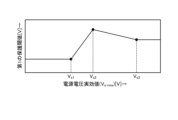
- FIG. 5 shows the relationship between the power supply voltage effective value Vs -rms and the first protection threshold.
- the table data of the table 419 holds data of the relationship shown in FIG. 5. With this table data, the table 419 can set the first protection threshold that can appropriately protect the capacitor 210 against the power supply voltage effective value Vs -rms .
- the table data may hold only protection thresholds for the three power supply voltage effective values Vs -rms Vs1 , Vs2 , and Vs3 shown by black dots in FIG. 5, and protection thresholds for the other three points may be calculated by linear interpolation. In this way, the number of data held in the table data can be reduced. Note that the content described here is an example, and the number of table data held may be other than three, and the interpolation process may be other than linear interpolation.
- the capacitor voltage processing unit 417 outputs a specific frequency component extraction value Vdc -rpl-nfs of the capacitor voltage ripple and a stall request (0: no, 1: yes) based on the capacitor voltage Vdc detected by the first voltage detection unit 500 and the first protection threshold which is the output of the first protection threshold generation unit 416.
- the specific frequency component extraction value Vdc -rpl-nfs of the capacitor voltage ripple is an extraction value when a specific frequency component of the power supply voltage Vs is extracted from the ripple value of the capacitor voltage Vdc .
- the specific frequency component is a frequency component twice the frequency of the power supply voltage Vs when the commercial power supply 110 is a single-phase power supply, and is a frequency component six times the frequency of the power supply voltage Vs when the commercial power supply 110 is a three-phase power supply.
- FIG. 6 shows a detailed configuration example of the capacitor voltage processing unit 417.
- the capacitor voltage processing unit 417 includes an LPF (Low Pass Filter) 420, a subtraction unit 421, a BPF (Band Pass Filter) 422, an effective value calculation unit (denoted as "rms" in Figure 6) 423, and a comparison unit 424.
- LPF Low Pass Filter
- BPF Band Pass Filter
- the LPF 420 extracts a DC component Vdc-lpf of the capacitor voltage Vdc by performing low-pass filtering on the capacitor voltage Vdc .
- the subtraction unit 421 subtracts the DC component Vdc-lpf from the capacitor voltage Vdc , and outputs the subtraction result as a ripple voltage Vdc -rpl of the capacitor voltage Vdc .
- the "ripple voltage” here is synonymous with the above-mentioned "capacitor voltage ripple”
- the ripple voltage Vdc -rpl means the ripple value of the capacitor voltage Vdc .
- the BPF 422 performs band-pass filtering on the ripple voltage Vdc -rpl , and outputs a specific frequency component extracted value Vdc-rpl-nfs in which a specific frequency component is extracted.
- the effective value calculation unit 423 inputs the ripple voltage V dc-rpl, which is the output voltage from the subtraction unit 421, and calculates and outputs the effective value V dc-rpl-rms .
- the comparison unit 424 compares the first protection threshold, which is the output of the first protection threshold generation unit 416, with the effective value V dc-rpl-rms of the capacitor voltage ripple. If the first protection threshold ⁇ V dc-rpl-rms , the comparison unit 424 outputs “0 (no stall request)”. “0 (no stall request)” is an output value indicating that control to reduce the speed command ⁇ * does not need to be performed.
- the effective value Vdc -rpl-rms of the ripple voltage Vdc -rpl is exemplified as the physical quantity to be compared with the first protection threshold, but this is not limiting.
- the object to be compared with the first protection threshold may be any detected value or calculated value that represents a physical quantity having similar characteristics to the capacitor current I3.
- Other examples of the calculated value that represents a physical quantity having similar characteristics to the capacitor current I3 will be described in the second embodiment.
- FIG. 7 is a block diagram showing an example of a hardware configuration for realizing the functions of the control unit 400 according to the first embodiment.
- a configuration including a processor 450 that performs calculations and a memory 452 that stores programs read by the processor 450 can be used, as shown in FIG. 7.
- Processor 450 is an example of a computing means.
- Processor 450 may be a computing means called a microprocessor, a microcomputer, a CPU (Central Processing Unit), or a DSP (Digital Signal Processor).
- Examples of memory 452 include non-volatile or volatile semiconductor memory such as RAM (Random Access Memory), ROM (Read Only Memory), flash memory, EPROM (Erasable Programmable ROM), and EEPROM (registered trademark) (Electrically EPROM), magnetic disks, flexible disks, optical disks, compact disks, mini disks, and DVDs (Digital Versatile Discs).
- the memory 452 holds a program that executes the functions of the control unit 400.
- the processor 450 receives and transmits the necessary information and stores it in the memory 452, and the processor 450 executes the program held in the memory 452 and refers to the data and tables stored in the memory 452, thereby executing the above-mentioned processing.
- the results of calculations by the processor 450 can be stored in the memory 452.
- the control unit detects or calculates a physical quantity that has the same characteristics as the capacitor current, and when this physical quantity exceeds a first protection threshold, controls to lower the motor drive frequency or stop the drive of the motor.
- a physical quantity is the ripple value of the capacitor voltage.
- the torque current command for the load pulsation compensation control may be limited to a range in which the ripple value of the capacitor voltage is proportional to the magnitude of the motor load. If the torque current command for the load pulsation compensation control is limited from this perspective, it becomes possible to set the above-mentioned first protection threshold taking into consideration only the maximum condition of the motor load. This provides the effect of making it possible to simply and easily set the first protection threshold, as well as eliminating the need to set the first protection threshold according to the motor drive frequency and load.
- the first protection threshold is set according to the magnitude of the power supply voltage of the commercial power supply, so that the capacitor can be appropriately protected even if the power supply voltage fluctuates.
- FIG. 8 is a diagram showing a configuration example of a power conversion device 1a according to the second embodiment.
- the control unit 400 is replaced with a control unit 400a.
- the motor drive device 2 is changed to a motor drive device 2a.
- FIG. 9 is a block diagram showing an example of the configuration of a control unit 400a provided in a power conversion device 1a according to embodiment 2.
- the capacitor voltage processing unit 417 is replaced with a capacitor voltage processing unit 417a, and the first protection threshold generating unit 416 is deleted.
- the other configuration is the same as or equivalent to the control unit 400 shown in FIG. 2, and the same or equivalent components are denoted by the same reference numerals, and duplicated explanations will be omitted.
- FIG. 10 is a block diagram showing an example of the configuration of the capacitor voltage processing unit 417a provided in the control unit 400a according to the second embodiment. Also, FIG. 11 is a diagram for explaining the operation of the main parts of the capacitor voltage processing unit 417a according to the second embodiment.
- the capacitor voltage processing unit 417a includes an LPF 420, a subtraction unit 421, BPFs 425 and 427, a first multiplication unit (in FIG. 10, indicated as "nfs x coefficient") 426, a second multiplication unit (in FIG. 10, indicated as "nfm x coefficient") 428, an addition unit 429, and a comparison unit 430.
- the LPF 420 performs low-pass filtering on the capacitor voltage Vdc to extract the DC component Vdc -lpf of the capacitor voltage Vdc.
- the subtraction unit 421 subtracts the DC component Vdc-lpf from the capacitor voltage Vdc and outputs the subtraction result as the ripple voltage Vdc -rpl of the capacitor voltage Vdc.
- the BPF 425 performs band-pass filtering on the ripple voltage Vdc -rpl to output a specific frequency component extraction value Vdc -rpl-nfs that extracts a specific frequency component, and also outputs a specific frequency component amplitude value Vdc-rpl-nfs-amp that is the amplitude value of the specific frequency component extraction value Vdc-rpl-nfs-amp .
- the specific frequency component extraction value Vdc -rpl-nfs extracted and output by the BPF 425 is the same as the value extracted by the capacitor voltage processing unit 417 in the first embodiment.
- the BPF 427 performs band-pass filtering on the ripple voltage Vdc -rpl to extract the main component frequency of the load pulsation of the motor 314, and outputs the load pulsation frequency component amplitude value Vdc -rpl-nfm-amp, which is the amplitude value of the extracted main component frequency.
- the main component frequency of the load pulsation of the motor 314 is a single component of the mechanical angle drive frequency when the compressor 315 is a single rotary compressor, and is a double component of the mechanical angle drive frequency when the compressor 315 is a twin rotary compressor.
- the first multiplier 426 outputs a multiplied value obtained by multiplying the specific frequency component amplitude value V dc-rpl-nfs-amp output from the BPF 425 by the frequency nfs of the extracted specific frequency component and a predetermined coefficient.
- the second multiplier 428 outputs a multiplied value obtained by multiplying the load ripple frequency component amplitude value V dc-rpl-nfm-amp output from the BPF 427 by the extracted main component frequency nfm and a predetermined coefficient.
- the adder 429 outputs a sum of the multiplied value output from the first multiplier 426 and the multiplied value output from the second multiplier 428.
- the coefficient used in the first multiplication unit 426 and the second multiplication unit 428 is the same fixed value.
- the capacitance value of the capacitor 210 is represented by "C”
- this coefficient is "C x 2 ⁇ ”
- the values output from the first multiplication unit 426 and the second multiplication unit 428 correspond to the amplitude value of the component of frequency nfs and the amplitude value of the component of main component frequency nfm, respectively, contained in the capacitor current I3.
- the capacitor voltage Vc and the capacitor current Ic flowing through the capacitor have the relationship expressed by the following formula (1).
- the ripple voltage V dc-rpl is expressed by the following formula (2).
- ⁇ 1 , ⁇ 2 , and ⁇ 3 are angular frequencies of dominant frequency components in the ripple voltage Vdc-rpl .
- ⁇ 1 , ⁇ 2 , and ⁇ 3 are phases corresponding to the angular frequencies ⁇ 1 , ⁇ 2 , and ⁇ 3 , respectively.
- V1 , V2 , and V3 are amplitudes corresponding to the angular frequencies ⁇ 1 , ⁇ 2 , and ⁇ 3 , respectively.
- the ripple current I c-rpl flowing in the capacitor 210 due to the ripple voltage V dc-rpl can be expressed as in the following equation (3).
- the adder 429 performs the above calculation and outputs the sum.
- the sum output from the adder 429 is as shown in FIG. 11 for the average load torque of the motor 314.
- FIG. 11 shows the relationship between the average load torque applied to the motor 314 and the sum. The graph is presented in the same way as in FIG. 3.
- the sum output from the adder 429 can be expressed as a proportional relationship between the average load torques T1 and T2, and between the average load torque T2 and the MAX load T3.
- the second protection threshold is a value determined for the sum, and is set by measuring or simulating in advance a value that can ensure the life of the capacitor 210 under the condition of the MAX load T3.
- the coefficients used in the first multiplier 426 and the second multiplier 428 may be standardized as "1", and the second protection threshold may be set corresponding to the standardized coefficient.
- the comparison unit 430 compares the sum, which is the output of the addition unit 429, with the second protection threshold. If the second protection threshold is equal to or greater than the sum, the comparison unit 430 outputs "0 (no stall request)". As in the first embodiment, "0 (no stall request)" is an output value indicating that control to reduce the speed command ⁇ * does not need to be performed. Also, if the second protection threshold is less than the sum, the comparison unit 430 outputs "1 (stall request present)". As in the first embodiment, "1 (stall request present)" is an output value indicating that control to reduce the speed command ⁇ * should be performed.
- the control unit detects or calculates a physical quantity having the same characteristics as the capacitor current, and when this physical quantity exceeds the second protection threshold, controls to lower the motor drive frequency or stop the drive of the motor.
- a physical quantity is the sum of a dominant frequency component extracted from the ripple value of the capacitor voltage and multiplying the amplitude of the extracted frequency component by this frequency component and a predetermined coefficient.
- the sum calculated as described above is used to perform threshold determination, so it is possible to protect the capacitor without implementing the load proportional compensation limit as in the first embodiment.
- This has the effect of eliminating the constraint on the torque current command for load pulsation compensation control, which is to implement the load proportional compensation limit.
- Fig. 12 is a diagram showing a configuration example of a refrigeration cycle-applied device 900 according to embodiment 3.
- the refrigeration cycle-applied device 900 according to embodiment 3 includes the power conversion device 1 described in embodiment 1.
- the refrigeration cycle-applied device 900 according to embodiment 3 can be applied to products including a refrigeration cycle, such as air conditioners, refrigerators, freezers, and heat pump water heaters.
- a refrigeration cycle such as air conditioners, refrigerators, freezers, and heat pump water heaters.
- components having the same functions as those in embodiment 1 are denoted by the same reference numerals as those in embodiment 1.
- the refrigeration cycle application device 900 includes a compressor 315 incorporating the motor 314 in the first embodiment, a four-way valve 902, an indoor heat exchanger 906, an expansion valve 908, and an outdoor heat exchanger 910, which are attached via a refrigerant pipe 912.
- a compression mechanism 904 that compresses the refrigerant, and a motor 314 that operates the compression mechanism 904.
- the refrigeration cycle device 900 can perform heating or cooling operation by switching the four-way valve 902.
- the compression mechanism 904 is driven by a variable speed controlled motor 314.
- the refrigerant is pressurized by the compression mechanism 904 and sent out, passes through the four-way valve 902, the outdoor heat exchanger 910, the expansion valve 908, the indoor heat exchanger 906, and the four-way valve 902, and returns to the compression mechanism 904.
- the indoor heat exchanger 906 acts as a condenser to release heat, and the outdoor heat exchanger 910 acts as an evaporator to absorb heat.
- the outdoor heat exchanger 910 acts as a condenser to release heat, and the indoor heat exchanger 906 acts as an evaporator to absorb heat.
- the expansion valve 908 reduces the pressure of the refrigerant to expand it.
- the refrigeration cycle application device 900 according to the third embodiment has been described as including the power conversion device 1 described in the first embodiment, but is not limited to this. It may also be configured to include the power conversion device 1a shown in FIG. 8. Also, a power conversion device other than the power conversion devices 1 and 1a may be used as long as the control methods of the first and second embodiments can be applied.
- the refrigeration cycle application device is configured with the power conversion device according to the first or second embodiment, so that it is possible to provide a product that can be appropriately controlled in temperature, can suppress vibrations generated by the compressor, and can ensure a long product life while keeping the price down.
- a physical quantity having the same characteristics as the capacitor current I3 is calculated indirectly from the ripple voltage Vdc -rpl of the capacitor voltage Vdc, but the capacitor current I3 may be directly detected to suppress deterioration of the capacitor 210.
Landscapes
- Engineering & Computer Science (AREA)
- Power Engineering (AREA)
- Control Of Ac Motors In General (AREA)
- Inverter Devices (AREA)
Priority Applications (2)
| Application Number | Priority Date | Filing Date | Title |
|---|---|---|---|
| JP2024567099A JP7834200B2 (ja) | 2022-12-27 | 2022-12-27 | 電力変換装置、モータ駆動装置及び冷凍サイクル適用機器 |
| PCT/JP2022/048393 WO2024142324A1 (ja) | 2022-12-27 | 2022-12-27 | 電力変換装置、モータ駆動装置及び冷凍サイクル適用機器 |
Applications Claiming Priority (1)
| Application Number | Priority Date | Filing Date | Title |
|---|---|---|---|
| PCT/JP2022/048393 WO2024142324A1 (ja) | 2022-12-27 | 2022-12-27 | 電力変換装置、モータ駆動装置及び冷凍サイクル適用機器 |
Publications (1)
| Publication Number | Publication Date |
|---|---|
| WO2024142324A1 true WO2024142324A1 (ja) | 2024-07-04 |
Family
ID=91716885
Family Applications (1)
| Application Number | Title | Priority Date | Filing Date |
|---|---|---|---|
| PCT/JP2022/048393 Ceased WO2024142324A1 (ja) | 2022-12-27 | 2022-12-27 | 電力変換装置、モータ駆動装置及び冷凍サイクル適用機器 |
Country Status (2)
| Country | Link |
|---|---|
| JP (1) | JP7834200B2 (https=) |
| WO (1) | WO2024142324A1 (https=) |
Citations (3)
| Publication number | Priority date | Publication date | Assignee | Title |
|---|---|---|---|---|
| JP2009038891A (ja) * | 2007-08-01 | 2009-02-19 | Nissan Motor Co Ltd | 電力変換装置及び電力変換装置の制御方法 |
| JP2019176680A (ja) * | 2018-03-29 | 2019-10-10 | ダイキン工業株式会社 | 電力変換装置 |
| JP2020150702A (ja) * | 2019-03-14 | 2020-09-17 | ダイキン工業株式会社 | 直接形の電力変換装置 |
Family Cites Families (4)
| Publication number | Priority date | Publication date | Assignee | Title |
|---|---|---|---|---|
| JP4757680B2 (ja) * | 2006-03-24 | 2011-08-24 | 三菱電機株式会社 | 空気調和装置 |
| JP6729250B2 (ja) * | 2016-09-30 | 2020-07-22 | ダイキン工業株式会社 | 電力変換器の制御装置 |
| JP6343037B1 (ja) * | 2017-01-11 | 2018-06-13 | 日立ジョンソンコントロールズ空調株式会社 | モータ駆動装置および冷凍機器 |
| JP7330401B2 (ja) * | 2021-01-06 | 2023-08-21 | 三菱電機株式会社 | 電力変換装置、モータ駆動装置および冷凍サイクル適用機器 |
-
2022
- 2022-12-27 JP JP2024567099A patent/JP7834200B2/ja active Active
- 2022-12-27 WO PCT/JP2022/048393 patent/WO2024142324A1/ja not_active Ceased
Patent Citations (3)
| Publication number | Priority date | Publication date | Assignee | Title |
|---|---|---|---|---|
| JP2009038891A (ja) * | 2007-08-01 | 2009-02-19 | Nissan Motor Co Ltd | 電力変換装置及び電力変換装置の制御方法 |
| JP2019176680A (ja) * | 2018-03-29 | 2019-10-10 | ダイキン工業株式会社 | 電力変換装置 |
| JP2020150702A (ja) * | 2019-03-14 | 2020-09-17 | ダイキン工業株式会社 | 直接形の電力変換装置 |
Also Published As
| Publication number | Publication date |
|---|---|
| JP7834200B2 (ja) | 2026-03-23 |
| JPWO2024142324A1 (https=) | 2024-07-04 |
Similar Documents
| Publication | Publication Date | Title |
|---|---|---|
| JP7466794B2 (ja) | 電力変換装置、モータ駆動装置および冷凍サイクル適用機器 | |
| WO2023084600A1 (ja) | 電力変換装置、モータ駆動装置及び冷凍サイクル適用機器 | |
| JP7566175B2 (ja) | 電力変換装置、電動機駆動装置及び冷凍サイクル適用機器 | |
| WO2023073870A1 (ja) | 電力変換装置、モータ駆動装置および冷凍サイクル適用機器 | |
| JP7580632B2 (ja) | 電力変換装置、モータ駆動装置および冷凍サイクル適用機器 | |
| WO2023105570A1 (ja) | 電力変換装置、モータ駆動装置及び冷凍サイクル適用機器 | |
| US20240014759A1 (en) | Control device, power conversion apparatus, motor drive unit, and applied refrigeration cycle apparatus | |
| JP7592188B2 (ja) | 電力変換装置、モータ駆動装置および冷凍サイクル適用機器 | |
| JP7595807B2 (ja) | モータ駆動装置及び冷凍サイクル装置 | |
| JP7330401B2 (ja) | 電力変換装置、モータ駆動装置および冷凍サイクル適用機器 | |
| WO2024142324A1 (ja) | 電力変換装置、モータ駆動装置及び冷凍サイクル適用機器 | |
| JP7566174B2 (ja) | 電力変換装置、電動機駆動装置及び冷凍サイクル適用機器 | |
| WO2023100321A1 (ja) | 電力変換装置、モータ駆動装置及び冷凍サイクル適用機器 | |
| JP7499887B2 (ja) | 電力変換装置、モータ駆動装置および冷凍サイクル適用機器 | |
| WO2025069183A1 (ja) | 電力変換装置、電動機駆動装置及び冷凍サイクル適用機器 | |
| WO2023157045A1 (ja) | 電力変換装置および空気調和機 | |
| JP7325671B2 (ja) | 電力変換装置、モータ駆動装置および冷凍サイクル適用機器 | |
| JP7592187B2 (ja) | 電力変換装置、モータ駆動装置および冷凍サイクル適用機器 | |
| WO2023067774A1 (ja) | 電力変換装置、モータ駆動装置および冷凍サイクル適用機器 | |
| JP7819347B2 (ja) | 電力変換装置、モータ駆動装置および冷凍サイクル適用機器 | |
| JP7515740B2 (ja) | 電力変換装置、電動機駆動装置及び冷凍サイクル適用機器 | |
| JP7799851B2 (ja) | 電力変換装置、モータ駆動装置および冷凍サイクル適用機器 | |
| WO2023105676A1 (ja) | 電力変換装置、モータ駆動装置及び冷凍サイクル適用機器 | |
| US20250219553A1 (en) | Power converting apparatus, motor drive apparatus, and refrigeration-cycle application device | |
| WO2024184960A1 (ja) | 電力変換装置および空気調和機 |
Legal Events
| Date | Code | Title | Description |
|---|---|---|---|
| 121 | Ep: the epo has been informed by wipo that ep was designated in this application |
Ref document number: 22970113 Country of ref document: EP Kind code of ref document: A1 |
|
| WWE | Wipo information: entry into national phase |
Ref document number: 2024567099 Country of ref document: JP |
|
| NENP | Non-entry into the national phase |
Ref country code: DE |
|
| 122 | Ep: pct application non-entry in european phase |
Ref document number: 22970113 Country of ref document: EP Kind code of ref document: A1 |