WO2024135504A1 - 電流センサ - Google Patents
電流センサ Download PDFInfo
- Publication number
- WO2024135504A1 WO2024135504A1 PCT/JP2023/044734 JP2023044734W WO2024135504A1 WO 2024135504 A1 WO2024135504 A1 WO 2024135504A1 JP 2023044734 W JP2023044734 W JP 2023044734W WO 2024135504 A1 WO2024135504 A1 WO 2024135504A1
- Authority
- WO
- WIPO (PCT)
- Prior art keywords
- core
- bus bar
- protrusion
- detection element
- magnetic field
- Prior art date
- Legal status (The legal status is an assumption and is not a legal conclusion. Google has not performed a legal analysis and makes no representation as to the accuracy of the status listed.)
- Ceased
Links
Images










Classifications
-
- G—PHYSICS
- G01—MEASURING; TESTING
- G01R—MEASURING ELECTRIC VARIABLES; MEASURING MAGNETIC VARIABLES
- G01R15/00—Details of measuring arrangements of the types provided for in groups G01R17/00 - G01R29/00, G01R33/00 - G01R33/26 or G01R35/00
- G01R15/14—Adaptations providing voltage or current isolation, e.g. for high-voltage or high-current networks
- G01R15/20—Adaptations providing voltage or current isolation, e.g. for high-voltage or high-current networks using galvano-magnetic devices, e.g. Hall-effect devices, i.e. measuring a magnetic field via the interaction between a current and a magnetic field, e.g. magneto resistive or Hall effect devices
Definitions
- This disclosure relates to a current sensor.
- a current sensor As described in Patent Document 1, a current sensor is known that includes a bus bar through which a current flows, a core into which the bus bar is inserted and through which a magnetic field generated by the current flowing through the bus bar passes, and a sensor chip that serves as a detection element and is disposed in the gap of the core. In this current sensor, the strength of the magnetic field passing through the gap is detected by the sensor chip, thereby detecting the current flowing through the bus bar.
- two bus bars may be inserted into the core for current detection.
- the strength of the magnetic field generated by the current flowing through the two bus bars, which have different current directions, is detected by the sensor chip, and the current flowing through the bus bars is detected.
- the gap there are places where the directions of the magnetic fields generated by the current flowing through the two bus bars are opposite to each other, and therefore there are places where the two magnetic fields cancel each other out.
- the direction of the magnetic field generated by the current flowing through the two bus bars is from the gap toward the bottom of the core located on the opposite side to the gap, and therefore there are places where the two magnetic fields are difficult to cancel each other out.
- An object of the present disclosure is to provide a current sensor that suppresses deterioration in current detection accuracy.
- a current sensor comprising: a first bus bar formed in a plate shape and through which a current flows in one of the longitudinal directions; a second bus bar formed in a plate shape aligned with the first bus bar at a distance from the first bus bar in the width direction of the first bus bar and through which a current flows in a direction opposite to the direction of the current flowing in the first bus bar; a core hole into which the first bus bar and the second bus bar are inserted; a first end face facing the width direction, a second end face facing the first end face in the width direction, and a gap forming portion formed by the first end face and the second end face and including a gap connecting the core hole to the outside; a core lateral portion connected to the gap forming portion and extending in the thickness direction of the first bus bar; and a core bottom portion connected to the core lateral portion and extending in the width direction, forming a core hole together with the gap forming portion and the core lateral portion; and a core disposed in
- a detection element that detects the strength of a combined magnetic field of a magnetic field generated by a current flowing through the second bus bar in a direction from the first end face to the second end face and a magnetic field generated by a current flowing through the second bus bar in a direction from the second end face to the first end face, and outputs a signal according to the strength of the detected magnetic field.
- the first bus bar has a first opposing surface that faces the second bus bar in the width direction
- the second bus bar has a second opposing surface that faces the first bus bar in the width direction
- the first end surface and the second end surface are located between the first opposing surface and the second opposing surface in the width direction
- the gap forming portion includes a core inner surface and a core protrusion
- the core inner surface is a surface of the gap forming portion that faces inward in the thickness direction
- the core protrusion is a current sensor that protrudes in the thickness direction from a range between a surface of the core inner surface that passes through the first opposing surface and the gap forming portion and is perpendicular to the width direction, and a surface that passes through the second opposing surface and the gap forming portion and is perpendicular to the width direction.
- the magnetic field lines of the magnetic field generated by the first bus bar and the second bus bar pass through the core protrusion. Therefore, the area around the core protrusion becomes a location where the magnetic fields generated by the currents flowing through the first bus bar and the second bus bar are less likely to cancel each other out. Also, since the core protrusion protrudes in the thickness direction from the inner surface of the core, the detection element is more likely to move away from the location where the magnetic fields generated by the currents flowing through the first bus bar and the second bus bar are less likely to cancel each other out, compared to when the core protrusion is not formed. Therefore, the change in the signal value of the detection element caused by the misalignment of the detection element is smaller, compared to when the core protrusion is not formed. Therefore, the detection accuracy of the magnetic field strength by the detection element is prevented from decreasing, and the decrease in current detection accuracy is prevented.
- FIG. 2 is a configuration diagram of an on-board charger in which the current sensor of the first embodiment is used.
- FIG. Cross-sectional view taken along line III-III in Figure 2.
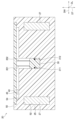
- FIG. 4 is a cross-sectional view of a current sensor of a comparative example.
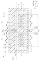
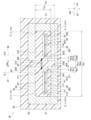
- FIG. 2 is a cross-sectional view of the current sensor according to the first embodiment.
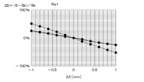
- 11 is a graph showing the relationship between the amount of deviation of a detection element from a reference position and the rate of change in signal value due to deviation from the reference position relative to the signal value of the detection element at the reference position.
- 11 is a graph showing the relationship between the amount of deviation of a detection element from a reference position and the rate of change in signal value due to deviation from the reference position relative to the signal value of the detection element at the reference position.
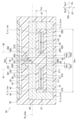
- FIG. 11 is a cross-sectional view of a current sensor according to a second embodiment.
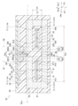
- FIG. 13 is a cross-sectional view of a current sensor according to a third embodiment.
- FIG. 13 is a cross-sectional view of a current sensor according to a fourth embodiment.
- FIG. 13 is a cross-sectional view of a current sensor according to a fifth embodiment.
- FIG. 13 is a cross-sectional view of a current sensor according to a sixth embodiment.
- FIG. 13 is a cross-sectional view of a current sensor according to a seventh embodiment.
- FIG. 13 is a cross-sectional view of a current sensor according to an eighth embodiment.
- FIG. 11 is a graph showing the relationship between the amount of deviation of a detection element from a reference position and the rate of change in signal value due to deviation from the reference position relative to the signal value of the detection element at the reference position.
- FIG. 13 is a cross-sectional view of a current sensor according to a ninth embodiment.
- FIG. 23 is a cross-sectional view of a current sensor according to a tenth embodiment.
- FIG. 23 is a cross-sectional view of a current sensor according to an eleventh embodiment.
- FIG. 23 is a perspective view of a current sensor according to a twelfth embodiment.
- FIG. 23 is a cross-sectional view of a current sensor in a modified example of the twelfth embodiment.
- FIG. 23 is a cross-sectional view of a current sensor in a modified example of the twelfth embodiment.
- FIG. 23 is a cross-sectional view of a current sensor in a modified example of the twelfth embodiment.
- FIG. 23 is a cross-sectional view of a current sensor in a modified example of the twelfth embodiment.
- FIG. 23 is a cross-sectional view of a current sensor in a modified example of the twelfth embodiment.
- the current sensor of this embodiment is used, for example, in an on-board charger 10 as shown in Fig. 1. First, the on-board charger 10 will be described.
- the on-board charger 10 includes a battery 12, a charger 14, and a current sensor 20.
- the battery 12 is a rechargeable secondary battery, such as a nickel-metal hydride battery or a lithium-ion battery.
- the battery 12 corresponds to a load.
- the charger 14 is equipped with an AC-DC converter and the like, and converts AC power from a grid power source into DC power. Furthermore, the charger 14 supplies this converted DC power to the battery 12, thereby charging the battery 12.
- the charger 14 corresponds to a power source.
- the current sensor 20 detects the current flowing between the battery 12 and the charger 14. Based on the detected current, the current sensor 20 also determines whether or not there is an electrical leakage abnormality between the battery 12 and the charger 14. Details of the current sensor 20 will be described later.
- the on-board charger 10 is configured as described above. Next, we will explain the current sensor 20.
- the current sensor 20 includes a first bus bar 21, a second bus bar 22, a core 25, a detection unit 30, lead wires 35, a substrate 40, a determination unit 45, and a case 50.
- the first bus bar 21 is formed in a plate shape.
- the first bus bar 21 is made of copper or the like and is therefore conductive. If necessary, the surface of the first bus bar 21 is plated to prevent oxidation of the surface.
- One end of the first bus bar 21 is connected to one end of the charger 14. The other end of the first bus bar 21 is connected to one end of the battery 12. As described below, a current flows through the first bus bar 21 in one direction along the longitudinal direction DL of the first bus bar 21.
- the longitudinal direction DL of the first bus bar 21 will be simply referred to as the longitudinal direction DL.
- the width direction DW of the first bus bar 21 will be simply referred to as the width direction DW.
- the thickness direction DT of the first bus bar 21 will be simply referred to as the thickness direction DT.
- the first bus bar 21 includes a first opposing surface 211.
- the first opposing surface 211 faces the second bus bar 22 (described later) in the width direction DW.
- the first opposing surface 211 is a surface that is perpendicular to the width direction DW and corresponds to a surface that intersects with the width direction DW.
- the second bus bar 22 is arranged in the width direction DW with a gap between it and the first bus bar 21.
- the second bus bar 22 is formed in a plate shape, similar to the first bus bar 21.
- the second bus bar 22 is made of copper or the like, and is therefore conductive.
- the surface of the second bus bar 22 is plated to prevent oxidation of the surface, as necessary.
- One end of the second bus bar 22 is connected to the other end of the battery 12.
- the other end of the second bus bar 22 is connected to the other end of the charger 14.
- a series circuit is formed by the battery 12, the charger 14, and the current sensor 20. As described below, a current flows through the second bus bar 22 in a direction opposite to the direction of the current flowing through the first bus bar 21.
- the second bus bar 22 also includes a second opposing surface 222.
- the second opposing surface 222 faces the first opposing surface 211 of the first bus bar 21 in the width direction DW. Furthermore, the second opposing surface 222 is a surface that is perpendicular to the width direction DW and corresponds to a surface that intersects with the width direction DW.
- the core 25 is formed in a C-shape from a soft magnetic material such as permalloy or directional electromagnetic steel plate.
- the core 25 is formed, for example, by bending a plate of soft magnetic material into a C-shape.
- the core 25 further has a gap forming portion 26, a core side portion 27, a core bottom portion 28, and a core hole 29.
- the gap forming portion 26 is formed in a plate shape extending in the width direction DW. Furthermore, the gap forming portion 26 is separated from the first bus bar 21 and the second bus bar 22 in the thickness direction DT. Furthermore, the gap forming portion 26 includes a first end face 261, a second end face 262, a gap 265, a first core inner surface 271, a first core protrusion 281, a second core inner surface 272, and a second core protrusion 282.
- the first end face 261 faces the width direction DW.
- the second end face 262 faces the width direction DW and faces the first end face 261 in the width direction DW. Furthermore, when the first end face 261 is projected in the width direction DW, the second end face 262 overlaps with the projected first end face 261.
- the gap 265 is a space defined by the first end face 261 and the second end face 262. Furthermore, the gap 265 is connected to the core hole 29 and the outside of the core 25, which will be described later. Furthermore, the first end face 261, the second end face 262, and the gap 265 are located between the first opposing surface 211 and the second opposing surface 222 in the width direction DW.
- the first core inner surface 271 is a surface of the gap forming portion 26 that faces inward in the thickness direction DT and faces the first bus bar 21 in the thickness direction DT. Furthermore, when the first bus bar 21 is projected in the thickness direction DT, the first core inner surface 271 overlaps with the projected first bus bar 21.
- the surface that passes through the first opposing surface 211 and the gap forming portion 26 and is perpendicular to the width direction DW is defined as the first surface S1.
- the surface that passes through the second opposing surface 222 and the gap forming portion 26 and is perpendicular to the width direction DW is defined as the second surface S2.
- the first core protrusion 281 protrudes in the thickness direction DT from the range between the first surface S1 and the second surface S2 of the first core inner surface 271, in this case, the range between the first surface S1 and the first end surface 261. Furthermore, the first core protrusion 281 is formed, for example, in a rectangular prism shape. Note that the first core protrusion 281 is not limited to being formed in a rectangular prism shape, and may be formed, for example, in a polygonal prism shape, a cylindrical shape, an elliptical cylinder shape, a hemisphere shape, a semi-elliptical sphere shape, etc.
- the maximum length of the first core protrusion 281 in the width direction DW is defined as the first protrusion width Wp1.
- the distance from the first opposing surface 211 to the first end surface 261 in the width direction DW is defined as the first distance Wb1.
- the first protrusion width Wp1 is set to be less than or equal to the first distance Wb1, i.e., Wp1 ⁇ Wb1.
- the second core inner surface 272 is a surface of the gap forming portion 26 that faces inward in the thickness direction DT and faces the second bus bar 22 in the thickness direction DT. Furthermore, when the second bus bar 22 is projected in the thickness direction DT, the second core inner surface 272 overlaps with the projected second bus bar 22.
- the second core protrusion 282 protrudes in the thickness direction DT from the range between the first surface S1 and the second surface S2 of the second core inner surface 272, in this case, the range between the second surface S2 and the second end surface 262. Furthermore, the second core protrusion 282 is formed, for example, in a rectangular prism shape. Note that the second core protrusion 282 is not limited to being formed in a rectangular prism shape, and may be formed, for example, in a polygonal prism shape, a cylindrical shape, an elliptical cylinder shape, a hemisphere shape, a semi-elliptical sphere shape, etc.
- the maximum length of the second core protrusion 282 in the width direction DW is defined as the second protrusion width Wp2.
- the distance from the second opposing surface 222 to the second end surface 262 in the width direction DW is defined as the second distance Wb2.
- the second protrusion width Wp2 is set to be less than or equal to the second distance Wb2, i.e., Wp2 ⁇ Wb2.
- the core horizontal portion 27 is connected to the gap forming portion 26.
- the core horizontal portion 27 extends in the thickness direction DT from the boundary between the core horizontal portion 27 and the gap forming portion 26.
- the lateral inner corner C_in_top which is the inner corner at the boundary between the core horizontal portion 27 and the gap forming portion 26, is rounded.
- the core horizontal portion 27 is separated from the first bus bar 21 and the second bus bar 22 in the width direction DW.
- the core bottom 28 is connected to the core side 27. Furthermore, the core bottom 28 extends in the width direction DW, passing through the first surface S1 and the second surface S2. In addition, the bottom inner corner C_in_btm, which is the inner corner at the boundary between the core bottom 28 and the core side 27, is rounded. Furthermore, the magnetic permeability of the core bottom 28 is smaller than that of the core side 27, that is, the magnetic permeability of the core side 27 is larger than that of the core bottom 28. As a result, the linear region of the magnetic flux density of the core side 27 relative to the magnetic field strength is larger than the linear region of the magnetic flux density of the core bottom 28 relative to the magnetic field strength. For this reason, magnetic saturation of the core side 27 is easily suppressed. Note that the magnetic permeability refers to, for example, the maximum magnetic permeability, which is the maximum value of the change in magnetic flux density relative to the magnetic field strength.
- the core bottom 28 also includes a bottom inner surface 280.
- the bottom inner surface 280 faces inward in the thickness direction DT. Furthermore, the bottom inner surface 280 faces the first bus bar 21 and the second bus bar 22 in the thickness direction DT.
- the core hole 29 is a space formed by the gap forming portion 26, the core side portion 27, and the core bottom portion 28. In addition, a portion of the first bus bar 21 and the second bus bar 22 are inserted into the core hole 29.
- the minimum distance from the first end face 261 to the second end face 262 in the width direction DW is the gap distance Gap.
- the maximum distance from the inner surface of the gap forming portion 26 to the inner surface of the core bottom portion 28 in the thickness direction DT is the inner surface distance Tch.
- the maximum distance between the inner surfaces of the core lateral portions 27 that face each other in the width direction DW is the lateral portion distance Wsi.
- the distance between the inner faces, Tch is greater than the gap distance, Gap, i.e., Tch>Gap. Furthermore, the distance between the lateral portions, Wsi, is greater than the distance between the inner faces, Tch, i.e., Wsi>Tch. Therefore, Wsi>Tch>Gap.
- the detection unit 30 is disposed in the gap 265. Therefore, when the first end face 261 is projected in the width direction DW, the detection unit 30 overlaps with the projected first end face 261. Furthermore, when the second end face 262 is projected in the width direction DW, the detection unit 30 overlaps with the projected second end face 262. Furthermore, the detection unit 30 includes a detection element 31 and an IC (not shown), etc. Note that IC is an abbreviation for Integrated Circuit.
- the detection element 31 is a Hall element, a TMR element, a GMR element, an AMR element, or the like.
- the detection element 31 detects the strength of the magnetic field in the width direction DW, which is the strength of the magnetic field obtained by combining the magnetic field in the first direction Dm1 and the magnetic field in the second direction Dm2, as described later.
- the detection element 31 outputs a signal corresponding to the strength of the detected magnetic field to the outside, for example, a voltage corresponding to the strength of the detected magnetic field.
- TMR is an abbreviation for Tunnel Magneto Resistive.
- GMR is an abbreviation for Giant Magneto Resistive.
- AMR is an abbreviation for Anisotropic Magneto Resistive.
- the first direction Dm1 is the direction from the first end face 261 to the second end face 262.
- the second direction Dm2 is the direction from the second end face 262 to the first end face 261.
- the gap center plane So_Gap the plane that passes through the center of the first end face 261 in the thickness direction DT and is perpendicular to the thickness direction DT.
- the detection element 31 is disposed on the gap center plane So_Gap.
- the gap center plane So_Gap may be a plane that passes through the center of the second end face 262 in the thickness direction DT and is perpendicular to the thickness direction DT.
- the lead wires 35 are connected to the detection unit 30.
- the board 40 is a printed circuit board.
- the board 40 is also connected to the lead wires 35 by soldering or the like.
- the determination unit 45 is mainly composed of an IC and a microcomputer, and includes a CPU, ROM, flash memory, RAM, I/O, drive circuit, AD converter, low-pass filter, communication circuit, and a bus line connecting these components.
- the determination unit 45 is disposed on the board 40.
- the determination unit 45 acquires a signal from the detection element 31 via the lead wire 35 and the board 40 by executing a program stored in the ROM of the determination unit 45.
- the determination unit 45 calculates the leakage current M_leak that has occurred between the battery 12 and the charger 14 based on the acquired signal, and determines whether or not there is a leakage current abnormality.
- the determination unit 45 outputs a signal according to this determination result to an external device such as an alarm device (not shown) via a terminal (not shown).
- the case 50 is formed by injection molding using a thermoplastic resin such as polybutylene terephthalate.
- the case 50 is also formed with a collar (not shown). An external shaft or the like is inserted into this collar to connect the case 50 to the outside. This fixes the current sensor 20 to the outside.
- the case 50 has a core accommodating chamber 52, a substrate accommodating chamber 54, a first opening 61 and a second opening 62.
- the core 25 is housed in the core housing chamber 52.
- a resin such as urethane (not shown) is filled into the core housing chamber 52 between the inner surface of the case 50 and the surface of the core 25 by insert molding or the like. This seals the core housing chamber 52, protecting each part such as the core 25.
- the substrate housing chamber 54 houses the detection unit 30, the lead wires 35, the substrate 40, and the determination unit 45. In addition, since the detection unit 30 is disposed in the gap 265, the substrate housing chamber 54 is formed on the gap 265 side of the case 50.
- a portion of the first opening 61 is inserted into the core hole 29 on the first bus bar 21 side. Also, a portion of the first bus bar 21 is inserted into the space of the first opening 61. Furthermore, the first opening 61 includes a first opening surface 610 and a first opening protrusion 612.
- the first opening surface 610 faces the first bus bar 21 in the width direction DW and thickness direction DT.
- the first opening protrusion 612 protrudes from the first opening surface 610 towards the first bus bar 21. This brings the first opening protrusion 612 into contact with the first bus bar 21. This determines the positioning of the case 50 and the first bus bar 21. Furthermore, a space is formed between the first opening surface 610 and the first bus bar 21.
- a portion of the second opening 62 is inserted into the core hole 29 on the second bus bar 22 side. Also, a portion of the second bus bar 22 is inserted into the space of the second opening 62. Furthermore, the second opening 62 includes a second opening surface 620 and a second opening protrusion 622.
- the second opening surface 620 faces the second bus bar 22 in the width direction DW and thickness direction DT.
- the second opening protrusion 622 protrudes from the second opening surface 620 toward the second bus bar 22. This brings the second opening protrusion 622 into contact with the second bus bar 22. This determines the positioning of the case 50 and the second bus bar 22. Furthermore, a space is formed between the second opening surface 620 and the second bus bar 22.
- the current sensor 20 of the first embodiment is configured as described above. Next, we will explain how the current sensor 20 detects current and determines an abnormal leakage current.
- one end of the first bus bar 21 is connected to one end of the charger 14.
- the other end of the first bus bar 21 is connected to one end of the battery 12.
- One end of the second bus bar 22 is connected to the other end of the battery 12.
- the other end of the second bus bar 22 is connected to the other end of the charger 14. Therefore, when the battery 12 is charged by the charger 14, as shown in FIG. 1 and FIG. 3, a first current Ic1 flows from the charger 14 to the battery 12 via the first bus bar 21.
- a second current Ic2 flows from the battery 12 to the charger 14 via the second bus bar 22.
- the first current Ic1 flowing through the first bus bar 21 generates a circumferential magnetic field centered on an axis that passes through the first bus bar 21 and extends in the longitudinal direction DL.
- This generated magnetic field causes magnetic field lines to pass through the first bus bar 21 side of the gap forming portion 26.
- Some of the magnetic field lines that pass through this gap forming portion 26 pass through the first bus bar 21 side of the core bottom 28 via the first core protrusion 281 and the core hole 29.
- some of the magnetic field lines that pass through this gap forming portion 26 pass from the first end face 261 through the gap 265 and the detection element 31 to the second end face 262.
- the second current Ic2 flowing through the second bus bar 22 generates a circumferential magnetic field centered on an axis that passes through the second bus bar 22 and extends in the longitudinal direction DL.
- This generated magnetic field causes magnetic field lines to pass through the second bus bar 22 side of the gap forming portion 26.
- Some of the magnetic field lines that pass through this gap forming portion 26 pass through the second core protrusion 282 and the core hole 29 to the second bus bar 22 side of the core bottom 28.
- Some of the magnetic field lines that pass through this gap forming portion 26 pass from the second end face 262 through the gap 265 and the detection element 31 to the first end face 261.
- the detection element 31 detects the strength of the combined magnetic field of the first direction Dm1 and the second direction Dm2. As a result, the detection element 31 detects the first current Ic1 and the second current Ic2. The detection element 31 also outputs a signal corresponding to the strength of the detected magnetic field to the determination unit 45 via the lead wire 35 and the substrate 40.
- the battery 12, charger 14, and current sensor 20 are connected in series, and therefore the first current Ic1 and the second current Ic2 are the same. Therefore, the strength of the magnetic field in the first direction Dm1 and the strength of the magnetic field in the second direction Dm2 applied to the detection element 31 are the same. Furthermore, the first direction Dm1 is opposite to the second direction Dm2. Therefore, in this case, the strength of the combined magnetic field of the magnetic field in the first direction Dm1 and the magnetic field in the second direction Dm2 applied to the detection element 31 is zero.
- the first current Ic1 and the second current Ic2 are different. Therefore, the strength of the magnetic field in the first direction Dm1 and the strength of the magnetic field in the second direction Dm2 applied to the detection element 31 are different. Therefore, the absolute value of the strength of the magnetic field obtained by combining the magnetic fields in the first direction Dm1 and the second direction Dm2 applied to the detection element 31 becomes greater than zero.
- the determination unit 45 therefore calculates the leakage current amount M_leak based on the signal from the detection element 31, and compares this calculated leakage current amount M_leak with the threshold value M_leak_th. In this way, the determination unit 45 determines whether or not there is a leakage current abnormality between the battery 12 and the charger 14.
- the threshold value M_leak_th is set by experiment, simulation, etc. so that a leakage current abnormality can be determined.
- the determination unit 45 calculates the leakage current amount M_leak from the signal of the detection element 31 and the map.
- the map for calculating the leakage current amount M_leak is set by experiments, simulations, etc. For example, with this map, the calculated leakage current amount M_leak increases as the absolute value increases.
- the determination unit 45 determines that there is no leakage current abnormality, i.e., the current flow between the battery 12 and the charger 14 is normal. Furthermore, when the calculated leakage current amount M_leak is equal to or greater than the threshold value M_leak_th, the determination unit 45 determines that there is a leakage current abnormality between the battery 12 and the charger 14. Furthermore, the determination unit 45 outputs a signal according to this determination result to an external device such as an alarm device (not shown) via a terminal (not shown) or the like.
- the current sensor 20 detects current and determines leakage current anomalies. Next, we will explain how the current sensor 20 prevents a decrease in current detection accuracy.
- the first core protrusion 281 and the second core protrusion 282 are not formed.
- the gap 265 there are places where the directions of the magnetic fields generated by the first current Ic1 and the second current Ic2 are opposite to each other, and therefore there are places where the two magnetic fields cancel each other out.
- the direction of the magnetic field generated by the current flowing through the first bus bar 21 and the second bus bar 22 is from the gap 265 toward the core bottom 28, and therefore there are places where the two magnetic fields do not cancel each other out easily.
- the magnetic field density around the ends of the first end face 261 and the second end face 262 on the core hole 29 side is relatively large.
- the gap forming portion 26 includes a first core inner surface 271, a first core protrusion 281, a second core inner surface 272, and a second core protrusion 282.
- the first core inner surface 271 and the second core inner surface 272 are surfaces facing inward in the thickness direction DT.
- the first core protrusion 281 protrudes in the thickness direction DT from the range of the first core inner surface 271 between the first surface S1 and the second surface S2.
- the second core protrusion 282 protrudes in the thickness direction DT from the range of the second core inner surface 272, the first surface S1, and the second surface S2.
- the magnetic field lines that pass through the second bus bar 22 side of the gap forming portion 26 pass through the second core protrusion 282.
- the magnetic field lines that pass through the second core protrusion 282 pass through the core hole 29 and the second bus bar 22 side of the core bottom 28. For this reason, the area around the second core protrusion 282 is where the magnetic fields generated by the first current Ic1 and the second current Ic2 are unlikely to cancel each other out.
- the first core protrusion 281 protrudes in the thickness direction DT from the first core inner surface 271
- the second core protrusion 282 protrudes in the thickness direction DT from the second core inner surface 272. Therefore, the detection element 31 is more likely to move away from a location where the magnetic fields generated by the first current Ic1 and the second current Ic2 are less likely to cancel each other out, compared to a case in which the first core protrusion 281 and the second core protrusion 282 are not formed.
- the change in the signal value of the detection element 31 caused by the position of the detection element 31 in the width direction DW being shifted from the reference position is smaller than when the first core protrusion 281 and the second core protrusion 282 are not formed. This suppresses the deterioration of the detection accuracy of the magnetic field strength by the detection element 31, and suppresses the deterioration of the current detection accuracy.
- ⁇ X is the amount of deviation of the detection element 31 from the reference position in the width direction DW.
- the amount of deviation in the first direction Dm1 is the amount of deviation in the positive direction of ⁇ X.
- the reference position of the detection element 31 is, for example, the center of the gap 265.
- S is the signal value of the detection element 31.
- Sb is the signal value of the detection element 31 at the reference position.
- ⁇ S is the ratio of the change in the signal value caused by the deviation from the reference position to the signal value of the detection element 31 at the reference position, and is expressed as (S-Sb)/Sb.
- REF and a dashed line show ⁇ S versus ⁇ X when the first core projection 281 and the second core projection 282 are not formed.
- a solid line shows ⁇ S versus ⁇ X when the first core projection 281 and the second core projection 282 are formed.
- the current sensor 20 also provides the following advantages:
- the first core protrusion 281 is separated from the core bottom 28 in the thickness direction DT.
- the second core protrusion 282 is separated from the core bottom 28 in the thickness direction DT.
- the magnetic resistance between the first core protrusion 281 and the core bottom 28 is larger than when the first core protrusion 281 and the core bottom 28 are in contact. Therefore, the magnetic field lines that pass through the first bus bar 21 side of the gap forming portion 26 not only pass through the first core protrusion 281, but also easily pass from the first end face 261 to the second end face 262 via the gap 265 and the detection element 31. Also, compared to when the second core protrusion 282 and the core bottom 28 are in contact, the magnetic resistance between the second core protrusion 282 and the core bottom 28 is larger.
- the magnetic field lines that pass through the second bus bar 22 side of the gap forming portion 26 not only pass through the second core protrusion 282, but also easily pass from the second end face 262 to the first end face 261 via the gap 265 and the detection element 31. Therefore, the number of magnetic field lines that pass through the detection element 31 increases, and the sensitivity of the detection element 31 increases. This increases the SNR. This prevents a decrease in the accuracy of the detection of the magnetic field strength by the detection element 31, and therefore prevents a decrease in the accuracy of the current detection. Note that SNR is an abbreviation for Signal Noise Ratio.
- the first protrusion width Wp1 is equal to or less than the first distance Wb1, i.e., Wp1 ⁇ Wb1.
- the second protrusion width Wp2 is equal to or less than the second distance Wb2, i.e., Wp2 ⁇ Wb2.
- the magnetic resistance of the first core protrusion 281 is larger than when Wp1>Wb1. Therefore, the magnetic field lines that pass through the first bus bar 21 side of the gap forming portion 26 not only pass through the first core protrusion 281, but also easily pass from the first end face 261 to the second end face 262 via the gap 265 and the detection element 31.
- the magnetic resistance of the second core protrusion 282 is larger than when Wp2>Wb2. Therefore, the magnetic field lines that pass through the second bus bar 22 side of the gap forming portion 26 not only pass through the second core protrusion 282, but also easily pass from the second end face 262 to the first end face 261 via the gap 265 and the detection element 31.
- the number of magnetic field lines that pass through the detection element 31 increases, and the sensitivity of the detection element 31 increases. Therefore, the SNR increases. Therefore, the deterioration of the detection accuracy of the magnetic field strength by the detection element 31 is suppressed, and the deterioration of the current detection accuracy is suppressed.
- the detection element 31 is disposed on the gap center plane So_Gap. This makes it easier for the detection element 31 to separate from the first core protrusion 281 and the second core protrusion 282 compared to when the detection element 31 is disposed closer to the core hole 29 than the gap center plane So_Gap. For this reason, the detection element 31 is more likely to separate from a location where the magnetic fields generated by the first current Ic1 and the second current Ic2 are less likely to cancel each other out. This prevents a decrease in the accuracy of the detection of the magnetic field strength by the detection element 31, and therefore prevents a decrease in current detection accuracy.
- the determination unit 45 determines whether or not there is an abnormality between the battery 12 and the charger 14 based on the signal output from the detection element 31. As a result, an abnormality is detected between the battery 12 and the charger 14.
- the inner surface distance Tch is greater than the gap distance Gap, i.e., Tch>Gap.
- the magnetic resistance of the core hole 29 is greater than when the inner surface distance Tch is equal to or less than the gap distance Gap. Therefore, the magnetic field lines that pass through the first bus bar 21 side of the gap forming portion 26 not only pass through the core hole 29, but also tend to pass from the first end face 261 to the second end face 262 via the gap 265 and the detection element 31. Also, the magnetic field lines that pass through the second bus bar 22 side of the gap forming portion 26 not only pass through the core hole 29, but also tend to pass from the second end face 262 to the first end face 261 via the gap 265 and the detection element 31.
- the number of magnetic field lines passing through the detection element 31 increases, and the sensitivity of the detection element 31 increases, resulting in a higher SNR.
- the change in the signal value of the detection element 31 caused by the position of the detection element 31 in the width direction DW shifting from the reference position is smaller than when the inner surface distance Tch is equal to or less than the gap distance Gap. Therefore, the detection accuracy of the magnetic field strength by the detection element 31 is suppressed from decreasing, and the current detection accuracy is suppressed from decreasing.
- ⁇ X, S, Sb, and ⁇ S are the same as above.
- the inner surface distance Tch is equal to or less than the gap distance Gap, that is, when Tch ⁇ Gap, ⁇ S with respect to ⁇ X is shown by REF and a dashed line. Furthermore, when the inner surface distance Tch is greater than the gap distance Gap, that is, when Tch>Gap, ⁇ S with respect to ⁇ X is shown by a solid line.
- the distance between the lateral portions Wsi is greater than the distance between the inner surfaces Tch, i.e., Wsi>Tch.
- the width direction DW component of the magnetic field in the gap forming portion 26 becomes larger compared to when the horizontal portion distance Wsi is equal to or smaller than the inner surface distance Tch. Therefore, the magnetic field lines that pass through the first bus bar 21 side of the gap forming portion 26 tend to pass from the first end face 261 to the second end face 262 via the gap 265 and the detection element 31. Also, the magnetic field lines that pass through the second bus bar 22 side of the gap forming portion 26 tend to pass from the second end face 262 to the first end face 261 via the gap 265 and the detection element 31. Therefore, the number of magnetic field lines passing through the detection element 31 increases, and the sensitivity of the detection element 31 increases. Therefore, the SNR increases. Therefore, the deterioration of the detection accuracy of the magnetic field strength by the detection element 31 is suppressed, and the deterioration of the current detection accuracy is suppressed.
- the lateral inner corner C_in_top is rounded.
- the bottom inner corner C_in_btm is rounded.
- the magnetic path length inside the core 25 is shortened, and the strength of the demagnetizing field inside the core 25 is increased. This suppresses the magnetic flux density of the core 25. This suppresses magnetic saturation of the core 25.
- the case 50 has a first opening 61 and a second opening 62.
- the first opening 61 includes a first opening surface 610 and a first opening protrusion 612.
- the first opening protrusion 612 is in contact with the first bus bar 21, thereby positioning the case 50 and the first bus bar 21, and a space is formed between the first opening surface 610 and the first bus bar 21.
- the second opening 62 includes a second opening surface 620 and a second opening protrusion 622.
- the second opening protrusion 622 is in contact with the second bus bar 22, thereby positioning the case 50 and the second bus bar 22, and a space is formed between the second opening surface 620 and the second bus bar 22.
- the second embodiment is different from the first embodiment in the arrangement of the detection elements 31.
- the rest is similar to the first embodiment.
- the detection element 31 is positioned on the opposite side of the gap center plane So_Gap from the core hole 29.
- the current sensor 20 of the second embodiment is configured as described above. This second embodiment also provides the same effects as the first embodiment.
- the third embodiment differs from the first embodiment in the arrangement of the detection elements 31. The rest is similar to the first embodiment.
- the first core protrusion 281 includes a first protrusion surface 2810.
- the first protrusion surface 2810 faces the width direction DW.
- the first protrusion surface 2810 is a surface perpendicular to the width direction DW and corresponds to a surface that intersects with the width direction DW.
- the first protrusion surface 2810 is located on the same plane as the first end surface 261. Note that the first protrusion surface 2810 is not limited to being located on the same plane as the first end surface 261, and does not have to be located on the same plane as the first end surface 261.
- the second core projection 282 also includes a second projection surface 2820.
- the second projection surface 2820 faces the width direction DW. Furthermore, the second projection surface 2820 is a surface perpendicular to the width direction DW and corresponds to a surface intersecting the width direction DW.
- the second projection surface 2820 also faces the first end surface 261 and the first projection surface 2810 in the width direction DW. Furthermore, here, the second projection surface 2820 is located on the same plane as the second end surface 262. Note that the second projection surface 2820 is not limited to being located on the same plane as the second end surface 262, and does not have to be located on the same plane as the second end surface 262.
- the plane that passes through the center in the thickness direction DT of the surface where the first protrusion surface 2810 and the first end surface 261 are joined and is perpendicular to the thickness direction DT is defined as the central plane Sop.
- the detection element 31 is disposed on the central plane Sop.
- the central plane Sop may be a plane that passes through the center in the thickness direction DT of the surface where the second protrusion surface 2820 and the second end surface 262 are joined and is perpendicular to the thickness direction DT.
- the current sensor 20 of the third embodiment is configured as described above.
- the third embodiment also provides the same effects as the first embodiment.
- the fourth embodiment differs from the third embodiment in the arrangement of the detection elements 31.
- the rest is similar to the third embodiment.
- the detection element 31 is positioned on the opposite side of the center plane Sop from the core hole 29.
- the current sensor 20 of the fourth embodiment is configured as described above. This fourth embodiment also provides the same effects as the third embodiment.
- the fifth embodiment is different from the first embodiment in the shape of the core 25.
- the rest is similar to the first embodiment.
- the gap forming portion 26 does not include a first core protrusion 281 and a second core protrusion 282. Furthermore, the core bottom 28 includes a recess 605 in addition to the bottom inner surface 280.
- the plane that passes through the center of the first bus bar 21 in the width direction DW and is perpendicular to the width direction DW is defined as the first center plane Sob1. Furthermore, the plane that passes through the center of the second bus bar 22 in the width direction DW and is perpendicular to the width direction DW is defined as the second center plane Sob2.
- the recess 605 is recessed in the thickness direction DT from the range of the bottom inner surface 280 between the first center plane Sob1 and the second center plane Sob2.
- the maximum length of the recess 605 in the width direction DW is the recess width Wcr. Furthermore, the distance from the first center plane Sob1 to the second center plane Sob2 in the width direction DW is the center-to-center distance Wob. Furthermore, the maximum distance from the inner surface of the gap forming portion 26 to the bottom surface 606 of the recess 605 in the thickness direction DT is the recess distance Tcb.
- the recess width Wcr is equal to or less than the center-to-center distance Wob, i.e., Wcr ⁇ Wob. Furthermore, the recess distance Tcb is greater than the gap distance Gap, i.e., Tcb>Gap.
- the current sensor 20 of the fifth embodiment is configured as described above.
- the fifth embodiment also provides the same effects as the first embodiment.
- the fifth embodiment also provides the effects described below.
- the core bottom 28 includes a bottom inner surface 280 and a recess 605.
- the bottom inner surface 280 faces the thickness direction DT.
- the recess 605 is recessed in the thickness direction DT from the range of the bottom inner surface 280 between the first center plane Sob1 and the second center plane Sob2.
- the recess width Wcr is equal to or smaller than the center distance Wob.
- the recess distance Tcb is greater than the gap distance Gap.
- the magnetic resistance of the core hole 29 is larger than when the recess 605 is not formed. Therefore, the magnetic field lines that pass through the first bus bar 21 side of the gap forming portion 26 not only pass through the core hole 29, but also easily pass from the first end face 261 to the second end face 262 via the gap 265 and the detection element 31. Also, the magnetic field lines that pass through the second bus bar 22 side of the gap forming portion 26 not only pass through the core hole 29, but also easily pass from the second end face 262 to the first end face 261 via the gap 265 and the detection element 31. Therefore, the number of magnetic field lines passing through the detection element 31 increases, and the sensitivity of the detection element 31 increases. Therefore, the SNR increases. Therefore, the deterioration of the detection accuracy of the magnetic field strength by the detection element 31 is suppressed, and the deterioration of the current detection accuracy is suppressed.
- the sixth embodiment is different from the fifth embodiment in the shape of the recess 605.
- the rest is the same as the fifth embodiment.
- the recess 605 is recessed in the thickness direction DT from the area between the first surface S1 and the second surface S2 of the bottom inner surface 280.
- the maximum distance from the first opposing surface 211 to the second opposing surface 222 in the width direction DW is the busbar distance Wbb.
- the recess width Wcr is set to be less than or equal to the busbar distance Wbb, i.e., Wcr ⁇ Wbb.
- the current sensor 20 of the sixth embodiment is configured as described above.
- the sixth embodiment also achieves the same effects as the fifth embodiment.
- the seventh embodiment is different from the fifth embodiment in the shape of the recess 605.
- the rest is similar to the fifth embodiment.
- a plane that passes through the first end face 261 and the core bottom 28 and is perpendicular to the width direction DW is defined as a first passing plane Si1.
- a plane that passes through the second end face 262 and the core bottom 28 and is perpendicular to the width direction DW is defined as a second passing plane Si2.
- the recess 605 is recessed in the thickness direction DT from the range between the first passing surface Si1 and the second passing surface Si2 on the bottom inner surface 280. Furthermore, the recess width Wcr is set to be equal to or smaller than the gap distance Gap, i.e., Wcr ⁇ Gap.
- the current sensor 20 of the seventh embodiment is configured as described above.
- the seventh embodiment also provides the same effects as the fifth embodiment.
- the eighth embodiment differs from the first embodiment in the shapes of a first core projection 281 and a second core projection 282. The rest is similar to the first embodiment.
- the first core protrusion 281 protrudes in the thickness direction DT from the first core outer surface 291 instead of protruding from the first core inner surface 271.
- the first core protrusion 281 protrudes in the thickness direction DT from the range of the first core outer surface 291 between the first surface S1 and the second surface S2, here, the range between the first surface S1 and the first end surface 261.
- the first core outer surface 291 is the outer surface of the gap forming portion 26 on the first bus bar 21 side, and is the surface of the gap forming portion 26 facing outward in the thickness direction DT.
- the second core protrusion 282 protrudes in the thickness direction DT from the second core outer surface 292.
- the second core protrusion 282 protrudes in the thickness direction DT from the range of the second core outer surface 292 between the first surface S1 and the second surface S2, here, the range between the second surface S2 and the second end surface 262.
- the second core outer surface 292 is the outer surface of the gap forming portion 26 on the second bus bar 22 side, and is the surface of the gap forming portion 26 facing outward in the thickness direction DT.
- the current sensor 20 of the eighth embodiment is configured as described above.
- the eighth embodiment also provides the same effects as the first embodiment.
- the eighth embodiment also provides the effects described below.
- the gap forming portion 26 includes a first core outer surface 291, a first core protrusion 281, a second core outer surface 292, and a second core protrusion 282.
- the first core outer surface 291 and the second core outer surface 292 are surfaces facing outward in the thickness direction DT.
- the first core protrusion 281 protrudes in the thickness direction DT from the range of the first core outer surface 291 between the first surface S1 and the second surface S2.
- the second core protrusion 282 protrudes in the thickness direction DT from the range of the second core outer surface 292 between the first surface S1 and the second surface S2.
- the magnetic field lines that pass through the first bus bar 21 side of the gap forming portion 26 pass through the first core projection 281.
- the magnetic field lines that pass through the first core projection 281 pass through the second end face 262 via the gap 265.
- the magnetic field lines that pass through the first core projection 281 pass through the detection element 31. Therefore, in addition to the magnetic field lines from the first end face 261, the magnetic field lines from the first core projection 281 pass through the detection element 31.
- some of the magnetic field lines that pass through the second bus bar 22 side of the gap forming portion 26 pass through the second core projection 282.
- the magnetic field lines that pass through the second core projection 282 pass through the first end face 261 via the gap 265.
- the magnetic field lines that pass through the second core projection 282 pass through the detection element 31. Therefore, in addition to the magnetic field lines from the second end face 262, the magnetic field lines from the second core projection 282 pass through the detection element 31. Therefore, the number of magnetic field lines passing through the detection element 31 increases, and the sensitivity of the detection element 31 increases. This increases the SNR.
- the change in the signal value of the detection element 31 caused by the position of the detection element 31 in the width direction DW shifting from the reference position is smaller than when the first core projection 281 and the second core projection 282 are not formed. This prevents the detection accuracy of the magnetic field strength by the detection element 31 from decreasing, thereby preventing the decrease in current detection accuracy.
- ⁇ X, S, Sb, and ⁇ S are the same as above.
- ⁇ S relative to ⁇ X when the first core projection 281 and the second core projection 282 are not formed is shown by REF and a dashed line.
- ⁇ S relative to ⁇ X when the first core projection 281 and the second core projection 282 are formed is shown by a solid line.
- Ninth embodiment differs from the eighth embodiment in the arrangement of the detection elements 31. The rest is similar to the eighth embodiment.
- the detection element 31 is positioned on the opposite side of the gap center plane So_Gap from the core hole 29.
- the current sensor 20 of the ninth embodiment is configured as described above. This ninth embodiment also provides the same effects as the eighth embodiment.
- Tenth embodiment The tenth embodiment differs from the eighth embodiment in the arrangement of the detection elements 31. The rest is the same as the eighth embodiment.
- the detection element 31 is disposed on the central plane Sop.
- the central plane Sop is a plane that passes through the center in the thickness direction DT of the surface where the first protrusion surface 2810 and the first end surface 261 are joined, and is perpendicular to the thickness direction DT.
- the first protrusion surface 2810 is the surface of the first core protrusion 281 that faces the width direction DW.
- the current sensor 20 of the tenth embodiment is configured as described above.
- the tenth embodiment also provides the same effects as the eighth embodiment.
- the eleventh embodiment differs from the tenth embodiment in the arrangement of the detection elements 31.
- the rest is similar to the tenth embodiment.
- the detection element 31 is positioned on the opposite side of the center plane Sop from the core hole 29.
- the current sensor 20 of the eleventh embodiment is configured as described above.
- the eleventh embodiment also achieves the same effects as the tenth embodiment.
- the shape of the core 25 is different from that of the first embodiment.
- the shape of the detection unit 30 is different from that of the first embodiment.
- the current sensor 20 includes a first lead wire 351 and a second lead wire 352 instead of the lead wire 35.
- the arrangement of the substrate 40 and the shape of the substrate accommodating chamber 54 are different from those of the first embodiment.
- the current detection and leakage anomaly determination by the current sensor 20 are different from those of the first embodiment.
- the present embodiment is similar to the first embodiment.
- the core bottom 28 includes, in addition to the bottom inner surface 280, a first bottom protrusion 601, a second bottom protrusion 602, and a recess 605.
- the first bottom protrusion 601 protrudes in the thickness direction DT from the range of the bottom inner surface 280 between the first surface S1 and the first passing surface Si1. Furthermore, when the first core protrusion 281 is projected in the thickness direction DT, the first bottom protrusion 601 overlaps with the projected first core protrusion 281.
- the maximum length of the first bottom protrusion 601 in the width direction DW is defined as the first width Wx1.
- the first width Wx1 is equal to or less than the first distance Wb1, i.e., Wx1 ⁇ Wb1.
- the first width Wx1 is the same as the first protrusion width Wp1. Note that “same” here includes the manufacturing error range.
- the first width Wx1 is not limited to being the same as the first protrusion width Wp1, and may be different from the first protrusion width Wp1.
- the second bottom protrusion 602 protrudes in the thickness direction DT from the range of the bottom inner surface 280 between the second surface S2 and the second passing surface Si2. Furthermore, when the second core protrusion 282 is projected in the thickness direction DT, the second bottom protrusion 602 overlaps with the projected second core protrusion 282.
- the maximum length of the second bottom protrusion 602 in the width direction DW is defined as the second width Wx2.
- the second width Wx2 is equal to or less than the second distance Wb2, i.e., Wx2 ⁇ Wb2.
- the second width Wx2 is equal to the second protrusion width Wp2. Note that the second width Wx2 is not limited to being equal to the second protrusion width Wp2, and may be different from the second protrusion width Wp2.
- the recess 605 is recessed in the thickness direction DT from the area of the bottom inner surface 280 between the first bottom protrusion 601 and the second bottom protrusion 602.
- the minimum distance from the first bottom protrusion 601 to the second bottom protrusion 602 in the width direction DW is the inter-protrusion distance Wpb.
- the recess width Wcr is set to be less than or equal to the inter-protrusion distance Wpb, i.e., Wcr ⁇ Wpb.
- the detection unit 30 is disposed in the core hole 29. Furthermore, the detection unit 30 includes a first detection element 311 and a second detection element 312 instead of the detection element 31.
- the first detection element 311 and the second detection element 312 are, like the detection element 31, a Hall element, a TMR element, a GMR element, an AMR element, or the like.
- the first detection element 311 is disposed between the first core protrusion 281 and the first bottom protrusion 601.
- the first detection element 311 detects the strength of the magnetic field in the thickness direction DT, which is the strength of the magnetic field in the direction from the first core protrusion 281 to the first bottom protrusion 601, as described below.
- the first detection element 311 outputs to the outside a signal corresponding to the strength of the detected magnetic field, for example, a voltage corresponding to the strength of the detected magnetic field.
- the second detection element 312 is disposed between the second core protrusion 282 and the second bottom protrusion 602. Furthermore, the second detection element 312 detects the strength of the magnetic field in the thickness direction DT, in this case, the strength of the magnetic field in the direction from the second core protrusion 282 to the second bottom protrusion 602, as described below. The second detection element 312 also outputs to the outside a signal corresponding to the strength of the detected magnetic field, for example, a voltage corresponding to the strength of the detected magnetic field.
- the first lead wire 351 is connected to the first detection element 311.
- the second lead wire 352 is connected to the second detection element 312. Furthermore, the first lead wire 351 and the second lead wire 352 are connected to the substrate 40 by soldering or the like.
- the determination unit 45 acquires a signal from the first detection element 311 via the first lead wire 351 and the board 40 by executing a program stored in the ROM of the determination unit 45. The determination unit 45 also acquires a signal from the second detection element 312 via the second lead wire 352 and the board 40. Based on these acquired signals, the determination unit 45 further calculates the amount of leakage current M_leak that has occurred between the battery 12 and the charger 14, and determines whether or not there is a leakage current abnormality. The determination unit 45 also outputs a signal according to this determination result to an external device, such as an alarm device (not shown), via a terminal (not shown) or the like.
- an external device such as an alarm device (not shown), via a terminal (not shown) or the like.
- the substrate accommodating chamber 54 accommodates the detection unit 30, the first lead wire 351, the second lead wire 352, and the substrate 40. Since the detection unit 30 is disposed near the center of the core hole 29, the substrate accommodating chamber 54 is formed on the longitudinal direction DL side of the case 50.
- the current sensor 20 of the twelfth embodiment is configured as described above. Next, we will explain how the current sensor 20 detects current and determines an abnormality in the leakage current.
- the first current Ic1 flowing through the first bus bar 21 When the battery 12 is charged by the charger 14, as shown in FIG. 20, the first current Ic1 flowing through the first bus bar 21 generates a circumferential magnetic field centered on an axis that passes through the first bus bar 21 and extends in the longitudinal direction DL. This generated magnetic field causes magnetic field lines to pass through the first bus bar 21 side of the gap forming portion 26. A portion of the magnetic field lines that pass through the gap forming portion 26 passes through the first core protrusion 281, the core hole 29, the first detection element 311, and the first bottom protrusion 601, and passes through the first bus bar 21 side of the core bottom 28.
- the magnetic field lines from the first core protrusion 281 toward the first bottom protrusion 601 pass through the first detection element 311, so that the first detection element 311 detects the strength of the magnetic field in the thickness direction DT of the magnetic field generated by the first current Ic1. As a result, the first detection element 311 detects the first current Ic1. The first detection element 311 also outputs a signal corresponding to the strength of the detected magnetic field to the determination unit 45 via the first lead wire 351 and the substrate 40.
- the second current Ic2 flowing through the second bus bar 22 generates a circumferential magnetic field centered on an axis that passes through the second bus bar 22 and extends in the longitudinal direction DL.
- This generated magnetic field causes magnetic field lines to pass through the second bus bar 22 side of the gap forming portion 26.
- a portion of the magnetic field lines that have passed through the gap forming portion 26 passes through the second bus bar 22 side of the core bottom 28 via the second core protrusion 282, the core hole 29, the second detection element 312, and the second bottom protrusion 602.
- the second detection element 312 detects the strength of the magnetic field in the thickness direction DT of the magnetic field generated by the second current Ic2. As a result, the second detection element 312 detects the second current Ic2. The second detection element 312 also outputs a signal corresponding to the strength of the detected magnetic field to the determination unit 45 via the second lead wire 352 and the substrate 40.
- the battery 12, charger 14, and current sensor 20 are connected in series, and therefore the first current Ic1 and the second current Ic2 are the same. Therefore, the strength of the magnetic field in the thickness direction DT applied to the first detection element 311 and the strength of the magnetic field in the thickness direction DT applied to the second detection element 312 are the same. Also, the direction from the first core protrusion 281 to the first bottom protrusion 601 is the same as the direction from the second core protrusion 282 to the second bottom protrusion 602. Therefore, in this case, the value obtained by subtracting the signal value of the second detection element 312 from the signal value of the first detection element 311 is zero.
- the absolute value of the value obtained by subtracting the signal value of the second detection element 312 from the signal value of the first detection element 311 will be greater than zero.
- the determination unit 45 calculates a value obtained by subtracting the value related to the signal of the second detection element 312 from the value related to the signal of the first detection element 311.
- the determination unit 45 also calculates the leakage current amount M_leak based on this subtracted value, and compares this calculated leakage current amount M_leak with the threshold value M_leak_th. In this way, the determination unit 45 determines whether or not there is a leakage current abnormality between the battery 12 and the charger 14.
- the determination unit 45 calculates the leakage current amount M_leak from the absolute value of this subtraction value and a map.
- the map for calculating the leakage current amount M_leak is set by experiments, simulations, etc. For example, with this map, the calculated leakage current amount M_leak increases as the absolute value of the subtraction value increases.
- the determination unit 45 determines that there is no leakage current abnormality, i.e., the current flow between the battery 12 and the charger 14 is normal. Furthermore, when the calculated leakage current amount M_leak is equal to or greater than the threshold value M_leak_th, the determination unit 45 determines that there is a leakage current abnormality between the battery 12 and the charger 14. Furthermore, the determination unit 45 outputs a signal according to this determination result to an external device such as an alarm device (not shown) via a terminal (not shown) or the like.
- the current sensor 20 of the twelfth embodiment detects current and determines leakage current anomalies.
- the twelfth embodiment also provides the same effects as the first embodiment.
- the twelfth embodiment also provides the effects described below.
- the first detection element 311 detects the strength of the magnetic field generated by the current flowing through the first bus bar 21, and the magnetic field generated by the current flowing through the first bus bar 21 is affected by the magnetic field generated by the current flowing through the second bus bar 22. Therefore, the signal output from the first detection element 311 includes magnetic field noise generated by the current flowing through the second bus bar 22.
- the second detection element 312 detects the strength of the magnetic field generated by the current flowing through the second bus bar 22, and the magnetic field generated by the current flowing through the second bus bar 22 is affected by the magnetic field generated by the current flowing through the first bus bar 21. Therefore, the signal output from the second detection element 312 includes magnetic field noise generated by the current flowing through the first bus bar 21. Therefore, due to these magnetic field noises, the detection accuracy of the magnetic field strength by the first detection element 311 and the second detection element 312 decreases, and the current detection accuracy decreases.
- the determination unit 45 subtracts the value related to the signal of the second detection element 312 from the value related to the signal of the first detection element 311.
- the determination unit 45 serves as a calculation unit that calculates a value related to the current flowing through the first bus bar 21 and the second bus bar 22, in this case, a value related to the leakage current amount M_leak.
- the magnetic field noise generated by the current flowing through the first bus bar 21 and the magnetic field noise generated by the current flowing through the second bus bar 22 cancel each other out. Therefore, the noise contained in the values related to the current flowing through the first bus bar 21 and the second bus bar 22 is reduced, and the SNR is increased. Therefore, the deterioration of the current detection accuracy is suppressed.
- the determination unit 45 determines that there is an abnormality between the battery 12 and the charger 14 based on the value obtained by subtracting the value related to the signal of the second detection element 312 from the value related to the signal of the first detection element 311. As a result, an abnormality is detected between the battery 12 and the charger 14.
- the gap forming portion 26 includes a first core inner surface 271, a first core protrusion 281, a second core inner surface 272, and a second core protrusion 282.
- the first detection element 311 is disposed between the first core protrusion 281 and the core bottom 28.
- the second detection element 312 is disposed between the second core protrusion 282 and the core bottom 28.
- the magnetic field lines that pass through the first bus bar 21 side of the gap forming portion 26 pass through the first core protrusion 281.
- the magnetic resistance between the first core protrusion 281 and the core bottom 28 is smaller than when the first core protrusion 281 is not formed. Therefore, the magnetic field lines that pass through the first core protrusion 281 are more likely to pass through the core bottom 28 via the core hole 29 and the first detection element 311. Therefore, the number of magnetic field lines that pass through the first detection element 311 is increased, and the sensitivity of the first detection element 311 is increased.
- some of the magnetic field lines that pass through the second bus bar 22 side of the gap forming portion 26 pass through the second core protrusion 282.
- the magnetic resistance between the second core protrusion 282 and the core bottom 28 is smaller than when the second core protrusion 282 is not formed. Therefore, the magnetic field lines that pass through the second core protrusion 282 are more likely to pass through the core bottom 28 via the core hole 29 and the second detection element 312. Therefore, the number of magnetic field lines passing through the second detection element 312 increases, and the sensitivity of the second detection element 312 increases. As a result, the SNR of the value subtracted by the determination unit 45 increases. Therefore, the deterioration of the current detection accuracy is suppressed.
- the core bottom 28 includes a bottom inner surface 280, a first bottom protrusion 601, and a second bottom protrusion 602.
- the first detection element 311 is disposed between the first core protrusion 281 and the first bottom protrusion 601.
- the second detection element 312 is disposed between the second core protrusion 282 and the second bottom protrusion 602.
- the magnetic resistance between the first core projection 281 and the core bottom 28 is smaller than when the first bottom projection 601 is not formed. Therefore, the magnetic field lines that pass through the first core projection 281 are more likely to pass through the first bottom projection 601 via the core hole 29 and the first detection element 311. Therefore, the number of magnetic field lines that pass through the first detection element 311 is increased, and the sensitivity of the first detection element 311 is increased.
- the magnetic resistance between the second core projection 282 and the core bottom 28 is smaller than when the second bottom projection 602 is not formed. Therefore, the magnetic field lines that pass through the second core projection 282 are more likely to pass through the second bottom projection 602 via the core hole 29 and the second detection element 312.
- the number of magnetic field lines that pass through the second detection element 312 is increased, and the sensitivity of the second detection element 312 is increased. For these reasons, the SNR of the value subtracted by the determination unit 45 is increased. Therefore, the deterioration of the current detection accuracy is suppressed.
- the core bottom 28 includes a recess 605.
- the recess 605 is recessed in the thickness direction DT from the area of the bottom inner surface 280 between the first bottom protrusion 601 and the second bottom protrusion 602.
- the magnetic resistance between the first bottom protrusion 601 and the second bottom protrusion 602 is larger than when the recess 605 is not formed. Therefore, the magnetic field lines that pass through the first core protrusion 281 are less likely to pass through the second bottom protrusion 602 via the core hole 29, and are more likely to pass through the first bottom protrusion 601 via the core hole 29 and the first detection element 311. Therefore, the number of magnetic field lines passing through the first detection element 311 increases, and the sensitivity of the first detection element 311 increases.
- the magnetic field lines that pass through the second core protrusion 282 are less likely to pass through the first bottom protrusion 601 via the core hole 29, and are more likely to pass through the second bottom protrusion 602 via the core hole 29 and the second detection element 312. Therefore, the number of magnetic field lines passing through the second detection element 312 increases, and the sensitivity of the second detection element 312 increases. For these reasons, the SNR of the value subtracted by the determination unit 45 increases. This prevents the current detection accuracy from decreasing.
- the recess 605 may be recessed from the bottom outer surface 285 in the thickness direction DT, as shown in Fig. 22.
- the recess 605 is recessed in the thickness direction DT from the range between the first bottom protrusion 601 and the second bottom protrusion 602 on the bottom outer surface 285.
- the bottom outer surface 285 is the surface of the core bottom 28 facing outward in the thickness direction DT.
- the core bottom 28 may have a hole 287 instead of the recess 605.
- the hole 287 is a bottomed hole or a through hole formed in the range between the first bottom protrusion 601 and the second bottom protrusion 602 of the core bottom 28 and extending in the longitudinal direction DL. Even with this configuration, the same effect as the twelfth embodiment can be achieved.
- the core bottom 28 does not have to have the first bottom protrusion 601, the second bottom protrusion 602, and the recess 605.
- the first detection element 311 is disposed in the range of the core hole 29 between the first core protrusion 281 and the core bottom 28.
- the second detection element 312 is disposed in the range of the core hole 29 between the second core protrusion 282 and the core bottom 28. Even in this form, the same effect as the twelfth embodiment is achieved.
- the gap forming portion 26 does not have to have the first core protrusion 281 and the second core protrusion 282.
- the first detection element 311 is disposed in the range of the core hole 29 between the gap forming portion 26 and the first bottom protrusion 601.
- the second detection element 312 is disposed in the range of the core hole 29 between the gap forming portion 26 and the second bottom protrusion 602. Even in this form, the same effect as in the twelfth embodiment is achieved.
- the gap forming portion 26 may not have the first core protrusion 281 and the second core protrusion 282, and the core bottom 28 may not have the first bottom protrusion 601, the second bottom protrusion 602, and the recess 605.
- the first detection element 311 is arranged in the range between the first surface S1 and the first passing surface Si1 of the core hole 29.
- the second detection element 312 is arranged in the range between the second surface S2 and the second passing surface Si2 of the core hole 29. Even in this form, the same effect as in the twelfth embodiment is achieved.
- the first surface S1 is a surface that passes through the first opposing surface 211 and is perpendicular to the width direction DW.
- the second surface S2 is a surface that passes through the second opposing surface 222 and is perpendicular to the width direction DW.
- the first passing surface Si1 is a surface that passes through the first end surface 261 and is perpendicular to the width direction DW.
- the second passing plane Si2 is a plane that passes through the second end face 262 and is perpendicular to the width direction DW.
- the determination unit, calculation unit, and method thereof described in the present disclosure may be realized by a dedicated computer provided by configuring a processor and memory programmed to execute one or more functions embodied in a computer program.
- the determination unit, calculation unit, and method thereof described in the present disclosure may be realized by a dedicated computer provided by configuring a processor with one or more dedicated hardware logic circuits.
- the determination unit, calculation unit, and method thereof described in the present disclosure may be realized by one or more dedicated computers configured by combining a processor and memory programmed to execute one or more functions with a processor configured with one or more hardware logic circuits.
- the computer program may be stored in a computer-readable non-transient tangible recording medium as instructions executed by the computer.
- the current sensor 20 is used in the on-board charger 10.
- the current sensor 20 is not limited to being used in the on-board charger 10.
- the current sensor 20 may detect the current flowing from the power source to a load such as manufacturing equipment, thereby determining whether or not there is a leakage current between the power source and a load such as manufacturing equipment.
- the current sensor 20 may be used in a building such as a house, and may detect the current flowing from the power source of the building to a load such as electrical equipment, thereby determining whether or not there is a leakage current between the power source and a load such as electrical equipment.
- the core 25 is formed by bending a plate-shaped soft magnetic material into a C-shape, but this is not limiting.
- the core 25 may be formed by wire-cutting a plate-shaped soft magnetic material.
- the core 25 may also be formed by wrapping a sheet-shaped soft magnetic material around it. In this case, an adhesive material is used to prevent peeling between the soft magnetic materials.
- the core 25 may be formed by overlapping and laminating sheet-shaped soft magnetic materials. In this case, multiple soft magnetic materials are formed into a sheet shape by press processing, and the sheet-shaped soft magnetic materials are laminated by dowel crimping.
- the core 25 is laminated with plate-shaped permalloy.
- the hysteresis characteristics of the core 25 are improved compared to when the core 25 is laminated with plate-shaped directional electromagnetic steel sheets.
- the core 25 is formed with plate-shaped directional electromagnetic steel sheets. In this case, compared to when the core 25 is formed with permalloy, material costs are reduced, and the cost of the current sensor 20 can be reduced.
- the determination unit 45 is disposed on the substrate 40, but this is not limited to the above.
- the determination unit 45 may be provided in an external device, such as an ECU, disposed outside the current sensor 20.
- ECU is an abbreviation for Electronic Control Unit.
- the number of core protrusions and bottom protrusions is not limited to two.
- the number of core protrusions and bottom protrusions may be at least one.
- the number of recesses 605 is one, but is not limited to this and may be two or more.
- the first bus bar 21 and the second bus bar 22 are formed in a plate shape, but they are not limited to this and may be formed in a rod shape, column shape, etc. Therefore, here, the first bus bar 21 and the second bus bar 22 being formed in a plate shape also means that the first bus bar 21 and the second bus bar 22 are formed in a rod shape, column shape, etc.
- two bus bars may be inserted into the core for current detection.
- the strength of the magnetic field generated by the current flowing through the two bus bars, which have different current directions, is detected by the sensor chip, and the current flowing through the bus bars is detected.
- the gap there are places where the directions of the magnetic fields generated by the current flowing through the two bus bars are opposite to each other, and therefore there are places where the two magnetic fields cancel each other out.
- the direction of the magnetic field generated by the current flowing through the two bus bars is from the gap toward the bottom of the core located on the opposite side to the gap, and therefore there are places where the two magnetic fields are difficult to cancel each other out.
- An object of the present disclosure is to provide a current sensor that suppresses deterioration in current detection accuracy.
- a current sensor comprising: A first bus bar (21) formed in a plate shape and through which a current (Ic1) flows in one direction of a longitudinal direction (DL); a second bus bar (22) formed in a plate shape arranged in a width direction (DW) of the first bus bar at a distance from the first bus bar, and through which a current (Ic2) flows in a direction opposite to a direction of a current flowing through the first bus bar; a core (25) having a core hole (29) into which the first bus bar and the second bus bar are inserted, a gap forming portion (26) including a first end face (261) facing the width direction, a second end face (262) facing the first end face in the width direction, and a gap (265) formed by the first end face and the second end face and communicating the core hole with the outside, a core horizontal portion (27) connected to the gap forming portion and extending in a thickness direction (DT) of the first bus bar, and a core bottom portion (28) connected to the core horizontal portion and
- So_Gap a plane
- the core projection includes projection surfaces (2810, 2820) facing the width direction, A current sensor described in any one of points 1-1 to 1-3, wherein the detection element is arranged on a plane (Sop) that passes through the center in the thickness direction of the surface where the protrusion surface and the first end surface are joined and is perpendicular to the thickness direction.
- the core projection includes projection surfaces (2810, 2820) facing the width direction, A current sensor described in any one of viewpoints 1-1 to 1-3, wherein the detection element passes through the center in the thickness direction of the surface where the protrusion surface and the first end surface are joined and is positioned on the opposite side of the core hole from a plane (Sop) perpendicular to the thickness direction.
- the first bus bar is connected to one end of a power source and one end of a load
- the second bus bar is connected to the other end of the power source and the other end of the load
- the current sensor according to any one of aspects 1-1 to 1-7, further comprising a judgment unit (45) that judges whether or not there is an abnormality between the power supply and the load based on a signal output from the detection element.
- a current sensor comprising: A first bus bar (21) formed in a plate shape and through which a current (Ic1) flows in one direction of a longitudinal direction (DL); a second bus bar (22) formed in a plate shape arranged in a width direction (DW) of the first bus bar at a distance from the first bus bar, and through which a current (Ic2) flows in a direction opposite to a direction of a current flowing through the first bus bar; a core (25) having a core hole (29) into which the first bus bar and the second bus bar are inserted, a gap forming portion (26) including a first end face (261) facing the width direction, a second end face (262) facing the first end face in the width direction, and a gap (265) formed by the first end face and the second end face and communicating the core hole with the outside, a core horizontal portion (27) connected to the gap forming portion and extending in a thickness direction (DT) of the first bus bar, and a core bottom portion (28) connected to the core horizontal portion and
- the first bus bar is connected to one end of a power source and one end of a load
- the second bus bar is connected to the other end of the power source and the other end of the load
- the current sensor according to any one of aspects 2-1 to 2-4, further comprising a judgment unit (45) that judges whether or not there is an abnormality between the power supply and the load based on a signal output from the detection element.
- a current sensor comprising: A first bus bar (21) formed in a plate shape and through which a current (Ic1) flows in one direction of a longitudinal direction (DL); a second bus bar (22) formed in a plate shape arranged in a width direction (DW) of the first bus bar at a distance from the first bus bar, and through which a current (Ic2) flows in a direction opposite to a direction of a current flowing through the first bus bar; a core (25) having a core hole (29) into which the first bus bar and the second bus bar are inserted, a gap forming portion (26) including a first end face (261) facing the width direction, a second end face (262) facing the first end face in the width direction, and a gap (265) formed by the first end face and the second end face and communicating the core hole with the outside, a core horizontal portion (27) connected to the gap forming portion and extending in a thickness direction (DT) of the first bus bar, and a core bottom portion (28) connected to the core horizontal portion and
- the recess is recessed in the thickness direction from a range of the bottom inner surface between a surface (S1) that passes through the first opposing surface and the core bottom and is perpendicular to the width direction, and a surface (S2) that passes through the second opposing surface and the core bottom and is perpendicular to the width direction,
- the recess is recessed in the thickness direction from a range of the bottom inner surface between a plane (Si1) that passes through the first end face and the core bottom and is perpendicular to the width direction, and a plane (Si2) that passes through the second end face and the core bottom and is perpendicular to the width direction,
- Si1 that passes through the first end face and the core bottom and is perpendicular to the width direction
- Si2 that passes through the second end face and the core bottom and is perpendicular to the width direction
- the first bus bar is connected to one end of a power source and one end of a load
- the second bus bar is connected to the other end of the power source and the other end of the load
- the current sensor according to any one of Aspects 3-1 to 3-3, further comprising a judgment unit (45) that judges whether or not there is an abnormality between the power supply and the load based on a signal output from the detection element.
- a current sensor comprising: A first bus bar (21) formed in a plate shape and through which a current (Ic1) flows in one direction of a longitudinal direction (DL); a second bus bar (22) formed in a plate shape arranged in a width direction (DW) of the first bus bar at a distance from the first bus bar, and through which a current (Ic2) flows in a direction opposite to a direction of a current flowing through the first bus bar; a core (25) having a core hole (29) into which the first bus bar and the second bus bar are inserted, a gap forming portion (26) including a first end face (261) facing the width direction, a second end face (262) facing the first end face in the width direction, and a gap (265) formed by the first end face and the second end face and communicating the core hole with the outside, a core horizontal portion (27) connected to the gap forming portion and extending in a thickness direction (DT) of the first bus bar, and a core bottom portion (28) connected to the core horizontal portion and
- [Point 4-2] A current sensor described in Viewpoint 4-1, wherein the length (Wp1, Wp2) of the core protrusion in the width direction is equal to or less than the distance (Wb1, Wb2) from the first opposing surface to the first end surface in the width direction.
- [Point 4-3] The current sensor according to aspect 4-1 or 4-2, wherein the detection element is arranged on a plane (So_Gap) that passes through the center of the first end face in the thickness direction and is perpendicular to the thickness direction.
- the core projection includes projection surfaces (2810, 2820) facing the width direction, A current sensor according to aspect 4-1 or 4-2, wherein the detection element is arranged on a plane (Sop) that passes through the center in the thickness direction of the surface where the protrusion surface and the first end surface are joined and is perpendicular to the thickness direction.
- the core projection includes projection surfaces (2810, 2820) facing the width direction, A current sensor described in viewpoint 4-1 or 4-2, wherein the detection element passes through the center in the thickness direction of the surface where the protrusion surface and the first end surface are joined and is positioned on the opposite side of the core hole from a plane (Sop) perpendicular to the thickness direction.
- the first bus bar is connected to one end of a power source and one end of a load
- the second bus bar is connected to the other end of the power source and the other end of the load
- the current sensor according to any one of aspects 4-1 to 4-6, further comprising a judgment unit (45) that judges whether or not there is an abnormality between the power supply and the load based on a signal output from the detection element.
- two bus bars and two sensor chips may be inserted into the core for current detection.
- the directions of current flowing through the two bus bars are different from each other.
- the first sensor chip detects the strength of the magnetic field generated by the current flowing through the first bus bar
- the second sensor chip detects the strength of the magnetic field generated by the current flowing through the second bus bar. In this way, the current flowing through the first bus bar and the second bus bar is detected.
- the first sensor chip detects the strength of the magnetic field generated by the current flowing through the first bus bar
- the magnetic field generated by the current flowing through the first bus bar is affected by the magnetic field generated by the current flowing through the second bus bar.
- the signal output from the first sensor chip includes magnetic field noise generated by the current flowing through the second bus bar.
- the second sensor chip detects the strength of the magnetic field generated by the current flowing through the second bus bar
- the magnetic field generated by the current flowing through the second bus bar is affected by the magnetic field generated by the current flowing through the first bus bar. Therefore, the signal output from the second sensor chip contains magnetic field noise generated by the current flowing through the first bus bar, and the magnetic field noise reduces the accuracy of detection of the magnetic field strength by the first sensor chip and the second sensor chip, thereby reducing the accuracy of current detection.
- An object of the present disclosure is to provide a current sensor that suppresses deterioration in current detection accuracy.
- a current sensor comprising: A first bus bar (21) formed in a plate shape and through which a current (Ic1) flows in one direction of a longitudinal direction (DL); a second bus bar (22) formed in a plate shape arranged in a width direction (DW) of the first bus bar at a distance from the first bus bar, and through which a current (Ic2) flows in a direction opposite to a direction of a current flowing through the first bus bar; a core (25) having a core hole (29) into which the first bus bar and the second bus bar are inserted, a gap forming portion (26) including a first end face (261) facing the width direction, a second end face (262) facing the first end face in the width direction, and a gap (265) formed by the first end face and the second end face and communicating the core hole with the outside, a core horizontal portion (27) connected to the gap forming portion and extending in a thickness direction (DT) of the first bus bar, and a core bottom portion (28) connected to the core horizontal portion and
- the first bus bar is connected to one end of a power source and one end of a load
- the second bus bar is connected to the other end of the power source and the other end of the load
- the current sensor described in Viewpoint 5-1 wherein the calculation unit determines whether or not there is an abnormality between the power supply and the load based on a value obtained by subtracting a value related to the signal of the second detection element from a value related to the signal of the first detection element.
- the gap forming portion includes a first core inner surface (271), a first core projection (281), a second core inner surface (272), and a second core projection (282), the first core inner surface is a surface of the gap forming portion facing inward in the thickness direction, and overlaps with the projected first bus bar when the first bus bar is projected in the thickness direction; the first core protrusion protrudes in the thickness direction from a range of the first core inner surface between the first surface and the first end surface, the first detection element is disposed between the first core projection and the core bottom, the second core inner surface is a surface of the gap forming portion facing inward in the thickness direction, and overlaps with the projected second bus bar when the second bus bar is projected in the thickness direction; the second core projection protrudes in the thickness direction from a range of the second core inner surface between the second surface and the second end surface,
- the current sensor according to aspect 5-1 or 5-2, wherein the second detection element is disposed between the second core projection and the core bottom.
- the core bottom includes a bottom inner surface (280), a first bottom protrusion (601), and a second bottom protrusion (602);
- the bottom inner surface is a surface of the core bottom facing inward in the thickness direction, the first bottom protrusion protrudes from the bottom inner surface in the thickness direction, and overlaps with the first core protrusion when the first core protrusion is projected in the thickness direction;
- the second bottom protrusion protrudes from the bottom inner surface in the thickness direction, and overlaps with the second core protrusion when the second core protrusion is projected in the thickness direction;
- the first sensing element is disposed between the first core projection and the first bottom projection;
- the current sensor according to aspect 5-3, wherein the second detection element is disposed between the second core projection and the second bottom projection.
- the first passing surface and the second passing surface pass through the core bottom,
- the core bottom includes a bottom inner surface (280), a first bottom protrusion (601), and a second bottom protrusion (602);
- the bottom inner surface is a surface of the core bottom facing inward in the thickness direction, the first bottom protrusion protrudes in the thickness direction from a range of the bottom inner surface between the first surface and the first passing surface, the second bottom protrusion protrudes in the thickness direction from a range of the bottom inner surface between the second surface and the second passing surface, the first detection element is disposed between the gap forming portion and the first bottom protrusion;
- the current sensor according to aspect 5-1 or 5-2, wherein the second detection element is disposed between the gap forming portion and the second bottom protrusion.
- the core bottom includes a recess (605); The current sensor according to aspect 5-4 or 5-5, wherein the recess is recessed in the thickness direction from a range of the bottom inner surface between the first bottom protrusion and the second bottom protrusion.
- the core bottom includes a bottom outer surface (285) and a recess (605); The bottom outer surface is a surface of the core bottom facing outward in the thickness direction, The current sensor according to aspect 5-4 or 5-5, wherein the recess is recessed in the thickness direction from a range of the bottom outer surface between the first bottom protrusion and the second bottom protrusion.
- a current sensor comprising: A first bus bar (21) formed in a plate shape and through which a current (Ic1) flows in one direction of a longitudinal direction (DL); a second bus bar (22) formed in a plate shape arranged in a width direction (DW) of the first bus bar at a distance from the first bus bar, and through which a current (Ic2) flows in a direction opposite to a direction of a current flowing through the first bus bar; a core (25) having a core hole (29) into which the first bus bar and the second bus bar are inserted, a gap forming portion (26) including a first end face (261) facing the width direction, a second end face (262) facing the first end face in the width direction, and a gap (265) formed by the first end
Landscapes
- Physics & Mathematics (AREA)
- General Physics & Mathematics (AREA)
- Measuring Instrument Details And Bridges, And Automatic Balancing Devices (AREA)
Applications Claiming Priority (2)
| Application Number | Priority Date | Filing Date | Title |
|---|---|---|---|
| JP2022205795A JP2024090120A (ja) | 2022-12-22 | 2022-12-22 | 電流センサ |
| JP2022-205795 | 2022-12-22 |
Publications (1)
| Publication Number | Publication Date |
|---|---|
| WO2024135504A1 true WO2024135504A1 (ja) | 2024-06-27 |
Family
ID=91588782
Family Applications (1)
| Application Number | Title | Priority Date | Filing Date |
|---|---|---|---|
| PCT/JP2023/044734 Ceased WO2024135504A1 (ja) | 2022-12-22 | 2023-12-13 | 電流センサ |
Country Status (2)
| Country | Link |
|---|---|
| JP (1) | JP2024090120A (https=) |
| WO (1) | WO2024135504A1 (https=) |
Citations (7)
| Publication number | Priority date | Publication date | Assignee | Title |
|---|---|---|---|---|
| JP2003215169A (ja) * | 2002-01-21 | 2003-07-30 | Yazaki Corp | 非接触式センサ用コアの製造方法、非接触式センサ用コア、及び、非接触式センサ |
| US20100148907A1 (en) * | 2008-12-17 | 2010-06-17 | General Electric Company | Current transformer and electrical monitoring system |
| JP2011112559A (ja) * | 2009-11-27 | 2011-06-09 | Autonetworks Technologies Ltd | 電流センサ |
| JP2011242276A (ja) * | 2010-05-19 | 2011-12-01 | Auto Network Gijutsu Kenkyusho:Kk | 電流センサ |
| JP2012159445A (ja) * | 2011-02-02 | 2012-08-23 | Mitsubishi Electric Corp | 直流漏電検出装置 |
| JP2015072281A (ja) * | 2009-12-28 | 2015-04-16 | Tdk株式会社 | 磁界検出装置及び電流センサ |
| JP2017049182A (ja) * | 2015-09-03 | 2017-03-09 | 日立金属株式会社 | 漏電検出器 |
-
2022
- 2022-12-22 JP JP2022205795A patent/JP2024090120A/ja active Pending
-
2023
- 2023-12-13 WO PCT/JP2023/044734 patent/WO2024135504A1/ja not_active Ceased
Patent Citations (7)
| Publication number | Priority date | Publication date | Assignee | Title |
|---|---|---|---|---|
| JP2003215169A (ja) * | 2002-01-21 | 2003-07-30 | Yazaki Corp | 非接触式センサ用コアの製造方法、非接触式センサ用コア、及び、非接触式センサ |
| US20100148907A1 (en) * | 2008-12-17 | 2010-06-17 | General Electric Company | Current transformer and electrical monitoring system |
| JP2011112559A (ja) * | 2009-11-27 | 2011-06-09 | Autonetworks Technologies Ltd | 電流センサ |
| JP2015072281A (ja) * | 2009-12-28 | 2015-04-16 | Tdk株式会社 | 磁界検出装置及び電流センサ |
| JP2011242276A (ja) * | 2010-05-19 | 2011-12-01 | Auto Network Gijutsu Kenkyusho:Kk | 電流センサ |
| JP2012159445A (ja) * | 2011-02-02 | 2012-08-23 | Mitsubishi Electric Corp | 直流漏電検出装置 |
| JP2017049182A (ja) * | 2015-09-03 | 2017-03-09 | 日立金属株式会社 | 漏電検出器 |
Also Published As
| Publication number | Publication date |
|---|---|
| JP2024090120A (ja) | 2024-07-04 |
Similar Documents
| Publication | Publication Date | Title |
|---|---|---|
| JP6350785B2 (ja) | インバータ装置 | |
| US10746821B2 (en) | Current sensor | |
| JP5680287B2 (ja) | 電流センサ | |
| US11041887B2 (en) | Current sensor | |
| US20180321281A1 (en) | Current sensor | |
| KR20060050942A (ko) | 고정밀 전류센서 | |
| US7528593B2 (en) | Current measuring device | |
| JP2017044486A (ja) | 電流センサ | |
| CN109581026B (zh) | 电流传感器 | |
| WO2012046547A1 (ja) | 電流センサ | |
| WO2024135504A1 (ja) | 電流センサ | |
| JP7452398B2 (ja) | 電流センサ | |
| JP2012037377A (ja) | 電流センサ | |
| JP5057245B2 (ja) | 電流センサ | |
| JP2023073978A (ja) | 電流センサ | |
| JP4813029B2 (ja) | 電流計測装置 | |
| CN115176166B (zh) | 电流测量系统 | |
| JP2014098634A (ja) | 電流センサ | |
| CN111466003B (zh) | 带电流传感器的电抗器 | |
| JP2014194346A (ja) | 電流センサ | |
| JP2023073966A (ja) | 電流センサ | |
| CN118202253A (zh) | 电流传感器 | |
| JP2015034774A (ja) | 電流検出システム、電流検出方法、及び充電制御装置 | |
| WO2023209967A1 (ja) | 電流センサ装置、電流センサ装置アレイ、及び電力変換装置 | |
| JP2018091780A (ja) | 電流センサ |
Legal Events
| Date | Code | Title | Description |
|---|---|---|---|
| 121 | Ep: the epo has been informed by wipo that ep was designated in this application |
Ref document number: 23906869 Country of ref document: EP Kind code of ref document: A1 |
|
| NENP | Non-entry into the national phase |
Ref country code: DE |
|
| 122 | Ep: pct application non-entry in european phase |
Ref document number: 23906869 Country of ref document: EP Kind code of ref document: A1 |