WO2024116692A1 - アルカリ蓄電池用水素吸蔵合金およびそれを負極に用いたアルカリ蓄電池ならびに車両 - Google Patents
アルカリ蓄電池用水素吸蔵合金およびそれを負極に用いたアルカリ蓄電池ならびに車両 Download PDFInfo
- Publication number
- WO2024116692A1 WO2024116692A1 PCT/JP2023/039053 JP2023039053W WO2024116692A1 WO 2024116692 A1 WO2024116692 A1 WO 2024116692A1 JP 2023039053 W JP2023039053 W JP 2023039053W WO 2024116692 A1 WO2024116692 A1 WO 2024116692A1
- Authority
- WO
- WIPO (PCT)
- Prior art keywords
- hydrogen storage
- storage alloy
- hydrogen
- alloy
- alkaline
- Prior art date
- Legal status (The legal status is an assumption and is not a legal conclusion. Google has not performed a legal analysis and makes no representation as to the accuracy of the status listed.)
- Ceased
Links
Images


Classifications
-
- H—ELECTRICITY
- H01—ELECTRIC ELEMENTS
- H01M—PROCESSES OR MEANS, e.g. BATTERIES, FOR THE DIRECT CONVERSION OF CHEMICAL ENERGY INTO ELECTRICAL ENERGY
- H01M10/00—Secondary cells; Manufacture thereof
- H01M10/34—Gastight accumulators
- H01M10/345—Gastight metal hydride accumulators
-
- C—CHEMISTRY; METALLURGY
- C22—METALLURGY; FERROUS OR NON-FERROUS ALLOYS; TREATMENT OF ALLOYS OR NON-FERROUS METALS
- C22C—ALLOYS
- C22C19/00—Alloys based on nickel or cobalt
-
- H—ELECTRICITY
- H01—ELECTRIC ELEMENTS
- H01M—PROCESSES OR MEANS, e.g. BATTERIES, FOR THE DIRECT CONVERSION OF CHEMICAL ENERGY INTO ELECTRICAL ENERGY
- H01M4/00—Electrodes
- H01M4/02—Electrodes composed of, or comprising, active material
- H01M4/24—Electrodes for alkaline accumulators
- H01M4/242—Hydrogen storage electrodes
-
- H—ELECTRICITY
- H01—ELECTRIC ELEMENTS
- H01M—PROCESSES OR MEANS, e.g. BATTERIES, FOR THE DIRECT CONVERSION OF CHEMICAL ENERGY INTO ELECTRICAL ENERGY
- H01M4/00—Electrodes
- H01M4/02—Electrodes composed of, or comprising, active material
- H01M4/36—Selection of substances as active materials, active masses, active liquids
- H01M4/38—Selection of substances as active materials, active masses, active liquids of elements or alloys
- H01M4/383—Hydrogen absorbing alloys
-
- B—PERFORMING OPERATIONS; TRANSPORTING
- B22—CASTING; POWDER METALLURGY
- B22F—WORKING METALLIC POWDER; MANUFACTURE OF ARTICLES FROM METALLIC POWDER; MAKING METALLIC POWDER; APPARATUS OR DEVICES SPECIALLY ADAPTED FOR METALLIC POWDER
- B22F9/00—Making metallic powder or suspensions thereof
- B22F9/02—Making metallic powder or suspensions thereof using physical processes
- B22F9/04—Making metallic powder or suspensions thereof using physical processes starting from solid material, e.g. by crushing, grinding or milling
-
- H—ELECTRICITY
- H01—ELECTRIC ELEMENTS
- H01M—PROCESSES OR MEANS, e.g. BATTERIES, FOR THE DIRECT CONVERSION OF CHEMICAL ENERGY INTO ELECTRICAL ENERGY
- H01M4/00—Electrodes
- H01M4/02—Electrodes composed of, or comprising, active material
- H01M2004/021—Physical characteristics, e.g. porosity, surface area
-
- H—ELECTRICITY
- H01—ELECTRIC ELEMENTS
- H01M—PROCESSES OR MEANS, e.g. BATTERIES, FOR THE DIRECT CONVERSION OF CHEMICAL ENERGY INTO ELECTRICAL ENERGY
- H01M2220/00—Batteries for particular applications
- H01M2220/20—Batteries in motive systems, e.g. vehicle, ship, plane
-
- H—ELECTRICITY
- H01—ELECTRIC ELEMENTS
- H01M—PROCESSES OR MEANS, e.g. BATTERIES, FOR THE DIRECT CONVERSION OF CHEMICAL ENERGY INTO ELECTRICAL ENERGY
- H01M4/00—Electrodes
- H01M4/02—Electrodes composed of, or comprising, active material
- H01M4/36—Selection of substances as active materials, active masses, active liquids
- H01M4/38—Selection of substances as active materials, active masses, active liquids of elements or alloys
- H01M4/383—Hydrogen absorbing alloys
- H01M4/385—Hydrogen absorbing alloys of the type LaNi5
-
- Y—GENERAL TAGGING OF NEW TECHNOLOGICAL DEVELOPMENTS; GENERAL TAGGING OF CROSS-SECTIONAL TECHNOLOGIES SPANNING OVER SEVERAL SECTIONS OF THE IPC; TECHNICAL SUBJECTS COVERED BY FORMER USPC CROSS-REFERENCE ART COLLECTIONS [XRACs] AND DIGESTS
- Y02—TECHNOLOGIES OR APPLICATIONS FOR MITIGATION OR ADAPTATION AGAINST CLIMATE CHANGE
- Y02E—REDUCTION OF GREENHOUSE GAS [GHG] EMISSIONS, RELATED TO ENERGY GENERATION, TRANSMISSION OR DISTRIBUTION
- Y02E60/00—Enabling technologies; Technologies with a potential or indirect contribution to GHG emissions mitigation
- Y02E60/10—Energy storage using batteries
Definitions
- the present invention relates to a hydrogen storage alloy for use in alkaline storage batteries, and in particular to a hydrogen storage alloy suitable for use in alkaline storage batteries for power sources such as hybrid electric vehicles (HEVs) and idling-stop vehicles, an alkaline storage battery suitable for use as a power source for hybrid electric vehicles (HEVs) and idling-stop vehicles, and a vehicle equipped with such an alkaline storage battery.
- HEVs hybrid electric vehicles
- idling-stop vehicles an alkaline storage battery suitable for use as a power source for hybrid electric vehicles (HEVs) and idling-stop vehicles
- a vehicle equipped with such an alkaline storage battery a vehicle equipped with such an alkaline storage battery.
- alkaline storage batteries are primarily used for these applications.
- high output and high durability are particularly important for alkaline storage batteries used in vehicles such as hybrid electric vehicles (HEVs), plug-in hybrid electric vehicles (PHEVs), and electric vehicles (EVs).
- HEVs hybrid electric vehicles
- PHEVs plug-in hybrid electric vehicles
- EVs electric vehicles
- Patent Documents 1 and 2 propose rare earth-Mg transition metal hydrogen storage alloys that contain Mg.
- Patent Document 3 proposes a method for increasing the operating voltage by using a hydrogen storage alloy with a high hydrogen equilibrium pressure.
- Patent Document 4 discloses a hydrogen storage alloy represented by the general formula: Ln1 - xMgxNiyAz (wherein Ln is at least one element selected from rare earth elements including Y, Ca, Zr and Ti, A is at least one element selected from Co, Mn, V, Cr, Nb, Al, Ga, Zn, Sn, Cu, Si, P and B, and the subscripts x, y and z satisfy the conditions of 0.05 ⁇ x0.25, 0 ⁇ z ⁇ 1.5, 2.8 ⁇ y+z ⁇ 4.0), in which Sm is contained in the Ln at 20 mol % or more.
- Patent Document 5 discloses an alloy having a composition represented by the general formula: (La a Sm b A c ) 1-w Mg w Ni x Al y T z (wherein A and T each represent at least one element selected from the group consisting of Pr, Nd, etc.
- Patent Document 6 for the purpose of providing an alkaline storage battery having improved cycle characteristics and discharge characteristics, a compound having a general formula: (A ⁇ Ln 1- ⁇ ) 1- ⁇ Mg ⁇ Ni ⁇ - ⁇ - ⁇ Al ⁇ T ⁇ (wherein A represents one or more elements including at least Sm selected from the group consisting of Pr, Nd, Sm, and Gd; Ln represents at least one element selected from the group consisting of La, Ce, Pm, Eu, Tb, Dy, Ho, Er, Tm, Yb, Lu, Ca, Sr, Sc, Y, Ti, Zr, and Hf; T represents at least one element selected from the group consisting of V, Nb, Ta, Cr, Mo, Mn, Fe, Co, Zn, Ga, Sn, In, Cu, Si, P, and B; and the subscripts ⁇ , ⁇ , ⁇ , ⁇ , and ⁇ represent numbers satisfying 0.4 ⁇ , 0.05 ⁇ 0.15, 3.0 ⁇ 4.2, 0.15 ⁇ 0.30, and 0 ⁇ 0.20, respectively
- Patent Document 7 reports a hydrogen storage alloy electrode that uses hydrogen storage alloy particles with a central diameter D50, expressed as a 50% penetration rate, in the range of 8 to 15 ⁇ m to enable high-rate discharge.
- Patent Document 8 discloses a hydrogen storage alloy containing a phase having a Gd2Co7 type crystal structure with the aim of providing a hydrogen storage alloy with excellent cycle life characteristics, characterized in that the phase accounts for 10% by weight or more of the entire hydrogen storage alloy, and the hydrogen storage alloy contains 2 mol % to 10 mol % of yttrium based on the entire hydrogen storage alloy.
- Patent Document 9 discloses a rare earth-Mg-Ni based hydrogen storage alloy that suppresses the decrease in operating voltage and provides a high operating voltage even after a nickel-hydrogen secondary battery is left unused for a long period of time.
- the hydrogen storage alloy used in the battery has a composition represented by the general formula: (La a Nd b A c D d ) 1-w Mg w Ni x Al y T z .
- Patent Document 10 discloses an alloy represented by the general formula (Re1 -xYx ) 1-y- zZryMgzNiabAlb (Re: containing only La or containing La and at least one element selected from Nd and Sm; 0 ⁇ x ⁇ 0.60, 0 ⁇ y ⁇ 0.02, 0.09 ⁇ z ⁇ 0.13, 3.40 ⁇ a ⁇ 3.80, 0.05 ⁇ b ⁇ 0.20 ) as a hydrogen storage alloy for alkaline storage batteries that enables cost reduction while maintaining high output.
- the general formula (Re1 -xYx ) 1-y- zZryMgzNiabAlb Re: containing only La or containing La and at least one element selected from Nd and Sm; 0 ⁇ x ⁇ 0.60, 0 ⁇ y ⁇ 0.02, 0.09 ⁇ z ⁇ 0.13, 3.40 ⁇ a ⁇ 3.80, 0.05 ⁇ b ⁇ 0.20 ) as a hydrogen storage alloy for alkaline storage batteries that enables cost reduction while maintaining high output.
- Patent Document 11 discloses a hydrogen storage alloy having a composition represented by the general formula: (RE1 -xTx ) 1- yMgyNiza -aAla (wherein, RE is at least one element selected from Y, Sc and rare earth elements; T is at least one element selected from Zr, V and Ca; and the subscripts x, y, z and a are 0 ⁇ x, 0.05 ⁇ y ⁇ 0.35, 2.8 ⁇ z ⁇ 3.9 and 0.10 ⁇ a ⁇ 0.25, respectively), a crystal structure in which AB2 type subunits and AB5 type subunits are stacked, and part of the Ni is substituted with Cr, for the purpose of providing a nickel-metal hydride secondary battery having a high capacity and excellent self-discharge characteristics and cycle life characteristics.
- RE is at least one element selected from Y, Sc and rare earth elements
- T is at least one element selected from Zr, V and Ca
- the subscripts x, y, z and a are 0 ⁇ x, 0.05 ⁇
- Patent Document 13 discloses a general formula (RE1 -a-bSm aMg b)(Ni1-c-dAl cM d ) x (0.3 ⁇ a ⁇ 0.6;0 ⁇ b ⁇ 0.16;0.1 ⁇ cx ⁇ 0.2;0 ⁇ dx ⁇ 0.1;3.2 ⁇ x ⁇ 3.5; RE is one or more elements selected from rare earth elements other than Sm and Y, La is essential; M is Mn and/or Co ) for the purpose of providing a hydrogen storage alloy excellent in corrosion resistance and durability and a nickel-metal hydride storage battery using the hydrogen storage alloy and excellent in cycle life.
- Patent Document 14 discloses a hydrogen storage alloy having excellent corrosion resistance and durability, and a nickel-metal hydride battery using the hydrogen storage alloy and having excellent cycle life, the alloy being represented by the general formula (RE1 -a-bSm aMg b )( Ni1-c-dAl cM d ) x (0.1 ⁇ a ⁇ 0.25; 0.1 ⁇ b ⁇ 0.2;0.02 ⁇ cx ⁇ 0.2;0 ⁇ dx ⁇ 0.1;3.6 ⁇ x ⁇ 3.7; RE is one or more elements selected from rare earth elements other than Sm and Y; La is essential, and M is Mn and/or Co), and a nickel-metal hydride battery using the alloy.
- RE is one or more elements selected from rare earth elements other than Sm and Y
- La is essential
- M is Mn and/or Co
- Patent Document 15 describes a hydrogen storage alloy having excellent corrosion resistance , and an alloy powder for use in an electrode and a nickel-metal hydride battery using the same, which has the general formula: Ln1 - wMgwNixAlyTz (wherein, Ln represents at least one element selected from the group consisting of La, Ce, Pr, Nd, Pm, Sm, Eu, Gd , Tb, Dy, Ho, Er, Tm, Yb, Lu, Ca, Sr, Sc, Y, Ti, Zr, and Hf; T represents at least one element selected from the group consisting of V, Nb, Ta, Cr, Mo, Mn, Fe, Co, Ga, Zn, Sn, In, Cu, Si, P, and B; where the subscripts w, x, y, and z are within the ranges represented by 0.08 ⁇ w ⁇ 0.13, 0.05 ⁇ y ⁇ 0.20, 0 ⁇ z ⁇ 0.5, and 3.15 ⁇ x+y+z ⁇ 3.50, respectively.) and a surface layer
- Patent Document 16 describes a hydrogen storage alloy powder for alkaline storage batteries that, when applied to alkaline storage batteries, suppresses a decrease in operating voltage and provides a high operating voltage even after long-term storage, particularly after long-term storage following charge-discharge cycles.
- Patent Document 17 also discloses that, in order to provide a sealed nickel-metal hydride battery with excellent high-rate discharge characteristics and charge/discharge cycle characteristics, a layer having a thickness of 50 nm to 400 nm and a higher nickel content than the matrix layer components is disposed on the surface of the hydrogen storage alloy powder used in the negative electrode, and a layer having a higher nickel content than the matrix layer components is disposed on the surface of cracks that communicate with the surface of the hydrogen storage alloy.
- Patent Document 18 also describes a negative electrode for an alkaline storage battery using a hydrogen storage alloy represented by the general formula Ln1 - xMgxNiy -a-bAlaMb (wherein Ln is at least one element selected from rare earth elements including Y, Zr, and Ti, and M is at least one element selected from V, Nb, Ta, Cr, Mo , Mn , Fe, Co, Ga, Zn, Sn, In, Cu, Si, P, and B, which satisfies the conditions of 0.05 ⁇ x ⁇ 0.30, 0.05 ⁇ a ⁇ 0.30, 0 ⁇ b ⁇ 0.50, and 2.8 ⁇ y ⁇ 3.9), in order to sufficiently improve the output characteristics and charge-discharge cycle characteristics of an alkaline storage battery in a low-temperature environment.
- Ln1 is at least one element selected from rare earth elements including Y, Zr, and Ti
- M is at least one element selected from V, Nb, Ta, Cr, Mo , Mn , Fe, Co, Ga, Zn,
- the negative electrode for an alkaline storage battery is characterized in that it has three layers, a first layer, a second layer, and a third layer, laminated on the surface, the first layer being closer to the bulk phase, contains a greater amount of oxygen than the second layer located above this first layer, and contains 10 atomic % or more of elements soluble in alkaline solution, the second layer located above this first layer has a higher Ni content than the bulk phase, and the third layer located above this second layer has a higher NiO content than the NiO content in the second layer.
- Patent Document 19 discloses an alloy capable of providing a nickel-hydrogen secondary battery capable of achieving both high-rate discharge characteristics and life characteristics, in which the negative electrode of the nickel-hydrogen secondary battery contains particles of a rare earth-Mg-Ni-based hydrogen storage alloy containing rare earth elements, Mg and Ni, and the particles of the hydrogen storage alloy have a rare earth hydroxide, which is a hydroxide of the rare earth element, on their surface and have a specific surface area of 0.1 to 0.5 m 2 /g.
- Patent Document 20 discloses a rare earth-magnesium-nickel based hydrogen storage alloy that uses inexpensive Fe to reduce the cost, improve corrosion resistance, and charge acceptance of the alloy.
- the alloy is represented by the general formula (La a Nd b A c B d ) lv Mg v Ni w Al x Fe y T z (A is at least one element selected from Sm and Gd, B is at least one element selected from Pr, Eu, Tb, Dy, Ho, Er, Tm, Yb, Lu, Sc, Zr, Hf, Ca, and Y, and T is at least one element selected from V, Nb, Ta, Cr, Mo, Mn, Co, Ga, Zn, Sn, In, Cu, Si, P, and B).
- Non-Patent Document 2 discloses La 0.63 Y 0.20 Mg 0.17 Ni 3.1 Co 0.3 Al 0.1 for the same purpose.
- Non-Patent Document 3 discloses the effect of Ce on RE-Mg-Ni based hydrogen storage alloys (RE: rare earth elements), specifically, ( La0.5Nd0.5 ) 0.85Mg0.15Ni3.3Al0.2 , ( La0.45Nd0.45Ce0.1 ) 0.85Mg0.15Ni3.3Al0.2 , ( La0.4Nd0.4Ce0.2 ) 0.85Mg0.15Ni3.3Al0.2 , An alloy of ( La0.3Nd0.3Ce0.4 ) 0.85Mg0.15Ni3.3Al0.2 is disclosed and evaluation results are reported .
- RE rare earth elements
- Non-Patent Documents 4 and 5 report a hydrogen storage alloy represented by Mm 0.83 Mg 0.17 Ni 2.94-x Al 0.17 Co 0.2 Fe x (0 ⁇ x ⁇ 0.2).
- Non-Patent Document 6 reports a hydrogen storage alloy represented by La 0.7 Mg 0.3 Co 0.45 Ni 2.55-x Fe x .
- Non-Patent Document 8 reports the characteristics of a hydrogen storage alloy represented by La 2 Ni 6.9-x Al 0.1 Fe x (0 ⁇ x ⁇ 2.1).
- Patent Documents 1 and 2 above did not involve optimization of the alloy, and were not adopted for use in hybrid vehicles.
- Patent Document 3 has a new problem in that the charge/discharge cycle life is reduced when a hydrogen storage alloy with a high hydrogen equilibrium pressure is used.
- Patent Document 4 uses an alloy containing a relatively large amount of Sm, which is a cheaper element than Pr and Nd, but does not provide a hydrogen storage alloy that is cheap and has excellent durability.
- Patent Document 5 uses an alloy containing relatively large amounts of La and Sm, which are cheaper elements than Pr and Nd, but it does not provide an inexpensive hydrogen storage alloy that is both durable and inexpensive.
- Zr is required in the examples, and only a B/A ratio of 3.6 is disclosed.
- the hydrogen equilibrium pressure which is reduced by increasing the La content, can be raised to a level that can be used in batteries, but setting an inexpensive La-rich composition is often insufficient.
- the alkaline storage battery using the hydrogen storage alloy disclosed in Patent Document 6 does not achieve the three characteristics required for in-vehicle use, namely, compact size, high output, and durability, in other words, does not achieve both discharge characteristics and cycle life characteristics, and is therefore insufficient as a hydrogen storage alloy for in-vehicle alkaline storage batteries.
- the hydrogen storage alloy disclosed in Patent Document 7 is an AB5 alloy ( MmNi4.0Co0.4Mn0.3Al0.3 ), and although the discharge characteristics are improved by atomization , it is difficult to put it to practical use in automobiles in terms of durability, etc., and further improvement of the characteristics was necessary.
- the hydrogen storage alloy disclosed in Patent Document 8 has a relatively high Y content of 2 to 10 mol % of the hydrogen storage alloy, which increases the cost and relatively promotes pulverization due to hydrogen absorption and release, resulting in accelerated corrosion and insufficient durability improvement.
- Patent Document 9 The hydrogen storage alloy disclosed in Patent Document 9 was primarily intended to suppress the decrease in operating voltage after long-term storage, but the balance between the basic cycle life and discharge capacity was insufficient, and the rare earth elements that constituted it were expensive.
- the hydrogen storage alloy disclosed in Patent Document 10 requires Y as an essential component and aims for high output, but this does not reduce costs sufficiently, and the discharge capacity is not large enough, so when applied to batteries, the characteristics are insufficient, and although output can be obtained at low temperatures, cycle life is also an issue.
- Patent Document 11 aims to realize a nickel-metal hydride battery with high capacity and excellent self-discharge and cycle life characteristics, but it has not yet achieved high capacity, and the cycle life characteristics need to be further improved.
- the hydrogen storage alloy disclosed in Patent Document 12 aims for high durability by suppressing pulverization, but the specific composition contains a large amount of Y, which poses issues in terms of cost and also leads to pulverization during hydrogen absorption and release, which poses issues with cycle life characteristics and required further improvement of the characteristics.
- the hydrogen storage alloy disclosed in Patent Document 13 aims to improve the charge/discharge cycle characteristics by improving corrosion resistance and durability, but the cycle characteristics of the disclosed hydrogen storage alloy containing a relatively large amount of Sm are still insufficient, and further improvements in characteristics such as corrosion resistance are necessary.
- Patent Document 14 aims to improve cycle life, but in terms of the balance with discharge capacity, it is insufficient in improving battery characteristics, and further improvement of characteristics is necessary.
- the hydrogen storage alloy disclosed in Patent Document 15 aims to improve the charge/discharge cycle characteristics by improving corrosion resistance and durability, but it is not easy to produce a second phase with a controlled concentration of Y or heavy rare earth elements, and no actually effective battery characteristics were obtained.
- the hydrogen storage alloy disclosed in Patent Document 16 aims to improve the charge-discharge cycle characteristics by improving corrosion resistance and durability, but the disclosed alloy contains Nd and Pr, is relatively expensive, and even if the surface condition is controlled by alkali treatment or acid treatment, sufficient cycle characteristics and rate characteristics are not obtained.
- the hydrogen storage alloy shown in Patent Document 17 aims to improve output characteristics and charge/discharge cycle characteristics at low temperatures, but even when the surface condition is controlled by the alkali treatment or acid treatment disclosed in this patent, sufficient cycle characteristics are not obtained, and further improvement of characteristics is necessary.
- the hydrogen storage alloy disclosed in Patent Document 18 aims to improve output and charge/discharge cycle characteristics at low temperatures.
- the surface of the alloy particles is heat-treated in air to control the surface condition.
- the low-temperature characteristics are said to be good, the balance between capacity and cycle characteristics is still insufficient, and further improvement of the characteristics is necessary.
- the hydrogen storage alloy used in Patent Document 19 aims to improve charge/discharge cycle characteristics by improving corrosion resistance and durability, but aims to achieve both rate characteristics and life characteristics with a limited specific surface area.
- the disclosed alloy which contains a large amount of Sm, has insufficient durability after alkaline treatment, and further improvement of characteristics was necessary.
- Patent Document 20 is characterized by the use of inexpensive Fe, it was based on an alloy containing expensive Nd, which resulted in an inexpensive alloy and also required further improvement in durability.
- Non-Patent Document 1 still had insufficient cycle characteristics, and because it contained a certain amount of Co, consideration was also needed from the cost perspective.
- Non-Patent Document 2 had the lowest effect among rare earths similarly substituted with La, and further improvement of the properties was necessary.
- Non-Patent Document 3 concludes that it has become clear that rare earth-Mg-Ni alloys containing Ce have a low hydrogen absorption/release capacity, and are prone to pulverization when hydrogen absorption/release is repeated, resulting in significant degradation in batteries.
- Non-Patent Documents 4 and 5 report on the material properties and battery properties of Mm0.83Mg0.17Ni2.94 - xAl0.17Co0.2Fex (0 ⁇ x ⁇ 0.2).
- the hydrogen storage alloys disclosed in Non-Patent Documents 4 and 5 have cycle characteristics that are insufficient from a practical standpoint, and since they contain Co, they are not inexpensive alloys, so there was a need to achieve both lower cost and higher durability.
- Non-Patent Document 6 discloses the characteristics of La 0.7 Mg 0.3 Co 0.45 Ni 2.55-x Fe x (0 ⁇ x ⁇ 0.4), but the cycle characteristics are insufficient and further improvement of the characteristics is required for practical use.
- the La2Ni6.9 - xAl0.1Fex (0 ⁇ x ⁇ 2.1 ) alloy disclosed in Non-Patent Document 8 is an inexpensive alloy, but the only properties shown for the alloy are data on the gas-solid phase reaction related to hydrogen absorption and release. Therefore, the alloy disclosed in Non-Patent Document 8 is an alloy that exhibits insufficient properties as a hydrogen storage alloy for alkaline storage batteries. From this technical point of view, an inexpensive hydrogen storage alloy with favorable properties for use in batteries was needed.
- the present invention was made in consideration of these problems with the conventional technology, and aims to provide a hydrogen storage alloy that is particularly suitable for in-vehicle nickel-metal hydride batteries (alkaline storage batteries), a battery using the alloy, and a vehicle equipped with the battery.
- a hydrogen storage alloy that is particularly suitable for in-vehicle nickel-metal hydride batteries (alkaline storage batteries), a battery using the alloy, and a vehicle equipped with the battery.
- an alloy having a crystal structure in which the main phase is a combination of the crystal structures of the A2B7 type structure, the A5B19 type structure, and the AB3 type structure, and a specific composition containing Y (a rare earth element) is used as a hydrogen storage alloy for the negative electrode of an alkaline storage battery.
- Y a rare earth element
- the present invention relates to a hydrogen storage alloy for use in an alkaline storage battery, the hydrogen storage alloy having a crystal structure of an A2B7 type structure, an A5B19 type structure, and an AB3 type structure in total as a main phase, and satisfying the condition of the following general formula (1):
- R and the subscripts a, b, c, d, e, f, and g are R: Sm and/or Ce; 0 ⁇ a ⁇ 0.12, 0 ⁇ b ⁇ 0.12, 0.13 ⁇ c ⁇ 0.27, 3.20 ⁇ d+e+f+g ⁇ 3.75, 0 ⁇ e ⁇ 0.14, 0 ⁇ f ⁇ 0.05 0 ⁇ g ⁇ 0.35 Represents.
- a hydrogen storage alloy for alkaline storage batteries in which the general formula (1) satisfies the following conditions can be a more preferable means for solving the problems.
- the subscripts a, b, c, d, e, f, and g in the general formula (1) each represent 0 ⁇ a ⁇ 0.10, 0 ⁇ b ⁇ 0.10, 0.14 ⁇ c ⁇ 0.26, 3.25 ⁇ d+e+f+g ⁇ 3.70, 0 ⁇ e ⁇ 0.13, 0 ⁇ f ⁇ 0.04 0 ⁇ g ⁇ 0.30 Represents.
- the hydrogen storage alloy for an alkaline storage battery according to the present invention is (A) the hydrogen storage alloy has a hydrogen storage capacity H/M (H is the number of hydrogen atoms, M is the number of metal atoms) of 0.94 or more when the hydrogen pressure is increased to 1 MPa at 80°C, and a hydrogen pressure P0.5 of 0.025 MPa or more and 0.12 MPa or less when the hydrogen storage capacity H/M is 0.5 during hydrogen release; (A) the hydrogen storage alloy has a particle size adjusted to a range of 150 ⁇ m or more and 1 mm or less, and the volume average particle size MV of the hydrogen storage alloy after repeated hydrogen absorption and desorption is 75 ⁇ m or more; Here, hydrogen absorption is performed by pressurizing the hydrogen pressure to 3 MPa at 80° C.
- the hydrogen storage alloy has a hydrogen absorption/release characteristic at 80° C., the plateau slope B at the time of hydrogen absorption and release, calculated according to the following formula (A), is in the range of 1.3 to 3.0,
- P0.7 is the hydrogen pressure [MPa] when the hydrogen storage amount (H/M) is 0.7
- P0.3 is the hydrogen pressure [MPa] when the hydrogen storage amount (H/M) is 0.3.
- the hydrogen storage alloy has a ratio ⁇ / ⁇ of the diffraction intensity ⁇ of the (101) plane of the AB5 phase to the diffraction intensity ⁇ of the strongest diffraction peak in the diffraction angle 2 ⁇ range of 40 to 45°, which is 0.08 or less;
- the hydrogen storage alloy has a layer of an oxide or hydroxide containing Y on at least a part of the surface of the hydrogen storage alloy;
- the hydrogen storage alloy has a layer of Y-containing oxide or hydroxide present on at least a part of the surface of the hydrogen storage alloy, the layer being in close contact with the alloy particle surface and having a thickness of 500 nm or less;
- the hydrogen storage alloy has an oxide or hydroxide present on at least a portion of the surface of the hydrogen storage alloy, the oxide or hydroxide being mainly composed of the rare earth element contained in the hydrogen storage alloy;
- the hydrogen storage alloy has a ratio ⁇ / ⁇ of the diffraction intensity ⁇ of the (101) plane of the AB5 phase to
- the present invention provides an alkaline storage battery that uses any of the above hydrogen storage alloys in the negative electrode, the alkaline storage battery being either mounted on a hybrid vehicle that uses a motor as a drive source and supplies power to the motor, or mounted on a vehicle that has an idling stop function that starts the engine with a starter motor and supplies power to the starter motor.
- the present invention provides a vehicle having an alkaline storage battery that uses any of the above hydrogen storage alloys in the negative electrode as a power supply source for a motor.
- the hydrogen storage alloy for alkaline storage batteries according to the present invention and the alkaline storage battery using this hydrogen storage alloy, have a high output density and, in particular, excellent charge/discharge cycle life characteristics (durability), so they have excellent discharge capacity characteristics and can discharge at a sufficiently high rate even under in-vehicle operating conditions.
- the hydrogen storage alloy for alkaline storage batteries according to the present invention is preferable because it has specific hydrogen storage characteristics, the average particle size of the finely powdered alloy particles of the hydrogen storage alloy for alkaline storage batteries after repeated hydrogen absorption and release is within a predetermined range, and the AB5 phase is controlled to a predetermined amount or less, thereby improving durability while maintaining electrical characteristics.
- the hydrogen storage alloy for alkaline storage batteries according to the present invention can suppress the occurrence of cracks in the alloy itself under conditions such as hydrogen absorption and release, and the promotion of cracking and pulverization.
- the hydrogen storage alloy for alkaline storage batteries according to the present invention contains Y, or an oxide or hydroxide layer mainly made of a rare earth element adheres closely to the alloy particles as a surface layer, so that the amount of Al which improves corrosion resistance can be reduced, and thus the discharge capacity of the alkaline storage battery can be increased.
- the surface layer formed on at least a part of the surface of the hydrogen storage alloy is made of hydroxides or oxides mainly composed of elements such as Y or rare earth elements constituting the alloy, and therefore has excellent alkaline corrosion resistance.
- the surface layer formed on the surface of the hydrogen storage alloy has a small pore volume and average pore diameter (size), the probability of crack occurrence is reduced, and the corrosion resistance of the hydrogen storage alloy can be further improved.
- the alkaline storage battery of the present invention can be made small and lightweight, and when installed in a vehicle such as an automobile, it can provide a hybrid electric vehicle (HEV) that has high driving performance and is fuel-efficient.
- HEV hybrid electric vehicle
- 1 is a partially cutaway perspective view illustrating an alkaline storage battery using the hydrogen storage alloy of the present invention.
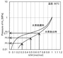
- 1 is an example of the PCT characteristic of the hydrogen storage alloy of the present invention.
- 1 is an example of the results of X-ray diffraction measurement on the hydrogen storage alloy of the present invention.
- FIG. 1 is a partially cutaway perspective view showing an example of the battery.
- an alkaline storage battery 10 is a storage battery having an electrode group including a nickel positive electrode 1 having nickel hydroxide (Ni(OH) 2 ) as a main positive electrode active material, a negative electrode 2 including a hydrogen storage alloy having a hydrogen storage alloy (MH) according to this embodiment as a negative electrode active material, and a separator 3, in a housing 4 together with an electrolyte layer (not shown) filled with an alkaline electrolyte.
- Ni(OH) 2 nickel hydroxide
- MH hydrogen storage alloy
- separator 3 in a housing 4 together with an electrolyte layer (not shown) filled with an alkaline electrolyte.
- the alkaline storage battery 10 is a so-called nickel-metal hydride battery (Ni-MH battery, hereafter also referred to as “nickel-metal hydride battery”), in which the following reaction occurs:
- the hydrogen storage alloy for use in the negative electrode of the alkaline storage battery according to this embodiment will be described below.
- the hydrogen storage alloy for alkaline storage batteries according to this embodiment (hereinafter also referred to as "hydrogen storage alloy”) is a hydrogen storage alloy for use in alkaline storage batteries, characterized in that the hydrogen storage alloy has a total of A2B7 type structure, A5B19 type structure, and AB3 type structure as its main phases, and is represented by the following general formula (1):
- R and the subscripts a, b, c, d, e, f, and g are R: Sm and/or Ce; 0 ⁇ a ⁇ 0.12, 0 ⁇ b ⁇ 0.12, 0.13 ⁇ c ⁇ 0.27, 3.20 ⁇ d+e+f+g ⁇ 3.75, 0 ⁇ e ⁇ 0.14, 0 ⁇ f ⁇ 0.05 0 ⁇ g ⁇ 0.35 Represents.
- the crystal structures of the A 2 B 7 type structure, the A 5 B 19 type structure and the AB 3 type structure are Ce 2 Ni 7 type and Gd 2 Co 7 type, Pr 5 Co 19 type and Ce 5 Co 19 type, and CeNi 3 type and PuNi 3 type, respectively.
- the hydrogen storage alloy is preferably a hydrogen storage alloy for alkaline storage batteries in which the general formula (1) further satisfies the following condition:
- the subscripts a, b, c, d, e, f, and g in the general formula (1) each represent 0 ⁇ a ⁇ 0.10, 0 ⁇ b ⁇ 0.10, 0.14 ⁇ c ⁇ 0.26, 3.25 ⁇ d+e+f+g ⁇ 3.70, 0 ⁇ e ⁇ 0.13, 0 ⁇ f ⁇ 0.04 0 ⁇ g ⁇ 0.30 Represents.
- the hydrogen storage alloy represented by general formula (1) When used as the negative electrode of an alkaline storage battery, the hydrogen storage alloy represented by general formula (1) imparts high discharge capacity and charge/discharge cycle life characteristics to the alkaline storage battery. Therefore, the hydrogen storage alloy represented by general formula (1) contributes to achieving smaller, lighter, and more durable alkaline storage batteries.
- Rare earth element La 1-a-b Y a R b (wherein 0 ⁇ a ⁇ 0.12, 0 ⁇ b ⁇ 0.12, preferably 0 ⁇ a ⁇ 0.10, 0 ⁇ b ⁇ 0.10)
- the hydrogen storage alloy according to this embodiment contains rare earth elements as the A component elements of the A2B7 type structure, A5B19 type structure, and AB3 type structure.
- the rare earth elements require two elements, La and Y, as basic components that provide hydrogen storage capacity. Since La and Y have different atomic radii, the hydrogen equilibrium pressure can be controlled by the component ratio, and the hydrogen equilibrium pressure proportional to the battery voltage can be set arbitrarily.
- the atomic ratio a value of Y in the rare earth elements is in the range of more than 0 and 0.12 or less. Within this range, it is easy to set the hydrogen equilibrium pressure suitable for an alkaline storage battery, and the hydrogen storage alloy has good corrosion resistance and is less likely to pulverize, resulting in high durability of the alkaline storage battery. If the a-value exceeds 0.12, the hydrogen storage alloy will be pulverized due to hydrogen absorption and release, and the durability of the alkaline storage battery will gradually decrease even if the alloy has an effect of improving corrosion resistance.
- the a-value is preferably 0.10 or less, and more preferably 0.003 or more.
- Y plays a major role in improving the durability of the hydrogen storage alloy by being present as an oxide or hydroxide in a surface layer composed of an oxide layer or hydroxide layer present on at least a part of the surface of the hydrogen storage alloy.
- R is either or both of Ce and Sm, and together with Y, contributes to the control of hydrogen equilibrium pressure and improvement of the corrosion resistance of the hydrogen storage alloy.
- the total atomic ratio b value of R among rare earth elements is in the range including 0 and not exceeding 0.12. Considering the control of hydrogen equilibrium pressure and durability of Y and R combined, if the b value exceeds 0.12, pulverization of the hydrogen storage alloy due to hydrogen absorption and release is promoted, and the durability of the alkaline storage battery may decrease.
- the b value is preferably 0.10 or less, and more preferably 0.005 or more.
- R is essential along with Y, that is, it is preferable that either Ce or Sm or both are essential, and it is even more preferable to use Ce.
- the b value it is preferable for the b value to be 0.10 or less in terms of controlling the hydrogen absorption/release characteristics of the hydrogen storage alloy, which are related to the battery characteristics.
- compositions with a high La content the discharge capacity of an alkaline storage battery is increased, and when La is combined with other elements, the discharge capacity characteristics of the alkaline storage battery are further improved.
- Pr and Nd are not actively used as rare earth elements, but may be included at the unavoidable impurity level.
- Mg Mgc (where 0.13 ⁇ c ⁇ 0.27, preferably 0.14 ⁇ c ⁇ 0.26) Mg is an essential element in this embodiment constituting the A component elements of the A2B7 type structure, A5B19 type structure, and AB3 type structure. Mg contributes to improving the discharge capacity characteristics and charge/discharge cycle life characteristics of an alkaline storage battery using a hydrogen storage alloy.
- the c value representing the atomic ratio of Mg in the A component is in the range of 0.13 to 0.27. If the value c is less than 0.13, the hydrogen release ability of the hydrogen storage alloy decreases, resulting in a decrease in the discharge capacity of the alkaline storage battery.
- the value of c exceeds 0.27, pulverization of the hydrogen storage alloy, particularly accompanying hydrogen storage and release, is promoted, and the charge-discharge cycle life characteristics, i.e., durability, of the alkaline storage battery is deteriorated.
- the value of c is in the range of 0.14 to 0.26.
- Ni d Ni is a main element in the B component of the A 2 B 7 type structure, the A 5 B 19 type structure and the AB 3 type structure.
- the atomic ratio d value of Ni to the A component will be described later.
- Al Al e (wherein, when Fe is essential, 0 ⁇ e ⁇ 0.14; when Fe is not essential, 0.03 ⁇ e ⁇ 0.13)
- Al is an element contained as the B component in the A2B7 type structure, the A5B19 type structure, and the AB3 type structure.
- Al is effective in adjusting the hydrogen equilibrium pressure related to the battery voltage, and can improve the corrosion resistance and durability of the hydrogen storage alloy, i.e., is effective in improving the charge/discharge cycle life characteristics of the alkaline storage battery.
- the e value which represents the atomic ratio of Al to the A component, is in the range of 0.03 or more and 0.14 or less.
- the corrosion resistance of the hydrogen storage alloy becomes insufficient, and as a result, the charge/discharge cycle life characteristics of the alkaline storage battery becomes insufficient.
- the e value exceeds 0.14, the discharge capacity of the alkaline storage battery decreases, and the hydrogen storage alloy is pulverized due to the hydrogen storage and release, resulting in problems with its durability.
- the preferred e value is in the range of 0.04 to 0.13.
- the hydrogen storage alloy contains Fe as an essential element as the B component, the corrosion resistance effect of the hydrogen storage alloy imparted by Al can be realized by Fe, and therefore the value of e is in the range of 0 to 0.13.
- the Al content of the alloy is sufficient on the lower side of the range of the present embodiment, and therefore the Al content of the hydrogen storage alloy can be reduced, and the discharge capacity of the alkaline storage battery can be increased accordingly.
- Cr Crf (where 0 ⁇ f ⁇ 0.05, preferably 0 ⁇ f ⁇ 0.04)
- Cr is an element contained as an element of the B component in the A2B7 type structure, the A5B19 type structure, and the AB3 type structure.
- Cr is effective in adjusting the hydrogen equilibrium pressure related to the battery voltage, and contributes to improving the corrosion resistance of the hydrogen storage alloy together with Al.
- it is effective in improving the durability of the alkaline storage battery, that is, the charge/discharge cycle life characteristics of the alkaline storage battery.
- the f value representing the atomic ratio of Cr to the A component is in the range of 0 to 0.05.
- Cr is not essential, but the synergistic effect with Y and Al enhances the corrosion resistance effect of the hydrogen storage alloy, improving its durability. However, if the amount of Cr exceeds 0.05 in terms of f-value, cracking of the hydrogen storage alloy due to hydrogen absorption and release is promoted, resulting in a decrease in durability of the alkaline storage battery, and the charge-discharge cycle life characteristics of the alkaline storage battery becoming insufficient.
- the f-value is preferably 0.04 or less, and more preferably 0.003 or more.
- the Cr content of the alloy is sufficient on the lower side of the range of the present embodiment, and therefore the Cr content of the hydrogen storage alloy can be reduced, thereby increasing the discharge capacity of the alkaline storage battery.
- Fe Fe g (where 0 ⁇ g ⁇ 0.35) Fe is contained as component B of a hydrogen storage alloy having a main phase of either one or both of an A2B7 type crystal structure and an A5B19 type crystal structure. That is, Fe may be contained as an essential element of the hydrogen storage alloy according to the present invention. Fe is effective in controlling the hydrogen equilibrium pressure related to the battery voltage of an alkaline storage battery, and can significantly improve corrosion resistance, and is effective in improving the durability of the hydrogen storage alloy, i.e., the charge/discharge cycle life characteristics of an alkaline storage battery. By using Fe and Y as essential constituent elements of the hydrogen storage alloy according to the present invention, the hydrogen equilibrium pressure can be easily controlled to a level suitable for alkaline storage batteries, and high corrosion resistance, high durability and low cost can be achieved.
- the g value which represents the atomic ratio of Fe in the general formula (1), is in the range of 0 or more and 0.35 or less. If the g-value exceeds 0.35, the discharge capacity of the alkaline storage battery will decrease.
- the preferred g-value is greater than 0 and equal to or less than 0.30.
- the hydrogen storage alloy used in the negative electrode is called a reservoir, and is 20 to 30 percent more than usual, assuming alkaline corrosion of the hydrogen storage alloy by the alkaline solution used as the electrolyte.
- an alkaline storage battery equipped with the hydrogen storage alloy according to this embodiment has little deterioration in its discharge capacity, so that it is possible to significantly reduce the amount of hydrogen storage alloy used in this portion, which corresponds to the reservoir and is used in excess in anticipation of alkaline corrosion.
- Ratio of component A to component B 3.20 ⁇ d+e+f+g ⁇ 3.75 (preferably 3.25 ⁇ d+e+f+g ⁇ 3.70)
- the stoichiometric ratio which is the molar ratio of the B component ( Ni , Al and Cr) to the A component in the A2B7 type structure, the A5B19 type structure and the AB3 type structure, i.e., the value of d+e+f+g represented by the general formula, is in the range of 3.20 or more and 3.75 or less. If the value of d+e+f+g is less than 3.20, the subphase, ie, the AB2 phase, increases in the hydrogen storage alloy, and the discharge capacity of the alkaline storage battery in particular decreases.
- the AB2 phase produced within the composition range of the hydrogen storage alloy according to this embodiment has the property of absorbing hydrogen but making it difficult to release it, resulting in a decrease in the amount of hydrogen absorbed by the hydrogen storage alloy and a decrease in the discharge capacity of the alkaline storage battery.
- the AB5 phase increases in the hydrogen storage alloy, and the alloy powder of the hydrogen storage alloy is pulverized due to hydrogen absorption and release.
- the durability of the hydrogen storage alloy i.e., the cycle life of the alkaline storage battery, decreases.
- the value of d+e+f+g is preferably in the range of 3.25 to 3.70.
- the hydrogen storage alloy according to this embodiment has the above-mentioned composition, and it is preferable that the alloy particles obtained by pulverizing the hydrogen storage alloy have a 50% transmittance particle size D50 based on mass in the range of 3 ⁇ m or more and 30 ⁇ m or less, and a 90% transmittance particle size D90 based on mass in the range of 8 ⁇ m or more and 60 ⁇ m or less.
- the hydrogen storage alloy according to this embodiment has excellent hydrogen absorption/desorption properties and durability, because the average particle size of the finely pulverized alloy particles is set within a predetermined range.
- the hydrogen storage alloy of this embodiment preferably has a hydrogen storage capacity H/M (H is the number of hydrogen atoms, and M is the number of metal atoms) of 0.94 or more when the hydrogen pressure is increased to 1 MPa at 80°C. Furthermore, it is preferable that the hydrogen pressure (P0.5, hereinafter referred to as hydrogen equilibrium pressure) when the hydrogen storage capacity (H/M: atomic ratio of hydrogen atoms (H) to metal atoms (M)) during hydrogen release at 80°C is 0.5 is 0.025 MPa or more and 0.12 MPa or less. If the hydrogen storage capacity is within this range, the battery can operate without problems under various temperature conditions.
- PCT Pressure-Composition-Temperature
- the discharge capacity is largely determined by the composition of the hydrogen storage alloy.
- the durability of the hydrogen storage alloy depends on the degree of pulverization of the hydrogen storage alloy due to hydrogen absorption and release, or the elution of the hydrogen storage alloy components into an alkaline aqueous solution. This depends on the composition of the hydrogen storage alloy and the proportion and properties of the alloy phases that are generated based on heat treatment. From this technical point of view, in order to proceed with the development of hydrogen storage alloys that satisfy the demand for high durability, extensive research was conducted into evaluating the cracking tendency of hydrogen storage alloys due to repeated hydrogen absorption and desorption.
- the alloy particles are mechanically crushed into alloy particles, and the alloy particles are sieved to have a size of 150 ⁇ m or more and 1 mm or less.
- Hydrogen is pressurized to 3 MPa at 80° C. to cause the alloy to absorb hydrogen, and then the hydrogen is released from the alloy by evacuating it to a vacuum.
- the particle size distribution of the alloy particles was evaluated, and the mean particle size by volume (MV) was expressed as a representative value, which led to the discovery of a hydrogen storage alloy with particularly excellent durability.
- the detailed conditions are as follows.
- "sieved to 150 ⁇ m or more and 1 mm or less” means that the particles are on a sieve with 150 ⁇ m openings and are below a sieve with 1 mm openings.
- hydrogen absorption/release measurements are performed at hydrogen pressures ranging from 0.01 to 3 MPa, just like the first cycle.
- the difference between the first and fifth hydrogen absorption/release and the second to fourth hydrogen absorption/release is the processing time.
- the second to fourth hydrogen absorption/release require a shorter time because the hydrogen pressure is increased to 3 MPa in one go.
- the volume average particle diameter MV of the alloy particles obtained by pulverizing the hydrogen storage alloy after repeated hydrogen absorption/release is preferably in the range of 75 ⁇ m or more. If the volume average particle diameter MV of the alloy particles is in this range, it is preferable because the hydrogen storage alloy does not pulverize due to charging/discharging when actually incorporating the hydrogen storage alloy into an alkaline storage battery. In other words, it can be seen that the hydrogen storage alloy according to this embodiment has excellent durability, combined with good corrosion resistance in alkaline solutions.
- the volume average particle size MV of the alloy particles may be measured by a laser diffraction particle size distribution measuring device, and as the measuring device, for example, Model MT3300EXII manufactured by Microtrac-Bell Inc. can be used.
- the value of the hydrogen storage capacity index H/M (atomic ratio of hydrogen H to metal M) at 1 MPa obtained from PCT measurement at 80° C. is 0.94 or more. If the hydrogen storage capacity is within this range, an alkaline storage battery equipped with a negative electrode containing such a hydrogen storage alloy as a negative electrode active material can maintain a sufficient discharge capacity, and therefore it can be said that a highly durable hydrogen storage alloy is obtained.
- the slope B of the plateau which is the value calculated by [log(P0.7/P0.3)]/0.4 shown in the above relational formula (A), is in the range of 1.3 to 3.0. If the slope B of the plateau is smaller than 1.3, the expansion of the crystal lattice of the hydrogen storage alloy during hydrogen storage tends to occur in one direction, in other words, it tends to expand and contract anisotropically. Therefore, the strain generated in the crystal lattice of the hydrogen storage alloy may promote cracking of the hydrogen storage alloy. On the other hand, if the slope B of the plateau exceeds 3.0, the amount of hydrogen storage will be difficult to increase even when hydrogen pressure is applied, and as a result, the discharge capacity of the alkaline storage battery may decrease. Preferably, the slope B of the plateau is 1.35 or more and 2.95 or less.
- the ratio of the diffraction intensity ( ⁇ ) of the (101) plane of the AB5 phase to the diffraction intensity ( ⁇ ) of the strongest diffraction peak in the diffraction angle range of 40 to 45° is preferably ⁇ / ⁇ 0.08. If the ⁇ / ⁇ ratio exceeds 0.08, the charge/discharge cycle life characteristics of the alkaline storage battery may be deteriorated. More preferably, the ⁇ / ⁇ ratio is 0.05 or less.
- Fig. 3 is a graph showing an example of the results of X-ray diffraction measurement of the hydrogen storage alloy according to this embodiment.
- the ⁇ / ⁇ ratio is the ratio of the height of the diffraction peak indicated by ⁇ to the height of the strongest diffraction peak indicated by *. If the ⁇ / ⁇ ratio is in this range, the ratio of the AB5 phase that reduces the durability of the hydrogen storage alloy is low, and therefore the durability of the hydrogen storage alloy can be expected to be improved.
- the X-ray diffraction measurement conditions are as follows: A hydrogen storage alloy powder consisting of alloy particles crushed to a particle size of 75 ⁇ m or less is set in a sample holder, and measurement is performed using only a k ⁇ filter under the following conditions with Cu as the target.
- the hydrogen storage alloy of the present invention On the surface of the hydrogen storage alloy of the present invention, a surface layer consisting of an oxide layer or hydroxide layer containing an appropriate amount of Y as shown in the above general formula (1) is formed in close contact with the alloy particles constituting the hydrogen storage alloy. Therefore, the hydrogen storage alloy of the present invention has excellent durability due to the presence of the surface layer consisting of an oxide layer or hydroxide layer containing an appropriate amount of Y.
- This surface layer is formed by turning elements such as Y already contained inside the hydrogen storage alloy into metal oxides or metal hydroxides during the process of producing the negative electrode active material, and being contained as an oxide layer or hydroxide layer on the surface of the hydrogen storage alloy.
- the surface layer consisting of an oxide layer or hydroxide layer containing Y preferably contains Mg and Al, "mainly rare earth elements" contained in the hydrogen storage alloy.
- mainly rare earth elements means that the oxide layer or hydroxide layer formed on the surface of the hydrogen storage alloy is made up of oxides or hydroxides of rare earth elements that account for more than half by mass.
- the BET specific surface area of the hydrogen storage alloy is preferably larger than 0.5 m 2 /g, more preferably 0.55 to 7.0 m 2 /g, and even more preferably 0.6 to 4.0 m 2 /g. If the BET specific surface area is within this range, the hydrogen storage alloy is suitable for use as a negative electrode active material contained in a negative electrode of an alkaline storage battery.
- the pore volume of the hydrogen storage alloy having a surface layer is preferably 0.013 cm 3 /g or less, and the average pore diameter is preferably 40 nm or less. More preferably, the pore volume is in the range of 0.0025 to 0.0125 cm 3 /g, and the average pore diameter is in the range of 10 to 35 nm. If the pore volume exceeds 0.013 cm 3 /g and the average pore diameter exceeds 40 nm, which are too large, the density of the surface layer becomes low, the probability of cracking increases, and the durability of the hydrogen storage alloy may decrease.
- the pore volume is less than 0.0025 cm 3 /g and the average pore diameter is less than 10 nm, the impregnation of the electrolyte into the surface layer of the hydrogen storage alloy is insufficient, and the hydrogen storage and release properties are deteriorated.
- the thickness of the surface layer consisting of an oxide layer or hydroxide layer in close contact with the alloy particles is 500 nm or less, and preferably in the range of 50 to 450 nm. If the thickness of the surface layer is too thick, exceeding 500 nm, the impregnation of the electrolyte into the surface layer of the hydrogen storage alloy is insufficient, and the hydrogen storage and release properties may be deteriorated. On the other hand, if a surface layer is not formed on the surface of the hydrogen storage alloy of the present invention, the corrosion resistance of the hydrogen storage alloy is significantly deteriorated.
- the hydrogen storage alloy according to this embodiment achieves both high output and high durability by suppressing the durability of the alloy itself, i.e., the pulverization of the alloy that accompanies hydrogen absorption and release. Furthermore, this hydrogen storage alloy is likely to form a surface layer on the surface of the alloy particles that has both excellent hydrogen absorption and release characteristics and alkaline corrosion resistance. For this reason, the hydrogen storage alloy according to this embodiment is particularly excellent in durability. In other words, an alkaline storage battery that uses this hydrogen storage alloy as the negative electrode active material achieves high output characteristics while also having excellent charge and discharge cycle characteristics.
- the hydrogen storage alloy of this embodiment is prepared by weighing out rare earth elements (Sm, Y, La, Ce, etc.) and metallic elements such as magnesium (Mg), nickel (Ni), aluminum (Al), chromium (Cr), and iron (Fe) to obtain a predetermined molar ratio, and then putting these raw materials into an alumina crucible placed in a high-frequency induction furnace and melting them under an inert gas atmosphere such as argon gas, and then casting the melt into a mold to produce an ingot of the hydrogen storage alloy.
- the hydrogen storage alloy of this embodiment may be directly produced as a flake-shaped sample having a thickness of about 200 to 500 ⁇ m by strip casting.
- the hydrogen storage alloy of this embodiment contains Mg, which has a low melting point and high vapor pressure, as its main component. If all the alloy component raw materials are melted at once, the Mg will evaporate, making it difficult to obtain an alloy with the desired chemical composition. Therefore, when manufacturing the hydrogen storage alloy of this embodiment by a melting method, it is preferable to first melt the other alloy components except Mg, and then add Mg raw materials such as metallic Mg and Mg alloys to the molten metal. This melting process is preferably performed under an inert gas atmosphere such as argon or helium, and more specifically, it is preferable to perform the melting process under a reduced pressure atmosphere of 0.05 to 0.2 MPa in an inert gas containing 80 vol% or more of argon gas. The alloy melted under the above conditions is then preferably cast into a water-cooled mold and solidified to form an ingot of the hydrogen storage alloy.
- Mg which has a low melting point and high vapor pressure
- the melting point (T m ) of each of the obtained hydrogen storage alloy ingots is measured using a DSC (differential scanning calorimeter) because the hydrogen storage alloy of this embodiment is preferably subjected to a heat treatment in which the ingot after casting is held in an atmosphere of either an inert gas such as argon or helium, or nitrogen gas, or a mixed gas thereof, at an appropriate temperature of 800° C. or higher and lower than the melting point (T m ) of the alloy for 3 to 50 hours.
- an inert gas such as argon or helium, or nitrogen gas, or a mixed gas thereof
- the total ratio of the A2B7 type, A5B19 type and AB3 type crystal structures as main phases in the hydrogen storage alloy can be set to 70 mass% or more, preferably the total ratio of the A2B7 type and A5B19 type crystal structures can be set to 70 mass% or more, and the AB2 phase and AB5 phase , which are subphases formed during casting , can be reduced or eliminated. It can be confirmed by X-ray diffraction measurement using Cu-K ⁇ radiation that the crystal structure of the main phase of the obtained hydrogen storage alloy is an A2B7 type structure, an A5B19 type structure, or an AB3 type structure.
- the main phase of the hydrogen storage alloy means more than 50 mass%, and preferably 70 mass% or more.
- the heat treatment temperature is less than 800°C, the diffusion of the elements is insufficient, and the subphase may remain, which may result in a decrease in the discharge capacity of the battery and deterioration of the charge/discharge cycle characteristics.
- the heat treatment temperature is -20°C or more lower than the melting point Tm of the alloy ( Tm -20°C or more), the crystal grains of the main phase may become coarse or partially melt, or the Mg component may evaporate, which may result in pulverization or a change in the chemical composition, resulting in a decrease in the amount of hydrogen absorption. Therefore, the heat treatment temperature is preferably in the range of 800°C to ( Tm -30°C).
- the holding time of the heat treatment is preferably 4 hours or more, and from the viewpoint of homogenizing the main phase of the hydrogen storage alloy and improving the crystallinity, it is more preferably 5 hours or more.
- the holding time exceeds 50 hours, the amount of evaporated Mg increases, causing a change in the chemical composition of the hydrogen storage alloy, which may result in the formation of an AB5 type subphase, and is not preferable because it may increase the manufacturing cost and cause a dust explosion due to evaporated Mg fine powder.
- the heat-treated hydrogen storage alloy is pulverized by either a dry method or a wet method.
- a dry method for example, a hammer mill or ACM pulverizer is used.
- a wet method a ball mill or attritor is used.
- wet pulverization is preferable because it can be produced safely.
- the particle size of the alloy particles to be pulverized is preferably in the range of 3 ⁇ m to 30 ⁇ m in terms of the 50% transmission rate particle size D50 based on mass, and more preferably in the range of 5 ⁇ m to 25 ⁇ m, in terms of the balance of battery characteristics such as output and cycle life characteristics. Furthermore, if the particle size distribution of the alloy particles is too wide, the above characteristics will deteriorate, so it is preferable that the 10% transmission rate particle size D10 based on mass is in the range of 0.5 ⁇ m to 15 ⁇ m, and the 90% transmission rate particle size D90 is in the range of 8 ⁇ m to 60 ⁇ m.
- the 10% transmission rate particle size D10 is in the range of 1 ⁇ m to 10 ⁇ m
- the 90% transmission rate particle size D90 is in the range of 10 ⁇ m to 50 ⁇ m.
- the particle size of the alloy particles can be controlled by adjusting conditions such as the diameter, amount, and rotation speed of the media.
- the particle size distributions D50, D10 and D90 of the above-mentioned alloy particles are values measured using a laser diffraction/scattering type particle size distribution measuring device, and as the measuring device, for example, the MT3300EXII type manufactured by Microtrack Bell, etc. can be used.
- the hydrogen storage alloy according to the present embodiment is an alloy whose main phase is an A2B7 type crystal structure, an A5B19 type crystal structure, or an AB3 type crystal structure.
- the A2B7 type crystal structure can be either of the hexagonal (2H) Ce2Ni7 phase and the rhombohedral ( 3R ) Gd2Co7 phase, but it is preferable that the former is contained in large amounts.
- the former is contained in a larger amount, and it is preferable that the combined amount of the A2B7 type crystal structure, the A5B19 type crystal structure and the AB3 type crystal structure is at least 70 mass% or more. More preferably, the combined amount of the A 2 B 7 crystal structure and the A 5 B 19 crystal structure is 70 mass % or more.
- the crystal structures of these hydrogen storage alloys can be evaluated by Rietveld analysis based on the results of X-ray diffraction measurement.
- a hydrogen storage alloy used as the negative electrode active material of this embodiment in which a layer of an oxide or hydroxide containing Y is adhered to the surface of the hydrogen storage alloy, it is preferable to actively oxidize the surface of the hydrogen storage alloy.
- a procedure for treating the hydrogen storage alloy in a suitable manner hereinafter referred to as a treatment method for the hydrogen storage alloy
- producing the hydrogen storage alloy of this embodiment for use as a negative electrode active material for an alkaline storage battery will be described.
- the method for treating hydrogen storage alloys is as follows: N-1) treating the hydrogen storage alloy with an alkaline aqueous solution; N-2) a step of oxidizing the surface of the hydrogen storage alloy after the step N-1); has. N-1)
- a step of treating the hydrogen storage alloy with an alkaline aqueous solution (hereinafter, simply referred to as "N-1) step") is not an essential step for oxidizing the hydrogen storage alloy, but as will be described later, by going through this step, it is possible to obtain a hydrogen storage alloy that can be more preferably used as the negative electrode active material according to the present embodiment.
- the hydrogen storage alloy used in step N-1) is a hydrogen storage alloy containing rare earth elements such as La, Y, Ce, Mg, Al and Ni, and having as its main phases the A2B7 type crystal structure, the A5B19 type crystal structure and the AB3 type crystal structure.
- N-1) When the hydrogen storage alloy is treated with an alkaline aqueous solution in which an alkali metal hydroxide is dissolved in the step, corrosion progresses from the surface of the alloy.
- rare earth elements, Mg, and Al which are easily oxidized and highly soluble in alkaline aqueous solutions among the components contained in the hydrogen storage alloy, are partially converted into oxides or hydroxides on the spot, and partially eluted from the surface of the hydrogen storage alloy.
- Ni remains in place because of its high corrosion resistance and low solubility in alkaline aqueous solutions, resulting in the formation of a layer of metal, oxide, and hydroxide on the surface of the hydrogen storage alloy.
- the surface layer newly formed on the surface of the hydrogen storage alloy is referred to as the surface treatment layer.
- the surface treatment layer is made of a metal oxide or an alkali metal hydroxide. It is believed that the presence of this surface treatment layer formed on the surface of the hydrogen storage alloy improves the performance of the hydrogen storage alloy used as the negative electrode active material of an alkaline storage battery.
- alkali metal hydroxides examples include lithium hydroxide, sodium hydroxide, and potassium hydroxide, with sodium hydroxide being preferred.
- an aqueous sodium hydroxide solution as the alkaline aqueous solution, the battery characteristics of the nickel-metal hydride battery, which is the alkaline storage battery according to this embodiment, may be optimized in some cases compared to the case where lithium hydroxide or potassium hydroxide is used.
- the alkaline aqueous solution is preferably a strong base.
- concentration of the alkali metal hydroxide in the alkaline aqueous solution is preferably in the range of 10 to 60% by mass, and more preferably in the range of 20 to 55% by mass.
- the N-1) step is preferably carried out by immersing the hydrogen storage alloy in an alkaline aqueous solution.
- the heating temperature is preferably in the range of 50 to 150°C, and more preferably in the range of 70 to 140°C.
- the heating time may be appropriately determined depending on the concentration of the alkaline aqueous solution, the heating temperature, and the stirring conditions, but is preferably in the range of 0.1 to 10 hours, and more preferably in the range of 0.2 to 5 hours.
- the relationship between the amount of the hydrogen storage alloy and the alkaline aqueous solution is preferably in the range of 1:0.5 to 1:10 by mass ratio, and more preferably in the range of 1:0.7 to 1:8. If the amount of the alkaline aqueous solution is too small, the surface treatment layer may not be sufficiently formed on the hydrogen storage alloy, while if the amount of the alkaline aqueous solution is too large, it will be disadvantageous in terms of cost.
- the alkaline aqueous solution contains rare earth elements, Mg, and Al that have been partially dissolved from the hydrogen storage alloy.
- the rare earth elements, Mg, and Al may adhere to the surface of the hydrogen storage alloy as hydroxides of the rare earth elements, Mg, and Al.
- the hydrogen storage alloy may be washed with water. Washing with water can remove the alkaline aqueous solution adhering to the surface of the hydrogen storage alloy.
- the mass ratio of the hydrogen storage alloy to the amount of water when washing with water is preferably 1:1 to 1:50, and more preferably 1:2 to 1:30.
- N-2) the step of oxidizing the surface of the hydrogen storage alloy after the above-mentioned N-1) step (hereinafter simply referred to as "N-2) step") will be described.
- the hydrogen storage alloy may be washed with water in the atmosphere after the treatment with the alkaline aqueous solution in the above-mentioned N-1) step, to obtain N-2) step.
- the N-2) step may be a method of exposing the hydrogen storage alloy to air and oxidizing the surface of the hydrogen storage alloy with oxygen in the air, or a method of contacting the hydrogen storage alloy with an oxidizing agent such as hydrogen peroxide and oxidizing it.
- the preferred negative electrode active material of this embodiment which is manufactured through steps N-1) and N-2), contains a layer on its surface in which a metal, an oxide, and a hydroxide are mixed.
- the preferred negative electrode active material of this embodiment can also be expressed as having a surface treatment layer on its surface in which a metal, an oxide, and a hydroxide are mixed.
- a surface layer can be formed on the surface of the hydrogen storage alloy of this embodiment, the surface layer being an oxide layer or hydroxide layer containing Y in at least a part thereof, thereby improving the corrosion resistance of the hydrogen storage alloy of this embodiment.
- the oxide or hydroxide contained in the surface treatment layer of the hydrogen storage alloy is preferably composed mainly of the rare earth elements contained in the hydrogen storage alloy, Mg, and Al.
- the pore volume of the hydrogen storage alloy on which the surface treatment layer made of this oxide layer or hydroxide layer is formed is 0.013 cm3 /g or less and the average pore diameter is 40 nm or less. If the pore volume exceeds 0.013 cm3 /g, the density of the surface treatment layer decreases and the probability of cracking increases, which may accelerate the corrosion of the hydrogen storage alloy due to immersion in an alkaline solution, i.e., the corrosion resistance of the alloy may decrease. If the average pore diameter is too large, exceeding 40 nm, the hydrogen storage alloy may be immersed in an alkaline solution excessively, which may accelerate the corrosion of the hydrogen storage alloy, i.e., the durability may decrease.
- the pore volume is less than 0.0025 cm /g and the average pore diameter is less than 10 nm, the impregnation of the electrolyte into the hydrogen storage alloy may be insufficient, and the hydrogen absorption/desorption characteristics of the alloy may be deteriorated.
- the pore volume is 0.0025 to 0.0125 cm /g and the average pore diameter is 10 to 35 nm.
- the surface layer formed on the surface of the hydrogen storage alloy according to this embodiment and consisting of an oxide layer or hydroxide layer containing Y in at least a part thereof is preferably 500 nm or less in thickness in close contact with the surface of the alloy particles. If the thickness of the surface layer exceeds 500 nm, the impregnation of the electrolyte into the hydrogen storage alloy may be insufficient, and the hydrogen absorption/desorption properties of the alloy may be deteriorated. On the other hand, if the hydrogen storage alloy according to this embodiment does not have a surface treatment layer formed at least partially, the corrosion resistance of the alloy is significantly reduced.
- the thickness of the surface layer is preferably 50 to 450 nm.
- the surface of the negative electrode active material was analyzed as follows.
- the surface treatment layer formed on the surface of the hydrogen storage alloy was observed using a transmission electron microscope.
- the negative electrode active material powder was mixed with an epoxy resin, and the resin was cured at 120° C. for 30 minutes to embed the negative electrode active material in the resin.
- a thin-film sample of 100 nm or less is obtained by a thin-film process using an argon beam.
- an ion slicer (EM09100 IS) manufactured by JEOL Ltd. is used, and the sample is polished thinly at an acceleration voltage of 6 kV until a few ⁇ m of pores are formed, and then finished at an acceleration voltage of 1.0 kV for 15 minutes.
- the obtained thin-film sample is observed on the alloy surface at an acceleration voltage of 200 kV using a transmission electron microscope (JEM2100F manufactured by JEOL Ltd.).
- JEM2100F manufactured by JEOL Ltd.
- JED2300 manufactured by JEOL Ltd.
- the volume of 1 mol of gas in the standard state is 22414 Ncm 3
- the molecular weight M of nitrogen is 28.013 g/mol
- the density ⁇ of nitrogen in the liquid phase is 0.808 g/cm 3 .
- the BET specific surface area of the hydrogen storage alloy used as the negative electrode active material according to this embodiment is preferably greater than 0.5 m 2 /g. If the BET specific surface area of the hydrogen storage alloy is less than this, the average pore size may become too large.
- the BET specific surface area of the hydrogen storage alloy is more preferably in the range of 0.55 to 7.0 m 2 /g, and even more preferably in the range of 0.6 to 4.0 m 2 /g.
- an acid treatment step may be combined.
- the surface of the hydrogen storage alloy is acid-treated using an aqueous solution of nitric acid, sulfuric acid, hydrochloric acid, etc.
- the acid treatment step provides a hydrogen storage alloy that exhibits better battery characteristics, particularly durability and low-temperature discharge characteristics. This is because the precipitation of a large number of Ni fine particles on the surface of the hydrogen storage alloy improves the catalytic action of the hydrogen storage alloy, facilitating hydrogen storage and release. Therefore, the discharge characteristics at low temperatures are improved, and the increase in the amount of Ni fine particles on the surface improves corrosion resistance and durability.
- an alkaline storage battery 10 of the present invention is composed of at least a positive electrode 1, a negative electrode 2, a separator 3, and a casing 4 (battery case) that is filled with an electrolyte and contains them. The details will be described below.
- the positive electrode 1 is usually composed of a positive electrode active material layer and a positive electrode current collector.
- the positive electrode active material layer contains at least a positive electrode active material.
- the positive electrode active material layer may further contain at least one of a positive electrode additive, a conductive assistant, a binder, and a thickener.
- the positive electrode active material is not particularly limited as long as it functions as a battery when combined with the above-mentioned hydrogen storage alloy (negative electrode material), and examples thereof include simple metals, alloys, hydroxides, and the like.
- the positive electrode active material may contain nickel oxide and be mainly composed of nickel oxyhydroxide and/or nickel hydroxide.
- the amount of nickel oxide in the positive electrode active material is, for example, 90 to 100 mass %, or may be 95 to 100 mass %.
- the average particle size of the nickel oxide may be appropriately selected, for example, from the range of 3 to 35 ⁇ m, and is preferably in the range of 3 to 25 ⁇ m.
- the positive electrode active material is preferably a positive electrode active material having a layer of a conductive assistant formed therearound in advance, or a positive electrode active material having a layer of cobalt oxyhydroxide formed therearound in advance and doped with an alkali metal.
- the positive electrode additive is added to the positive electrode to improve the battery characteristics of the nickel-metal hydride battery.
- the positive electrode additive is not limited as long as it is used as a positive electrode additive for the nickel metal hydride battery.
- Specific positive electrode additives include niobium compounds such as Nb 2 O 5 , tungsten compounds such as WO 2 , WO 3 , Li 2 WO 4 , Na 2 WO 4 and K 2 WO 4 , ytterbium compounds such as Yb 2 O 3 , titanium compounds such as TiO 2 , yttrium compounds such as Y 2 O 3 , zinc compounds such as ZnO, calcium compounds such as CaO, Ca(OH) 2 and CaF 2 , and other rare earth oxides.
- the conductive additive is not particularly limited as long as it is a material that can impart electronic conductivity to the positive electrode, and examples of such additives include metal powders such as Ni powder, oxides such as cobalt oxide, graphite, and carbon materials such as carbon nanotubes.
- the amount of conductive additive added is not particularly limited, but is preferably in the range of 0.1 to 50 parts by mass, and more preferably in the range of 0.1 to 30 parts by mass, per 100 parts by mass of the positive electrode active material.
- the binder plays a role in binding the active material and the like to the surface of the current collector.
- the binder there are no limitations on the binder, so long as it is used as an electrode binder for nickel-metal hydride batteries.
- binders include fluorine-containing resins such as polyvinylidene fluoride, polytetrafluoroethylene, and fluorine rubber, polyolefin resins such as polypropylene and polyethylene, imide resins such as polyimide and polyamideimide, cellulose derivatives such as carboxymethyl cellulose, methyl cellulose, and hydroxypropyl cellulose, copolymers such as styrene butadiene rubber, and (meth)acrylic resins such as polyacrylic acid, polyacrylic acid esters, polymethacrylic acid, and polymethacrylic acid esters that contain (meth)acrylic acid derivatives as monomer units.
- the amount of binder may be, for example, 7 parts by mass or less relative to 100 parts by mass
- examples of the thickener include carboxymethylcellulose and its modified products (including salts such as Na salt), cellulose derivatives such as methylcellulose, saponified polymers having vinyl acetate units such as polyvinyl alcohol, and polyalkylene oxides such as polyethylene oxide. These thickeners may be used alone or in combination of two or more.
- the amount of the thickener is, for example, 5 parts by mass or less, and may be in the range of 0.01 to 3 parts by mass, or may be in the range of 0.05 to 1.5 parts by mass, per 100 parts by mass of the positive electrode active material.
- the material of the positive electrode current collector can be, for example, stainless steel, aluminum, nickel, iron, titanium, etc.
- the shape of the positive electrode current collector can be, for example, foil, mesh, porous, etc., and any shape is acceptable.
- the positive electrode can be formed by attaching a positive electrode mixture containing a positive electrode active material to a support (positive electrode current collector).
- the positive electrode mixture is usually prepared by forming a paste from the above-mentioned positive electrode active material, positive electrode additive, conductive assistant, and binder.
- As the dispersion medium water, an organic medium, or a mixed medium of two or more media selected from these can be used. If necessary, a positive electrode additive, conductive assistant, binder, thickener, etc. may be added, but these (especially the positive electrode additive, binder, and thickener) do not necessarily have to be added.
- the positive electrode may be formed by applying the positive electrode mixture paste to a support, depending on the shape of the support, or by filling the pores in the support.
- the positive electrode can be formed by applying or filling the paste onto a support, drying to remove the dispersion medium, and compressing the resulting dried material in the thickness direction (e.g., rolling between a pair of rolls).
- the negative electrode 2 is usually composed of a negative electrode active material layer and a negative electrode current collector.
- the negative electrode active material layer must contain at least the above-described hydrogen storage alloy of the present invention as a negative electrode active material.
- the negative electrode active material layer may further contain at least one of a negative electrode additive, a conductive assistant, a binder, and a thickener.
- the negative electrode additive is added to the negative electrode to improve the battery characteristics of the nickel-hydride battery.
- the negative electrode additive is not limited as long as it is used as a negative electrode additive for the nickel-hydride battery.
- Specific examples of the negative electrode additive include rare earth element fluorides such as CeF3 and YF3 , bismuth compounds such as Bi2O3 and BiF3 , indium compounds such as In2O3 and InF3 , and the compounds exemplified as the positive electrode additive.
- the conductive additive is not particularly limited as long as it is a material that can impart electronic conductivity, and examples of such additives include metal powders such as Ni powder, oxides such as cobalt oxide, graphite, and carbon materials such as carbon nanotubes.
- the amount of conductive additive added is not particularly limited, but is preferably in the range of 0.1 to 50 parts by mass, and more preferably in the range of 0.1 to 30 parts by mass, per 100 parts by mass of the hydrogen storage alloy powder.
- binders include synthetic rubbers such as styrene-butadiene rubber (SBR), celluloses such as carboxymethyl cellulose (CMC), polyols such as polyvinyl alcohol (PVA), and fluororesins such as polyvinylidene fluoride (PVDF).
- SBR styrene-butadiene rubber
- CMC carboxymethyl cellulose
- PVA polyvinyl alcohol
- PVDF polyvinylidene fluoride
- the amount of binder may be, for example, 7 parts by mass or less per 100 parts by mass of the hydrogen storage alloy powder, and may be in the range of 0.01 to 5 parts by mass, or even 0.05 to 2 parts by mass.
- Examples of the material of the negative electrode current collector include steel, stainless steel, aluminum, nickel, iron, titanium, carbon, etc.
- the shape of the negative electrode current collector may be, for example, a foil shape, a mesh shape, a porous shape, or any other shape.
- the components contained in the negative electrode active material layer, such as the negative electrode active material are made into a paste to prepare a negative electrode paste.
- the negative electrode paste is prepared by adding the above-mentioned negative electrode active material, negative electrode additive, conductive assistant, binder, thickener, etc. to a solvent.
- This negative electrode for a nickel-metal hydride battery is produced by forming a negative electrode paste containing the hydrogen storage alloy powder of the present invention as a negative electrode active material into a predetermined shape and supporting the formed negative electrode paste with a negative electrode core material (negative electrode current collector), or by preparing a negative electrode paste containing the above-mentioned hydrogen storage alloy powder, applying this to a negative electrode current collector, and drying it.
- the electrolyte layer is a layer formed between the positive electrode and the negative electrode and containing an aqueous electrolyte.
- the aqueous electrolyte refers to an electrolyte that mainly uses water as a solvent, and the solvent may contain other substances than water.
- the ratio of water to the entire solvent of the electrolyte may be 50 mol% or more, 70 mol% or more, 90 mol% or more, or 100 mol%.
- the aqueous electrolyte is preferably an alkaline aqueous solution.
- solutes in the alkaline aqueous solution include potassium hydroxide (KOH) and sodium hydroxide (NaOH), which may also contain LiOH.
- the concentration of the solute in the aqueous electrolyte is preferably 2 to 10 mol/L, more preferably 3 to 9 mol/L, and even more preferably 4 to 8 mol/L.
- the aqueous electrolyte may contain known additives that are used in electrolytes for nickel hydride batteries.
- the electrolyte layer has a separator 3.
- the separator 3 By installing the separator 3, short circuits can be effectively prevented.
- the separator 3 include nonwoven fabrics and porous membranes that contain resins such as sulfonated polyethylene and polypropylene.
- the case 4 is a battery case (cell container) that houses the positive electrode 1, the negative electrode 2, and the separator 3 and is filled with an electrolyte.
- the material may be any material that is stable and not corroded by the electrolyte, and can retain the gas (oxygen or hydrogen) temporarily generated during charging and the electrolyte without leaking to the outside, and for example, a metal case or a resin case is generally used.
- the case 4 may have a structure in which the periphery of the stack is sealed with a frame-shaped resin.
- the alkaline storage battery 10 of the present invention is usually a secondary battery. Therefore, since it can be repeatedly charged and discharged, it is suitable, for example, as a battery for use in a vehicle.
- the alkaline storage battery 10 is not limited to being used only as a battery for a hybrid vehicle that supplies power to a motor for driving the vehicle.
- the alkaline storage battery 10 may also be used to supply power to a starter motor for restarting the engine of a vehicle having an idling stop function.
- the secondary battery also includes a secondary battery used as a primary battery (used for only one discharge after charging).
- the shape of the battery may be, for example, a coin type, a laminate type, a cylindrical type, a square type, or the like, and any shape may be used.
- the vehicle of the present invention is equipped with an alkaline storage battery using the above-mentioned hydrogen storage alloy in the negative electrode as a power supply source for a motor.
- the alkaline storage battery of the present invention which is significantly smaller and lighter than conventional batteries, the vehicle of the present invention can improve driving performance, reduce fuel consumption, and extend the cruising distance.
- Example 1 Evaluation cells having negative electrodes in which alloys (hydrogen storage alloys) No. 1 to 70 having the component compositions shown in Tables 1-1 to 1-4 below were used as negative electrode active materials were prepared in the manner described below, and experiments were conducted to evaluate the characteristics of the negative electrodes.
- alloys No. 1 to 33 shown in Tables 1-1 to 1-4 are alloy examples (invention examples) that meet the conditions of the present invention
- alloys No. 34 to 70 are alloy examples (comparative examples) that do not meet the conditions of the present invention.
- alloy No. 34 of the comparative example was used as a reference alloy for evaluating the characteristics of the cells.
- the heat-treated alloy ingot was then coarsely pulverized, further coarsely pulverized in a wet ball mill, finely pulverized to a 50% passing particle size D50 of 16 ⁇ m by mass, and filtered to obtain a finely pulverized filtered product.
- the hydrogen storage alloy was treated with an alkaline aqueous solution as follows: 50 parts by mass of an aqueous sodium hydroxide solution containing 48% by mass of sodium hydroxide was added to 50 parts by mass of the finely pulverized filtered product of Example 1 to prepare a suspension.
- the suspension was heated to 100° C. and held for 2 hours, and then cooled to room temperature.
- the suspension was allowed to stand, the supernatant liquid was removed, and the hydrogen storage alloy was separated from the alkaline aqueous solution. 800 parts by mass of water was poured onto the hydrogen storage alloy to wash the hydrogen storage alloy.
- the suspension was allowed to stand again, the supernatant liquid was removed, and the hydrogen storage alloy was separated from the alkaline aqueous solution.
- the following process was carried out as a process for oxidizing the surface of the hydrogen storage alloy after the above process: 25 parts by mass of 10% by mass hydrogen peroxide solution was added to the entire amount of the finely pulverized filtered product obtained in the previous paragraph, and the mixture was stirred for 20 minutes. 400 parts by mass of water was poured in to wash the hydrogen storage alloy. The suspension was again allowed to stand to remove the supernatant liquid, and the hydrogen storage alloy was separated from the alkaline aqueous solution. 400 parts by mass of water was poured onto the hydrogen storage alloy to wash it. The hydrogen storage alloy after filtration was used as the negative electrode active material of the evaluation cell. In addition, for the AB5 alloy No. 34 used as a reference for the evaluation cell, the alloy was wet-pulverized into fine powder having a 50% passing particle size D50 of 25 ⁇ m on a mass basis, and used as a sample (negative electrode active material) for the evaluation cell.
- a slurry was prepared by mixing 97.8 parts by mass of the negative electrode active material, 1.5 parts by mass (in terms of solid content) of an acrylic resin emulsion as a binder, 0.7 parts by mass of carboxymethyl cellulose as a binder, and an appropriate amount of ion-exchanged water.
- a nickel foil having a thickness of 20 ⁇ m was prepared as a negative electrode current collector. The above-mentioned slurry was applied to the surface of the nickel foil in the form of a film. The nickel foil to which the slurry was applied was dried to remove water, and then the nickel foil was pressed to produce a negative electrode in which a negative electrode active material layer was formed on the surface of the negative electrode current collector.
- Nickel hydroxide particles in which zinc and cobalt are dissolved and which are coated with a cobalt oxyhydroxide layer containing sodium and lithium, were prepared as the positive electrode active material. This was used as the positive electrode active material for the evaluation cell of Example 1.
- a slurry was prepared by mixing 94.3 parts by mass of the positive electrode active material, 1.0 part by mass of cobalt powder as a conductive assistant, 3.5 parts by mass of an acrylic resin emulsion as a binder in terms of solid content, 0.7 parts by mass of carboxymethyl cellulose as a binder, 0.5 parts by mass of Y2O3 as a positive electrode additive, and an appropriate amount of ion-exchanged water.
- a nickel foil having a thickness of 20 ⁇ m was prepared as a positive electrode current collector.
- the above-mentioned slurry was applied in a film form to the surface of this nickel foil.
- the nickel foil to which the slurry was applied was dried to remove water from the slurry, and then the nickel foil was pressed to produce a positive electrode in which a positive electrode active material layer was formed on the surface of the positive electrode current collector.
- the amount of the positive electrode active material layer present on the positive electrode current collector was 28 mg/cm 2 , and the density of the positive electrode active material layer was 2.9 g/cm 3 .
- an aqueous solution containing potassium hydroxide at a concentration of 5.4 mol/L, sodium hydroxide at a concentration of 0.8 mol/L, lithium hydroxide at a concentration of 0.5 mol/L, and Na 2 WO 4 at a concentration of 0.16 mol/L was prepared.
- a sulfonated polyolefin fiber nonwoven fabric with a thickness of 104 ⁇ m was prepared as a separator.
- a separator was sandwiched between the positive and negative electrodes to form an electrode plate group.
- the electrode plate group was placed in a resin case, and the electrolyte was injected and the case was sealed to produce an evaluation cell as a nickel-metal hydride battery.
- the alloy was crushed after heat treatment and subjected to X-ray diffraction measurement.
- the X-ray diffraction measurement conditions were as follows: the powder crushed to a particle size of 75 ⁇ m or less was set on a sample holder, the target was Cu, the tube voltage was 40 kV, the tube current was 40 mA, the scan speed was 0.5°/min, the scan step was 0.02°, the divergence slit (DS) was 1°, the scattering slit (SS) was 1°, and only a k ⁇ filter was used without a receiving slit (RS).
- the ratio of the diffraction intensity ( ⁇ ) of the (101) plane of the AB5 phase to the diffraction intensity ( ⁇ ) of the strongest diffraction peak in the diffraction angle range of 40 to 45° was evaluated using the same diffraction data. As a result, it was confirmed that the ratio ⁇ / ⁇ 0.08 was satisfied for all of the alloys of the present invention.
- the PCT characteristics of the alloy were evaluated by the following procedure. First, the hydrogen storage alloy block was crushed and the particle size of the alloy particles made of the hydrogen storage alloy crushed with a sieve to 150 ⁇ m to 1 mm was adjusted as described above. The crushed hydrogen storage alloy particles were loaded into a PCT measuring device and evacuated (0.01 MPa or less) at 80° C. for 1 hour. Next, while maintaining the temperature, 3 MPa of hydrogen gas is pressurized and held for 3.5 hours to store hydrogen in the hydrogen storage alloy, and then the alloy is evacuated to a vacuum for 1 hour to release hydrogen from the alloy, thereby performing activation treatment. Then, hydrogen absorption/desorption measurements (PCT characteristic evaluation) were performed on the alloys of the examples at hydrogen pressures ranging from 0.01 to 1 MPa.
- Tables 1-1 to 1-4 show the hydrogen absorption amount at 1 MPa pressure as H/M and the plateau slope as B, calculated values of the above relational expression (A) [log(P0.7/P0.3)]/0.4.
- the plateau slope B of the alloys of the invention examples is in the range of 1.3 to 3.0.
- the cracking property of the alloy due to repeated hydrogen absorption and desorption was evaluated as follows.
- a block of hydrogen storage alloy was crushed to obtain alloy particles of the hydrogen storage alloy.
- the particle size of the hydrogen storage alloy particles was then adjusted so that they remained on a 150 ⁇ m sieve and were 1 mm or less.
- 7 g of the hydrogen storage alloy made of alloy particles was filled into a measurement holder of a PCT (Pressure-Composition-Temperature) evaluation device, and evacuation (0.01 MPa or less) was performed for 1 hour at 80° C., after which hydrogen absorption and desorption measurements (PCT characteristic evaluation) were performed at a hydrogen pressure range of 0.01 to 3 MPa while maintaining the temperature.
- PCT Pressure-Composition-Temperature
- the discharge capacity of the working electrode was confirmed by the following procedure. After constant current charging at a current value of 80 mA/g per active material of the working electrode for 10 hours, constant current discharging was performed at a current value of 40 mA/g per active material of the working electrode. The discharge termination condition was set to a potential of the working electrode of -0.5 V. The above charge and discharge were repeated 10 times, and the maximum value of the discharge capacity was taken as the discharge capacity of the working electrode. It was confirmed that the discharge capacity of the working electrode was saturated and stabilized after 10 charge/discharge cycles. The measured discharge capacity was calculated by using the discharge capacity of the AB5 alloy No. 34 shown in Table 1-2 as the reference capacity, and the ratio to this was calculated using the following relational formula (2). Those with a ratio of more than 1.15 were evaluated as having a larger discharge capacity than the AB5 alloy and being superior.
- the cycle life characteristics were evaluated by setting the capacity retention rate after 300 cycles of the AB5 alloy No. 34 shown in Table 1-2 as the reference capacity retention rate, and calculating the ratio to this using the following relational formula (4). Those with a ratio of more than 1.15 were evaluated as having a larger cycle life characteristic than the AB5 alloy, and thus being superior.
- alloy cost was evaluated relative to the raw material cost of melting 99% pure metal to produce alloys having the composition shown in Tables 1-1 to 1-4. Compared to alloy No. 34 (reference cost), alloys that are 10% or more cheaper were marked with ⁇ , alloys that are 0 to 10% cheaper were marked with ⁇ , alloys that are more than 0% to 10% more expensive were marked with ⁇ , and alloys that are 10% or more expensive were marked with ⁇ . The results are shown in Tables 2-1 to 2-4. As is clear from these tables, the hydrogen storage alloys of the invention examples show good values, including characteristics and cost.
- the alloys No. 1 to 33 of the invention examples have excellent, well-balanced characteristics, with both discharge capacity and cycle life characteristics evaluated to be 1.15 or more, compared to the AB5 alloy No. 34.
- the alloys No. 34 to 70 of the comparative examples have evaluation values of less than 1.15 for either characteristic, and are hydrogen storage alloys with poor balance of battery characteristics.
- the present invention was completed by finding the presence of a surface treatment layer of the alloy specified for improving durability and the properties of the alloy itself.
- All of the inventive examples are alloys containing an appropriate amount of Y, while the comparative examples are alloys with a Y content outside the appropriate range or alloys containing no Y, and all of them have Y2O3 added externally.
- the alloys containing Y out of the appropriate range are susceptible to cracking due to the influence of hydrogen absorption and release, and are unable to form a sufficient surface treatment layer that provides durability to the alloy.
- the durability of alloys that do not contain Y can be improved by the effect of externally added Y2O3 , but the required level of durability cannot be achieved. This is presumably because the surface treatment layer formed inside the alloy is different from that formed by alloys containing the appropriate amount of Y.
- Example 2 As examples of the invention, hydrogen storage alloys Nos. 7, 8, 21, and 25 shown in Tables 1-1 and 1-2 were subjected to a predetermined treatment, and then powder surface analysis and evaluation of pore size distribution were performed.
- the surface treatment layer formed on the alloy surface was observed using a transmission electron microscope. Specifically, for samples No. 7, 8, 21, and 25, the hydrogen storage alloys that had been subjected to the prescribed treatment were mixed with epoxy resin, the epoxy resin was cured at 120°C for 30 minutes, and the alloys were embedded in the resin. Then, the alloys were subjected to a thinning treatment using an argon beam to obtain flake samples with a thickness of 100 nm or less.
- a JEOL ion slicer (EM09100IS) was used to thinly polish the thin sample at an accelerating voltage of 6 kV until pores of several ⁇ m were formed in the sample, and then finishing was performed at an accelerating voltage of 1.0 kV for 15 minutes.
- the obtained flake-shaped sample was observed using a transmission electron microscope (JEM2100F manufactured by JEOL Ltd.) at an acceleration voltage of 200 kV to observe the surface treatment layer formed on the alloy surface.
- an energy dispersive X-ray emission spectrometer (JED2300 manufactured by JEOL Ltd.) mounted on the same device was used to perform elemental analysis of the surface treatment layer.
- the surface of the hydrogen storage alloy had a layer of an oxide or hydroxide containing Y at least partially in close contact with the surface of the alloy particles.
- the thickness of the surface treatment layer in the No. 7 hydrogen storage alloy was 220 nm, and that the thickness of the surface treatment layer became thinner as the amount of Y contained in the hydrogen storage alloy increased.
- the pore size distribution was evaluated as follows. After the hydrogen storage alloys Nos. 7, 8, 21, and 25 that had been subjected to the above-mentioned predetermined treatment were vacuum dried at 100° C. for 2 hours, the nitrogen adsorption/desorption isotherm of the hydrogen storage alloy at the liquid nitrogen temperature (77.3 K) was measured using a fully automatic gas adsorption amount measuring device (AS1-MP, Anton Paar). The nitrogen adsorption amount per unit weight of the hydrogen storage alloy in the adsorption/desorption isotherm was calculated so as to be expressed by the volume of gaseous nitrogen in the standard state.
- AS1-MP fully automatic gas adsorption amount measuring device
- the pore size distribution in the mesopore region was analyzed by the BJH method, and the pore size distribution in the micropore to mesopore region was analyzed by the DFT method, and the average pore size was calculated.
- the total pore volume was 0.0046 cm 3 /g, and the average pore size was 25.9 nm.
- the BET specific surface area was 0.702 m 2 /g.
- the total pore volume was 0.0040 to 0.0125 cm 3 /g, and the average pore size was between 10 and 35 nm.
- the BET specific surface area was 0.790 m 2 /g or more.
- Comparative hydrogen storage alloys were obtained in the same manner as above, except that Nos. 43 and 48 shown in Table 1-3 were used as comparative examples.
- the comparative hydrogen storage alloys did not have a layer of oxide or hydroxide containing Y in at least a part of the surface, and the surface treatment layer had a portion exceeding 500 nm.
- all alloys were outside the ranges of the present invention for total pore volume, average pore diameter, and BET specific surface area.
- a nickel-metal hydride battery adjusted to an SOC (State of Charge) of 60% using the hydrogen storage alloy subjected to the above-mentioned predetermined treatment was discharged at a rate of 1 C for 5 seconds under a condition of 25° C.
- the discharge resistance was calculated based on Ohm's law from the voltage change before and after discharge and the current value during discharge.
- the discharge capacity was confirmed according to the method of Example 1.
- One cycle consisted of constant current charging and constant current discharging at a current value of C/3 (end voltage was 1.0 V), and 1800 charge/discharge cycles were performed. After that, the discharge capacity after 1800 cycles was measured, and the capacity retention rate was calculated using the following formula (5).
- the negative electrode active materials obtained from the alloys of the invention examples i.e., Nos. 7, 8, 21, and 25, have a high capacity retention rate after the durability test and at the same time, show low discharge resistance.
- the negative electrode active materials using the alloys of the invention examples achieve both high levels of output characteristics and durability.
- the surface state of the alloy was evaluated in the same manner.
- the surface state of the inventive example was confirmed to be the same as that of the above embodiment before the durability evaluation.
- the surface state of the comparative example could not be confirmed, and it can be said that the effect of Y on durability is different when comparing the case where an appropriate amount of Y is contained in the alloy and the case where Y is added externally as Y2O3 .
- the hydrogen storage alloy of the present invention is superior to the conventionally used AB5 type hydrogen storage alloys in both discharge capacity and cycle life characteristics, and therefore is suitable not only as a negative electrode material for alkaline storage batteries for hybrid vehicles and idling stop vehicles, but also for alkaline storage batteries for electric vehicles.
Landscapes
- Chemical & Material Sciences (AREA)
- Chemical Kinetics & Catalysis (AREA)
- Electrochemistry (AREA)
- General Chemical & Material Sciences (AREA)
- Engineering & Computer Science (AREA)
- Manufacturing & Machinery (AREA)
- Materials Engineering (AREA)
- Mechanical Engineering (AREA)
- Metallurgy (AREA)
- Organic Chemistry (AREA)
- Battery Electrode And Active Subsutance (AREA)
Priority Applications (3)
| Application Number | Priority Date | Filing Date | Title |
|---|---|---|---|
| JP2024561264A JP7788709B2 (ja) | 2022-11-28 | 2023-10-30 | アルカリ蓄電池用水素吸蔵合金およびそれを負極に用いたアルカリ蓄電池ならびに車両 |
| CN202380081245.9A CN120303421A (zh) | 2022-11-28 | 2023-10-30 | 碱性蓄电池用氢吸留合金和将其用于负极的碱性蓄电池以及车辆 |
| DE112023005015.5T DE112023005015T5 (de) | 2022-11-28 | 2023-10-30 | Wasserstoffspeicherlegierung für alkalische speicherbatterie, alkalische speicherbatterie, die diese als negative elektrode verwendet, und fahrzeug |
Applications Claiming Priority (2)
| Application Number | Priority Date | Filing Date | Title |
|---|---|---|---|
| JP2022189294 | 2022-11-28 | ||
| JP2022-189294 | 2022-11-28 |
Publications (1)
| Publication Number | Publication Date |
|---|---|
| WO2024116692A1 true WO2024116692A1 (ja) | 2024-06-06 |
Family
ID=91323748
Family Applications (1)
| Application Number | Title | Priority Date | Filing Date |
|---|---|---|---|
| PCT/JP2023/039053 Ceased WO2024116692A1 (ja) | 2022-11-28 | 2023-10-30 | アルカリ蓄電池用水素吸蔵合金およびそれを負極に用いたアルカリ蓄電池ならびに車両 |
Country Status (4)
| Country | Link |
|---|---|
| JP (1) | JP7788709B2 (https=) |
| CN (1) | CN120303421A (https=) |
| DE (1) | DE112023005015T5 (https=) |
| WO (1) | WO2024116692A1 (https=) |
Citations (6)
| Publication number | Priority date | Publication date | Assignee | Title |
|---|---|---|---|---|
| CN102054982A (zh) * | 2010-10-27 | 2011-05-11 | 北京宏福源科技有限公司 | 一种低温镍氢电池用La-Mg-Ni型负极储氢材料 |
| JP2018510965A (ja) * | 2015-02-11 | 2018-04-19 | ビーエーエスエフ コーポレーション | 水素吸蔵合金 |
| JP2018185912A (ja) * | 2017-04-24 | 2018-11-22 | 株式会社豊田自動織機 | La(OH)3結晶を含有する水素吸蔵合金の製造方法 |
| JP2019220276A (ja) * | 2018-06-15 | 2019-12-26 | 株式会社豊田自動織機 | ニッケル金属水素化物電池用負極材料の製造方法 |
| WO2020195543A1 (ja) * | 2019-03-26 | 2020-10-01 | 日本重化学工業株式会社 | アルカリ蓄電池用水素吸蔵合金およびそれを負極に用いたアルカリ蓄電池ならびに車両 |
| WO2021205749A1 (ja) * | 2020-04-10 | 2021-10-14 | 日本重化学工業株式会社 | アルカリ蓄電池用水素吸蔵合金 |
-
2023
- 2023-10-30 CN CN202380081245.9A patent/CN120303421A/zh active Pending
- 2023-10-30 WO PCT/JP2023/039053 patent/WO2024116692A1/ja not_active Ceased
- 2023-10-30 DE DE112023005015.5T patent/DE112023005015T5/de active Pending
- 2023-10-30 JP JP2024561264A patent/JP7788709B2/ja active Active
Patent Citations (6)
| Publication number | Priority date | Publication date | Assignee | Title |
|---|---|---|---|---|
| CN102054982A (zh) * | 2010-10-27 | 2011-05-11 | 北京宏福源科技有限公司 | 一种低温镍氢电池用La-Mg-Ni型负极储氢材料 |
| JP2018510965A (ja) * | 2015-02-11 | 2018-04-19 | ビーエーエスエフ コーポレーション | 水素吸蔵合金 |
| JP2018185912A (ja) * | 2017-04-24 | 2018-11-22 | 株式会社豊田自動織機 | La(OH)3結晶を含有する水素吸蔵合金の製造方法 |
| JP2019220276A (ja) * | 2018-06-15 | 2019-12-26 | 株式会社豊田自動織機 | ニッケル金属水素化物電池用負極材料の製造方法 |
| WO2020195543A1 (ja) * | 2019-03-26 | 2020-10-01 | 日本重化学工業株式会社 | アルカリ蓄電池用水素吸蔵合金およびそれを負極に用いたアルカリ蓄電池ならびに車両 |
| WO2021205749A1 (ja) * | 2020-04-10 | 2021-10-14 | 日本重化学工業株式会社 | アルカリ蓄電池用水素吸蔵合金 |
Also Published As
| Publication number | Publication date |
|---|---|
| JPWO2024116692A1 (https=) | 2024-06-06 |
| CN120303421A (zh) | 2025-07-11 |
| JP7788709B2 (ja) | 2025-12-19 |
| DE112023005015T5 (de) | 2025-10-16 |
Similar Documents
| Publication | Publication Date | Title |
|---|---|---|
| JP5909683B2 (ja) | 電極用合金粉末、それを用いたアルカリ蓄電池用負極およびアルカリ蓄電池 | |
| JP2002105564A (ja) | 水素吸蔵合金とその製造方法、およびそれを用いたニッケル−水素二次電池 | |
| CN115395019B (zh) | 钠离子电池正极材料及其制备方法、正极极片和钠离子电池 | |
| WO2013118806A1 (ja) | 水素吸蔵合金粉末、負極およびニッケル水素二次電池 | |
| JP7461655B2 (ja) | アルカリ蓄電池用水素吸蔵合金 | |
| JP7251864B2 (ja) | アルカリ蓄電池用水素吸蔵合金 | |
| JP2002105563A (ja) | 水素吸蔵合金およびそれを用いたニッケル−水素二次電池 | |
| TWI395364B (zh) | Adsorption of hydrogen alloy and nickel - hydrogen battery electrode | |
| JP4133116B2 (ja) | リチウムイオン二次電池用負極活物質、その製造法、リチウムイオン二次電池用負極及びリチウムイオン二次電池 | |
| US8053114B2 (en) | Hydrogen-absorbing alloy electrode, alkaline storage battery, and method of manufacturing the alkaline storage battery | |
| JP7158684B2 (ja) | アルカリ蓄電池用水素吸蔵合金およびそれを負極に用いたアルカリ蓄電池ならびに車両 | |
| CN112913057B (zh) | 碱性蓄电池用吸氢合金和使用该吸氢合金的碱性蓄电池 | |
| JP3965209B2 (ja) | 低Co水素吸蔵合金 | |
| JP7788709B2 (ja) | アルカリ蓄電池用水素吸蔵合金およびそれを負極に用いたアルカリ蓄電池ならびに車両 | |
| JP7451000B2 (ja) | アルカリ蓄電池用水素吸蔵合金 | |
| US12272819B2 (en) | Hydrogen storage alloy for alkaline storage battery, alkaline storage battery using the same as negative electrode, and vehicle | |
| JP2025018552A (ja) | アルカリ蓄電池用水素吸蔵合金 | |
| JP7572056B2 (ja) | アルカリ蓄電池用水素吸蔵合金 | |
| CN117117145A (zh) | 正极材料及其制备方法、正极极片、锂离子电池 | |
| JP2001291511A (ja) | 水素吸蔵合金電極、二次電池、ハイブリッドカー及び電気自動車 | |
| JPH11269501A (ja) | 水素吸蔵合金粉末の製造方法及び水素吸蔵合金電極 | |
| CN117940595A (zh) | 碱蓄电池用氢吸留合金 | |
| JP2025115144A (ja) | 水素吸蔵合金、アルカリ蓄電池用負極及びアルカリ蓄電池 | |
| JPH10172546A (ja) | 電池用水素吸蔵合金粉末および電極 |
Legal Events
| Date | Code | Title | Description |
|---|---|---|---|
| 121 | Ep: the epo has been informed by wipo that ep was designated in this application |
Ref document number: 23897348 Country of ref document: EP Kind code of ref document: A1 |
|
| WWE | Wipo information: entry into national phase |
Ref document number: 2024561264 Country of ref document: JP |
|
| WWE | Wipo information: entry into national phase |
Ref document number: CN2023800812459 Country of ref document: CN Ref document number: 202380081245.9 Country of ref document: CN |
|
| WWE | Wipo information: entry into national phase |
Ref document number: 202517058243 Country of ref document: IN |
|
| WWE | Wipo information: entry into national phase |
Ref document number: 112023005015 Country of ref document: DE |
|
| WWP | Wipo information: published in national office |
Ref document number: 202517058243 Country of ref document: IN |
|
| WWP | Wipo information: published in national office |
Ref document number: 202380081245.9 Country of ref document: CN |
|
| WWP | Wipo information: published in national office |
Ref document number: 112023005015 Country of ref document: DE |
|
| 122 | Ep: pct application non-entry in european phase |
Ref document number: 23897348 Country of ref document: EP Kind code of ref document: A1 |