WO2024111092A1 - 穴あけ工具、穴あけ工具用のブランク及び穴あけ工具用のブランクの製造方法 - Google Patents
穴あけ工具、穴あけ工具用のブランク及び穴あけ工具用のブランクの製造方法 Download PDFInfo
- Publication number
- WO2024111092A1 WO2024111092A1 PCT/JP2022/043396 JP2022043396W WO2024111092A1 WO 2024111092 A1 WO2024111092 A1 WO 2024111092A1 JP 2022043396 W JP2022043396 W JP 2022043396W WO 2024111092 A1 WO2024111092 A1 WO 2024111092A1
- Authority
- WO
- WIPO (PCT)
- Prior art keywords
- oil hole
- core material
- drilling tool
- region
- hole
- Prior art date
- Legal status (The legal status is an assumption and is not a legal conclusion. Google has not performed a legal analysis and makes no representation as to the accuracy of the status listed.)
- Ceased
Links
Images




Classifications
-
- B—PERFORMING OPERATIONS; TRANSPORTING
- B23—MACHINE TOOLS; METAL-WORKING NOT OTHERWISE PROVIDED FOR
- B23B—TURNING; BORING
- B23B51/00—Tools for drilling machines
- B23B51/06—Drills with lubricating or cooling equipment
- B23B51/068—Details of the lubricating or cooling channel
- B23B51/0686—Cross-sectional shape of coolant hole
-
- B—PERFORMING OPERATIONS; TRANSPORTING
- B21—MECHANICAL METAL-WORKING WITHOUT ESSENTIALLY REMOVING MATERIAL; PUNCHING METAL
- B21C—MANUFACTURE OF METAL SHEETS, WIRE, RODS, TUBES, PROFILES OR LIKE SEMI-MANUFACTURED PRODUCTS OTHERWISE THAN BY ROLLING; AUXILIARY OPERATIONS USED IN CONNECTION WITH METAL-WORKING WITHOUT ESSENTIALLY REMOVING MATERIAL
- B21C23/00—Extruding metal; Impact extrusion
- B21C23/02—Making uncoated products
- B21C23/04—Making uncoated products by direct extrusion
- B21C23/14—Making other products
- B21C23/147—Making drill blanks
-
- B—PERFORMING OPERATIONS; TRANSPORTING
- B21—MECHANICAL METAL-WORKING WITHOUT ESSENTIALLY REMOVING MATERIAL; PUNCHING METAL
- B21K—MAKING FORGED OR PRESSED METAL PRODUCTS, e.g. HORSE-SHOES, RIVETS, BOLTS OR WHEELS
- B21K5/00—Making tools or tool parts, e.g. pliers
- B21K5/02—Making tools or tool parts, e.g. pliers drilling-tools or other for making or working on holes
- B21K5/10—Forming drill-bit shanks
-
- B—PERFORMING OPERATIONS; TRANSPORTING
- B23—MACHINE TOOLS; METAL-WORKING NOT OTHERWISE PROVIDED FOR
- B23B—TURNING; BORING
- B23B51/00—Tools for drilling machines
- B23B51/06—Drills with lubricating or cooling equipment
- B23B51/068—Details of the lubricating or cooling channel
-
- B—PERFORMING OPERATIONS; TRANSPORTING
- B23—MACHINE TOOLS; METAL-WORKING NOT OTHERWISE PROVIDED FOR
- B23P—METAL-WORKING NOT OTHERWISE PROVIDED FOR; COMBINED OPERATIONS; UNIVERSAL MACHINE TOOLS
- B23P15/00—Making specific metal objects by operations not covered by a single other subclass or a group in this subclass
- B23P15/28—Making specific metal objects by operations not covered by a single other subclass or a group in this subclass cutting tools
- B23P15/32—Making specific metal objects by operations not covered by a single other subclass or a group in this subclass cutting tools twist-drills
-
- B—PERFORMING OPERATIONS; TRANSPORTING
- B23—MACHINE TOOLS; METAL-WORKING NOT OTHERWISE PROVIDED FOR
- B23B—TURNING; BORING
- B23B2222/00—Materials of tools or workpieces composed of metals, alloys or metal matrices
- B23B2222/28—Details of hard metal, i.e. cemented carbide
Definitions
- the present invention relates to a drilling tool, a blank for a drilling tool, and a method for manufacturing a blank for a drilling tool.
- Patent Document 1 and Patent Document 2 disclose drilling tools that have an oil hole opening at the tip.
- the opening of the oil hole is located at the tip of the drilling tool, it was difficult to form the oil hole with precision in terms of shape and position. Specifically, it was difficult to position the opening of the oil hole in a specified position at the tip of the drilling tool when the drilling tool was completed, and to form the oil hole so that it does not bend or undulate on the way to the opening.
- Some embodiments of the present invention aim to precisely position the opening of the oil hole at a predetermined location and to prevent the oil hole from bending or undulating on its way to the opening.
- One aspect of the present invention is a drilling tool that includes a core material and an outer material positioned around the core material, and the outer material has an integral hole formed therein, when viewed in the longitudinal direction from the tip side, that has an insertion region through which the core material is inserted and an oil hole region that communicates with the insertion region, and an oil hole is defined by the outer periphery of the core material inserted into the insertion region and the edge of the oil hole region of the outer material.
- One aspect of the present invention is a blank for a drilling tool, comprising a core material and an outer material positioned around the core material, in which an integral hole is formed having an insertion region through which the core material is inserted and an oil hole region that communicates with the insertion region when viewed in the longitudinal direction from the tip side, and an oil hole is defined by the outer periphery of the core material inserted into the insertion region and the edge of the oil hole region of the outer material.
- One aspect of the present invention is a method for manufacturing a blank for a drilling tool, comprising the steps of: forming a core material; forming an outer material in which an integral hole is formed that has, when viewed in the longitudinal direction from the tip side, an insertion region through which the core material is inserted and an oil hole region that communicates with the insertion region; and inserting the core material into the insertion region, and defining an oil hole by the outer periphery of the core material inserted into the insertion region and the edge of the oil hole region of the outer material.
- the present invention it is possible to precisely position the opening of the oil hole at a predetermined position, and to prevent the oil hole from bending or undulating on its way to the opening.
- FIG. 2 is a side view of the drilling tool 10 of the present embodiment.
- 1 is a view of a drilling tool 10 according to the present embodiment, viewed in the longitudinal direction from the tip DE side.
- 2 is a cross-sectional view taken along line AA' in FIG. 4A is a cross-sectional view taken along line AA' in FIG. 1, in which core material 21 and outer material 22 are separated, and FIG. 4A is a view of outer material 22, and
- FIG. 2 is a cross-sectional view of a drilling tool 10A of a first modified example taken along line AA'.
- FIG. 6A is a cross-sectional view of the drilling tool 10B taken along line AA'
- FIG. 6B is an enlarged view of the vicinity of the oil hole 14.
- FIG. 2 is an explanatory diagram of an oil hole 14 of the blank 20 of the present embodiment.
- 8A and 8B are explanatory diagrams of the marking portion 24 of the blank 20 of this embodiment, where FIG. 8A is a diagram showing an overview of the marking portion 24 and FIG. 8B is a side view of the blank 20 of this embodiment.
- FIG. 2 is a flow chart of a manufacturing procedure for the blank 20 of the present embodiment.
- 11A is a perspective view of the integral hole pin 33
- FIG. 11B is a view of the integral hole pin 33 as viewed from the tip side. Fig.
- FIG. 12A is a diagram showing a state in which the core material 21 is inserted into the insertion region 25 of the integrated hole 27.
- Fig. 12A is a diagram showing a state before the core material 21 is inserted into the insertion region 25 of the integrated hole 27.
- Fig. 12B is a diagram showing a state in the middle of inserting the core material 21 into the insertion region 25 of the integrated hole 27.
- Fig. 12C is a diagram showing a state after the core material 21 has been inserted into the insertion region 25 of the integrated hole 27.
- Fig. 13A is an explanatory diagram of a die 30X used in a manufacturing procedure of a blank 20X of a comparative example.
- Fig. 13A is an explanatory diagram of a die 30X used in a manufacturing procedure of a blank 20X of a comparative example.
- FIG. 13B is a diagram of an example of a blank 20X formed by the die 30X, as viewed from the tip side.
- 14A and 14B are explanatory diagrams of a hole pin 33X of a mold 30X, where FIG. 14A is a perspective view of the hole pin 33X and FIG. 14B is a view of the hole pin 33X as viewed from the tip side.
- Fig. 1 is a side view of a drilling tool 10 according to the present embodiment.
- Fig. 2 is a view of the drilling tool 10 according to the present embodiment as viewed in the longitudinal direction from the tip DE side.
- the drilling tool 10 cuts the workpiece by rotating about the rotation axis C, forming a hole. As shown in FIG. 1, the direction along the rotation axis C is defined as the "longitudinal direction.”
- the tip DE of the drilling tool 10 is the end of the longitudinal end of the drilling tool 10 that processes the workpiece. As shown in FIG. 2, the tip DE is located at the center 18 of the drilling tool 10 and on the rotation axis C.
- FIG. 3 is a cross-sectional view taken along line A-A' in FIG. 1.
- FIG. 4 is a cross-sectional view taken along line A-A' in FIG. 1, with the core material 21 and the outer material 22 separated. Note that FIG. 4A is a view of the outer material 22, and FIG. 4B is a view of the core material 21.
- the drilling tool 10 rotates around the rotation axis C, allowing the cutting edge to cut the workpiece and form a hole.
- the drilling tool 10 is a drill.
- the drilling tool 10 may be a drilling tool other than a drill, such as a tap or a thread mill.
- the drilling tool 10 is attached to a machine tool or the like via a holder (not shown), and can rotate around the rotation axis C to machine a hole in the workpiece.
- the diameter of the tip DE side of the drilling tool 10 of this embodiment shown in FIG. 2, i.e., the drill diameter of the drilling tool 10, is, for example, in the range of ⁇ 1.0 mm to ⁇ 3.0 mm.
- the drill diameter of the drilling tool 10 may be in a range other than ⁇ 1.0 mm to ⁇ 3.0 mm.
- the drilling tool 10 of this embodiment is composed of two members: a core material 21 and an outer material 22.
- the drilling tool 10 may further include members other than the core material 21 and the outer material 22.
- the core material 21 is the member located on the center 18 side of the two members constituting the drilling tool 10. As shown in FIG. 4B, the core material 21 is formed so that the outer shape of the cross section is approximately circular. The outer diameter of the core material 21 is formed so that it is equal to or smaller than the hole diameter of the outer material 22. This allows the core material 21 to be inserted into the insertion area 25 (described later) of the integral hole 27 formed in the outer material 22.
- the core material 21 is a solid material (a solid member).
- the core material 21 may be a hollow material (a member having a cavity inside).
- the core material 21A is a hollow material, and a cavity (oil hole 19) is formed inside the core material 21A.
- the core material 21 may be formed so that the cross-sectional outer shape is a shape other than a substantially circular shape.
- the core material 21 may be formed so that the cross-sectional outer shape is, for example, an ellipse, a rectangle, a polygon, etc.
- the core material 21 may have a shape that allows it to be inserted into the insertion area 25 (described below) of the integral hole 27 formed in the outer material 22 and joined to the outer material 22.
- the outer material 22 is a member located around the core material 21, and is formed so that the cross-sectional outer shape is substantially circular, as shown in FIG. 4A.
- the outer periphery 17 of the outer material 22 is also the outer periphery 17 of the drilling tool 10 (and the blank 20, which will be described later).
- the core material 21 is inserted into a portion of the integral hole 27 (i.e., the insertion region 25) formed in the outer material 22, and the core material 21 and the outer material 22 are joined together.
- an integral hole 27 is formed in the outer material 22.
- the integral hole 27 has an insertion region 25 and an oil hole region 26.
- the insertion region 25 is the region of the integral hole 27 through which the core material 21 is inserted.
- the oil hole region 26 is the region of the integral hole 27 that communicates with the insertion region 25.
- the oil hole region 26 is located closer to the outer periphery 17 than the insertion region 25 and is connected to the insertion region 25.
- an oil hole 14 (described below) is defined by the edge of the oil hole region 26 and the outer periphery of the core material 21 located at the connection between the insertion region 25 and the oil hole region 26.
- the drilling tool 10 of this embodiment has an oil hole region 26 that communicates with the insertion region 25, which makes it possible to suppress cracking of the core material 21 or the outer material 22 when the core material 21 is inserted into the insertion region 25. If the core material 21 is inserted into a hole that does not have an oil hole region 26 (i.e., a hole with only the insertion region 25), if the clearance between the core material 21 (specifically, the outer periphery of the core material 21) and the outer material 22 (specifically, the edge of the insertion region 25) is small, a high load will be applied to the core material 21 or the outer material 22, which may cause cracking.
- the oil hole region 26 opens toward the outer periphery 17, allowing the insertion region 25 to deform and expand. Therefore, even if the clearance between the core material 21 and the outer material 22 is small, the oil hole region 26 serves as a slit that absorbs the clearance shortage, preventing the core material 21 or the outer material 22 from cracking.
- the core material 21 and the outer material 22 are each formed of a cemented carbide alloy composed of a material containing tungsten carbide (WC) and cobalt (Co).
- the core material 21 and the outer material 22 may be formed from materials other than cemented carbide.
- the core material 21 and the outer material 22 are formed by extrusion molding, as described below. Therefore, the materials of the core material 21 and the outer material 22 may be materials that can be formed by extrusion molding.
- the core material 21 and the outer material 22 are not limited to one material, but are formed from different materials.
- the cemented carbide used in the drilling tool 10 of this embodiment can be formed such that the core material 21 is made of a material with excellent chipping resistance, and the outer material 22 is made of a material with excellent wear resistance.
- the core material 21 and the outer material 22 are not limited to being made of a single material, namely, cemented carbide, and may be made of different materials.
- the core material 21 may be made of a cemented carbide and the outer material 22 may be made of a material other than a cemented carbide, or the core material 21 may be made of a material other than a cemented carbide and the outer material 22 may be made of a cemented carbide.
- the drilling tool 10 which is made by joining a core material 21 and an outer material 22, has a discharge groove 11, a cutting edge 12, a clearance surface 13, and an oil hole 14, as shown in Figures 1 and 2.
- the discharge grooves 11 are grooves for discharging chips from the machining surface when machining a workpiece.
- the drilling tool 10 of this embodiment as shown in Figures 1 and 2, two discharge grooves 11 are formed.
- Each of the two discharge grooves 11 is formed in a spiral shape along the rotation axis C on the outer periphery 17.
- the drilling tool 10 may be formed with multiple discharge grooves 11 (three or more), or may be formed with only one discharge groove 11.
- the lead of the discharge groove 11 formed in a spiral shape is L1.
- “lead” refers to the distance that a certain portion of the spiral advances in the longitudinal direction when it rotates once in the rotation direction R.
- the discharge groove 11 is formed so that the lead L1 is constant.
- the drilling tool 10 of this embodiment is a so-called double-edged drill, which is formed with two cutting edges 12.
- the drilling tool 10 may be formed with three or more cutting edges 12, or may be formed with only one cutting edge 12.
- the oil hole 14 is a hole for circulating cutting oil to the tip DE side of the drilling tool 10.
- the chips generated during machining flow through the drain groove 11 together with the cutting oil flowing out of the oil hole 14, and are smoothly discharged.
- the number of oil holes 14 corresponds to the number of cutting edges 12, and there may be one or three or more.
- each of the two oil holes 14 is formed in a spiral shape along the longitudinal direction, as shown in FIG. 1.
- the discharge groove 11 of the drilling tool 10 is formed in a spiral shape so as to follow each of the two oil holes 14.
- the oil hole 14 has a tapered portion 15 when viewed in the longitudinal direction from the tip DE side of the drilling tool 10.
- the tapered portion 15 is formed so that its width narrows (tapers) from the outer periphery 17 side toward the center 18 side.
- the oil hole 14 may have a shape other than one that narrows (tapers) toward the center 18, and may be, for example, approximately circular.
- an oil hole 14 having a shape other than an approximately circular shape, including a shape that narrows (tapers) toward the center 18, may be referred to as a "non-circular" oil hole 14.
- the two oil holes 14 are positioned so as to be rotationally symmetrical about the center 18 of the drilling tool 10 when viewed in the longitudinal direction from the tip DE side as shown in FIG. 2. This allows cutting oil to be supplied uniformly to the machined surface.
- the two oil holes 14 do not need to be positioned so as to be rotationally symmetrical about the center 18 of the drilling tool 10, as long as the reduction in the cutting edge strength of the cutting edge 12 is within an acceptable range.
- the opening of the oil hole 14 is located at the tip DE of the drilling tool 10.
- the tip DE of the drilling tool 10 becomes narrower as the drill diameter becomes smaller, so it may be difficult to precisely position the opening of the oil hole 14 at a predetermined position or to prevent the oil hole 14 from bending or undulating on the way to the opening.
- a non-circular oil hole 14 such as the oil hole 14 of the drilling tool 10 of this embodiment, it is particularly difficult to precisely form not only the position of the opening but also the shape.
- an integral hole 27 i.e., an integral hole 27 having an insertion region 25 and an oil hole region 26
- the core material 21 is inserted into a part of the integral hole 27 (i.e., the insertion region 25) whose shape and position accuracy have been ensured, and the oil hole 14 is defined.
- the oil hole 14 is defined by the outer periphery of the core material 21 inserted into the insertion region 25 and the edge of the oil hole region 26 of the outer material 22.
- the opening of the oil hole 14 can be accurately positioned at a predetermined position, and the oil hole 14 can be prevented from bending or undulating on the way to the opening. Furthermore, the oil hole 14 can be formed so as to accurately follow the lead L1 of the discharge groove 11.
- FIG. 5 is a cross-sectional view of a drilling tool 10A of the first modified example taken along line AA'.
- the drilling tool 10 of the present embodiment described above only has an oil hole 14 defined by the outer periphery of the core material 21 inserted into the insertion region 25 and the edge of the oil hole region 26 of the outer material 22.
- the form of the oil hole is not limited to the case of the drilling tool 10 shown in Figures 1 to 4B.
- another oil hole 19 is formed in the core material 21A. This makes it possible to increase the amount of cutting oil supplied to the machined surface.
- FIG. 6 is an explanatory diagram of a second modified example of a drilling tool 10B. Note that FIG. 6A is a cross-sectional view of the drilling tool 10B taken along line A-A', and FIG. 6B is an enlarged view of the vicinity of the oil hole 14.
- the oil hole 14 formed in the outer material 22B further has a widened portion 16.
- the widened portion 16 is located closer to the center 18 than the tapered portion 15, and is a portion whose width increases toward the center 18.
- FIG. 7 is an explanatory diagram of the oil hole 14 of the blank 20 of this embodiment.
- FIG. 8 is an explanatory diagram of the marking portion 24 of the blank 20 of this embodiment. Note that FIG. 8A is a diagram showing an overview of the marking portion 24, and FIG. 8B is a side view of the blank 20 of this embodiment.
- the drilling tool shown in Figures 1 to 6B above is manufactured by first manufacturing a blank 20, as described below, and then forming the discharge groove 11 along the lead of the oil hole 14 (described below) and the cutting edge 12 at the tip.
- the lead of the oil hole 14 formed in a spiral shape is L2.
- a marking portion 24 is formed on the outer periphery of the blank 20 of this embodiment.
- the marking portion 24 is a portion that functions as an indication line when forming the discharge groove 11.
- the marking portion 24 is formed in a spiral shape on the outer periphery of the blank 20.
- an outer periphery groove 23 having the same twist angle as the marking portion 24 is formed in an area of the outer periphery 17 of the blank 20 other than the marking portion 24. Therefore, the marking portion 24 can be visually recognized as an area where these outer periphery grooves 23 are not formed.
- the marking portion 24 is not limited to the form shown in FIG. 8B, and may be, for example, a colored portion.
- the lead of the marking portion 24 formed in a spiral shape is L3.
- the opening of the oil hole 14 can be formed with high precision on the flank surface 13 of the tip DE of the drilling tool 10.
- the lead L1 of the discharge groove 11, the lead L2 of the oil hole 14, and the lead L3 of the marking portion 24 are formed to be equal to each other.
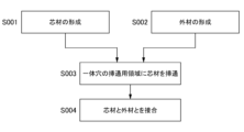
- FIG. 9 is a flow diagram of a manufacturing procedure for the blank 20 of this embodiment.
- the core material 21 is formed (S001) and the outer material 22 is formed (S002).
- the core material 21 specifically, powders of the materials for the core material 21 (here, tungsten carbide (WC) and cobalt (Co)) are mixed together and extrusion molded using a die (not shown).
- the core material 21 is formed into a shape as shown in FIG. 4B (a shape in which the outer shape of the cross section is approximately circular), and is then sintered.
- the outer material 22 specifically, in the same manner as in the formation of the core material 21, powders of the materials for the outer material 22 (here, tungsten carbide (WC) and cobalt (Co)) are mixed together and extrusion molded using a die 30 shown in FIG. 10, which will be described later. As a result, the outer material 22 is formed into a shape as shown in FIG. 4A (a shape in which the cross-sectional outline is approximately circular). Furthermore, an integral hole 27 having an insertion region 25 and an oil hole region 26 is formed in the outer material 22 by extrusion molding using the die 30.
- the materials for the outer material 22 here, tungsten carbide (WC) and cobalt (Co)
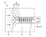
- FIG. 10 is an explanatory diagram of the die 30 for the external material 22 used in the manufacturing procedure for the blank 20 of this embodiment. As shown in FIG. 10, the die 30 has an extrusion section 31 and an integral hole pin 33.
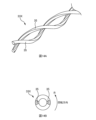
- FIG. 11 is an explanatory diagram of the integral hole pin 33 of the die 30. Note that FIG. 11A is an oblique view of the integral hole pin 33, and FIG. 11B is a view of the integral hole pin 33 from the tip side.
- the extrusion section 31 is a member through which the powder 36, which is the material of the outer material 22, passes.
- the extrusion section 31 is formed to have a substantially circular cross section, and by the powder 36 being extruded from the extrusion section 31 from the left side to the right side in FIG. 10, the outer shape of the cross section of the outer material 22 can be formed to be substantially circular.
- a groove forming portion 32 is formed on the inner surface of the extrusion portion 31.
- the groove forming portion 32 is a portion for forming the peripheral groove 23 and the marking portion 24 on the outer periphery 17 of the outer material 22 (blank 20).
- the groove of the groove forming portion 32 is formed as a spiral groove that has the same twist angle as the peripheral groove 23.
- the powder 36 is pushed from the left side to the right side in FIG. 10 while rotating in the extrusion section 31.
- This causes the outer material 22 to be extruded and also allows the outer circumferential groove 23 to be formed on the outer periphery 17 of the outer material 22 (blank 20).
- the groove forming section 32 is not formed in the area corresponding to the marking section 24, and this allows the marking section 24 to be formed.
- the pin 33 for integral hole is a member for forming the integral hole 27 in the external material 22 during extrusion molding of the external material 22.
- the pin 33 for integral hole is formed in a pin (rod) shape, and is arranged inside the extrusion section 31.
- the pin 33 for integral hole is also arranged along the extrusion direction of the powder 36 (i.e., the longitudinal direction of the blank 20). As a result, when the powder 36 is extruded while rotating through the extrusion section 31, the integral hole 27 is formed in the portion where the pin 33 for integral hole passes.
- the integrated hole pin 33 has an insertion pin 34 and an oil hole pin 35.
- the insertion pin 34 is a member for forming the insertion region 25.
- the oil hole pin 35 is a member for forming the oil hole region 26.
- the insertion pin 34 and the oil hole pin 35 are connected.
- “connected” may mean that the insertion pin 34 and the oil hole pin 35 are integrally formed, or that the insertion pin 34 and the oil hole pin 35 are separate and partially connected.
- the rigidity of the integral hole pin 33 can be maintained during extrusion, and the integral hole 27 can be formed with high precision in terms of shape and position.
- the insertion pin 34 is formed to extend parallel to the longitudinal direction of the drilling tool 10 to be manufactured (i.e., the longitudinal direction of the blank 20 to be manufactured).
- the oil hole pin 35 is formed to spirally wrap around the outer periphery of the insertion pin 34.
- the integrated hole 27 is formed along the rotation axis C, with the oil hole region 26 spirally wrapping around the insertion region 25.
- the outer material 22 extruded by the die 30 is sintered in a subsequent process.
- the outer material 22 is not completely sintered and is in a semi-sintered state.
- the core material 21 is inserted into the insertion region 25 as shown in Figs. 12A to 12C (S003 in Fig. 9). This defines the oil hole 14 between the outer periphery of the core material 21 inserted into the insertion region 25 and the edge of the oil hole region 26 of the outer material 22.
- FIG. 12 is a diagram showing how the core material 21 is inserted into the insertion region 25 of the integrated hole 27.
- FIG. 12A is a diagram showing the state before the core material 21 is inserted into the insertion region 25 of the integrated hole 27.
- FIG. 12B is a diagram showing the state in the middle of inserting the core material 21 into the insertion region 25 of the integrated hole 27.
- FIG. 12C is a diagram showing the state after the core material 21 has been inserted into the insertion region 25 of the integrated hole 27.
- the oil hole region 26 that communicates with the insertion region 25 opens toward the outer periphery 17, thereby expanding the insertion region 25. Therefore, even if the clearance between the core material 21 and the outer material 22 is small, it is possible to prevent high loads from being applied to the core material 21 or the outer material 22, and to prevent cracks from occurring, and in the subsequent process, it is possible to achieve optimal bonding between the core material 21 and the outer material 22.
- the outer material 22 is in a semi-sintered state after extrusion molding. Meanwhile, the core material 21 is completely sintered.
- the completely sintered core material 21 is inserted into the outer material 22, which is in a semi-sintered state.
- the core material 21 and the outer material 22 are further sintered as a whole, so that the outer material 22 is also completely sintered. This bonds the core material 21 and the outer material 22 together.
- components shrink when sintered, so when the core material 21 and the outer material 22 are sintered as a whole, both the core material 21 and the outer material 22 shrink.
- the outer material 22 is completely sintered from a semi-sintered state. For this reason, the outer material 22 shrinks more than the core material 21.
- the outer material 22 and the core material 21 have different degrees of shrinkage. In this process, the outer material 22 shrinks in a direction that tightens the core material 21 from the outside, so the core material 21 and the outer material 22 can be joined more firmly.
- the materials of the core material 21 and the outer material 22 of the blank 20 in this embodiment contain cobalt (Co). Therefore, the Co partially melts during sintering in this process, making it easier for the core material 21 and the outer material 22 to be joined together.
- Co cobalt
- the core material 21 may be in a semi-sintered state, and the core material 21 in a semi-sintered state may be inserted into the outer material 22 in a semi-sintered state, and the entire core material 21 and outer material 22 may be completely sintered in this step.
- the member when going from a semi-sintered state to completely sintered, the member will shrink more. For this reason, the accuracy of the shape and position of the oil hole 14 may be lower than in the present embodiment in which the core material 21 is completely sintered. Therefore, it is preferable that the completely sintered core material 21 is inserted into the outer material 22 in a semi-sintered state, and only the outer material 22 is completely sintered in this step, as in this embodiment.
- Fig. 13A is an explanatory diagram of a die 30X used in a manufacturing procedure of a blank 20X of a comparative example.
- Fig. 13B is a diagram of an example of a blank 20X formed by the die 30X, viewed from the tip side.
- Fig. 14 is an explanatory diagram of a hole pin 33X of the die 30X.
- Fig. 14A is a perspective view of the hole pin 33X
- Fig. 14B is a diagram of the hole pin 33X, viewed from the tip side.
- the two components, the core material 21 and the outer material 22, are formed separately, and then in a subsequent process, the core material 21 and the outer material 22 are joined to manufacture the blank 20.
- the oil hole 14 is formed directly in one component that corresponds to the core material 21 and the outer material 22.
- the mold 30X used in the manufacturing procedure of the blank 20X of the comparative example has an extrusion portion 31 and a hole pin 33X.
- the extrusion portion 31 is similar to the extrusion portion 31 of the mold 30 in this embodiment.
- the hole pin 33X does not have an insertion pin 34, and only has an oil hole pin 35.
- the oil hole pin 35 is very thin and is not connected to the insertion pin 34, so it has low rigidity. For this reason, as shown in FIG. 13A, when the powder 36 passes through the hole pin 33, it may cause the oil hole pin 35 to shift in position. This may cause the oil hole 14 to shift in position in the extrusion-molded blank 20X, as shown in FIG. 13B.
- the oil hole pin 35 which has low rigidity, is more likely to shift in position. Therefore, in the manufacturing procedure for the blank 20X of the comparative example, it is difficult to form the opening of the oil hole 14 with high precision in terms of shape and position.
- the integral hole 27 can be formed with high precision in terms of shape and position.
- the opening of the oil hole 14 can be formed with high precision in terms of shape and position.
- a drilling tool 10 having the following features.
- Aspect 1 comprises a core material 21 and an outer material 22 positioned around the core material 21.
- the outer material 22 has an integral hole 27 formed therein, the integral hole 27 having an insertion region 25 through which the core material 21 is inserted and an oil hole region 26 communicating with the insertion region 25.
- An oil hole 14 is defined by the outer periphery of the core material 21 inserted into the insertion region 25 and the edge of the oil hole region 26 of the outer material 22.
- the above-mentioned aspect allows the opening of the oil hole 14 to be positioned precisely at a predetermined position, and prevents the oil hole 14 from bending or undulating on the way to the opening.
- the core material 21 and the outer material 22 are made of different materials.
- the above-mentioned aspect improves the freedom of selection of the material used for the drilling tool 10.
- the oil hole 14 is formed in a spiral shape along the longitudinal direction.
- the oil hole 14 can be formed along the shape of the discharge groove 11, which is formed in a spiral shape.
- the oil hole 14 has a tapered portion 15 whose width narrows from the outer periphery 17 side toward the center 18 side when viewed in the longitudinal direction from the tip DE side.
- the oil holes 14 when viewed in the longitudinal direction from the tip DE side of the drilling tool 10, can be efficiently positioned in correspondence with the discharge grooves 11 and cutting edges 12 being radially positioned from the center 18.
- the oil hole 14 is located closer to the center 18 than the tapered portion 15 when viewed in the longitudinal direction from the tip DE side, and has a widened portion 16 that becomes wider as it approaches the center 18 side.
- the amount and pressure of cutting oil can be increased even in the area of the center 18 where the width of the oil hole 14 is narrower.
- a plurality of oil holes 14 are formed, and the plurality of oil holes 14 are positioned so as to be rotationally symmetrical about the center 18 when viewed in the longitudinal direction from the tip DE side.
- the above-mentioned aspect allows cutting oil to be supplied uniformly to the machining surface.
- the above-mentioned aspect allows the amount of cutting oil supplied to the machining surface to be increased.
- a blank 20 for a drilling tool 10 having the following configuration:
- Aspect 8 comprises a core material 21 and an outer material 22 positioned around the core material 21, and the outer material 22 has an integral hole 27 formed therein, when viewed longitudinally from the tip DE side, which has an insertion region 25 through which the core material 21 is inserted and an oil hole region 26 communicating with the insertion region 25, and the oil hole 14 is defined by the outer periphery of the core material 21 inserted into the insertion region 25 and the edge of the oil hole region 26 of the outer material 22.
- the above-mentioned aspect allows the opening of the oil hole 14 to be positioned precisely at a predetermined position, and prevents the oil hole 14 from bending or undulating on the way to the opening.
- a method for manufacturing a blank 20 for a drilling tool 10 is provided as follows:
- Aspect 9 includes the steps of forming a core material 21, forming an outer material 22 in which an integrated hole 27 is formed, the integrated hole 27 having an insertion region 25 through which the core material 21 is inserted and an oil hole region 26 communicating with the insertion region 25 when viewed in the longitudinal direction from the tip DE side, and inserting the core material 21 into the insertion region 25, and defining the oil hole 14 by the outer periphery of the core material 21 inserted into the insertion region 25 and the edge of the oil hole region 26 of the outer material 22.
- the above-mentioned aspect allows the opening of the oil hole 14 to be positioned precisely at a predetermined position, and prevents the oil hole from bending or undulating on its way to the opening.
- the outer material 22 is formed by extrusion molding using a mold 30, and the mold 30 has an insertion pin 34 for forming the insertion region 25 and an oil hole pin 35 for forming the oil hole region 26, and the insertion pin 34 and the oil hole pin 35 are connected.
- the above-mentioned embodiment can improve the rigidity of the oil hole pin 35.
- the insertion pin 34 is formed so as to extend parallel to the longitudinal direction of the drilling tool 10, and the oil hole pin 35 is formed so as to wrap around the outer periphery of the insertion pin 34 in a spiral shape.
- the oil hole 14 of the drilling tool 10 can be formed in a spiral shape along the longitudinal direction.
Landscapes
- Engineering & Computer Science (AREA)
- Mechanical Engineering (AREA)
- Drilling Tools (AREA)
Priority Applications (4)
| Application Number | Priority Date | Filing Date | Title |
|---|---|---|---|
| JP2024559803A JPWO2024111092A1 (https=) | 2022-11-24 | 2022-11-24 | |
| EP22966502.1A EP4603218A4 (en) | 2022-11-24 | 2022-11-24 | DRILLING TOOL, DRILLING TOOL RAW, AND METHOD FOR MANUFACTURING DRILLING TOOL RAW |
| CN202280102075.3A CN120265408A (zh) | 2022-11-24 | 2022-11-24 | 开孔工具、开孔工具用的坯料、及开孔工具用的坯料的制造方法 |
| PCT/JP2022/043396 WO2024111092A1 (ja) | 2022-11-24 | 2022-11-24 | 穴あけ工具、穴あけ工具用のブランク及び穴あけ工具用のブランクの製造方法 |
Applications Claiming Priority (1)
| Application Number | Priority Date | Filing Date | Title |
|---|---|---|---|
| PCT/JP2022/043396 WO2024111092A1 (ja) | 2022-11-24 | 2022-11-24 | 穴あけ工具、穴あけ工具用のブランク及び穴あけ工具用のブランクの製造方法 |
Publications (1)
| Publication Number | Publication Date |
|---|---|
| WO2024111092A1 true WO2024111092A1 (ja) | 2024-05-30 |
Family
ID=91196018
Family Applications (1)
| Application Number | Title | Priority Date | Filing Date |
|---|---|---|---|
| PCT/JP2022/043396 Ceased WO2024111092A1 (ja) | 2022-11-24 | 2022-11-24 | 穴あけ工具、穴あけ工具用のブランク及び穴あけ工具用のブランクの製造方法 |
Country Status (4)
| Country | Link |
|---|---|
| EP (1) | EP4603218A4 (https=) |
| JP (1) | JPWO2024111092A1 (https=) |
| CN (1) | CN120265408A (https=) |
| WO (1) | WO2024111092A1 (https=) |
Citations (4)
| Publication number | Priority date | Publication date | Assignee | Title |
|---|---|---|---|---|
| JP2005262348A (ja) * | 2004-03-17 | 2005-09-29 | Nippon Seratekku Kk | 回転刃物体および回転刃物体による孔あけ方法 |
| JP2010064171A (ja) * | 2008-09-09 | 2010-03-25 | Osg Corp | 流体供給穴付き加工工具 |
| JP2011020254A (ja) | 2009-06-15 | 2011-02-03 | Mitsubishi Materials Corp | クーラント穴付きドリル |
| JP2020104253A (ja) | 2018-12-26 | 2020-07-09 | 三菱マテリアル株式会社 | クーラント穴付き回転工具 |
Family Cites Families (4)
| Publication number | Priority date | Publication date | Assignee | Title |
|---|---|---|---|---|
| DE3601385A1 (de) * | 1986-01-18 | 1987-07-23 | Krupp Gmbh | Verfahren zur herstellung von sinterkoerpern mit inneren kanaelen, strangpresswerkzeug zur durchfuehrung des verfahrens und bohrwerkzeug |
| DE102009043850A1 (de) * | 2009-08-25 | 2011-03-03 | Arno Friedrichs | Werkzeug |
| WO2014118881A1 (ja) * | 2013-01-29 | 2014-08-07 | オーエスジー株式会社 | ドリル |
| CN116209534B (zh) * | 2020-08-21 | 2025-09-23 | 京瓷株式会社 | 切削刀片、旋转刀具以及切削加工物的制造方法 |
-
2022
- 2022-11-24 EP EP22966502.1A patent/EP4603218A4/en active Pending
- 2022-11-24 WO PCT/JP2022/043396 patent/WO2024111092A1/ja not_active Ceased
- 2022-11-24 JP JP2024559803A patent/JPWO2024111092A1/ja active Pending
- 2022-11-24 CN CN202280102075.3A patent/CN120265408A/zh active Pending
Patent Citations (4)
| Publication number | Priority date | Publication date | Assignee | Title |
|---|---|---|---|---|
| JP2005262348A (ja) * | 2004-03-17 | 2005-09-29 | Nippon Seratekku Kk | 回転刃物体および回転刃物体による孔あけ方法 |
| JP2010064171A (ja) * | 2008-09-09 | 2010-03-25 | Osg Corp | 流体供給穴付き加工工具 |
| JP2011020254A (ja) | 2009-06-15 | 2011-02-03 | Mitsubishi Materials Corp | クーラント穴付きドリル |
| JP2020104253A (ja) | 2018-12-26 | 2020-07-09 | 三菱マテリアル株式会社 | クーラント穴付き回転工具 |
Non-Patent Citations (1)
| Title |
|---|
| See also references of EP4603218A4 |
Also Published As
| Publication number | Publication date |
|---|---|
| CN120265408A (zh) | 2025-07-04 |
| EP4603218A4 (en) | 2026-01-14 |
| EP4603218A1 (en) | 2025-08-20 |
| JPWO2024111092A1 (https=) | 2024-05-30 |
Similar Documents
| Publication | Publication Date | Title |
|---|---|---|
| CN111683776B (zh) | 模块化切削刀具本体及其制造方法 | |
| US7762748B2 (en) | Drill | |
| JP4704495B2 (ja) | タービン翼接続用溝の切削加工方法およびそれに用いるクリスマスカッタ | |
| US9636756B2 (en) | Multi-lip drilling tool with internal cooling ducts | |
| KR101514101B1 (ko) | 공작 기계용 드릴링 공구 및 이의 제조 방법 | |
| US20050105981A1 (en) | Hole cutter and method for producing | |
| EP3375562B1 (en) | Method of producing a blank for a shaft milling tool and such a blank | |
| KR20100111626A (ko) | 솔리드 스텝 드릴 | |
| WO2009142323A1 (ja) | ドリルおよび切削インサート並びに被削加工物の製造方法 | |
| JP2003275928A (ja) | 工具及びその製造方法 | |
| US20120087753A1 (en) | Drill and cutting method using same | |
| JP5087735B2 (ja) | ドリル | |
| US20240375190A1 (en) | Step drill bit and method for drilling a workpiece by using a step drill bit | |
| WO2024111092A1 (ja) | 穴あけ工具、穴あけ工具用のブランク及び穴あけ工具用のブランクの製造方法 | |
| EP2902142B1 (en) | Drill and method for manufacturing cut workpieces using same | |
| JP5845288B2 (ja) | ドリルおよびそれを用いた切削加工物の製造方法 | |
| US9969012B2 (en) | Drill and method for manufacturing cut product using same | |
| JP2003275915A (ja) | 超硬合金製油穴付きドリルの製造方法および超硬合金製油穴付きドリル | |
| JP2003277807A (ja) | 超硬合金製油穴付きドリルの製造方法および超硬合金製油穴付きドリル | |
| KR102425210B1 (ko) | 테이퍼 드릴 리머의 제조 방법 및 이에 의해 제조된 테이퍼 드릴 리머 | |
| JP2000033510A (ja) | 穴明け工具 | |
| CN210789376U (zh) | 一种快速倒角钻头及钻床组件 | |
| KR20250094672A (ko) | 로터리 금속 절삭 공구를 위한 블랭크 | |
| JP2011125941A (ja) | ドリル |
Legal Events
| Date | Code | Title | Description |
|---|---|---|---|
| 121 | Ep: the epo has been informed by wipo that ep was designated in this application |
Ref document number: 22966502 Country of ref document: EP Kind code of ref document: A1 |
|
| WWE | Wipo information: entry into national phase |
Ref document number: 2024559803 Country of ref document: JP |
|
| WWE | Wipo information: entry into national phase |
Ref document number: 2022966502 Country of ref document: EP |
|
| WWE | Wipo information: entry into national phase |
Ref document number: CN2022801020753 Country of ref document: CN Ref document number: 202280102075.3 Country of ref document: CN |
|
| ENP | Entry into the national phase |
Ref document number: 2022966502 Country of ref document: EP Effective date: 20250514 |
|
| NENP | Non-entry into the national phase |
Ref country code: DE |
|
| WWP | Wipo information: published in national office |
Ref document number: 202280102075.3 Country of ref document: CN |
|
| WWP | Wipo information: published in national office |
Ref document number: 2022966502 Country of ref document: EP |