WO2024101150A1 - イオン選択性電極、および電解質濃度測定装置 - Google Patents
イオン選択性電極、および電解質濃度測定装置 Download PDFInfo
- Publication number
- WO2024101150A1 WO2024101150A1 PCT/JP2023/038452 JP2023038452W WO2024101150A1 WO 2024101150 A1 WO2024101150 A1 WO 2024101150A1 JP 2023038452 W JP2023038452 W JP 2023038452W WO 2024101150 A1 WO2024101150 A1 WO 2024101150A1
- Authority
- WO
- WIPO (PCT)
- Prior art keywords
- ion
- electrode
- selective electrode
- membrane
- solution
- Prior art date
- Legal status (The legal status is an assumption and is not a legal conclusion. Google has not performed a legal analysis and makes no representation as to the accuracy of the status listed.)
- Ceased
Links
Images







Classifications
-
- G—PHYSICS
- G01—MEASURING; TESTING
- G01N—INVESTIGATING OR ANALYSING MATERIALS BY DETERMINING THEIR CHEMICAL OR PHYSICAL PROPERTIES
- G01N27/00—Investigating or analysing materials by the use of electric, electrochemical, or magnetic means
- G01N27/26—Investigating or analysing materials by the use of electric, electrochemical, or magnetic means by investigating electrochemical variables; by using electrolysis or electrophoresis
- G01N27/28—Electrolytic cell components
- G01N27/30—Electrodes, e.g. test electrodes; Half-cells
- G01N27/333—Ion-selective electrodes or membranes
Definitions
- This disclosure relates to an ion-selective electrode and an electrolyte concentration measuring device equipped with the same.
- the potentiometric method using an ion selective electrode is used in a wide range of fields, including water quality analysis and medicine, because it can quickly and easily quantify the concentration of specific ions in a liquid.
- ISE ion selective electrode
- the medical field there is a close relationship between metabolic reactions in the body and ion concentration, and quantifying specific ions contained in biological samples such as serum and urine is used to diagnose hypertension, kidney disease, and neurological disorders. Since clinical testing requires the continuous analysis of a large number of samples, high-throughput automatic analyzers and electrolyte concentration measuring devices equipped with ion selective electrodes are used on a daily basis.
- the main measurement items for electrolyte concentration measuring devices are cations such as sodium ions and potassium ions, and anions such as chloride ions.
- cations such as sodium ions and potassium ions
- anions such as chloride ions.
- compounds (ionophores) that selectively capture specific cations such as crown ethers and valinomycin, have been discovered.
- Membranes containing these ionophores are generally used as the ion-sensitive membranes of cation-selective electrodes for sodium, potassium, etc., and have high ion selectivity.
- Patent Document 1 discloses a chloride ion-sensitive membrane based on an anion exchange membrane, the surface of which is coated with a condensate of metaphenylenediamine and formaldehyde.
- Patent Document 2 discloses an anion-selective electrode in which the surface of the anion exchange membrane that comes into contact with the sample liquid is coated with an epoxyamine resin that is responsive to anions.
- a sample contains many types of ions other than the ions to be measured, and these types of ions interfere with the measurement of the concentration of the ions to be measured.
- blood serum a sample
- HCO 3 - bicarbonate ions
- chloride ion selective electrode it is important for a chloride ion selective electrode to have low selectivity for bicarbonate ions.
- an ion-sensitive membrane containing the above-mentioned ionophore it is common to use an ion-sensitive membrane containing the above-mentioned ionophore, but an ion-sensitive membrane that does not contain an ionophore can also be used in an ion-selective electrode.
- the present disclosure provides a technology for improving the ion selectivity and stability over time in a simpler manner for an ion-selective electrode based on an ion exchange membrane with a high density of fixed charges.
- an ion-selective electrode for measuring target ions contained in a sample liquid comprising an electrode housing that contains an internal liquid, an internal electrode that is partially in contact with the internal liquid, and an ion-sensitive membrane that separates the sample liquid from the internal liquid, wherein at least a portion of a first surface of the ion-sensitive membrane is in contact with the sample liquid and at least a portion of a second surface that is different from the first surface is in contact with the internal liquid, and the first surface of the ion-sensitive membrane is coated with an inactive layer that suppresses an ion exchange reaction between the ion-sensitive membrane and the sample liquid.
- the technology disclosed herein makes it possible to improve the ion selectivity and stability over time in an ion-selective electrode based on an ion exchange membrane with a high density of fixed charges in a simpler manner.
- FIG. 1 is a front view of a flow-type ion selective electrode 10.
- FIG. 2 is a diagram showing an example of the configuration of a flow-type ion selective electrode 10 in the A-A' cross section of FIG. 1A.
- FIG. 1D is a schematic enlarged view of the dotted rectangle 17-1 portion of FIG. 1C, showing the characteristic layer structure of the ion-sensitive film 17 according to this embodiment.
- 1 is a diagram showing an example of the configuration of an electrolyte concentration measuring device (flow type) 100 including an ion selective electrode according to the present disclosure.
- FIG. 4 is a flowchart for explaining an operation at the start-up of the electrolyte concentration measuring device 100. 4 is a flowchart for explaining the operation of the electrolyte concentration measuring device 100 during continuous analysis.
- FIG. 1D is a schematic enlarged view of a dotted rectangle 17-1 in FIG. 1C, showing the layer structure of the ion-sensitive film 17 that is characteristic of this embodiment. 1C ⁇ , ⁇ 2 ⁇ 1 ⁇
- FIG 2 is an enlarged view of the dotted rectangle 17-1 in FIG. 1C, showing the layer structure of the ion-sensitive membrane of Comparative Example 1.
- FIG. 1D is an enlarged view of the dotted rectangle 17-1 in FIG. 1C, showing the layer structure of the ion-sensitive membrane of Comparative Example 2.
- FIG. 1D is a schematic enlarged view of a dotted rectangle 17-1 in FIG. 1C, showing the layer structure of the ion-sensitive membrane of Comparative Example 2.
- FIG. 1D is a schematic enlarged view of a dotted rectangle
- FIG. 13 is a diagram showing an example of a cross-sectional configuration of a stick-type ion selective electrode 20 according to a third embodiment.
- FIG. 1 is a diagram showing a comparison result of the response behavior of an ion-selective electrode 10 having the structure shown in the first embodiment, in which PVC is used as the material for the inactive layer 5, and an electrode of Comparative Example 1, to aqueous solutions containing ions of various concentrations and types.
- FIG. 2 is a diagram showing a schematic diagram of the ion-sensitive membrane and the ion composition inside the sample solution of Comparative Example 1.
- FIG. 1 is a diagram showing a schematic diagram of the ion composition inside an ion-sensitive membrane 17 and a sample solution in the case of an ion-selective electrode 10 having an inactive layer 5.
- FIG. FIG. 10 shows the results of calculating the slope and each interfering ion selectivity coefficient for chloride ion (Cl ⁇ ) from the potential value at a relatively stable timing after the second introduction of each sample solution.
- FIG. 11 is a diagram showing the measurement results of the selectivity coefficient of bicarbonate ion (HCO 3 ⁇ ) relative to chloride ion (Cl ⁇ ) for the ion selective electrode having the structure according to Comparative Example 1 (see FIG.
- FIG. 11 is a diagram showing the measurement results of the selectivity coefficient of bicarbonate ion (HCO 3 ⁇ ) relative to chloride ion (Cl ⁇ ) for the ion selective electrode having the structure according to Comparative Example 2 (see FIG. 8) and the ion selective electrode having the structure according to the second embodiment (see FIG. 6).
- the present embodiment relates to an ion-selective electrode for measuring the ion concentration in a liquid, and an electrolyte concentration measuring device including the same.
- the ion-sensitive membrane that constitutes the ion-selective electrode in each embodiment includes an ion-exchange membrane with a high charge density, and an inactive layer (a layer made of a material that does not respond to ions) formed on the surface of the ion-exchange membrane that comes into contact with the sample containing the ions to be measured.
- the first embodiment discloses a flow-type ion selective electrode 10.
- the embodiment will be described using a chloride ion selective electrode as an example, but the technology of the present disclosure is also applicable to ion selective electrodes for measuring the concentrations of other types of ions (e.g., Br ⁇ , I ⁇ , CN ⁇ , Cd 2+ , Cu 2+ , Ag + , S 2 ⁇ , F ⁇ , K + , Ca 2+ , NO 3 ⁇ , NH 4 + , Na + , etc.).
- other types of ions e.g., Br ⁇ , I ⁇ , CN ⁇ , Cd 2+ , Cu 2+ , Ag + , S 2 ⁇ , F ⁇ , K + , Ca 2+ , NO 3 ⁇ , NH 4 + , Na + , etc.
- FIGS. 1A to 1C are diagrams showing an example of the overall configuration of a flow-type ion selective electrode 10 according to a first embodiment.
- Fig. 1A is a front view of the flow-type ion selective electrode 10.
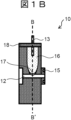
- Fig. 1B is a diagram showing an example of the configuration of the flow-type ion selective electrode 10 in the AA' cross section of Fig. 1A.
- Fig. 1C is a diagram showing an example of the configuration of the flow-type ion selective electrode 10 in the BB' cross section perpendicular to the AA' cross section.
- the flow-type ion-selective electrode 10 has an electrode housing 11, an internal electrode 13, a flow path 12 that passes through the electrode housing 11, a gasket 15, an internal gel container that contains an internal gel 16, an ion-sensitive membrane 17, and a lid 18.
- the sample liquid to be measured passes through (flows through) the flow path 12.
- the ion-sensitive membrane 17 is installed so that it can come into contact with the sample liquid.
- the internal gel (or internal liquid) 16 contains an electrolyte and is contained in the internal gel container in the electrode housing 11 so as to fill it.
- the internal electrode 13 is also installed so that it can come into contact with the internal gel 16.
- the lid 18 is attached to the opening of the electrode housing 11 to confine the internal gel 16 in the electrode housing.
- the packing 15 is also provided near the entrance and exit of the flow path 12 of the electrode housing 11 so that it can be connected to an electrolyte concentration measuring device (electrolyte concentration analyzing device) described below or the flow path of another electrode.
- the ion-selective electrode 10 having the above configuration is mounted on an electrolyte concentration measuring device.
- the internal electrode 13 is connected to the wiring on the device side, so that the potential generated according to the concentration of the ions to be measured contained in the sample liquid can be measured, and the concentration of the ions to be measured can be analyzed.
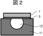
- FIG. 2 is an enlarged schematic diagram of the dotted rectangle 17-1 in FIG. 1C, and shows the characteristic layer structure of the ion-sensitive film 17 according to this embodiment.
- the ion-sensitive membrane 17 is based on an anion exchange membrane 1 having a high density of immobilized cations (it is an anion exchange membrane in order to measure anions, and a cation exchange membrane in order to measure cations).
- the anion exchange membrane 1 has chloride ions ( Cl- ) as counter ions.
- THF tetrahydrofuran
- the THF is then evaporated to form a thin layer of polymer on the surface of the ion-sensitive membrane 17. This layer is called the inactive layer 5.
- the method for forming the inactive layer 5 described here is one example, and other methods may be used.
- the anion exchange membrane 1 is adhered to the electrode housing 11 so as to cover the opening provided in the electrode housing 11.
- the anion exchange membrane 1 constituting the ion-sensitive membrane 17 can be a highly cross-linked polystyrene-based membrane having quaternary ammonium ions as anion exchange groups, and reinforced with woven PVC (polyvinyl chloride) yarn fabric.
- the ion exchange group may be a primary to tertiary amino group
- the base material may not be a styrene-based material but may be other hydrocarbon-based resins such as polyolefins or fluorine-based resins.
- the reinforcing material may also be other materials such as other polymer fibers or glass fibers, and the membrane may not have a reinforcing material.
- the counter ions contained in the anion exchange membrane 1 are preferably the same type of ions as the ions to be measured, but may be other anions. Furthermore, the effects of the technology disclosed herein can be achieved with any membrane that has a high density of fixed charges, even if it is not made of a material used in general ion exchange membranes.
- high density means that the charge density is about 0.1 to 10 mmol/g.
- liquid membrane type membrane there is a type of ion-sensitive membrane different from the ion-sensitive membrane 17 of the present disclosure, known as a liquid membrane type membrane. This is generally achieved by dissolving a lipophilic salt as a fixed charge in a membrane such as soft PVC, and incorporating an ionophore that improves ion selectivity. In such liquid membrane type ion-sensitive membranes, the charge density is approximately 0.001 to 0.1 mmol/g.
- the inactive layer 5 has a function of suppressing the ion exchange reaction between the ion exchange membrane 1 and the sample liquid.
- the inactive layer 5 is characterized by having a charge density of, for example, 0.0001 mmol/g or less and being non-ion responsive (made of a material that is non-ion responsive).
- the material of the inactive layer 5 is preferably an insulating material such as a general polymer, which is non-water soluble so as not to dissolve in the sample liquid.
- the inactive layer 5 is formed by a method such as that of this embodiment (when the inactive layer 5 is formed by applying a solution in which a polymer is dissolved in tetrahydrofuran (THF) as described above), it is preferable to use a material that is easily soluble in a solvent with a low boiling point.
- THF tetrahydrofuran
- Materials that can be used for the inactive layer 5 include, for example, Poly(vinyl chloride) (PVC), Ethylene/vinyl acetate copolymer, Poly(vinyl formal), and mixed materials of polymer and plasticizer Dioctyl adipate (DOA), such as PVC+DOA, Ethylene/vinyl acetate copolymer+DOA, Poly(ethyl methacrylate)+DOA, and Poly(vinyl acetate)+DOA. Specific electrode performance will be described later. All of these are materials that exhibit the effects of the technology disclosed herein, but the type of polymer material and plasticizer is not limited to these. Any inactive material that does not respond to ions and suppresses the ion exchange reaction between the ion exchange membrane 1 and the sample liquid can be used.
- PVC Poly(vinyl chloride)
- DOA Dioctyl adipate
- PVC+DOA Ethylene/vinyl acetate copoly
- the material of the inactive layer 5 can be a polymer containing carbon and hydrogen as elements. Furthermore, in order to improve adhesion to the ion exchange membrane 1, elements such as chlorine and oxygen can be included. However, the material is not limited to this, and any material that satisfies the above conditions (having the function of suppressing ion exchange reactions; having a charge density of 0.0001 mmol/g or less; not responding to ions) can be used. Furthermore, in addition to polymer materials, low molecular weight materials and inorganic materials can be used, and composite materials in which multiple materials are mixed can also be used. Furthermore, the inactive layer 5 can be made up of multiple layers.
- the inactive layer 5 is made of an insulating material as described above, but must be formed to be appropriately thin in order to create a state in which ion transmission is not completely insulated. Specifically, if ion exchange is completely blocked, there will be no ion response, so a layer thickness of 10 ⁇ m or less is required. On the other hand, a layer thickness of 0.10 ⁇ m or more is required to obtain the effect of suppressing the ion exchange reaction.
- the ion-selective electrode 10 has an inactive layer 5 on the surface of the ion exchange membrane 1, so that the ion exchange reaction between the ion exchange membrane 1 and the sample liquid can be suppressed, and the electrode characteristics during practical use can be made closer to the original ion selectivity characteristics of the ion-sensitive membrane 17.
- the epoxyamine resin itself responds to ions, so the response characteristics of the epoxyamine resin itself become the electrode characteristics. If the response characteristics of the epoxyamine resin deteriorate over time, the electrode characteristics will also deteriorate.
- the epoxyamine resin itself is required to have response characteristics that are stable over time.
- the inactive layer 5 does not originally have ion response, so the characteristics are less likely to deteriorate.
- the inactive layer 5 only needs to have the function of suppressing the ion exchange reaction between the ion exchange membrane 1 and the sample liquid. Therefore, as long as the above-mentioned certain conditions (having the ability to suppress ion exchange reactions; having a charge density of 0.0001 mmol/g or less; not responding to ions) are met, the material for the inactive layer 5 can be selected from a wide range of materials. Furthermore, it is also possible to select a material that does not easily cause components contained in the measurement sample to adhere to the membrane surface.
- a chloride ion selective electrode has been described, but this technology can also be applied to other anion selective electrodes and cation selective electrodes.
- an ion exchange membrane 1 that corresponds to the ion to be measured.
- a cation selective electrode requires the use of an ion exchange membrane that has a fixed charge opposite to that of an anion selective electrode (e.g., sulfonic acid or carboxylic acid group: ions in the ion exchange membrane are fixed with negative ions, and positive ions (as an example, the ions to be measured) serve as counter ions).
- an anion selective electrode e.g., sulfonic acid or carboxylic acid group: ions in the ion exchange membrane are fixed with negative ions, and positive ions (as an example, the ions to be measured) serve as counter ions).
- ⁇ Configuration example of electrolyte concentration measuring device> 3 is a diagram showing a configuration example of an electrolyte concentration measuring device (flow type) 100 equipped with an ion selective electrode according to the present disclosure.
- the electrolyte concentration measuring device 100 is a device for analyzing the concentrations of three types of ions, for example, Na, K, and Cl ions.
- the electrolyte concentration measuring device 100 includes a measuring unit 170, a potential measuring unit 171, a concentration calculating unit 172, an output unit 174, a device control unit 175, and an input unit 176.
- the measurement unit 170 is equipped with three types of electrodes, ie, a chloride (Cl) ion electrode 101, a potassium (K) ion electrode 102, and a sodium (Na) ion electrode 103, which are ion selective electrodes, and a comparison electrode 104.
- the dilution tank 110 of the measurement unit 170 is a cup for temporarily storing a sample diluted by mixing a sample dispensed from a sample nozzle (not shown) with a dilution solution dispensed from a dilution solution supply nozzle 108, or an internal standard solution dispensed from an internal standard solution supply nozzle 109.
- the sipper nozzle 107 When the sipper nozzle 107 is lowered into the dilution tank 110 under the control of the device control unit 175, it introduces the diluted sample or internal standard solution in the dilution tank 110 into the flow path of the ion selective electrodes 101 to 103.
- the comparison electrode solution is introduced from the comparison electrode solution bottle 161 into the flow path of the comparison electrode 104 using the sipper syringe pump 133.
- the vacuum suction nozzle 106 descends under the control of the device control unit 175, aspirating the diluted sample or internal standard remaining in the dilution tank 110 and discharging it into the waste tank 111.
- the device control unit 175 opens the solenoid valve 121, closes the pinch valve 105, and pulls the sipper syringe pump 133. This introduces the reference electrode solution from the reference electrode solution bottle 161 into the flow path of the reference electrode 104.
- the device control unit 175 also closes the solenoid valve 122, opens the solenoid valve 125, and pushes the sipper syringe pump 133 to discharge the solution accumulated in the sipper syringe pump 133.
- the reference electrode liquid introduced into the flow path of the reference electrode 104 and the liquid introduced into each of the ion selective electrodes 101 to 103 come into contact at the liquid junction 120.
- each of the ion selective electrodes 101 to 103 and the reference electrode 104 are electrically connected through the liquid.
- the electromotive force (electric potential) between the reference electrode 104 and each of the ion selective electrodes 101 to 103 changes depending on the concentration of the ion to be measured in the liquid introduced into the flow path of the ion selective electrodes 101 to 103, etc.
- This potential information is acquired by the potential measurement unit 171.
- the concentration calculation unit 172 receives the potential measured at a stable timing suitable for concentration calculation from the potential measurement unit 171, and calculates the concentration of the ion to be measured.
- the output unit 174 displays the operating status of the device received from the device control unit 175 and the calculation results from the concentration calculation unit 172.
- the operator can input sample information, various parameters, device operation commands, etc. from the input unit 176. The calculation method will be described in detail later.
- FIG. 4 is a flow chart for explaining the operation of electrolyte concentration measuring device 100 at start-up.
- the operator starts up the electrolyte concentration measuring device 100 by, for example, turning on the power switch (S201).
- the operator installs (mounts) the ion selective electrodes 101 to 103 in the device 100 (S202), and further installs a reagent bottle in the device 100 (S203).
- the device control unit 175 performs reagent priming (replacing and filling each syringe pump and flow path with new reagent) (S204).
- the device control unit 175 performs continuous measurement of the internal standard solution to confirm that the potential of the electrode is stable (S205).
- the device control unit 175 measures two types of standard solutions of known concentrations and calculates the slope in order to obtain a calibration curve of the ion selective electrodes 101 to 103 (S206). Next, the device control unit 175 calculates the internal standard solution concentration (S207).
- the device control unit 175 introduces the reference electrode solution from the reference electrode solution bottle 161 into the flow path of the reference electrode 104. At this time, the reference electrode solution and the diluted known low-concentration standard solution come into contact with each other at the liquid junction 120.
- the device control unit 175 uses the potential measurement unit 171 to measure the electromotive forces between the ion selective electrodes 101 to 103 and the comparison electrode 104 while the liquid is stationary after the diluted standard solution is introduced into the electrode flow path. Meanwhile, the device control unit 175 controls the vacuum suction nozzle 106 to suck up the remaining liquid in the dilution tank 110, and then dispenses the internal standard solution in the internal standard solution bottle 141 into the dilution tank 110.
- the device control unit 175 sucks the internal standard solution in the dilution tank 110 from the sipper nozzle 107, fills the flow paths of the ion selective electrodes 101 to 103 with the internal standard solution, and introduces the comparison electrode solution from the comparison electrode solution bottle 161 into the flow path of the comparison electrode 104. After that, the device control unit 175 controls the potential measurement unit 171 to measure the electromotive forces of each electrode while the liquid is stationary after the internal standard solution is introduced into the electrode flow path.
- the device control unit 175 sucks up the remaining liquid in the dilution tank 110 with the vacuum suction nozzle 106, and then dispenses the known high-concentration standard liquid into the dilution tank 110 with a dispensing nozzle (not shown). After that, the device control unit 175 uses the dilution syringe pump 132 to dispense the dilution liquid in the dilution liquid bottle 151 into the dilution tank 110, diluting the known high-concentration standard liquid at the set ratio D.
- the device control unit 175 sucks the diluted known high concentration standard solution in the dilution tank 110 through the sipper nozzle 107 and introduces it into the flow path of the ion selective electrodes 101 to 103.
- the device control unit 175 then introduces the reference electrode solution from the reference electrode solution bottle 161 into the flow path of the reference electrode 104.
- the reference electrode solution and the diluted known high concentration standard solution come into contact at the liquid junction 120.
- the device control unit 175 controls the potential measurement unit 171 to measure the electromotive forces between the ion selective electrodes 101 to 103 and the reference electrode 104 while the solution is stationary after the diluted standard solution is introduced into the electrode flow path. Meanwhile, the device control unit 175 sucks up the remaining liquid in the dilution tank with a vacuum suction nozzle, and then dispenses the internal standard solution in the internal standard solution bottle 141 into the dilution tank.
- the device control unit 175 sucks the internal standard solution from the dilution tank 110 through the sipper nozzle 107, fills the flow paths of the ion selective electrodes 101 to 103 with the internal standard solution, and introduces the reference electrode solution from the reference electrode solution bottle 161 into the flow path of the reference electrode 104.
- the device control unit 175 then controls the potential measurement unit 171 to measure the electromotive force of each electrode after the internal standard solution is introduced into the electrode flow path while the liquid is stationary.
- the device control unit 175 also sucks up the remaining liquid in the dilution tank 110 with a vacuum suction nozzle.
- the electromotive forces of the three types of liquids, the low-concentration standard liquid, the high-concentration standard liquid, and the internal standard liquid are obtained by the potential measurement unit 171.
- the device control unit 175 controls the concentration calculation unit 172, and calculates the slope sensitivity SL, which corresponds to the calibration curve, from the electromotive force (EMF) received from the potential measurement unit 171 using the following formula.
- the above operation is called calibration.
- the slope sensitivity SL corresponds to 2.303 ⁇ (RT/zF) in the Nernst equation (2) below.
- the electrolyte concentration measuring device 100 obtains the slope sensitivity SL specific to the electrode by the above calibration.
- E E0 + 2.303 x (RT / zF) x log (f x C) ....
- E0 is a constant potential determined by the measurement system
- z is the valence of the ion to be measured
- F is the Faraday constant
- R is the gas constant
- T the absolute temperature
- f the activity coefficient
- C is the ion concentration.
- Fig. 5 is a flow chart for explaining the operation of electrolyte concentration measuring device 100 during continuous analysis.
- the device control unit 175 When the device control unit 175 starts the measurement operation (S301), it dispenses the internal standard solution in the internal standard solution bottle 141 into the dilution tank 110. Next, the device control unit 175 sucks the internal standard solution in the dilution tank 110 from the sipper nozzle 107, fills the flow paths of the ion selective electrodes 101 to 103 with the internal standard solution, and introduces the reference electrode solution from the reference electrode solution bottle 161 into the flow path of the reference electrode 104 (S302). Then, the device control unit 175 controls the potential measurement unit 171 to measure the electromotive force of each electrode (S303).
- the device control unit 175 sucks up the solution remaining in the dilution tank 110 with the vacuum suction nozzle 106, and then dispenses the specimen into the dilution tank 110 with a dispensing nozzle (not shown). Then, the device control unit 175 dispenses the dilution solution in the dilution solution bottle 151 into the dilution tank using the dilution solution syringe pump 132, and dilutes the specimen at the set ratio D.
- the device control unit 175 sucks the diluted specimen (sample) in the dilution tank 110 through the sipper nozzle 107, fills the flow paths of the ion selective electrodes 101 to 103, and introduces the reference electrode solution from the reference electrode solution bottle 161 into the flow path of the reference electrode 104 (S304). Then, the device control unit 175 controls the potential measurement unit 171 to measure the electromotive force of each electrode (S305). The device control unit 175 also sucks up the solution remaining in the dilution tank 110 through the vacuum suction nozzle.
- the device control unit 175 receives the potential value (electromotive force) from the potential measurement unit 171 (S306) and controls the concentration calculation unit 172 to calculate the concentration of the sample from the above slope sensitivity and the internal standard solution concentration using the following formula (S308).
- the second embodiment like the first embodiment, relates to a flow-type chloride ion selective electrode shown in FIGS. 1A to 1C.
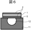
- Fig. 6 is a schematic diagram showing an enlarged view of the dotted rectangle 17-1 in Fig. 1C, illustrating the layer structure of the ion-sensitive membrane 17, which is characteristic of this embodiment.
- the ion-sensitive membrane 17 according to the second embodiment includes an anion-exchange membrane 1, an MPDA condensation layer 2 provided on both the upper and lower sides of the anion-exchange membrane 1, and an inactive layer 5 provided on the surface of the MPDA condensation layer 2 that comes into contact with the sample solution.
- the ion-sensitive membrane 17 is based on the anion-exchange membrane 1 having cations immobilized at a high density. First, the anion-exchange membrane 1 is immersed in a solution in which metaphenylenediamine is dissolved in a solvent.
- the anion exchange membrane 1 is immersed in a mixture of formaldehyde and an inorganic acid to form a condensate of metaphenylenediamine (MPDA) and formaldehyde in the ion exchange membrane.
- MPDA metaphenylenediamine
- the electrode housing 11 is filled with the internal gel 16
- the lid 18 is welded to the electrode housing 11, and the internal electrode 13 is fixed so as to contact the internal gel 16.
- the surface of the ion-sensitive membrane 17 on the opposite side to the flow path may be coated with a resin or the like.
- the anion exchange membrane 1 constituting the ion-sensitive membrane 17 in the second embodiment is a highly cross-linked polystyrene-based membrane having quaternary ammonium ions as anion exchange groups, and a membrane having a woven PVC (polyvinyl chloride) thread as a reinforcing material can be used.
- the ion exchange group may be a primary to tertiary amino group
- the base material may not be a styrene-based material but may be other hydrocarbon-based resins such as polyolefins or fluorine-based resins.
- the reinforcing material may also be other materials such as other polymer fibers or glass fibers, and the membrane may not have a reinforcing material.
- the counter ions contained in the anion exchange membrane 1 are preferably the same type of ions as the ions to be measured, but may be other anions. Furthermore, the effects of the technology disclosed herein can be achieved with any membrane that has a high density of fixed charges, even if it is not made of a material used in general ion exchange membranes.
- high density means that the charge density is about 0.1 to 10 mmol/g.
- the constituent material of the inactive layer 5 is insulating, it is formed to be appropriately thin, so that it is possible to create a state in which the permeation of ions is not completely insulated. In order to obtain the effect of suppressing the ion exchange reaction, a layer thickness of 0.10 ⁇ m or more is required. Furthermore, if the exchange of ions is completely blocked, there will be no ion response, so a portion with a layer thickness of 10 ⁇ m or less is required.
- the structure of the ion-sensitive membrane 17 according to the second embodiment is a structure in which the MPDA condensation layer 2 is added to the ion-sensitive membrane 17 according to the first embodiment.
- the MPDA condensation layer 2 plays a role in improving the ion selectivity of the ion-sensitive membrane 17 itself.
- the inactive layer 5 is formed on the MPDA condensation layer 2, so that the ion exchange reaction can be suppressed and the electrode characteristics during practical use can be made close to the ion selectivity of the membrane itself. Specific electrode performance will be described later.
- the materials used for the ion exchange membrane 1 and the inactive layer 5 can be selected from a variety of materials, similar to the first embodiment.
- the ion selective electrode 10 according to the second embodiment can be used in the above-mentioned electrolyte concentration measuring device 100 (see FIG. 3) in the same manner as the ion selective electrode 10 according to the first embodiment.
- Fig. 9 is a diagram showing an example of a cross-sectional configuration of a stick-type ion selective electrode 20 according to the third embodiment.
- the stick-type ion selective electrode 20 includes an electrode housing 22 with an opening (the opening at the bottom of FIG. 9).
- the stick-type ion selective electrode 20 includes an ion-sensitive membrane 17 that is disposed so as to cover the opening.
- the surface of the ion-sensitive membrane 17 that contacts the sample liquid is covered with an inactive layer 26.
- the electrode housing 22 includes an internal gel (internal liquid) 23 that contains an electrolyte so as to fill the inside of the electrode housing 22.
- An internal electrode 24 is disposed so as to contact the internal liquid 23, and a lid 25 is attached to confine the internal liquid 23 within the electrode housing 22.
- the ion selective electrode 20 is mounted on an electrolyte concentration measuring device 100 (see FIG. 3) and the internal electrode 24 is connected to wiring on the device 100 side, so that the potential generated according to the concentration of the ions to be measured contained in the sample liquid can be measured, and the concentration of the ions to be measured can be analyzed.
- the ion exchange membrane 21 having a fixed charge is coated with an inactive layer 26. At this time, the entire surface may be coated, or only the surface that comes into contact with the sample may be coated.
- the electrode housing 22 is filled with the internal gel (internal liquid) 23, the lid 25 is attached, and the internal electrode 24 is positioned so that it is in contact with the internal gel 23.
- the ion exchange membrane 21 may be previously subjected to a process for improving ion selectivity as described in the second embodiment (e.g., forming an MPDA condensation layer 2).
- the layer structure of the ion-sensitive membrane 17 according to this embodiment is similar to that of the first and second embodiments, so the ion-sensitive membrane 17 has the same characteristics in terms of slope sensitivity, ion selectivity, electrical resistance, service life, potential stability, and the like.
- Such a stick-type ion-selective electrode 20 is usually immersed together with a reference electrode in a container containing a sample liquid, and the sample liquid in the container is stirred with a stirrer while the potential is measured.
- the structure of this embodiment suppresses the ion exchange reaction between the ion-exchange membrane and the sample liquid, making it possible to practically achieve ion selectivity close to that of the ion-sensitive membrane itself, and also enabling measurements that are less dependent on the flow rate of the sample liquid.
- Other aspects such as the material composition, functions, and effects are the same as those of the first and second embodiments.
- FIG. 1A Configuration example of ion-selective electrode
- FIG. 1B is a diagram showing an example of the A-A' cross-sectional configuration of FIG. 1A.
- FIG. 1C is a diagram showing an example of the B-B' cross-sectional configuration.
- the flow-type ion-selective electrode of Comparative Example 1 has a flow path 12 penetrating an electrode housing 11, and a sample liquid to be measured passes through this flow path 12.
- An ion-sensitive membrane is provided so as to contact the sample liquid, and further, an internal gel 16 containing an electrolyte is provided so as to fill the inside of the electrode housing 11.
- An internal electrode 13 is provided so as to contact the internal gel 16, and a lid 18 is attached to confine the internal gel in the electrode housing.
- a packing 15 is provided near the inlet and outlet of the flow path 12 of the electrode housing so as to be connected to the flow path of the device or another electrode.
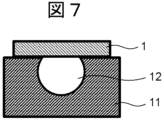
- FIG. 7 is an enlarged view of the dotted rectangle 17-1 in FIG. 1C, showing the layer structure of the ion-sensitive membrane of this comparative example.
- the ion-sensitive membrane of comparative example 1 is composed of an anion exchange membrane 1. Unlike the ion-sensitive membrane 17 of the first and second embodiments, it does not have an inactive layer 5.
- the anion exchange membrane 1 is a highly cross-linked polystyrene-based membrane having quaternary ammonium groups as anion exchange groups, and is reinforced with woven PVC (polyvinyl chloride) yarn fabric.
- the ion selective electrode manufactured in this manner has a structure in which the ion exchange membrane 1 is directly exposed to the sample liquid. Specific electrode performance will be described later.
- This Comparative Example 2 relates to the flow-type ion-selective electrode shown in Figures 1A to 1C, similar to that described in Comparative Example 1.
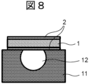
- Figure 8 is an enlarged view of the dotted rectangle 17-1 in Figure 1C, and shows the layer structure of the ion-sensitive membrane of this Comparative Example 2.
- the anion exchange membrane 1 is a highly cross-linked polystyrene-based membrane having quaternary ammonium groups as anion exchange groups, and is reinforced with woven PVC (polyvinyl chloride) yarn fabric.
- the ion-selective electrode manufactured in this manner has a structure in which the MPDA condensed ion exchange membrane 1 is in contact with the sample liquid.
- the specific electrode performance will be described later.
- the ion-selective electrode 10 having the structure according to the first embodiment showed a relatively stable potential for all liquids ( Figure 10 (a) to (h)).
- Fig. 11A is a diagram showing a schematic diagram of the ion composition inside the ion-sensitive membrane and sample solution of Comparative Example 1.
- Comparative Example 1 cations (positive ions) immobilized in the ion-exchange membrane 1 of the ion-sensitive membrane are present at high concentration, and chloride ions (Cl - ) are present as counter ions. Therefore, when the membrane comes into contact with a sample solution containing interfering ions J - , an ion exchange reaction occurs between the interfering ions J - in the sample solution near the membrane and the Cl - in the membrane. After the solution is allowed to stand still, the state changes from (a) in Fig. 11A to (b) as time passes.
- the ion-sensitive membrane is more responsive to Cl - than to HCO 3 - . Therefore, when HCO 3 - in the sample solution near the surface of the ion exchange membrane 1 is exchanged with Cl - , the ion-sensitive membrane senses (detects) that the ion concentration of the sample solution has increased. Since the slope sensitivity of an anion-selective electrode (the potential difference when the measurement target ion concentration is increased by one digit in FIG.
- FIG. 11A is a diagram showing a schematic diagram of the ion composition inside the ion-sensitive membrane 17 and the sample liquid in the case of an ion-selective electrode 10 having an inactive layer 5. Since the surface of the ion-sensitive membrane 17 is covered with the inactive layer 5, the ion exchange reaction between the ion exchange membrane 1 and the sample liquid is suppressed, and potential changes due to the ion exchange reaction as in Comparative Example 1 are less likely to occur.
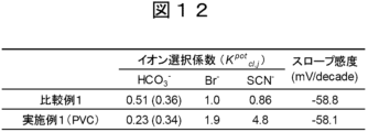
- FIG. 12 shows the results of calculating the slope and each interfering ion selectivity coefficient for chloride ion (Cl ⁇ ) from the potential value at a relatively stable timing after the second introduction of each sample solution in FIG. 10 (a numerical value indicating the degree of response of the interfering ion when chloride ion is set to 1).
- the numbers in parentheses indicate the selectivity calculation result at an ion concentration of 100 mM.
- the slope sensitivity was almost equivalent in both the ion selective electrode 10 (first embodiment) having the structure shown in FIG. 2 and the ion selective electrode (comparative example 1) having the structure shown in FIG. 7.
- the selectivity coefficient the selectivity for the hydrophilic ion HCO 3 ⁇ was low in the structure according to the first embodiment, and the selectivity coefficient for the hydrophobic ions Br ⁇ and SCN ⁇ was high, compared with comparative example 1. This is because in comparative example 1, the ion composition of the sample solution near the membrane changes due to the ion exchange reaction, and therefore a dull value is obtained in the actual measurement of the selectivity coefficient, whereas in the structure according to the first embodiment, the inactive layer can suppress the ion exchange reaction, and therefore a value close to the original selectivity coefficient of the ion-sensitive membrane 17 can be actually measured.
- a membrane with a high density of fixed charges such as the ion exchange membrane 1 according to this embodiment undergoes a rapid ion exchange reaction with the liquid.
- this ion exchange reaction is suppressed, making it possible to approach the original ion selectivity of the ion-sensitive membrane 17.
- FIG. 13 is a diagram showing the measurement results.
- the bicarbonate ion selectivity coefficient was evaluated by the so-called mixed solution method, which uses a sample solution in which an interfering ion has been added to a standard solution. For a chloride ion selective electrode, it is better for the selectivity coefficient of bicarbonate ion, which is an interfering ion, to be small. Note that a high-throughput automatic analyzer was used as the measuring device. This device dilutes the sample before performing the analysis.
- No. 1 shows the bicarbonate ion selectivity coefficient of an electrode equipped with an untreated ion exchange membrane 1 (electrode structure of Comparative Example 1).
- No. 2 shows the bicarbonate ion selectivity coefficient of an electrode equipped with a membrane in which only THF (containing no polymer) was applied to the surface of the ion exchange membrane 1 and dried (same as the electrode structure of Comparative Example 1).
- No. 3-9 show the bicarbonate ion selectivity coefficients of an electrode (structure of the first embodiment) equipped with a membrane in which a THF solution of PVC, Ethylene/vinyl acetate copolymer, Poly(vinyl formal), PVC+DOA, Ethylene/vinyl acetate copolymer+DOA, Poly(ethyl methacrylate)+DOA, and Poly(vinyl acetate)+DOA was dissolved and applied to the membrane surface and dried.
- a THF solution of PVC, Ethylene/vinyl acetate copolymer, Poly(vinyl formal), PVC+DOA, Ethylene/vinyl acetate copolymer+DOA, Poly(ethyl methacrylate)+DOA, and Poly(vinyl acetate)+DOA was dissolved and applied to the membrane surface and dried.
- electrodes No. 3 to No. 9 of the structure of the first embodiment have a smaller bicarbonate ion selectivity coefficient, and it is clear that their performance has been improved.
- inactive layer 5 on the surface of the ion exchange membrane 1, it is possible to bring out ion selectivity close to the original ion-sensitive membrane 17, regardless of the type of material of the inactive layer 5.
- the ion-sensitive membrane 17 of the structure of the first embodiment is inverted and assembled with the surface coated with the inactive layer 5 facing the internal gel 16, it has been confirmed that the ion-selective electrode 10 has a significantly larger bicarbonate ion selectivity coefficient than an electrode in which the surface coated with the inactive layer 5 faces the sample liquid. Therefore, it can be said that it is effective to form the inactive layer 5 between the ion exchange membrane 1 and the sample liquid.
- the bicarbonate ion (HCO 3 ⁇ ) selectivity coefficient relative to the chloride ion (Cl ⁇ ) was measured for the ion selective electrode having the structure according to Comparative Example 2 (see FIG. 8) and the ion selective electrode having the structure according to the second embodiment (see FIG. 6).
- FIG. 14 is a diagram showing the measurement results.
- the bicarbonate ion selectivity coefficient was evaluated by a so-called mixed solution method, in which a sample solution containing a standard solution to which an interfering ion was added is used.
- the selectivity coefficient for the interfering ion, bicarbonate ion is preferably small.
- FIG. 14 shows the average value of the bicarbonate ion selectivity coefficient in a bar graph, and the maximum and minimum values are shown by error bars.
- Blank shows results corresponding to the ion-selective electrode with the structure according to Comparative Example 2.
- this is a membrane in which a condensation layer 2 of MPDA and formaldehyde is formed on an anion exchange membrane 1, and no inactive layer is formed.
- the bicarbonate ion selectivity coefficient of this ion-selective electrode was about 0.19.
- An ion-sensitive membrane 17 (structure according to the second embodiment) in which an inactive layer 5 is formed on this ion-sensitive membrane with an average thickness of 0.1 ⁇ m showed no significant difference in the bicarbonate ion selectivity coefficient when compared to an ion-sensitive membrane not covered with an inactive layer 5 (corresponding to Comparative Example 2).
- the ion-sensitive membrane 17 in which the inactive layer 5 was formed with an average thickness of 1 ⁇ m showed a large improvement in the bicarbonate ion selectivity coefficient of approximately 0.09. Furthermore, the ion-sensitive membrane 17 in which the thickness of the inactive layer 5 was increased to 10 ⁇ m did not show a proper ion response because the inactive layer 5 was too thick, and the slope sensitivity showed an irregular value.
- the thickness of the inactive layer 5 should be between 0.1 and 10 ⁇ m.
- the ion-sensitive membrane 17 in which the inactive layer 5 is formed to an average thickness of 1 ⁇ m retains the effect of the inactive layer 5 even after storage, and maintains a low selectivity coefficient compared to the ion-sensitive membrane (comparative example) that is not covered with the inactive layer 5. In this way, the inactive layer 5 can be effective even after long-term storage.
- the ion-sensitive membrane in the ion-selective electrode contacts the sample liquid at least in part of the first surface, and contacts the internal gel (internal liquid) at least in part of the second surface (opposite the first surface) different from the first surface.
- the first surface of the ion-sensitive membrane is covered with an inactive layer that suppresses the ion exchange reaction between the ion-sensitive membrane and the sample liquid.
- the ions to be measured contained in the sample liquid are various anions and various cations.
- the ion-selective electrode is based on an ion exchange membrane (ion exchange resin) 1 that has a high density of fixed charge, and in this case, the charge density of the fixed charge can be 0.1 mmol/g or more.
- the inactive layer can be made of a material that is not ion-responsive.
- a material that is not ion-responsive can be an insulating material.
- An example of the insulating material can be a polymer material (a polymer containing carbon and hydrogen, or a material containing at least one of the elements chlorine and oxygen).
- the charge density of the inactive layer can be set to 0.001 mmol/g or less.
- the inactive layer has a portion with a thickness of 0.10 ⁇ m or more and 10 ⁇ m or less. By setting the thickness of the inactive layer within this range, it is possible to suppress the ion exchange reaction while reliably achieving an ion response.
- the ion-sensitive membrane may be composed of an ion exchange membrane 1, a treatment layer (e.g., an MPDA condensation layer) 2 formed on both sides of the ion exchange membrane 1 (the first side is the sample side, and the second side is the internal liquid side) to improve ion selectivity, and an inactive layer 5 formed on the condensation layer on the first side (second embodiment).
- a treatment layer e.g., an MPDA condensation layer
- an MPDA condensation layer formed on both sides of the ion exchange membrane 1 (the first side is the sample side, and the second side is the internal liquid side) to improve ion selectivity
- an inactive layer 5 formed on the condensation layer on the first side (second embodiment).
Landscapes
- Chemical & Material Sciences (AREA)
- Life Sciences & Earth Sciences (AREA)
- Health & Medical Sciences (AREA)
- Physics & Mathematics (AREA)
- Chemical Kinetics & Catalysis (AREA)
- Electrochemistry (AREA)
- Molecular Biology (AREA)
- Analytical Chemistry (AREA)
- Biochemistry (AREA)
- General Health & Medical Sciences (AREA)
- General Physics & Mathematics (AREA)
- Immunology (AREA)
- Pathology (AREA)
- Investigating Or Analyzing Materials By The Use Of Electric Means (AREA)
Priority Applications (3)
| Application Number | Priority Date | Filing Date | Title |
|---|---|---|---|
| CN202380072361.4A CN120019271A (zh) | 2022-11-07 | 2023-10-25 | 离子选择性电极和电解质浓度测定装置 |
| JP2024557302A JPWO2024101150A1 (https=) | 2022-11-07 | 2023-10-25 | |
| EP23887175.0A EP4617649A1 (en) | 2022-11-07 | 2023-10-25 | Ion-selective electrode, and electrolyte concentration measuring device |
Applications Claiming Priority (2)
| Application Number | Priority Date | Filing Date | Title |
|---|---|---|---|
| JP2022177764 | 2022-11-07 | ||
| JP2022-177764 | 2022-11-07 |
Publications (1)
| Publication Number | Publication Date |
|---|---|
| WO2024101150A1 true WO2024101150A1 (ja) | 2024-05-16 |
Family
ID=91032608
Family Applications (1)
| Application Number | Title | Priority Date | Filing Date |
|---|---|---|---|
| PCT/JP2023/038452 Ceased WO2024101150A1 (ja) | 2022-11-07 | 2023-10-25 | イオン選択性電極、および電解質濃度測定装置 |
Country Status (4)
| Country | Link |
|---|---|
| EP (1) | EP4617649A1 (https=) |
| JP (1) | JPWO2024101150A1 (https=) |
| CN (1) | CN120019271A (https=) |
| WO (1) | WO2024101150A1 (https=) |
Citations (5)
| Publication number | Priority date | Publication date | Assignee | Title |
|---|---|---|---|---|
| JPS56117355U (https=) * | 1980-02-12 | 1981-09-08 | ||
| JPS58186038A (ja) * | 1982-04-26 | 1983-10-29 | Toshiba Corp | イオン選択性電極 |
| JPH1010078A (ja) * | 1996-06-24 | 1998-01-16 | Hitachi Ltd | 塩素イオンセンサ |
| JPH10318973A (ja) * | 1997-05-15 | 1998-12-04 | Hitachi Ltd | 塩素イオン感応膜及びその製造方法 |
| JP2000329728A (ja) * | 1999-05-21 | 2000-11-30 | Hitachi Ltd | 陰イオン選択性電極、及びその保管方法、保管容器 |
Family Cites Families (1)
| Publication number | Priority date | Publication date | Assignee | Title |
|---|---|---|---|---|
| JP6783704B2 (ja) | 2017-05-31 | 2020-11-11 | 株式会社日立ハイテク | 陰イオン選択性電極及びその製造方法 |
-
2023
- 2023-10-25 CN CN202380072361.4A patent/CN120019271A/zh active Pending
- 2023-10-25 WO PCT/JP2023/038452 patent/WO2024101150A1/ja not_active Ceased
- 2023-10-25 EP EP23887175.0A patent/EP4617649A1/en active Pending
- 2023-10-25 JP JP2024557302A patent/JPWO2024101150A1/ja active Pending
Patent Citations (5)
| Publication number | Priority date | Publication date | Assignee | Title |
|---|---|---|---|---|
| JPS56117355U (https=) * | 1980-02-12 | 1981-09-08 | ||
| JPS58186038A (ja) * | 1982-04-26 | 1983-10-29 | Toshiba Corp | イオン選択性電極 |
| JPH1010078A (ja) * | 1996-06-24 | 1998-01-16 | Hitachi Ltd | 塩素イオンセンサ |
| JPH10318973A (ja) * | 1997-05-15 | 1998-12-04 | Hitachi Ltd | 塩素イオン感応膜及びその製造方法 |
| JP2000329728A (ja) * | 1999-05-21 | 2000-11-30 | Hitachi Ltd | 陰イオン選択性電極、及びその保管方法、保管容器 |
Non-Patent Citations (3)
| Title |
|---|
| KISHIOKA ATSUSHI, MATSUSHITA YUFUKU; MIYAKE MASAFUMI: "Detection of Interfering Ions Using Ion Flux Phenomena in Flow-Through Cl-ISEs with Ion Exchange Membranes", ANALYTICAL CHEMISTRY, AMERICAN CHEMICAL SOCIETY, US, vol. 95, no. 19, 16 May 2023 (2023-05-16), US , pages 7584 - 7593, XP093170626, ISSN: 0003-2700, DOI: 10.1021/acs.analchem.3c00366 * |
| See also references of EP4617649A1 * |
| SHIGERU ITOI: "Performance evaluation method for ion-exchange resin membranes", MEMBRAME, KITAMI SHOBO, TOKYO., JP, vol. 6, no. 3, 1 January 1981 (1981-01-01), JP , pages 47 - 58, XP093170624, ISSN: 0385-1036 * |
Also Published As
| Publication number | Publication date |
|---|---|
| EP4617649A1 (en) | 2025-09-17 |
| CN120019271A (zh) | 2025-05-16 |
| JPWO2024101150A1 (https=) | 2024-05-16 |
Similar Documents
| Publication | Publication Date | Title |
|---|---|---|
| EP3054290B1 (en) | Ion-selective electrode | |
| US10871464B2 (en) | Ion-selective electrode, method of manufacture thereof, and cartridge | |
| CA2038603A1 (en) | Metal-free buffer for ion selective electrode-based assays | |
| US4891125A (en) | Reference electrode and method of making it | |
| CN113677986B (zh) | 离子选择性电极及电解质浓度测定装置 | |
| US4597848A (en) | Electrode for measurement of ion activity | |
| US6719888B1 (en) | Reference electrode assembly | |
| KURUOGLU et al. | Hydrogen ion-selective poly (vinyl chloride) membrane electrode based on a calix [4] arene | |
| Bhakthavatsalam et al. | Selective coulometric release of ions from ion selective polymeric membranes for calibration-free titrations | |
| WO2023204088A1 (ja) | マイクロ分析チップ | |
| KR100511052B1 (ko) | 이온센서 및 그것을 사용한 생화학 자동분석장치 | |
| WO2024101150A1 (ja) | イオン選択性電極、および電解質濃度測定装置 | |
| EP0188319B1 (en) | Method and apparatus for measuring halogen ion concentration | |
| US6110338A (en) | Ion selective electrode apparatus and method of producing ion selective electrode apparatus | |
| EP0155162A2 (en) | Carbonate selective membrane and electrode | |
| JPWO2024101150A5 (https=) | ||
| EP0963550A1 (en) | Ion-selective electrode and method for selective determination of analytes in body fluids | |
| JP3121813U (ja) | 塩素イオンセンサ、その製造方法及びそのセンサを用いた生化学自動分析装置 | |
| US20260056162A1 (en) | Analytical device and method of measuring an electrolyte concentration | |
| JPS6140342B2 (https=) | ||
| JPH08211016A (ja) | 塩素イオン濃度の測定方法 | |
| JPH0256629B2 (https=) | ||
| JP6671213B2 (ja) | 自動分析装置および自動分析方法 | |
| JP2025540108A (ja) | 一価イオン選択電極センサ、膜組成物、および診断分析器のベンザルコニウム干渉を低減する方法 | |
| WO2025220551A1 (ja) | 分析デバイス及び分析方法 |
Legal Events
| Date | Code | Title | Description |
|---|---|---|---|
| 121 | Ep: the epo has been informed by wipo that ep was designated in this application |
Ref document number: 23887175 Country of ref document: EP Kind code of ref document: A1 |
|
| WWE | Wipo information: entry into national phase |
Ref document number: 2024557302 Country of ref document: JP |
|
| WWE | Wipo information: entry into national phase |
Ref document number: 202380072361.4 Country of ref document: CN |
|
| WWP | Wipo information: published in national office |
Ref document number: 202380072361.4 Country of ref document: CN |
|
| WWE | Wipo information: entry into national phase |
Ref document number: 2023887175 Country of ref document: EP |
|
| NENP | Non-entry into the national phase |
Ref country code: DE |
|
| ENP | Entry into the national phase |
Ref document number: 2023887175 Country of ref document: EP Effective date: 20250610 |
|
| WWP | Wipo information: published in national office |
Ref document number: 2023887175 Country of ref document: EP |