WO2024100959A1 - 交流電動機制御装置 - Google Patents
交流電動機制御装置 Download PDFInfo
- Publication number
- WO2024100959A1 WO2024100959A1 PCT/JP2023/030641 JP2023030641W WO2024100959A1 WO 2024100959 A1 WO2024100959 A1 WO 2024100959A1 JP 2023030641 W JP2023030641 W JP 2023030641W WO 2024100959 A1 WO2024100959 A1 WO 2024100959A1
- Authority
- WO
- WIPO (PCT)
- Prior art keywords
- carrier wave
- period
- motor
- control device
- generating unit
- Prior art date
- Legal status (The legal status is an assumption and is not a legal conclusion. Google has not performed a legal analysis and makes no representation as to the accuracy of the status listed.)
- Ceased
Links
Images


Classifications
-
- H—ELECTRICITY
- H02—GENERATION; CONVERSION OR DISTRIBUTION OF ELECTRIC POWER
- H02P—CONTROL OR REGULATION OF ELECTRIC MOTORS, ELECTRIC GENERATORS OR DYNAMO-ELECTRIC CONVERTERS; CONTROLLING TRANSFORMERS, REACTORS OR CHOKE COILS
- H02P27/00—Arrangements or methods for the control of AC motors characterised by the kind of supply voltage
- H02P27/04—Arrangements or methods for the control of AC motors characterised by the kind of supply voltage using variable-frequency supply voltage, e.g. inverter or converter supply voltage
- H02P27/06—Arrangements or methods for the control of AC motors characterised by the kind of supply voltage using variable-frequency supply voltage, e.g. inverter or converter supply voltage using DC to AC converters or inverters
- H02P27/08—Arrangements or methods for the control of AC motors characterised by the kind of supply voltage using variable-frequency supply voltage, e.g. inverter or converter supply voltage using DC to AC converters or inverters with pulse width modulation
-
- B—PERFORMING OPERATIONS; TRANSPORTING
- B60—VEHICLES IN GENERAL
- B60L—PROPULSION OF ELECTRICALLY-PROPELLED VEHICLES; SUPPLYING ELECTRIC POWER FOR AUXILIARY EQUIPMENT OF ELECTRICALLY-PROPELLED VEHICLES; ELECTRODYNAMIC BRAKE SYSTEMS FOR VEHICLES IN GENERAL; MAGNETIC SUSPENSION OR LEVITATION FOR VEHICLES; MONITORING OPERATING VARIABLES OF ELECTRICALLY-PROPELLED VEHICLES; ELECTRIC SAFETY DEVICES FOR ELECTRICALLY-PROPELLED VEHICLES
- B60L15/00—Methods, circuits, or devices for controlling the traction-motor speed of electrically-propelled vehicles
- B60L15/20—Methods, circuits, or devices for controlling the traction-motor speed of electrically-propelled vehicles for control of the vehicle or its driving motor to achieve a desired performance, e.g. speed, torque, programmed variation of speed
-
- H—ELECTRICITY
- H02—GENERATION; CONVERSION OR DISTRIBUTION OF ELECTRIC POWER
- H02P—CONTROL OR REGULATION OF ELECTRIC MOTORS, ELECTRIC GENERATORS OR DYNAMO-ELECTRIC CONVERTERS; CONTROLLING TRANSFORMERS, REACTORS OR CHOKE COILS
- H02P21/00—Arrangements or methods for the control of electric machines by vector control, e.g. by control of field orientation
- H02P21/05—Arrangements or methods for the control of electric machines by vector control, e.g. by control of field orientation specially adapted for damping motor oscillations, e.g. for reducing hunting
-
- H—ELECTRICITY
- H02—GENERATION; CONVERSION OR DISTRIBUTION OF ELECTRIC POWER
- H02P—CONTROL OR REGULATION OF ELECTRIC MOTORS, ELECTRIC GENERATORS OR DYNAMO-ELECTRIC CONVERTERS; CONTROLLING TRANSFORMERS, REACTORS OR CHOKE COILS
- H02P29/00—Arrangements for regulating or controlling electric motors, appropriate for both AC and DC motors
- H02P29/50—Reduction of harmonics
-
- B—PERFORMING OPERATIONS; TRANSPORTING
- B60—VEHICLES IN GENERAL
- B60L—PROPULSION OF ELECTRICALLY-PROPELLED VEHICLES; SUPPLYING ELECTRIC POWER FOR AUXILIARY EQUIPMENT OF ELECTRICALLY-PROPELLED VEHICLES; ELECTRODYNAMIC BRAKE SYSTEMS FOR VEHICLES IN GENERAL; MAGNETIC SUSPENSION OR LEVITATION FOR VEHICLES; MONITORING OPERATING VARIABLES OF ELECTRICALLY-PROPELLED VEHICLES; ELECTRIC SAFETY DEVICES FOR ELECTRICALLY-PROPELLED VEHICLES
- B60L2220/00—Electrical machine types; Structures or applications thereof
- B60L2220/10—Electrical machine types
-
- H—ELECTRICITY
- H02—GENERATION; CONVERSION OR DISTRIBUTION OF ELECTRIC POWER
- H02P—CONTROL OR REGULATION OF ELECTRIC MOTORS, ELECTRIC GENERATORS OR DYNAMO-ELECTRIC CONVERTERS; CONTROLLING TRANSFORMERS, REACTORS OR CHOKE COILS
- H02P2209/00—Indexing scheme relating to controlling arrangements characterised by the waveform of the supplied voltage or current
- H02P2209/09—PWM with fixed limited number of pulses per period
Definitions
- the present invention relates to an AC motor control device that drives an AC motor.
- PWM control is generally used as an AC motor control device to drive such AC motors.
- a modulation signal is created based on the voltage command signal applied to the AC motor, and a PWM pulse signal is created that turns the switching elements of the power conversion device on and off by comparing the modulation signal with the PWM carrier. This makes it possible to convert DC power into AC power that drives the AC motor.
- PWM control makes it possible to convert DC power to AC power, but because the switching elements of the power conversion device are repeatedly turned on and off at high speed, the output voltage is applied to the AC motor in pulses.
- the current flowing through an AC motor contains harmonic components, which cause noise and losses.
- Patent Document 1 Technologies for reducing noise and loss caused by turning on and off the switching elements of such power conversion devices are disclosed, for example, in Patent Document 1 and Patent Document 2.
- Patent Document 1 is configured to change the period of the PWM carrier over time. Meanwhile, the method described in Patent Document 2 is configured to shorten the period of the PWM carrier near the current zero crossing.
- PWM control causes harmonic components to be included in the current flowing through the AC motor, which can lead to increased noise and losses.
- Patent Documents 1 and 2 are capable of dispersing the harmonic components of the voltage applied in a pulsed manner to an AC motor, they do not disclose a configuration for actively suppressing the harmonic components of the current flowing through the AC motor.
- the object of the present invention is to realize an AC motor control device that can suppress the harmonic components of the current flowing through an AC motor and reduce the losses generated by the AC motor.
- the present invention is configured as follows:
- a power converter that converts DC power to AC power and a control unit that performs synchronous PWM control of an AC motor are included.
- the control unit has a carrier wave generation unit that generates a carrier wave, and a PWM pulse generation unit that generates a PWM pulse based on the carrier wave and a voltage command value.
- the carrier wave generation unit changes the period of the carrier wave so that harmonic components in the dq orthogonal coordinates of the AC motor contained in the PWM pulse are concentrated on the axis with the larger inductance, either the d axis or the q axis.
- an AC motor control device that can suppress the harmonic components of the current flowing through an AC motor and reduce the losses generated in the AC motor.
- FIG. 1 is a block diagram showing an overall configuration of an AC motor control device according to a first embodiment of the present invention
- FIG. 2 is a block diagram showing a PWM pulse generating unit according to the first embodiment of the present invention.
- FIG. 13 is a diagram showing an example of waveforms in a comparative example different from the present invention, in which the period of a carrier wave is constant during synchronous PWM control.
- 5A to 5C are diagrams illustrating an example of waveforms when the period of a carrier wave during synchronous PWM control is periodically changed in the first embodiment of the present invention.
- FIG. 2 is a schematic diagram showing the relationship between an orthogonal dq-axis coordinate system and voltages and currents in vector control.
- FIG. 11 is a diagram showing harmonic components of an output voltage when the period of a carrier wave is constant.
- 11A and 11B are diagrams illustrating harmonic components of an output voltage when the period of a carrier wave is periodically changed.
- 6B is a diagram showing current harmonic components that are generated when the voltage harmonic components shown in FIG. 6A are applied to an interior permanent magnet synchronous motor.
- FIG. 6C is a diagram showing current harmonic components that are generated when the voltage harmonic components shown in FIG. 6B are applied to an interior permanent magnet synchronous motor.
- 11 is a graph showing changes in current harmonic components when the amount of period change is changed.
- FIG. 11 is a diagram showing an example in which an AC motor control device according to a second embodiment of the present invention is applied to an electric vehicle.
- FIG. 11 is a configuration diagram of a PWM pulse generating unit in the second embodiment.
- Example 1 A first embodiment of the present invention will be described with reference to FIGS. 1 to 10.
- FIG. 1 A first embodiment of the present invention will be described with reference to FIGS. 1 to 10.
- This embodiment 1 describes an example in which an AC motor 1 is driven by an AC motor control device 10 of the present invention.
- FIG. 1 is a schematic diagram of an AC motor control device 10 according to a first embodiment.
- the AC motor control device 10 includes a control unit 2, an inverter (power converter) 3, and a current detection unit 4.
- the control unit 2 includes a vector control unit 21 and a PWM pulse generation unit 22.
- FIG. 2 is an explanatory diagram of the PWM pulse generation unit 22 included in the control unit 2, and the PWM pulse generation unit 22 includes a carrier wave generation unit 221 and a carrier voltage command comparison unit 222.
- the vector control unit 21 of the control unit 2 calculates a modulation rate command value (voltage command value) 21A based on information from a current detection unit 4 that detects the current flowing through the AC motor 1 and information 5A from a position sensor 5 that detects the rotational position of the AC motor 1.
- the PWM pulse generator 22 generates a PWM pulse 22A based on the calculated modulation rate command value 21A, and the inverter 3 converts DC power to AC power based on the generated PWM pulse 22A, and supplies AC power to the AC motor 1.
- a carrier wave such as a triangular wave is generated by the carrier wave generating unit 221, and the generated carrier wave is compared with the modulation rate command value 21A by the comparing unit 222 to generate a PWM pulse 22A.
- One method for controlling the AC motor 1 using PWM pulses is the synchronous PWM control method.
- the control unit 2 controls the AC motor 1 using synchronous PWM.
- Figure 3 shows a schematic diagram of the carrier wave and modulation factor command value during synchronous PWM control in a comparative example different from the present invention.
- the synchronous PWM control method fixes the number of PWM carrier waves contained in one rotation by changing the period of the PWM carrier wave according to the rotation speed of the AC motor.
- half a rotation of the AC modulation rate command (0° to 180°) contains 4.5 periods each of rising (peaks) and falling (valleys) of the carrier wave, and one rotation of the AC modulation rate command (0° to 360°) contains 9 periods each of rising (peaks) and falling (valleys) of the carrier wave, for a total of 18 periods.
- the period of the PWM carrier wave is generally set to a constant interval, and in the example configuration shown in Figure 3, this is called synchronous 9-pulse control.
- the use of a synchronous PWM control method has the advantage that the symmetry of the waveform is maintained and even-order harmonics are not generated.
- the configuration results in large voltage harmonic components being generated, such as the sideband waves of the first-order component of the carrier wave (6th and 12th order components in the example configuration shown in Figure 3) and the second-order component (18th order component in the example configuration shown in Figure 3).
- the period of the carrier wave during synchronous PWM control is periodically changed.
- FIG. 4 is a schematic diagram showing the synchronous 9-pulse period in which the period of the carrier wave of the synchronous PWM control according to the first embodiment of the present invention is periodically changed.
- the period of the carrier wave is configured to repeat a short period S and a long period L twice.
- the order of the period of the carrier wave is n
- the period of the carrier wave is set to change in a sixth order cycle as shown in the following equation (1).
- C which is multiplied by the sine wave function, is a value that corresponds to the amount of period change. Also, n is the order.
- Figure 5 shows an outline of the dq orthogonal coordinates and voltage/current during vector control.
- the dq orthogonal coordinate system is set with the d-axis in the magnet axis direction and the q-axis perpendicular to the magnet axis direction.
- voltage and current are controlled using such dq orthogonal coordinates.
- FIGS. 6A and 6B are diagrams showing the harmonic components of the output voltage when the period of the carrier wave is constant and when the period of the present application is periodically changed.
- FIG. 6A shows the case when the period is constant
- FIG. 6B shows the case when the period of the carrier wave of one embodiment is periodically changed.
- the horizontal axis in Figures 6A and 6B is the order, and the vertical axis is the amplitude.
- the solid line components in Figures 6A and 6B are the d-axis (magnet axial direction) components mentioned above, and the dotted lines are the q-axis (direction perpendicular to the magnet axis) components mentioned above.
- the component with the largest amplitude is the second-order component of the q-axis component (dotted line).
- the d-axis component (solid line) is generated to the left and right of the second-order component as sideband components of the first- and third-order components.
- a voltage containing harmonic components as shown in FIG. 6A or 6B is applied, and current harmonic components are generated due to the voltage harmonic components.
- the voltage and current related to the harmonic components have the relationship shown in the following equations (5) and (6) for the d-axis component (magnet axis direction) and q-axis (component perpendicular to the magnet axis).
- idh(n) is the d-axis current
- vdh(n) is the d-axis voltage
- Ldh is the d-axis inductance
- iqh(n) is the q-axis current
- vqh(n) is the q-axis voltage
- Lqh is the q-axis inductance
- interior permanent magnet synchronous motors are often used for the main motors that serve as the power source for on-board equipment.
- Such interior permanent magnet synchronous motors have a large salient pole ratio, with the q-axis inductance shown in formula (6) above being greater than the d-axis inductance shown in formula (5) above (Ldh ⁇ Lqh).
- the motor when voltage harmonics of the same amplitude are applied, the motor has characteristics in which the q-axis current harmonic component is smaller than the d-axis current harmonic component.
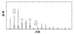
- FIGS. 7A and 7B show the current harmonic components that are generated when the voltage harmonic components shown in FIG. 6A and FIG. 6B are applied to such an interior permanent magnet synchronous motor.
- FIG. 7A shows the case where the period is constant
- FIG. 7B shows the case where the period of the carrier wave in one embodiment is changed periodically.
- the horizontal axis is the order
- the vertical axis is the amplitude.
- the solid line component is the d-axis (magnet axial direction) component
- the dotted line is the q-axis (direction perpendicular to the magnet axis) component.
- the second-order component of the q-axis component has the maximum voltage amplitude in the voltage harmonic components of Figure 6A, but because the q-axis inductance is large in an interior permanent magnet synchronous motor, the current amplitude of the q-axis second-order component in the current harmonic components of Figure 7A is small, and the current harmonic amplitude of the sideband wave of the first-order component of the d-axis is the maximum value.
- Example 1 in which the period of the carrier wave is periodically changed, as shown in FIG. 6B, the voltage harmonic component is shifted from the d-axis component to the q-axis component. Therefore, when a voltage according to one embodiment is applied to an interior permanent magnet synchronous motor, the d-axis current harmonic component decreases, as shown in FIG. 7B.
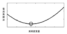
- FIG. 8 shows a schematic diagram in which the horizontal axis represents the period change amount C in the above formula (1) and the vertical axis represents the root mean square (RMS value) of the current harmonic components.
- the d-axis voltage harmonic components can be shifted to the q-axis voltage harmonic components as described above, and in an interior permanent magnet synchronous motor, the current harmonic components can be suppressed.
- the RMS value of the current harmonics versus the amount of period change is a downward convex function with a minimum point (shown by a circle in Figure 8).
- the carrier wave generating unit 221 sets the period change amount C, which is changed in the sixth period, to the point where the RMS value of the current harmonics is minimized, making it possible to drive the AC motor with the current harmonic components suppressed.
- the carrier wave generating unit 221 sets the period change amount changed in the sixth period to the period change amount at which the loss of the AC motor caused by the current harmonic components is minimized.
- the carrier wave generating unit 221 can be driven by setting a value smaller than the period change amount C that minimizes the current harmonic components and losses in the AC motor 1, thereby enabling driving that balances the suppression of changes between periods and decreases in control response with the suppression of current harmonic components and losses.
- the period of the carrier wave is changed at predetermined intervals so that the harmonic components in the dq orthogonal coordinates of the AC motor contained in the PWM pulse are concentrated on the axis side with the large inductance, thereby realizing an AC motor control device 10 that can reduce losses generated in the AC motor.
- the second embodiment is an example in which the present invention is applied to an AC motor control device that controls an AC motor of an electric vehicle.
- parts common to the first embodiment will not be illustrated or described.
- the rotating parts of the motor may freeze when started at extremely low temperatures, so a warm-up operation may be required. During such a warm-up operation, it is desirable for the loss generated by the motor to be large.
- PWM pulse generating unit 23 (a modified example of PWM pulse generating unit 2)
- AC motor temperature information 1A can be output to carrier wave switching unit 233 from a temperature sensor (not shown) that detects the temperature of AC motor 1.
- Carrier wave generating unit 231 can be defined as a fixed cycle carrier wave generating unit.
- the warm-up operation can be started earlier by configuring the PWM pulse generating unit 23 as described above.
- the q-axis inductance is greater than the d-axis inductance, but the invention can also be applied to cases where the d-axis inductance is greater than the q-axis inductance.
- the period of the PWM carrier wave is changed at a predetermined interval so that the harmonic components are concentrated on the d-axis side, which has the greater inductance.
Landscapes
- Engineering & Computer Science (AREA)
- Power Engineering (AREA)
- Transportation (AREA)
- Mechanical Engineering (AREA)
- Control Of Ac Motors In General (AREA)
Priority Applications (3)
| Application Number | Priority Date | Filing Date | Title |
|---|---|---|---|
| CN202380054476.0A CN119605074A (zh) | 2022-11-11 | 2023-08-25 | 交流电动机控制装置 |
| DE112023002834.6T DE112023002834T5 (de) | 2022-11-11 | 2023-08-25 | Ac-motor-steuerungseinrichtung |
| US19/110,640 US20260095115A1 (en) | 2022-11-11 | 2023-08-25 | AC Motor Control Device |
Applications Claiming Priority (2)
| Application Number | Priority Date | Filing Date | Title |
|---|---|---|---|
| JP2022-180805 | 2022-11-11 | ||
| JP2022180805A JP2024070365A (ja) | 2022-11-11 | 2022-11-11 | 交流電動機制御装置 |
Publications (1)
| Publication Number | Publication Date |
|---|---|
| WO2024100959A1 true WO2024100959A1 (ja) | 2024-05-16 |
Family
ID=91032131
Family Applications (1)
| Application Number | Title | Priority Date | Filing Date |
|---|---|---|---|
| PCT/JP2023/030641 Ceased WO2024100959A1 (ja) | 2022-11-11 | 2023-08-25 | 交流電動機制御装置 |
Country Status (5)
| Country | Link |
|---|---|
| US (1) | US20260095115A1 (https=) |
| JP (1) | JP2024070365A (https=) |
| CN (1) | CN119605074A (https=) |
| DE (1) | DE112023002834T5 (https=) |
| WO (1) | WO2024100959A1 (https=) |
Families Citing this family (1)
| Publication number | Priority date | Publication date | Assignee | Title |
|---|---|---|---|---|
| WO2026053416A1 (ja) * | 2024-09-09 | 2026-03-12 | 日産自動車株式会社 | モータ制御方法及びモータ制御装置 |
Citations (1)
| Publication number | Priority date | Publication date | Assignee | Title |
|---|---|---|---|---|
| JP2009011028A (ja) * | 2007-06-26 | 2009-01-15 | Toyota Motor Corp | モータ駆動システム |
-
2022
- 2022-11-11 JP JP2022180805A patent/JP2024070365A/ja active Pending
-
2023
- 2023-08-25 US US19/110,640 patent/US20260095115A1/en active Pending
- 2023-08-25 WO PCT/JP2023/030641 patent/WO2024100959A1/ja not_active Ceased
- 2023-08-25 CN CN202380054476.0A patent/CN119605074A/zh active Pending
- 2023-08-25 DE DE112023002834.6T patent/DE112023002834T5/de active Pending
Patent Citations (1)
| Publication number | Priority date | Publication date | Assignee | Title |
|---|---|---|---|---|
| JP2009011028A (ja) * | 2007-06-26 | 2009-01-15 | Toyota Motor Corp | モータ駆動システム |
Also Published As
| Publication number | Publication date |
|---|---|
| JP2024070365A (ja) | 2024-05-23 |
| US20260095115A1 (en) | 2026-04-02 |
| DE112023002834T5 (de) | 2025-04-17 |
| CN119605074A (zh) | 2025-03-11 |
Similar Documents
| Publication | Publication Date | Title |
|---|---|---|
| JP6695598B2 (ja) | インバータ制御装置 | |
| US11139771B2 (en) | Control device and control method for AC motor and AC motor drive system | |
| US20120206076A1 (en) | Motor-driving apparatus for variable-speed motor | |
| CN115868109B (zh) | 开放式绕组马达驱动装置 | |
| WO2011135694A1 (ja) | 電力変換装置 | |
| CN108988718B (zh) | 抑制零序电流和共模电压的方法 | |
| JP2014003783A (ja) | 電力変換器制御装置および多重巻線型電動機駆動装置 | |
| JP5845115B2 (ja) | モータ制御装置 | |
| CN110011581B (zh) | 一种非对称六相交流电机共模噪声的抑制方法和系统 | |
| JP2013085372A (ja) | 交流モータの制御装置および制御方法 | |
| JP2006121877A (ja) | モータ制御装置 | |
| WO2024100959A1 (ja) | 交流電動機制御装置 | |
| CN112567620B (zh) | 逆变装置 | |
| JP5808210B2 (ja) | モータ制御装置およびモータ制御方法 | |
| Vinod et al. | Direct torque control implemented on a three-level open-end winding induction motor drive | |
| JP5508943B2 (ja) | 電力変換装置 | |
| CN108023493B (zh) | 碳化硅逆变器共模电压幅值减小的方法和装置 | |
| KR101542960B1 (ko) | 친환경 자동차의 모터 제어 방법 및 장치 | |
| JP2008148395A (ja) | モータインバータ装置及びその制御方法 | |
| JP2005176566A (ja) | 単相誘導電動機の制御装置 | |
| Pei et al. | State-Complementary Switching Pattern-Based Modulation for Current-Ripple Reduction in SRM Drives Using Double-Updating Scheme | |
| WO2025084309A1 (ja) | 交流電動機制御装置 | |
| JP7680976B2 (ja) | 電力変換装置 | |
| CN109842332B (zh) | 一种新五边形接法的五相步进电机的控制方法 | |
| WO2025169560A1 (ja) | 電動機制御装置 |
Legal Events
| Date | Code | Title | Description |
|---|---|---|---|
| 121 | Ep: the epo has been informed by wipo that ep was designated in this application |
Ref document number: 23888314 Country of ref document: EP Kind code of ref document: A1 |
|
| WWE | Wipo information: entry into national phase |
Ref document number: 202380054476.0 Country of ref document: CN |
|
| WWE | Wipo information: entry into national phase |
Ref document number: 112023002834 Country of ref document: DE |
|
| WWP | Wipo information: published in national office |
Ref document number: 202380054476.0 Country of ref document: CN |
|
| WWP | Wipo information: published in national office |
Ref document number: 112023002834 Country of ref document: DE |
|
| 122 | Ep: pct application non-entry in european phase |
Ref document number: 23888314 Country of ref document: EP Kind code of ref document: A1 |