WO2024095433A1 - 内燃機関のシリンダヘッド構造 - Google Patents
内燃機関のシリンダヘッド構造 Download PDFInfo
- Publication number
- WO2024095433A1 WO2024095433A1 PCT/JP2022/041105 JP2022041105W WO2024095433A1 WO 2024095433 A1 WO2024095433 A1 WO 2024095433A1 JP 2022041105 W JP2022041105 W JP 2022041105W WO 2024095433 A1 WO2024095433 A1 WO 2024095433A1
- Authority
- WO
- WIPO (PCT)
- Prior art keywords
- camshaft
- cylinder head
- internal combustion
- combustion engine
- lash adjuster
- Prior art date
- Legal status (The legal status is an assumption and is not a legal conclusion. Google has not performed a legal analysis and makes no representation as to the accuracy of the status listed.)
- Ceased
Links
Images



Classifications
-
- F—MECHANICAL ENGINEERING; LIGHTING; HEATING; WEAPONS; BLASTING
- F01—MACHINES OR ENGINES IN GENERAL; ENGINE PLANTS IN GENERAL; STEAM ENGINES
- F01L—CYCLICALLY OPERATING VALVES FOR MACHINES OR ENGINES
- F01L1/00—Valve-gear or valve arrangements, e.g. lift-valve gear
Definitions
- This invention relates to a cylinder head structure for an internal combustion engine that is equipped with hydraulic lash adjusters for each of the intake valves and exhaust valves.
- Hydraulic lash adjusters are known for automatically adjusting valve clearance to zero in the valve mechanisms of intake and exhaust valves in internal combustion engines. In configurations where this hydraulic lash adjuster is provided in a cylinder head, the width dimension of the cylinder head tends to be large.
- Patent Document 1 discloses a configuration in which, in an internal combustion engine mounted horizontally on a vehicle, the exhaust camshaft, located toward the front of the vehicle, is positioned relatively lower than the intake camshaft, located toward the rear of the vehicle, to accommodate the inclination of the engine hood.
- the aim of this invention is to provide a more appropriate hydraulic lash adjuster arrangement when the two camshafts are positioned at different heights like this.
- the present invention relates to A cylinder head; a first camshaft and a second camshaft, one of which is for an intake valve and the other is for an exhaust valve; a first hydraulic lash adjuster provided corresponding to the first camshaft; a second hydraulic lash adjuster provided corresponding to the second camshaft;
- a cylinder head structure for an internal combustion engine comprising: The first camshaft is disposed at a lower height position along a cylinder central axis than the second camshaft, the second hydraulic lash adjuster is located inward in a width direction of the internal combustion engine with respect to a center line of a valve stem of a corresponding intake valve or exhaust valve which is inclined with respect to a central axis of the cylinder, The first hydraulic lash adjuster is located outboard of the center line of the valve stem of the corresponding intake valve or exhaust valve in the width direction of the internal combustion engine.
- the hydraulic lash adjuster is positioned outside the center line of the valve stem of the intake valve or exhaust valve in the width direction of the internal combustion engine, the outer edge of the cylinder head will protrude outward in the width direction of the internal combustion engine due to the addition of the hydraulic lash adjuster itself, the provision of the structure necessary to incorporate the hydraulic lash adjuster, the formation of an oil passage for oil supply, etc.
- the hydraulic lash adjusters on both the intake side and exhaust side inside the center line of the valve stem of the intake valve or exhaust valve in the width direction of the internal combustion engine, the width dimension of the cylinder head will instead expand in order to secure space for both.
- the second hydraulic lash adjuster corresponding to the second camshaft, which is in a relatively high position is located inside the center line of the valve stem in the width direction of the internal combustion engine
- the first hydraulic lash adjuster corresponding to the first camshaft, which is in a relatively low position is located outside the center line of the valve stem in the width direction of the internal combustion engine. Therefore, the outer edge of the cylinder head does not protrude outward as much on the side of the second camshaft, which is in a relatively high position, and therefore has little effect on the clearance between the engine hood when mounted on the vehicle.
- the outer edge of the cylinder head protrudes outward, but because this portion is in a relatively low position, it has little effect on vehicle mountability.
- FIG. 2 is a front view of a cylinder head equipped with a cam carrier.
- FIG. FIG. 4 is a cross-sectional view of a cylinder head equipped with a cam carrier.
- FIG. 4 is an explanatory diagram showing the layout of oil passages.
- FIG. 1 is a front view showing a cylinder head 1 of an internal combustion engine according to the present invention together with a cam carrier 2.
- the cylinder head 1 is integrally cast using a metal material, such as an aluminum alloy, and is attached to the upper surface of a cylinder block 3.
- the internal combustion engine of the embodiment is an in-line three-cylinder spark ignition internal combustion engine, a so-called gasoline engine, and is mounted in a so-called horizontal position at the front of a vehicle.
- the central axis of the cylinder is generally vertical, and therefore FIG. 1 generally corresponds to the position when mounted on the vehicle.
- the internal combustion engine of the embodiment has a pent roof type combustion chamber with a spark plug and a fuel injection valve in the center of the combustion chamber, and each cylinder has a pair of intake valves and a pair of exhaust valves.
- the cylinder head 1 is equipped with an intake camshaft 5 for the intake valves and an exhaust camshaft 6 for the exhaust valves.
- the cam carrier 2 is configured as a cover that covers the top opening of the cylinder head 1, and is joined and fixed to the top surface of the cylinder head 1 via an appropriate sealing member such as a liquid gasket.
- the cam carrier 2 has an intake side camshaft bearing portion 11 and an exhaust side camshaft bearing portion 12 that are roughly semicircular toward the bottom, and rotatably supports the intake camshaft 5 and the exhaust camshaft 6 between them and cam brackets 13 and 14 that are attached opposite these camshaft bearing portions 11 and 12.
- the intake camshaft 5 is positioned at a relatively lower height position along the cylinder center axis compared to the exhaust camshaft 6.
- the height position of the upper edge portion of the cam carrier 2 covering the upper part of each camshaft 5, 6 is also configured so that the intake camshaft 5 side is lower than the exhaust camshaft 6 side.
- the internal combustion engine is mounted in the engine room at the front of the vehicle with the intake camshaft 5 side facing the front of the vehicle and the exhaust camshaft 6 side facing the rear of the vehicle. Therefore, the clearance between the vehicle's engine hood (shown by imaginary line L), which is tilted so that the front end is in a low position, is appropriate on both the intake camshaft 5 side and the exhaust camshaft 6 side.
- the cam carrier 2 in one embodiment has a ladder-like configuration in which two camshaft housings 21, 22 that extend in the cylinder row direction are connected to each other at positions between the cylinders. At three locations that correspond to cylinder positions in the cylinder row direction, a relatively large injection valve opening 23 is provided between the two camshaft housings 21, 22.
- plug holes 24 for inserting spark plugs are each formed in a cylindrical shape on the exhaust camshaft 6 side (camshaft housing 22 side) of the injection valve opening 23.
- the cam carrier 2 is cast as a single unit using a metal material, such as an aluminum alloy.
- Figure 3 is a cross-sectional view of the cylinder head 1 and cam carrier 2 shown in Figure 1, cut along a cross section passing through the centers of the intake and exhaust valves. As mentioned above, it has a pent roof type combustion chamber 31, to which the intake port 32 and exhaust port 33 are connected.
- the valve mechanism is not shown in Figure 3, but as is well known to those skilled in the art, cylindrical stem guides are attached to the stem guide mounting holes 34, 35, respectively, and poppet valve type intake and exhaust valves are assembled together with valve springs.
- FIG. 5 is an explanatory diagram showing an outline of the valve mechanism not shown in FIG. 3.
- a rocker arm 101 one end of which is supported by the hydraulic lash adjuster 36, swings due to the cam action of the intake camshaft 5 to open and close the intake valve 103.
- a rocker arm 102 one end of which is supported by the hydraulic lash adjuster 37, swings due to the cam action of the exhaust camshaft 6 to open and close the exhaust valve 104.
- 105 indicates a fuel injection valve
- 106 indicates an ignition plug.
- the hydraulic lash adjuster itself is a well-known structure, so a detailed description is omitted, but it is roughly cylindrical, and is expanded by an internal spring to make the valve clearance zero, and the reaction force during valve lift is supported by the oil that fills the inside. Note that FIG. 5 is an explanatory diagram of the mechanism, and does not show the exact arrangement of each part.
- line M1 indicates the center line of the valve stem of the intake valve
- line M2 indicates the center line of the valve stem of the exhaust valve.
- the intake valve center line M1 and exhaust valve center line M2 are inclined with respect to the cylinder center axis so as to form a roughly symmetrical shape.
- the intake valve center line M1 passes inside the center O1 of the intake camshaft 5 in the width direction of the cylinder head 1 (left and right direction in FIG. 3).
- the exhaust valve center line M2 passes outside the center O2 of the exhaust camshaft 6 in the width direction of the cylinder head 1.
- width direction of the internal combustion engine in the claims and the above-mentioned “width direction of the cylinder head 1" are synonymous, and are a direction perpendicular to the cylinder center axis and perpendicular to the cylinder row direction.
- Hydraulic lash adjusters 36, 37 are provided for each of the intake valves and exhaust valves. These hydraulic lash adjusters 36, 37 are loaded into cylindrical lash adjuster mounting holes 38, 39 provided in the cylinder head 1 and receive hydraulic pressure.
- the intake side hydraulic lash adjuster 36 is located on the outside of the intake valve center line M1 in the width direction of the cylinder head 1, and in the illustrated example, is located approximately directly below the intake camshaft 5.
- the exhaust side hydraulic lash adjuster 37 is located on the inside of the exhaust valve center line M2 in the width direction of the cylinder head 1 (in other words, between center lines M2 and M1), and in the illustrated example, is located at a relatively higher position than the intake side hydraulic lash adjuster 36.
- the in-line three-cylinder cylinder head 1 is equipped with six intake hydraulic lash adjusters 36 and six exhaust hydraulic lash adjusters 37.
- the lash adjuster mounting holes 38, 39 are connected to lash adjuster oil galleries 41, 42 that extend in the cylinder row direction, respectively.
- the lash adjuster oil galleries 41, 42 are drilled, for example, along the cylinder row direction, and the ends of the lash adjuster oil galleries 41, 42 shown in Figure 1 are blocked by plugs.
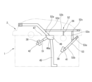
- Figure 4 shows the oil passages as seen through along the cylinder row direction to show the oil passages present inside the cylinder head 1 and cam carrier 2.
- these oil passages are constructed by a combination of linear drilling, with unnecessary open ends blocked by plugs.
- An oil source pressure passage 45 extending in the vertical direction is formed in approximately the center of the width of the cylinder head 1, in other words, at a position between the intake camshaft 5 and the exhaust camshaft 6 when viewed in the cylinder axial direction.
- the lower end of this oil source pressure passage 45 communicates with the main oil gallery (not shown) of the cylinder block 3. Therefore, oil pressurized by the oil pump is supplied to this oil source pressure passage 45.
- the upper end of the oil source pressure passage 45 opens into the underside of an oil reservoir 46 formed at the top of the cylinder head 1.
- the oil reservoir 46 is formed as a bathtub-shaped recess in the joint surface with the cam carrier 2 at a position between the intake camshaft 5 and the exhaust camshaft 6, and is covered by the underside of the cam carrier 2 to form a closed space.
- the joint surface 47 between the cylinder head 1 and the cam carrier 2 around the oil reservoir 46 is sealed with an appropriate sealing member such as the liquid gasket described above.
- the side surface 46a of the oil reservoir 46 on the exhaust camshaft 6 side is formed as an inclined surface as shown in FIG. 4, and one end of the exhaust-side oil passage 51 opens in the center of this side surface 46a.
- the exhaust-side oil passage 51 is formed in a straight line inclined, for example, at an angle of about 40 to 50 degrees with respect to the joint surface 47 (in other words, the top surface of the cylinder head 1), and its tip is connected to the exhaust-side lash adjuster oil gallery 42.
- oil is supplied to the exhaust-side lash adjuster mounting hole 39 from the oil reservoir 46 via the exhaust-side oil passage 51 and the lash adjuster oil gallery 42.
- the cam carrier 2 has a cam carrier internal passage 52 formed by connecting multiple straight sections so as to pass through the inside of the cam carrier 2 as part of the oil passage from the oil reservoir 46 to the intake side hydraulic lash adjuster 36.
- the cam carrier internal passage 52 is composed of a straight section 52a extending diagonally upward from the oil reservoir 46, a straight section 52b extending parallel to the joint surface 47 above the intake camshaft 5, and a straight section 52c extending downward outside the intake camshaft 5 in the width direction of the cylinder head 1.
- the cam carrier internal passage 52 has an inlet section 52d facing the oil reservoir 46 between the two camshafts 5, 6, and an outlet section 52e facing the top surface of the cylinder head 1 outside the two camshafts 5, 6.
- a camshaft lubricating oil passage 56 is formed that branches off from the cam carrier internal passage 52 and leads to the intake side camshaft bearing portion 11 for the intake camshaft 5.
- the journal portion of the intake camshaft 5 is lubricated by the oil that flows through this camshaft lubricating oil passage 56.
- An intake-side oil passage 53 is formed on the cylinder head 1 side so as to connect to the outlet 52e of the cam carrier internal passage 52.
- the intake-side oil passage 53 has a straight section 53a extending vertically and a straight section 53b extending diagonally downward from the outer periphery of the cylinder head 1.
- the tip of the straight section 53b is connected to the intake-side lash adjuster oil gallery 41.
- the periphery of the connection between the two is also sealed by a seal member at the joint surface 47 between the cylinder head 1 and the cam carrier 2. Therefore, oil is supplied to the intake-side lash adjuster mounting hole 38 from the oil reservoir 46 via the cam carrier internal passage 52, the intake-side oil passage 53, and the lash adjuster oil gallery 41.
- the intake camshaft 5 is positioned relatively lower than the exhaust camshaft 6, and the top surface of the cam carrier 2 is correspondingly shaped downward on the intake camshaft 5 side, so that as shown in FIG. 1, it is possible to ensure an appropriate clearance between the engine hood (imaginary line L), which is lower on the front side of the vehicle. In other words, it is possible to set the height of the engine hood lower.
- the exhaust-side hydraulic lash adjuster 37 corresponding to the exhaust camshaft 6, which is in a relatively high position, is located inside the cylinder head 1 in the width direction of the cylinder head 1 relative to the exhaust valve center line M2, and the outer edge position of the exhaust side of the cylinder head 1 is closer to the inside. In other words, the outer edge position of the exhaust side protrudes less outward in the width direction. This improves mountability on the vehicle. If the upper part of the cylinder head 1 or the rear part of the cam carrier 2 protruded toward the rear of the vehicle, mountability on the vehicle would be impaired, and as a result it would be difficult to lower the height of the engine hood.
- the arrangement of the embodiment is more advantageous in terms of lowering the height of the engine hood.
- the intake camshaft 5 and exhaust camshaft 6 are positioned closer to the rear of the vehicle in the embodiment than in the reference example. Therefore, the height of the part of the cam carrier 2 closer to the front of the vehicle is lowered accordingly, which is advantageous in terms of lowering the height of the engine hood.
- the exhaust camshaft 6 is located higher and closer to the front of the vehicle than in the embodiment, which reduces the clearance between the cam carrier 2 and the engine hood.
- oil is supplied to the intake side hydraulic lash adjuster 36, which is located on the outer side, through the cam carrier internal passage 52. Therefore, compared to forming all the necessary oil passages inside the cylinder head 1, the layout of the oil passages is easier, and the oil passages can be provided while avoiding interference with other parts.
- an intake valve is interposed between the oil source pressure passage 45 and the intake side lash adjuster mounting hole 38, but by providing the cam carrier internal passage 52 inside the cam carrier 2, it is possible to lay out the oil passages while avoiding interference with the intake valve.
- the cam carrier internal passage 52 crosses above the intake camshaft 5, it is not necessary to form an oil passage on the cylinder head 1 side that crosses below the camshaft 5, which is located at a relatively low position.
- the exhaust-side hydraulic lash adjuster 37 is located between the exhaust valve and the oil source pressure passage 45, so by providing an exhaust-side oil passage 51 in a straight line from the central oil reservoir 46 as described above, a simple structure can be achieved.
- the present invention is not limited to the above embodiment and various modifications are possible.
- the above embodiment has a ladder-shaped cam carrier 2, and the camshafts 5 and 6 are rotatably supported on the underside of the cam carrier 2 via cam brackets 13 and 14, but the configuration may also be such that the upper surface of the cylinder head 1 has a camshaft bearing portion, and the camshafts 5 and 6 are supported between the cam brackets attached to the cylinder head 1.
- the "first camshaft” in the claims is the intake camshaft 5 and the “second camshaft” is the exhaust camshaft 6, but conversely, the "first camshaft” located at a relatively low position may be the exhaust camshaft and the “second camshaft” located at a relatively high position may be the intake camshaft.
Landscapes
- Engineering & Computer Science (AREA)
- Mechanical Engineering (AREA)
- General Engineering & Computer Science (AREA)
- Valve-Gear Or Valve Arrangements (AREA)
- Cylinder Crankcases Of Internal Combustion Engines (AREA)
Priority Applications (3)
| Application Number | Priority Date | Filing Date | Title |
|---|---|---|---|
| JP2024554037A JP7841615B2 (ja) | 2022-11-04 | 2022-11-04 | 内燃機関のシリンダヘッド構造 |
| PCT/JP2022/041105 WO2024095433A1 (ja) | 2022-11-04 | 2022-11-04 | 内燃機関のシリンダヘッド構造 |
| CN202280101116.7A CN120051625A (zh) | 2022-11-04 | 2022-11-04 | 内燃机的气缸盖构造 |
Applications Claiming Priority (1)
| Application Number | Priority Date | Filing Date | Title |
|---|---|---|---|
| PCT/JP2022/041105 WO2024095433A1 (ja) | 2022-11-04 | 2022-11-04 | 内燃機関のシリンダヘッド構造 |
Publications (1)
| Publication Number | Publication Date |
|---|---|
| WO2024095433A1 true WO2024095433A1 (ja) | 2024-05-10 |
Family
ID=90930049
Family Applications (1)
| Application Number | Title | Priority Date | Filing Date |
|---|---|---|---|
| PCT/JP2022/041105 Ceased WO2024095433A1 (ja) | 2022-11-04 | 2022-11-04 | 内燃機関のシリンダヘッド構造 |
Country Status (3)
| Country | Link |
|---|---|
| JP (1) | JP7841615B2 (https=) |
| CN (1) | CN120051625A (https=) |
| WO (1) | WO2024095433A1 (https=) |
Citations (4)
| Publication number | Priority date | Publication date | Assignee | Title |
|---|---|---|---|---|
| JP2009062873A (ja) * | 2007-09-06 | 2009-03-26 | Toyota Motor Corp | 油圧式ラッシュアジャスタの潤滑油注入方法及び装置 |
| JP2013181521A (ja) * | 2012-03-05 | 2013-09-12 | Toyota Motor Corp | 高圧燃料ポンプの駆動装置 |
| JP2013181489A (ja) * | 2012-03-02 | 2013-09-12 | Toyota Motor Corp | 可変動弁機構の異常診断装置 |
| JP2017031916A (ja) * | 2015-08-04 | 2017-02-09 | トヨタ自動車株式会社 | 内燃機関の可変動弁装置 |
-
2022
- 2022-11-04 WO PCT/JP2022/041105 patent/WO2024095433A1/ja not_active Ceased
- 2022-11-04 CN CN202280101116.7A patent/CN120051625A/zh active Pending
- 2022-11-04 JP JP2024554037A patent/JP7841615B2/ja active Active
Patent Citations (4)
| Publication number | Priority date | Publication date | Assignee | Title |
|---|---|---|---|---|
| JP2009062873A (ja) * | 2007-09-06 | 2009-03-26 | Toyota Motor Corp | 油圧式ラッシュアジャスタの潤滑油注入方法及び装置 |
| JP2013181489A (ja) * | 2012-03-02 | 2013-09-12 | Toyota Motor Corp | 可変動弁機構の異常診断装置 |
| JP2013181521A (ja) * | 2012-03-05 | 2013-09-12 | Toyota Motor Corp | 高圧燃料ポンプの駆動装置 |
| JP2017031916A (ja) * | 2015-08-04 | 2017-02-09 | トヨタ自動車株式会社 | 内燃機関の可変動弁装置 |
Also Published As
| Publication number | Publication date |
|---|---|
| JP7841615B2 (ja) | 2026-04-07 |
| CN120051625A (zh) | 2025-05-27 |
| JPWO2024095433A1 (https=) | 2024-05-10 |
Similar Documents
| Publication | Publication Date | Title |
|---|---|---|
| JPH0122464B2 (https=) | ||
| US6796281B2 (en) | Internal combustion engine with valve train | |
| JP2623856B2 (ja) | 内燃機関のシリンダヘッド | |
| JP6713710B2 (ja) | スラント型内燃機関 | |
| JP4139693B2 (ja) | 燃料噴射式エンジンの燃料ポンプ取付け構造 | |
| JPH0668256B2 (ja) | Sohc型内燃機関 | |
| JP7841615B2 (ja) | 内燃機関のシリンダヘッド構造 | |
| JP2004028080A (ja) | エンジンのバルブスプリング支持構造 | |
| US4969427A (en) | Cylinder head of a four-cycle engine | |
| WO2024095432A1 (ja) | 内燃機関のシリンダヘッド構造 | |
| JP2024067071A (ja) | 内燃機関のシリンダヘッド構造 | |
| JPH068245Y2 (ja) | エンジンのシリンダヘッド構造 | |
| JP3142616B2 (ja) | 内燃機械の潤滑装置 | |
| JP3714465B2 (ja) | 内燃機関の一体型カムホルダ | |
| JPH0716004Y2 (ja) | 多気筒エンジンのシリンダヘッド | |
| JPH0392573A (ja) | 内燃機関のシリンダヘッド | |
| JP2502290B2 (ja) | Dohcエンジンのシリンダヘツド構造 | |
| JPH052809B2 (https=) | ||
| JP7356310B2 (ja) | 内燃機関 | |
| JPS63176611A (ja) | Dohc型内燃機関用シリンダヘツドにおける給油装置 | |
| JPS6212812Y2 (https=) | ||
| JPH0534506B2 (https=) | ||
| JP3117765B2 (ja) | 5バルブエンジンの動弁装置 | |
| JPH051807U (ja) | エンジンのシリンダヘツド構造 | |
| JP2506991Y2 (ja) | Dohcエンジンのシリンダヘッド |
Legal Events
| Date | Code | Title | Description |
|---|---|---|---|
| 121 | Ep: the epo has been informed by wipo that ep was designated in this application |
Ref document number: 22964450 Country of ref document: EP Kind code of ref document: A1 |
|
| WWE | Wipo information: entry into national phase |
Ref document number: 2024554037 Country of ref document: JP |
|
| WWE | Wipo information: entry into national phase |
Ref document number: 202280101116.7 Country of ref document: CN |
|
| WWP | Wipo information: published in national office |
Ref document number: 202280101116.7 Country of ref document: CN |
|
| NENP | Non-entry into the national phase |
Ref country code: DE |
|
| 122 | Ep: pct application non-entry in european phase |
Ref document number: 22964450 Country of ref document: EP Kind code of ref document: A1 |