WO2024095433A1 - 内燃機関のシリンダヘッド構造 - Google Patents
内燃機関のシリンダヘッド構造 Download PDFInfo
- Publication number
- WO2024095433A1 WO2024095433A1 PCT/JP2022/041105 JP2022041105W WO2024095433A1 WO 2024095433 A1 WO2024095433 A1 WO 2024095433A1 JP 2022041105 W JP2022041105 W JP 2022041105W WO 2024095433 A1 WO2024095433 A1 WO 2024095433A1
- Authority
- WO
- WIPO (PCT)
- Prior art keywords
- camshaft
- cylinder head
- internal combustion
- combustion engine
- lash adjuster
- Prior art date
Links
- 238000002485 combustion reaction Methods 0.000 title claims abstract description 30
- 239000003921 oil Substances 0.000 claims description 56
- 239000010687 lubricating oil Substances 0.000 claims description 3
- 238000002347 injection Methods 0.000 description 4
- 239000007924 injection Substances 0.000 description 4
- 230000007246 mechanism Effects 0.000 description 4
- 238000010586 diagram Methods 0.000 description 3
- 230000000694 effects Effects 0.000 description 3
- 229910000838 Al alloy Inorganic materials 0.000 description 2
- 239000000446 fuel Substances 0.000 description 2
- 239000007788 liquid Substances 0.000 description 2
- 239000007769 metal material Substances 0.000 description 2
- 238000007789 sealing Methods 0.000 description 2
- 230000015572 biosynthetic process Effects 0.000 description 1
- 238000006243 chemical reaction Methods 0.000 description 1
- 238000005553 drilling Methods 0.000 description 1
- 230000001771 impaired effect Effects 0.000 description 1
- 230000004048 modification Effects 0.000 description 1
- 238000012986 modification Methods 0.000 description 1
Images


Classifications
-
- F—MECHANICAL ENGINEERING; LIGHTING; HEATING; WEAPONS; BLASTING
- F01—MACHINES OR ENGINES IN GENERAL; ENGINE PLANTS IN GENERAL; STEAM ENGINES
- F01L—CYCLICALLY OPERATING VALVES FOR MACHINES OR ENGINES
- F01L1/00—Valve-gear or valve arrangements, e.g. lift-valve gear
Definitions
- This invention relates to a cylinder head structure for an internal combustion engine that is equipped with hydraulic lash adjusters for each of the intake valves and exhaust valves.
- Hydraulic lash adjusters are known for automatically adjusting valve clearance to zero in the valve mechanisms of intake and exhaust valves in internal combustion engines. In configurations where this hydraulic lash adjuster is provided in a cylinder head, the width dimension of the cylinder head tends to be large.
- Patent Document 1 discloses a configuration in which, in an internal combustion engine mounted horizontally on a vehicle, the exhaust camshaft, located toward the front of the vehicle, is positioned relatively lower than the intake camshaft, located toward the rear of the vehicle, to accommodate the inclination of the engine hood.
- the aim of this invention is to provide a more appropriate hydraulic lash adjuster arrangement when the two camshafts are positioned at different heights like this.
- the present invention relates to A cylinder head; a first camshaft and a second camshaft, one of which is for an intake valve and the other is for an exhaust valve; a first hydraulic lash adjuster provided corresponding to the first camshaft; a second hydraulic lash adjuster provided corresponding to the second camshaft;
- a cylinder head structure for an internal combustion engine comprising: The first camshaft is disposed at a lower height position along a cylinder central axis than the second camshaft, the second hydraulic lash adjuster is located inward in a width direction of the internal combustion engine with respect to a center line of a valve stem of a corresponding intake valve or exhaust valve which is inclined with respect to a central axis of the cylinder, The first hydraulic lash adjuster is located outboard of the center line of the valve stem of the corresponding intake valve or exhaust valve in the width direction of the internal combustion engine.
- the hydraulic lash adjuster is positioned outside the center line of the valve stem of the intake valve or exhaust valve in the width direction of the internal combustion engine, the outer edge of the cylinder head will protrude outward in the width direction of the internal combustion engine due to the addition of the hydraulic lash adjuster itself, the provision of the structure necessary to incorporate the hydraulic lash adjuster, the formation of an oil passage for oil supply, etc.
- the hydraulic lash adjusters on both the intake side and exhaust side inside the center line of the valve stem of the intake valve or exhaust valve in the width direction of the internal combustion engine, the width dimension of the cylinder head will instead expand in order to secure space for both.
- the second hydraulic lash adjuster corresponding to the second camshaft, which is in a relatively high position is located inside the center line of the valve stem in the width direction of the internal combustion engine
- the first hydraulic lash adjuster corresponding to the first camshaft, which is in a relatively low position is located outside the center line of the valve stem in the width direction of the internal combustion engine. Therefore, the outer edge of the cylinder head does not protrude outward as much on the side of the second camshaft, which is in a relatively high position, and therefore has little effect on the clearance between the engine hood when mounted on the vehicle.
- the outer edge of the cylinder head protrudes outward, but because this portion is in a relatively low position, it has little effect on vehicle mountability.
- FIG. 2 is a front view of a cylinder head equipped with a cam carrier.
- FIG. FIG. 4 is a cross-sectional view of a cylinder head equipped with a cam carrier.
- FIG. 4 is an explanatory diagram showing the layout of oil passages.
- FIG. 1 is a front view showing a cylinder head 1 of an internal combustion engine according to the present invention together with a cam carrier 2.
- the cylinder head 1 is integrally cast using a metal material, such as an aluminum alloy, and is attached to the upper surface of a cylinder block 3.
- the internal combustion engine of the embodiment is an in-line three-cylinder spark ignition internal combustion engine, a so-called gasoline engine, and is mounted in a so-called horizontal position at the front of a vehicle.
- the central axis of the cylinder is generally vertical, and therefore FIG. 1 generally corresponds to the position when mounted on the vehicle.
- the internal combustion engine of the embodiment has a pent roof type combustion chamber with a spark plug and a fuel injection valve in the center of the combustion chamber, and each cylinder has a pair of intake valves and a pair of exhaust valves.
- the cylinder head 1 is equipped with an intake camshaft 5 for the intake valves and an exhaust camshaft 6 for the exhaust valves.
- the cam carrier 2 is configured as a cover that covers the top opening of the cylinder head 1, and is joined and fixed to the top surface of the cylinder head 1 via an appropriate sealing member such as a liquid gasket.
- the cam carrier 2 has an intake side camshaft bearing portion 11 and an exhaust side camshaft bearing portion 12 that are roughly semicircular toward the bottom, and rotatably supports the intake camshaft 5 and the exhaust camshaft 6 between them and cam brackets 13 and 14 that are attached opposite these camshaft bearing portions 11 and 12.
- the intake camshaft 5 is positioned at a relatively lower height position along the cylinder center axis compared to the exhaust camshaft 6.
- the height position of the upper edge portion of the cam carrier 2 covering the upper part of each camshaft 5, 6 is also configured so that the intake camshaft 5 side is lower than the exhaust camshaft 6 side.
- the internal combustion engine is mounted in the engine room at the front of the vehicle with the intake camshaft 5 side facing the front of the vehicle and the exhaust camshaft 6 side facing the rear of the vehicle. Therefore, the clearance between the vehicle's engine hood (shown by imaginary line L), which is tilted so that the front end is in a low position, is appropriate on both the intake camshaft 5 side and the exhaust camshaft 6 side.
- the cam carrier 2 in one embodiment has a ladder-like configuration in which two camshaft housings 21, 22 that extend in the cylinder row direction are connected to each other at positions between the cylinders. At three locations that correspond to cylinder positions in the cylinder row direction, a relatively large injection valve opening 23 is provided between the two camshaft housings 21, 22.
- plug holes 24 for inserting spark plugs are each formed in a cylindrical shape on the exhaust camshaft 6 side (camshaft housing 22 side) of the injection valve opening 23.
- the cam carrier 2 is cast as a single unit using a metal material, such as an aluminum alloy.
- Figure 3 is a cross-sectional view of the cylinder head 1 and cam carrier 2 shown in Figure 1, cut along a cross section passing through the centers of the intake and exhaust valves. As mentioned above, it has a pent roof type combustion chamber 31, to which the intake port 32 and exhaust port 33 are connected.
- the valve mechanism is not shown in Figure 3, but as is well known to those skilled in the art, cylindrical stem guides are attached to the stem guide mounting holes 34, 35, respectively, and poppet valve type intake and exhaust valves are assembled together with valve springs.
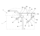
- FIG. 5 is an explanatory diagram showing an outline of the valve mechanism not shown in FIG. 3.
- a rocker arm 101 one end of which is supported by the hydraulic lash adjuster 36, swings due to the cam action of the intake camshaft 5 to open and close the intake valve 103.
- a rocker arm 102 one end of which is supported by the hydraulic lash adjuster 37, swings due to the cam action of the exhaust camshaft 6 to open and close the exhaust valve 104.
- 105 indicates a fuel injection valve
- 106 indicates an ignition plug.
- the hydraulic lash adjuster itself is a well-known structure, so a detailed description is omitted, but it is roughly cylindrical, and is expanded by an internal spring to make the valve clearance zero, and the reaction force during valve lift is supported by the oil that fills the inside. Note that FIG. 5 is an explanatory diagram of the mechanism, and does not show the exact arrangement of each part.
- line M1 indicates the center line of the valve stem of the intake valve
- line M2 indicates the center line of the valve stem of the exhaust valve.
- the intake valve center line M1 and exhaust valve center line M2 are inclined with respect to the cylinder center axis so as to form a roughly symmetrical shape.
- the intake valve center line M1 passes inside the center O1 of the intake camshaft 5 in the width direction of the cylinder head 1 (left and right direction in FIG. 3).
- the exhaust valve center line M2 passes outside the center O2 of the exhaust camshaft 6 in the width direction of the cylinder head 1.
- width direction of the internal combustion engine in the claims and the above-mentioned “width direction of the cylinder head 1" are synonymous, and are a direction perpendicular to the cylinder center axis and perpendicular to the cylinder row direction.
- Hydraulic lash adjusters 36, 37 are provided for each of the intake valves and exhaust valves. These hydraulic lash adjusters 36, 37 are loaded into cylindrical lash adjuster mounting holes 38, 39 provided in the cylinder head 1 and receive hydraulic pressure.
- the intake side hydraulic lash adjuster 36 is located on the outside of the intake valve center line M1 in the width direction of the cylinder head 1, and in the illustrated example, is located approximately directly below the intake camshaft 5.
- the exhaust side hydraulic lash adjuster 37 is located on the inside of the exhaust valve center line M2 in the width direction of the cylinder head 1 (in other words, between center lines M2 and M1), and in the illustrated example, is located at a relatively higher position than the intake side hydraulic lash adjuster 36.
- the in-line three-cylinder cylinder head 1 is equipped with six intake hydraulic lash adjusters 36 and six exhaust hydraulic lash adjusters 37.
- the lash adjuster mounting holes 38, 39 are connected to lash adjuster oil galleries 41, 42 that extend in the cylinder row direction, respectively.
- the lash adjuster oil galleries 41, 42 are drilled, for example, along the cylinder row direction, and the ends of the lash adjuster oil galleries 41, 42 shown in Figure 1 are blocked by plugs.
- Figure 4 shows the oil passages as seen through along the cylinder row direction to show the oil passages present inside the cylinder head 1 and cam carrier 2.
- these oil passages are constructed by a combination of linear drilling, with unnecessary open ends blocked by plugs.
- An oil source pressure passage 45 extending in the vertical direction is formed in approximately the center of the width of the cylinder head 1, in other words, at a position between the intake camshaft 5 and the exhaust camshaft 6 when viewed in the cylinder axial direction.
- the lower end of this oil source pressure passage 45 communicates with the main oil gallery (not shown) of the cylinder block 3. Therefore, oil pressurized by the oil pump is supplied to this oil source pressure passage 45.
- the upper end of the oil source pressure passage 45 opens into the underside of an oil reservoir 46 formed at the top of the cylinder head 1.
- the oil reservoir 46 is formed as a bathtub-shaped recess in the joint surface with the cam carrier 2 at a position between the intake camshaft 5 and the exhaust camshaft 6, and is covered by the underside of the cam carrier 2 to form a closed space.
- the joint surface 47 between the cylinder head 1 and the cam carrier 2 around the oil reservoir 46 is sealed with an appropriate sealing member such as the liquid gasket described above.
- the side surface 46a of the oil reservoir 46 on the exhaust camshaft 6 side is formed as an inclined surface as shown in FIG. 4, and one end of the exhaust-side oil passage 51 opens in the center of this side surface 46a.
- the exhaust-side oil passage 51 is formed in a straight line inclined, for example, at an angle of about 40 to 50 degrees with respect to the joint surface 47 (in other words, the top surface of the cylinder head 1), and its tip is connected to the exhaust-side lash adjuster oil gallery 42.
- oil is supplied to the exhaust-side lash adjuster mounting hole 39 from the oil reservoir 46 via the exhaust-side oil passage 51 and the lash adjuster oil gallery 42.
- the cam carrier 2 has a cam carrier internal passage 52 formed by connecting multiple straight sections so as to pass through the inside of the cam carrier 2 as part of the oil passage from the oil reservoir 46 to the intake side hydraulic lash adjuster 36.
- the cam carrier internal passage 52 is composed of a straight section 52a extending diagonally upward from the oil reservoir 46, a straight section 52b extending parallel to the joint surface 47 above the intake camshaft 5, and a straight section 52c extending downward outside the intake camshaft 5 in the width direction of the cylinder head 1.
- the cam carrier internal passage 52 has an inlet section 52d facing the oil reservoir 46 between the two camshafts 5, 6, and an outlet section 52e facing the top surface of the cylinder head 1 outside the two camshafts 5, 6.
- a camshaft lubricating oil passage 56 is formed that branches off from the cam carrier internal passage 52 and leads to the intake side camshaft bearing portion 11 for the intake camshaft 5.
- the journal portion of the intake camshaft 5 is lubricated by the oil that flows through this camshaft lubricating oil passage 56.
- An intake-side oil passage 53 is formed on the cylinder head 1 side so as to connect to the outlet 52e of the cam carrier internal passage 52.
- the intake-side oil passage 53 has a straight section 53a extending vertically and a straight section 53b extending diagonally downward from the outer periphery of the cylinder head 1.
- the tip of the straight section 53b is connected to the intake-side lash adjuster oil gallery 41.
- the periphery of the connection between the two is also sealed by a seal member at the joint surface 47 between the cylinder head 1 and the cam carrier 2. Therefore, oil is supplied to the intake-side lash adjuster mounting hole 38 from the oil reservoir 46 via the cam carrier internal passage 52, the intake-side oil passage 53, and the lash adjuster oil gallery 41.
- the intake camshaft 5 is positioned relatively lower than the exhaust camshaft 6, and the top surface of the cam carrier 2 is correspondingly shaped downward on the intake camshaft 5 side, so that as shown in FIG. 1, it is possible to ensure an appropriate clearance between the engine hood (imaginary line L), which is lower on the front side of the vehicle. In other words, it is possible to set the height of the engine hood lower.
- the exhaust-side hydraulic lash adjuster 37 corresponding to the exhaust camshaft 6, which is in a relatively high position, is located inside the cylinder head 1 in the width direction of the cylinder head 1 relative to the exhaust valve center line M2, and the outer edge position of the exhaust side of the cylinder head 1 is closer to the inside. In other words, the outer edge position of the exhaust side protrudes less outward in the width direction. This improves mountability on the vehicle. If the upper part of the cylinder head 1 or the rear part of the cam carrier 2 protruded toward the rear of the vehicle, mountability on the vehicle would be impaired, and as a result it would be difficult to lower the height of the engine hood.
- the arrangement of the embodiment is more advantageous in terms of lowering the height of the engine hood.
- the intake camshaft 5 and exhaust camshaft 6 are positioned closer to the rear of the vehicle in the embodiment than in the reference example. Therefore, the height of the part of the cam carrier 2 closer to the front of the vehicle is lowered accordingly, which is advantageous in terms of lowering the height of the engine hood.
- the exhaust camshaft 6 is located higher and closer to the front of the vehicle than in the embodiment, which reduces the clearance between the cam carrier 2 and the engine hood.
- oil is supplied to the intake side hydraulic lash adjuster 36, which is located on the outer side, through the cam carrier internal passage 52. Therefore, compared to forming all the necessary oil passages inside the cylinder head 1, the layout of the oil passages is easier, and the oil passages can be provided while avoiding interference with other parts.
- an intake valve is interposed between the oil source pressure passage 45 and the intake side lash adjuster mounting hole 38, but by providing the cam carrier internal passage 52 inside the cam carrier 2, it is possible to lay out the oil passages while avoiding interference with the intake valve.
- the cam carrier internal passage 52 crosses above the intake camshaft 5, it is not necessary to form an oil passage on the cylinder head 1 side that crosses below the camshaft 5, which is located at a relatively low position.
- the exhaust-side hydraulic lash adjuster 37 is located between the exhaust valve and the oil source pressure passage 45, so by providing an exhaust-side oil passage 51 in a straight line from the central oil reservoir 46 as described above, a simple structure can be achieved.
- the present invention is not limited to the above embodiment and various modifications are possible.
- the above embodiment has a ladder-shaped cam carrier 2, and the camshafts 5 and 6 are rotatably supported on the underside of the cam carrier 2 via cam brackets 13 and 14, but the configuration may also be such that the upper surface of the cylinder head 1 has a camshaft bearing portion, and the camshafts 5 and 6 are supported between the cam brackets attached to the cylinder head 1.
- the "first camshaft” in the claims is the intake camshaft 5 and the “second camshaft” is the exhaust camshaft 6, but conversely, the "first camshaft” located at a relatively low position may be the exhaust camshaft and the “second camshaft” located at a relatively high position may be the intake camshaft.
Landscapes
- Engineering & Computer Science (AREA)
- Mechanical Engineering (AREA)
- General Engineering & Computer Science (AREA)
- Valve-Gear Or Valve Arrangements (AREA)
- Cylinder Crankcases Of Internal Combustion Engines (AREA)
Abstract
車両に横置きに搭載される内燃機関において、吸気カムシャフト(5)は排気カムシャフト(6)よりも低い位置にあり、エンジンフード(L)とカムキャリア(2)との間に適切なクリアランスが得られる。排気側油圧ラッシュアジャスタ(37)は、排気弁の中心線(M2)よりもシリンダヘッド(1)の幅方向内側にある。吸気側油圧ラッシュアジャスタ(36)は、吸気弁の中心線(M1)よりもシリンダヘッド(1)の幅方向外側にある。シリンダヘッド(1)の幅方向の中央部にオイル元圧通路(45)が配置されており、オイル貯留部(46)に連通する。吸気側のラッシュアジャスタ(36)には、カムキャリア(2)内部を通るカムキャリア内部通路(52)を介してオイルが供給される。
Description
この発明は、吸気弁および排気弁の各々に対して油圧ラッシュアジャスタを備えた内燃機関のシリンダヘッド構造に関する。
内燃機関の吸気弁や排気弁の動弁機構において、バルブクリアランスを0に自動調整するために、油圧ラッシュアジャスタが知られている。この油圧ラッシュアジャスタをシリンダヘッドに備えた構成では、シリンダヘッドの幅方向寸法が大きくなりやすい。
一方、特許文献1には、車両に横置き姿勢で搭載される内燃機関において、エンジンフードの傾斜に対応するように、車両前方寄りに位置する排気側カムシャフトを車両後方寄りに位置する吸気側カムシャフトよりも相対的に低い位置に配置した構成が開示されている。
この発明は、このように2本のカムシャフトの高さ位置が異なる場合に、より適切な油圧ラッシュアジャスタの配置を提供することを目的としている。
この発明は、
シリンダヘッドと、
いずれか一方が吸気弁用で他方が排気弁用となる第1のカムシャフトおよび第2のカムシャフトと、
第1のカムシャフトに対応して設けられた第1の油圧ラッシュアジャスタと、
第2のカムシャフトに対応して設けられた第2の油圧ラッシュアジャスタと、
を備えた内燃機関のシリンダヘッド構造であって、
シリンダ中心軸線に沿った高さ位置として、第1のカムシャフトが第2のカムシャフトに比較して低い位置に配置されており、
上記第2の油圧ラッシュアジャスタは、シリンダ中心軸線に対し傾斜した対応する吸気弁ないし排気弁のバルブステムの中心線よりも内燃機関の幅方向内側に位置し、
上記第1の油圧ラッシュアジャスタは、対応する吸気弁ないし排気弁のバルブステムの中心線よりも内燃機関の幅方向外側に位置する。
油圧ラッシュアジャスタが、吸気弁ないし排気弁のバルブステムの中心線よりも内燃機関の幅方向外側に配置されると、油圧ラッシュアジャスタ自身の追加、油圧ラッシュアジャスタを組み込むために必要な構造の確保、オイル供給のためのオイル通路の形成、などによって、内燃機関の幅方向においてシリンダヘッドの外縁が外側に張り出した構成となる。一方、吸気側と排気側の双方について油圧ラッシュアジャスタを吸気弁ないし排気弁のバルブステムの中心線よりも内燃機関の幅方向内側に配置しようとすると、両者のスペースの確保のために、シリンダヘッドの幅方向寸法が逆に拡大してしまう。
本発明では、相対的に高い位置にある第2のカムシャフトに対応する第2の油圧ラッシュアジャスタは、バルブステム中心線よりも内燃機関の幅方向内側に位置し、相対的に低い位置にある第1のカムシャフトに対応する第1の油圧ラッシュアジャスタは、バルブステム中心線よりも内燃機関の幅方向外側に位置する。そのため、相対的に高い位置にある第2のカムシャフト側ではシリンダヘッド外縁の外側への張り出しが小さく、従って、車両搭載時のエンジンフードとの間のクリアランスへの影響が少ない。相対的に低い位置にある第1のカムシャフト側では、シリンダヘッド外縁が外側に張り出すことになるが、この部分は、相対的に低い位置であることから、車両搭載性への影響が少ない。
以下、この発明の一実施例を図面に基づいて詳細に説明する。図1は、この発明に係る内燃機関のシリンダヘッド1をカムキャリア2とともに示した正面図である。シリンダヘッド1は、金属材料例えばアルミニウム合金を用いて一体に鋳造されたものであり、シリンダブロック3の上面に取り付けられている。実施例の内燃機関は、直列3気筒の火花点火式内燃機関いわゆるガソリン機関であって、車両の前部にいわゆる横置き姿勢で搭載される。車両搭載状態では、シリンダ中心軸線は、概ね垂直となっており、従って、図1は概ね車両搭載状態での姿勢に対応している。
また、実施例の内燃機関は、燃焼室中央部に点火プラグと燃料噴射弁とを備えたペントルーフ型燃焼室を有しており、各気筒に対し、一対の吸気弁と一対の排気弁とを備えている。
シリンダヘッド1は、吸気弁用の吸気カムシャフト5と、排気弁用の排気カムシャフト6と、を備えている。カムキャリア2は、シリンダヘッド1の上面開口を覆うカバー状に構成されており、シリンダヘッド1の上面に液体ガスケット等の適当なシール部材を介して接合され、かつ固定されている。カムキャリア2は、下面へ向かう略半円形をなす吸気側カムシャフト軸受部11および排気側カムシャフト軸受部12を有し、これらのカムシャフト軸受部11,12に対向して取り付けられるカムブラケット13,14との間で、吸気カムシャフト5および排気カムシャフト6をそれぞれ回転可能に支持している。
図1に示すように、シリンダ中心軸線に沿った高さ位置として、排気カムシャフト6に比較して吸気カムシャフト5の方が相対的に低い位置に配置されている。これに対応して、各々のカムシャフト5,6の上方を覆うカムキャリア2の上縁部分の高さ位置も、吸気カムシャフト5側の方が排気カムシャフト6側よりも低くなるように構成されている。一実施例の内燃機関は、吸気カムシャフト5側が車両前方となり排気カムシャフト6側が車両後方となるような向きで車両前部のエンジンルーム内に搭載される。従って、前端部が低い位置となるように傾斜した車両のエンジンフード(仮想線Lで示す)との間のクリアランスが、吸気カムシャフト5側と排気カムシャフト6側との双方で適切なものとなる。
図2に示すように、一実施例のカムキャリア2は、気筒列方向に細長く延びた2つのカムシャフト収容部21,22が気筒間位置で互いに接続されてなるラダー状の構成を有している。気筒列方向で気筒位置に相当する3箇所においては、2つのカムシャフト収容部21,22の間に、それぞれ比較的大きな噴射弁用開口部23を備えている。また、噴射弁用開口部23よりも排気カムシャフト6側(カムシャフト収容部22側)に、点火プラグを挿入するためのプラグホール24がそれぞれ円筒状に形成されている。カムキャリア2は、金属材料例えばアルミニウム合金を用いて一体に鋳造されている。
図3は、図1に示したシリンダヘッド1およびカムキャリア2を吸気弁および排気弁の中心を通る断面に沿って切断した断面図である。前述したようにペントルーフ型の燃焼室31を有し、吸気ポート32および排気ポート33が接続されている。図3では、動弁機構は図示省略されているが、当業者には周知のように、ステムガイド取付孔34,35にそれぞれ円筒状のステムガイドが取り付けられ、ポペットバルブ型の吸気側および排気弁がバルブスプリングとともに組み付けられるようになっている。
図5は、図3に示されていない動弁機構の概略を示した説明図であり、油圧ラッシュアジャスタ36に一端が支持されたロッカアーム101が吸気カムシャフト5のカム作用によって揺動し、吸気弁103を開閉する。同様に、油圧ラッシュアジャスタ37に一端が支持されたロッカアーム102が排気カムシャフト6のカム作用によって揺動し、排気弁104を開閉する。105は燃料噴射弁を、106は点火プラグを、それぞれ示している。油圧ラッシュアジャスタ自体は公知の構成であるので、その詳細な説明は省略するが、略円筒形をなし、内部のスプリングによってバルブクリアランスを0とするように伸長するとともに、バルブリフト時の反力を内部に充満するオイルによって支承する構成となっている。なお、図5は、機構の説明図であり、各部の厳密な配置を示したものではない。
図3において、線M1は吸気弁のバルブステムの中心線を示し、線M2は排気弁のバルブステムの中心線を示す。これらの吸気弁中心線M1および排気弁中心線M2は、概ね対称形状をなすように、それぞれシリンダ中心軸線に対して傾斜している。図3に示すように、吸気弁中心線M1は吸気カムシャフト5の中心O1よりもシリンダヘッド1の幅方向(図3の左右方向)で内側を通過する。他方、排気弁中心線M2は排気カムシャフト6の中心O2よりもシリンダヘッド1の幅方向で外側を通過する。なお、請求項における「内燃機関の幅方向」と上記の「シリンダヘッド1の幅方向」とは同義であり、シリンダ中心軸線に直交し、かつ気筒列方向に直交する方向となる。
吸気弁および排気弁の各々に対し、油圧ラッシュアジャスタ36,37が設けられている。これらの油圧ラッシュアジャスタ36,37は、シリンダヘッド1に設けられた円筒形のラッシュアジャスタ装着孔38,39に装填されて油圧供給を受ける。
吸気側の油圧ラッシュアジャスタ36は、吸気弁中心線M1よりもシリンダヘッド1の幅方向外側に位置し、図示例では、吸気カムシャフト5の概ね直下の位置に配置されている。排気側の油圧ラッシュアジャスタ37は、排気弁中心線M2よりもシリンダヘッド1の幅方向内側(換言すれば中心線M2と中心線M1との間)に位置し、図示例では、吸気側油圧ラッシュアジャスタ36よりも相対的に高い位置に設けられている。
直列3気筒のシリンダヘッド1全体では、6個の吸気側油圧ラッシュアジャスタ36と6個の排気側油圧ラッシュアジャスタ37とを備えている。ラッシュアジャスタ装着孔38,39は、それぞれ、気筒列方向に延びたラッシュアジャスタ用オイルギャラリ41,42に連通している。ラッシュアジャスタ用オイルギャラリ41,42は、例えば、気筒列方向に沿ってドリル加工されたものであり、図1に描かれているラッシュアジャスタ用オイルギャラリ41,42の端部はプラグによって閉塞されている。
図4は、シリンダヘッド1およびカムキャリア2の内部に存在するオイル通路を示すために、気筒列方向に沿って透視した形でオイル通路を示している。ラッシュアジャスタ用オイルギャラリ41,42以外のこれらのオイル通路の大部分は、シリンダヘッド1およびカムキャリア2の前端部(図2において下側部分)に形成されている。なお、ラッシュアジャスタ用オイルギャラリ41,42と同様に、これらのオイル通路は、直線的なドリル加工の組み合わせによって構成され、不要な開口端部がプラグによって閉塞されている。
シリンダヘッド1の幅方向の略中央部、換言すればシリンダ軸方向に見たときに吸気カムシャフト5と排気カムシャフト6との間となる位置に、上下方向に延びたオイル元圧通路45が形成されている。このオイル元圧通路45の下端部は、シリンダブロック3の図示しないメインオイルギャラリに連通する。従って、オイルポンプで加圧されたオイルがこのオイル元圧通路45に供給される。
オイル元圧通路45の上端は、シリンダヘッド1の上部に形成されたオイル貯留部46の下面に開口している。オイル貯留部46は、吸気カムシャフト5と排気カムシャフト6との間となる位置において、カムキャリア2との接合面にバスタブ状の凹部として形成されおり、カムキャリア2下面によって覆われることで閉空間として形成されている。オイル貯留部46の周囲におけるシリンダヘッド1とカムキャリア2との間の接合面47は、上述した液体ガスケット等の適当なシール部材によってシールされている。
オイル貯留部46の排気カムシャフト6側の側面46aは図4に示すように傾斜面として形成されており、この側面46aの中央部に、排気側オイル通路51の一端が開口している。排気側オイル通路51は、接合面47(換言すればシリンダヘッド1上面)に対し例えば40~50°程度傾いた直線状に形成されており、先端が排気側のラッシュアジャスタ用オイルギャラリ42に連通している。つまり、排気側のラッシュアジャスタ装着孔39には、オイル貯留部46から排気側オイル通路51およびラッシュアジャスタ用オイルギャラリ42を介してオイルが供給される。
一方、カムキャリア2には、オイル貯留部46から吸気側の油圧ラッシュアジャスタ36に至るオイル通路の一部として、カムキャリア2の内部を通過するように、複数の直線区間を接続してなるカムキャリア内部通路52が形成されている。カムキャリア内部通路52は、オイル貯留部46から斜め上方へ延びた直線区間52aと、吸気カムシャフト5の上方において接合面47と平行に延びた直線区間52bと、吸気カムシャフト5よりもシリンダヘッド1幅方向外側において下方へ延びた直線区間52cと、から構成されている。つまり、カムキャリア内部通路52は、2本のカムシャフト5,6の間においてオイル貯留部46に臨む入口部52dと、2本のカムシャフト5,6の外側においてシリンダヘッド1上面へ向かう出口部52eと、を備える。また、接合面47と平行に延びた直線区間52cの中間部には、カムキャリア内部通路52から分岐して吸気カムシャフト5用の吸気側カムシャフト軸受部11に至るカムシャフト潤滑油路56が形成されている。このカムシャフト潤滑油路56を介して流れるオイルによって吸気カムシャフト5のジャーナル部が潤滑される。
上記のカムキャリア内部通路52の出口部52eと接続するように、シリンダヘッド1側には、吸気側オイル通路53が形成されている。吸気側オイル通路53は、上下方向に延びる直線区間53aと、シリンダヘッド1の外周部から斜め下方へ延びる直線区間53bと、を有する。直線区間53bの先端が吸気側のラッシュアジャスタ用オイルギャラリ41に連通している。なお、両者の接続部の周囲は、やはりシリンダヘッド1とカムキャリア2との間の接合面47におけるシール部材によってシールされている。従って、吸気側のラッシュアジャスタ装着孔38には、オイル貯留部46からカムキャリア内部通路52と吸気側オイル通路53とラッシュアジャスタ用オイルギャラリ41とを介してオイルが供給される。
このように、上記実施例では、吸気カムシャフト5が排気カムシャフト6に比較して相対的に低い位置となり、これに対応してカムキャリア2の上面形状が吸気カムシャフト5側で下方に下がった形状となるので、図1に示すように、車両前方側が低くなるエンジンフード(仮想線L)との間のクリアランスを適切に確保することができる。換言すれば、エンジンフードの高さをより低く設定することが可能となる。
ここで、相対的に高い位置にある排気カムシャフト6に対応する排気側の油圧ラッシュアジャスタ37は、排気弁中心線M2よりもシリンダヘッド1の幅方向内側にあり、それだけシリンダヘッド1の排気側の外縁位置が内側寄りとなる。換言すれば、排気側の外縁位置の幅方向外側への張り出しが少なくなる。これにより、車両への搭載性が良好となる。仮に、シリンダヘッド1の上部やカムキャリア2の車両後方側部分が車両後方へ張り出していると、車両への搭載性が悪化し、結果的にエンジンフードの高さを低くすることが困難となる。
一方、相対的に低い位置にある吸気カムシャフト5に対応する吸気側の油圧ラッシュアジャスタ36は、吸気弁中心線M1よりもシリンダヘッド1の幅方向外側にあるので、シリンダヘッド1の幅方向内側に位置する排気側油圧ラッシュアジャスタ37とのレイアウト上の干渉が回避される。このように油圧ラッシュアジャスタ36が吸気弁中心線M1よりもシリンダヘッド1の幅方向外側にあると、シリンダヘッド1の吸気側の外縁位置が外側寄りとなる傾向となるが、このように比較的低い位置においてシリンダヘッド1の吸気側の外縁位置が外側寄りとなっても、エンジンフード(仮想線L)との関係についての影響は少なく、エンジンフードの高さを制限する要因とならない。
換言すれば、2つの油圧ラッシュアジャスタ36,37のいずれか一方が外側寄りに配置されるという制約の下で、排気側油圧ラッシュアジャスタ37が内側で吸気側油圧ラッシュアジャスタ36が外側寄りとなった上記実施例の配置と、逆に排気側油圧ラッシュアジャスタ37が外側寄りで吸気側油圧ラッシュアジャスタ36が内側に配置された配置(これを参考例とする)と、を比較すると、実施例の配置の方がエンジンフードの高さをより低くする上で有利である。すなわち、実施例と参考例とでシリンダヘッド1の全幅が等しいものと仮定し、さらに、いずれの場合もシリンダヘッド1の排気側の外縁(つまり車両後方寄りの外縁)を基準として車両への搭載位置が定まるものと仮定すると、参考例に比較して実施例の方が吸気カムシャフト5および排気カムシャフト6が車両後方寄りに位置することとなる。そのため、これに対応してカムキャリア2の車両前方寄り部分の高さが低くなり、エンジンフードの高さを低くする上で有利である。参考例では、高い位置にある排気カムシャフト6が実施例に比較して車両前方寄りの配置となり、それだけカムキャリア2とエンジンフードとの間に得られるクリアランスが小さくなる。
また、上記実施例では、外側寄りに配置される吸気側の油圧ラッシュアジャスタ36へのオイル供給がカムキャリア内部通路52を通して行われる。そのため、必要なオイル通路全体をシリンダヘッド1内部に形成する場合に比較して、オイル通路のレイアウトが容易となり、他部品との干渉を避けてオイル通路を設けることができる。例えば、オイル元圧通路45と吸気側のラッシュアジャスタ装着孔38との間には吸気弁が介在するが、カムキャリア2の内部にカムキャリア内部通路52を設けることで、吸気弁との干渉を避けつつオイル通路をレイアウトすることが可能となる。さらに、カムキャリア内部通路52が吸気カムシャフト5の上方を横切っているので、シリンダヘッド1側には、比較的低い位置にあるカムシャフト5の下方を横切るオイル通路の形成が不要である。
排気側の油圧ラッシュアジャスタ37は、排気弁とオイル元圧通路45との間に位置しているので、上記のように中央部のオイル貯留部46から直線的に排気側オイル通路51を設けることで、簡単な構造となる。
以上、この発明の一実施例を説明したが、この発明は上記実施例に限定されるものではなく、種々の変更が可能である。例えば、上記実施例ではラダー状のカムキャリア2を備え、該カムキャリア2の下面側にカムブラケット13,14を介してカムシャフト5,6が回転自在に支持されているが、シリンダヘッド1の上面にカムシャフト軸受部を有し、シリンダヘッド1に取り付けられるカムブラケットとの間にカムシャフト5,6が支持される構成であってもよい。また、上記実施例では、請求項における「第1のカムシャフト」が吸気カムシャフト5であり、「第2のカムシャフト」が排気カムシャフト6であるが、逆に、相対的に低い位置にある「第1のカムシャフト」が排気カムシャフト、相対的に高い位置にある「第2のカムシャフト」が吸気カムシャフトであってもよい。
Claims (4)
- シリンダヘッドと、
いずれか一方が吸気弁用で他方が排気弁用となる第1のカムシャフトおよび第2のカムシャフトと、
第1のカムシャフトに対応して設けられた第1の油圧ラッシュアジャスタと、
第2のカムシャフトに対応して設けられた第2の油圧ラッシュアジャスタと、
を備えた内燃機関のシリンダヘッド構造であって、
シリンダ中心軸線に沿った高さ位置として、第1のカムシャフトが第2のカムシャフトに比較して低い位置に配置されており、
上記第2の油圧ラッシュアジャスタは、シリンダ中心軸線に対し傾斜した対応する吸気弁ないし排気弁のバルブステムの中心線よりも内燃機関の幅方向内側に位置し、
上記第1の油圧ラッシュアジャスタは、対応する吸気弁ないし排気弁のバルブステムの中心線よりも内燃機関の幅方向外側に位置する、
内燃機関のシリンダヘッド構造。 - シリンダヘッドの上部に固定されて上記の2本のカムシャフトを支持するカムキャリアをさらに備え、
シリンダ軸方向に見たときに、第1のカムシャフトと第2のカムシャフトとの間にシリンダヘッド内部のオイル元圧通路が位置し、
このオイル元圧通路から第1のラッシュアジャスタに至るオイル通路の一部が、カムキャリア内部通路として、上記カムキャリアの内部を通過している、
請求項1に記載の内燃機関のシリンダヘッド構造。 - 上記カムキャリア内部で上記カムキャリア内部通路から分岐して第1のカムシャフトの軸受部に至るカムシャフト潤滑油路を備える、
請求項2に記載の内燃機関のシリンダヘッド構造。 - 上記内燃機関は、第1のカムシャフトが第2のカムシャフトよりも車両前方寄りとなるようにして、車両前部に横置き姿勢で搭載される、
請求項1に記載の内燃機関のシリンダヘッド構造。
Priority Applications (1)
| Application Number | Priority Date | Filing Date | Title |
|---|---|---|---|
| PCT/JP2022/041105 WO2024095433A1 (ja) | 2022-11-04 | 2022-11-04 | 内燃機関のシリンダヘッド構造 |
Applications Claiming Priority (1)
| Application Number | Priority Date | Filing Date | Title |
|---|---|---|---|
| PCT/JP2022/041105 WO2024095433A1 (ja) | 2022-11-04 | 2022-11-04 | 内燃機関のシリンダヘッド構造 |
Publications (1)
| Publication Number | Publication Date |
|---|---|
| WO2024095433A1 true WO2024095433A1 (ja) | 2024-05-10 |
Family
ID=90930049
Family Applications (1)
| Application Number | Title | Priority Date | Filing Date |
|---|---|---|---|
| PCT/JP2022/041105 WO2024095433A1 (ja) | 2022-11-04 | 2022-11-04 | 内燃機関のシリンダヘッド構造 |
Country Status (1)
| Country | Link |
|---|---|
| WO (1) | WO2024095433A1 (ja) |
Citations (4)
| Publication number | Priority date | Publication date | Assignee | Title |
|---|---|---|---|---|
| JP2009062873A (ja) * | 2007-09-06 | 2009-03-26 | Toyota Motor Corp | 油圧式ラッシュアジャスタの潤滑油注入方法及び装置 |
| JP2013181489A (ja) * | 2012-03-02 | 2013-09-12 | Toyota Motor Corp | 可変動弁機構の異常診断装置 |
| JP2013181521A (ja) * | 2012-03-05 | 2013-09-12 | Toyota Motor Corp | 高圧燃料ポンプの駆動装置 |
| JP2017031916A (ja) * | 2015-08-04 | 2017-02-09 | トヨタ自動車株式会社 | 内燃機関の可変動弁装置 |
-
2022
- 2022-11-04 WO PCT/JP2022/041105 patent/WO2024095433A1/ja unknown
Patent Citations (4)
| Publication number | Priority date | Publication date | Assignee | Title |
|---|---|---|---|---|
| JP2009062873A (ja) * | 2007-09-06 | 2009-03-26 | Toyota Motor Corp | 油圧式ラッシュアジャスタの潤滑油注入方法及び装置 |
| JP2013181489A (ja) * | 2012-03-02 | 2013-09-12 | Toyota Motor Corp | 可変動弁機構の異常診断装置 |
| JP2013181521A (ja) * | 2012-03-05 | 2013-09-12 | Toyota Motor Corp | 高圧燃料ポンプの駆動装置 |
| JP2017031916A (ja) * | 2015-08-04 | 2017-02-09 | トヨタ自動車株式会社 | 内燃機関の可変動弁装置 |
Similar Documents
| Publication | Publication Date | Title |
|---|---|---|
| JPH0122464B2 (ja) | ||
| US6796281B2 (en) | Internal combustion engine with valve train | |
| JP2623856B2 (ja) | 内燃機関のシリンダヘッド | |
| JP4139693B2 (ja) | 燃料噴射式エンジンの燃料ポンプ取付け構造 | |
| JPH0668256B2 (ja) | Sohc型内燃機関 | |
| JP6713710B2 (ja) | スラント型内燃機関 | |
| WO2024095433A1 (ja) | 内燃機関のシリンダヘッド構造 | |
| JP2004028080A (ja) | エンジンのバルブスプリング支持構造 | |
| WO2024095432A1 (ja) | 内燃機関のシリンダヘッド構造 | |
| US4969427A (en) | Cylinder head of a four-cycle engine | |
| EP1344930B1 (en) | Internal combustion engine with fuel injection valve | |
| JP2024067071A (ja) | 内燃機関のシリンダヘッド構造 | |
| JPH068245Y2 (ja) | エンジンのシリンダヘッド構造 | |
| JP3142616B2 (ja) | 内燃機械の潤滑装置 | |
| JP3714465B2 (ja) | 内燃機関の一体型カムホルダ | |
| JPH0716004Y2 (ja) | 多気筒エンジンのシリンダヘッド | |
| JP7356310B2 (ja) | 内燃機関 | |
| JP2502290B2 (ja) | Dohcエンジンのシリンダヘツド構造 | |
| JPS63176612A (ja) | Dohc型内燃機関用シリンダヘツドにおける給油装置 | |
| JPH0392573A (ja) | 内燃機関のシリンダヘッド | |
| JPS63176611A (ja) | Dohc型内燃機関用シリンダヘツドにおける給油装置 | |
| JP3415180B2 (ja) | エンジンのシリンダヘッド構造 | |
| JPS6212812Y2 (ja) | ||
| JPH0534506B2 (ja) | ||
| JP3117765B2 (ja) | 5バルブエンジンの動弁装置 |