WO2024095406A1 - 回転電機のステータコア、固定子、および、回転電機 - Google Patents
回転電機のステータコア、固定子、および、回転電機 Download PDFInfo
- Publication number
- WO2024095406A1 WO2024095406A1 PCT/JP2022/041027 JP2022041027W WO2024095406A1 WO 2024095406 A1 WO2024095406 A1 WO 2024095406A1 JP 2022041027 W JP2022041027 W JP 2022041027W WO 2024095406 A1 WO2024095406 A1 WO 2024095406A1
- Authority
- WO
- WIPO (PCT)
- Prior art keywords
- core
- split
- fastening
- stator
- electric machine
- Prior art date
- Legal status (The legal status is an assumption and is not a legal conclusion. Google has not performed a legal analysis and makes no representation as to the accuracy of the status listed.)
- Ceased
Links
Images












Classifications
-
- H—ELECTRICITY
- H02—GENERATION; CONVERSION OR DISTRIBUTION OF ELECTRIC POWER
- H02K—DYNAMO-ELECTRIC MACHINES
- H02K1/00—Details of the magnetic circuit
- H02K1/06—Details of the magnetic circuit characterised by the shape, form or construction
- H02K1/12—Stationary parts of the magnetic circuit
- H02K1/14—Stator cores with salient poles
- H02K1/146—Stator cores with salient poles consisting of a generally annular yoke with salient poles
- H02K1/148—Sectional cores
-
- H—ELECTRICITY
- H02—GENERATION; CONVERSION OR DISTRIBUTION OF ELECTRIC POWER
- H02K—DYNAMO-ELECTRIC MACHINES
- H02K1/00—Details of the magnetic circuit
- H02K1/06—Details of the magnetic circuit characterised by the shape, form or construction
- H02K1/12—Stationary parts of the magnetic circuit
- H02K1/14—Stator cores with salient poles
-
- H—ELECTRICITY
- H02—GENERATION; CONVERSION OR DISTRIBUTION OF ELECTRIC POWER
- H02K—DYNAMO-ELECTRIC MACHINES
- H02K1/00—Details of the magnetic circuit
- H02K1/06—Details of the magnetic circuit characterised by the shape, form or construction
- H02K1/12—Stationary parts of the magnetic circuit
- H02K1/16—Stator cores with slots for windings
-
- H—ELECTRICITY
- H02—GENERATION; CONVERSION OR DISTRIBUTION OF ELECTRIC POWER
- H02K—DYNAMO-ELECTRIC MACHINES
- H02K1/00—Details of the magnetic circuit
- H02K1/06—Details of the magnetic circuit characterised by the shape, form or construction
- H02K1/12—Stationary parts of the magnetic circuit
- H02K1/18—Means for mounting or fastening magnetic stationary parts on to, or to, the stator structures
- H02K1/185—Means for mounting or fastening magnetic stationary parts on to, or to, the stator structures to outer stators
-
- H—ELECTRICITY
- H02—GENERATION; CONVERSION OR DISTRIBUTION OF ELECTRIC POWER
- H02K—DYNAMO-ELECTRIC MACHINES
- H02K2213/00—Specific aspects, not otherwise provided for and not covered by codes H02K2201/00 - H02K2211/00
- H02K2213/03—Machines characterised by numerical values, ranges, mathematical expressions or similar information
Definitions
- This application relates to a stator core, a stator, and a rotating electric machine.
- stator cores Conventional stator cores, stators, and rotating electric machines often use fan-shaped split cores that are divided in the circumferential direction for reasons such as improving material yield and improving the assembly of windings.
- the outer diameter of the stator core has fastening parts with fastening holes arranged to connect to the frame, and the split cores are often configured in a state where they are alternately wrapped around each other (brick laying) (see, for example, Patent Document 1).
- the number of divisions needs to be increased in order to improve the material yield of the split cores having fastening parts.
- the fastening parts located near both ends of the split core need to be made extremely small, which creates the problem that the number and shape of the fastening parts with the frame that serves as the housing cannot be designed freely. This creates the problem that it is not possible to achieve both improved material yield and freedom in designing the fastening parts.
- This application discloses technology to solve the problems described above, and aims to provide a stator core, stator, and rotating electric machine that can achieve both improved material yield and freedom in designing fastening parts.
- the stator core of the rotating electric machine disclosed in the present application comprises: A stator core for a rotating electric machine,
- the stator core is The core plate is formed by stacking multiple plates in the axial direction.
- the core plate is The rotor has a plurality of teeth and is divided in the circumferential direction.
- the number of divisions N (N is an integer) is four or more.
- the rotor is formed by arranging divided cores in contact with each other in the circumferential direction.
- a fastening portion is formed on the outer periphery of the core plate, the fastening portion protruding outward in the radial direction and having a fastening hole for fastening the core plates to each other in the stacking direction,
- the fastening portion is A number M (M is an integer) of three or more are formed in the circumferential direction, There is a relationship of N ⁇ M,
- the split core is the fastening portion includes a plurality of types of split cores with fastening portion that are arranged at a plurality of different positions away from a center line that connects a rotation central axis of the rotating electric machine and a circumferential center of the split core,
- the fastening portions of the fastening portion-equipped divided cores of different types are stacked on top and bottom in the stacking direction,
- the core plate is arranged such that the contact points of the split cores are arranged at different positions in the circumferential direction on the upper and lower sides in the stacking direction,
- stator disclosed in the present application is The rotor includes a stator core for the rotating electric machine described above, and a coil wound around a tooth of the stator core with an insulator interposed therebetween.
- rotating electric machine disclosed in the present application is The stator described above; and a rotor rotatably disposed opposite the stator with a gap therebetween.
- stator core of a rotating electric machine the stator, and the rotating electric machine disclosed in the present application, This allows for both improved material yield and greater freedom in designing the fastening parts.
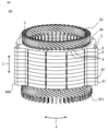
- FIG. 1 is a perspective view showing a configuration of a stator of a rotating electric machine according to a first embodiment
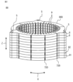
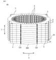
- 2 is a perspective view showing a configuration of a stator core of the rotating electric machine shown in FIG. 1
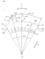
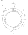
- 3 is a plan view showing the configuration of the stator core shown in FIG. 2.
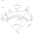
- 3 is a plan view showing a configuration of a first divided core of a core plate of the stator core shown in FIG. 2 .
- FIG. 3 is a plan view showing a configuration of a second divided core of a core plate of the stator core shown in FIG. 2 .
- FIG. 3 is a plan view showing a configuration of a fastening portion unsplit core of a core plate of the stator core shown in FIG. 2 .
- 3 is a plan view showing a configuration of a first-stage core plate of the stator core shown in FIG. 2.
- 3 is a plan view showing the configuration of a second-stage core plate of the stator core shown in FIG. 2.
- 3 is a plan view showing a configuration of a portion of the stator core shown in FIG. 2.
- 3 is a perspective view showing a configuration of a portion of the stator core shown in FIG. 2.
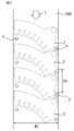
- 5 is a plan view showing a manufacturing method of the first split core shown in FIG. 4 .
- 6 is a plan view showing a manufacturing method of the second split core shown in FIG. 5 .
- 7 is a plan view showing a method for manufacturing the fastening portion unsplit core shown in FIG. 6 .
- FIG. 6 is a plan view showing a manufacturing method of the first split core and the second split core shown in FIGS. 4 and 5 .
- FIG. 7 is a plan view showing a manufacturing method of the first split core, the second split core, and the fastening portion non-split core shown in FIGS. 4, 5, and 6.
- FIG. FIG. 11 is a perspective view showing a configuration of a stator core of a rotating electric machine according to a second embodiment.
- 17 is a plan view showing the configuration of the stator core shown in FIG. 16.
- 17 is a plan view showing the configuration of a first-stage core plate of the stator core shown in FIG. 16.
- 17 is a plan view showing the configuration of a second-stage core plate of the stator core shown in FIG. 16.
- FIG. 11 is a perspective view showing a configuration of a stator core of a rotating electric machine according to embodiment 3.
- 22 is a plan view showing the configuration of the stator core shown in FIG. 21.
- 23 is a plan view showing the configuration of a first divided core of the stator core shown in FIG. 22.
- 23 is a plan view showing the configuration of a second split core of the stator core shown in FIG. 22.
- 23 is a plan view showing the configuration of a third divided core of the stator core shown in FIG. 22.
- 23 is a plan view showing the configuration of a fastening portion unsplit core of the stator core shown in FIG. 22.
- FIG. 22 is a plan view showing a first stage core plate configuration of the stator core shown in FIG. 21. 22 is a plan view showing a second-stage core plate configuration of the stator core shown in FIG. 21.
- FIG. 24 is a plan view showing a manufacturing method of the first split core shown in FIG. 23. 25 is a plan view showing a manufacturing method of the second split core shown in FIG. 24. 26 is a plan view showing a manufacturing method of the third split core shown in FIG. 25 .
- 27 is a plan view showing a method for manufacturing the fastening portion non-split core shown in FIG. 26.
- 13 is a plan view showing the configuration of a first-stage core plate of a stator core of a rotating electric machine according to embodiment 4.
- FIG. 13 is a plan view showing the configuration of a second-stage core plate of a stator core of a rotating electric machine according to embodiment 4.
- FIG. FIG. 13 is a perspective view showing the configuration of a stator core of a rotating electric machine according to embodiment 5.
- 36 is a plan view showing the configuration of the stator core shown in FIG. 35.
- 36 is a plan view showing the configuration of a first divided core of a core plate of the stator core shown in FIG. 35 .
- FIG. FIG. 36 is a plan view showing the configuration of a second divided core of the core plate of the stator core shown in FIG. 35 .
- 36 is a plan view showing the configuration of a first-stage core plate of the stator core shown in FIG. 35.
- FIG. 36 is a plan view showing the configuration of a second-stage core plate of the stator core shown in FIG. 35.
- FIG. 37 is a plan view showing another configuration of the second-stage core plate of the stator core shown in FIG. 35 .
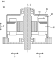
- 1 is a vertical cross-sectional view showing a configuration of a rotating electric machine according to an embodiment.
- 13 is a plan view showing a comparative example of a manufacturing method for a split core having three divisions.
- the stator core of the rotating electric machine in each embodiment is configured by arranging split cores of a rotating electric machine such as a motor in a circular ring shape. Therefore, in the following explanation, each direction in the rotating electric machine is indicated as the circumferential direction X, the axial direction Z, and the radial direction Y. These directions are the same in the stator core that constitutes the rotating electric machine and in other parts, and each direction will be explained based on these directions.
- Fig. 1 is a perspective view showing the configuration of a stator of a rotating electric machine according to a first embodiment.
- Fig. 2 is a perspective view showing the configuration of a stator core of the rotating electric machine shown in Fig. 1.
- Fig. 3 is a plan view showing the configuration of the stator core shown in Fig. 2.
- Fig. 4 is a plan view showing the configuration of a first divided core of a core plate of the stator core shown in Fig. 2.
- Fig. 5 is a plan view showing the configuration of a second divided core of a core plate of the stator core shown in Fig. 2.
- Fig. 6 is a plan view showing the configuration of a fastening portion undivided core of a core plate of the stator core shown in Fig. 2.
- FIG. 7 is a plan view showing the configuration of the first-stage core plate of the stator core shown in FIG. 2.
- FIG. 8 is a plan view showing the configuration of the second-stage core plate of the stator core shown in FIG. 2.
- FIG. 9 is a plan view showing the configuration of a portion of the stator core shown in FIG. 2.
- FIG. 10 is a perspective view showing the configuration of a portion of the stator core shown in FIG. 2.
- FIG. 11 is a plan view showing a method of manufacturing the first split core shown in FIG. 4.
- FIG. 12 is a plan view showing a method of manufacturing the second split core shown in FIG. 5.
- FIG. 13 is a plan view showing a method of manufacturing the fastening portion unsplit core shown in FIG. 6.
- FIG. 14 is a plan view showing a manufacturing method for the first and second split cores shown in FIGS. 4 and 5.
- FIG. 15 is a plan view showing a manufacturing method for the first and second split cores and the fastening portion unsplit core shown in FIGS. 4, 5 and 6.
- FIG. 42 is a vertical cross section showing the configuration of a rotating electric machine according to an embodiment.
- FIG. 43 is a plan view showing a comparative example of a manufacturing method for a split core with three divisions.
- a rotating electric machine 90 includes a stator 91 and a rotor 92 that is rotatably arranged opposite the stator 91 with a gap therebetween.
- the stator 91 is fixed to a frame 95.
- the rotor 92 rotates about a central axis of rotation Q.
- the stator 91 of the rotating electric machine 90 includes a stator core 80 and coils 93 formed of a conductor, such as a copper wire, in slots surrounded by teeth 9 in the circumferential direction X of the stator core 80 with an insulator (insulating paper) 94 between them.
- the figure shows an example in which the coils 93 are formed of rectangular wire, but this is not limited to this and they may be formed of round copper wire or aluminum wire.
- a terminal portion 931 is formed by joining the peeled-off portions, and the circuit of the rotating electric machine 90 shown in FIG. 42 is formed.
- the stator core 80 is formed by stacking multiple core plates 8 made of thin plates such as electromagnetic steel sheets (thickness of 0.25 mm to 0.3 mm or less) in the axial direction Z. Therefore, the axial direction Z corresponds to the stacking direction.
- the first row in the axial direction Z i.e., the bottom core plate 8 on the paper of FIG. 2
- the second row core plate 8 from the bottom on the paper of FIG. 2 i.e., the core plate 8 directly above the first row core plate 81 in the axial direction Z on the paper of FIG. 2
- the second row core plate 82 the core plate 8 directly above the first row core plate 81 in the axial direction Z on the paper of FIG.
- N is an integer
- N 6
- the core plates 8 constituting the stator core 80 have fastening portions 5 formed on the outer peripheral surface 800, which protrude outward in the radial direction Y and have fastening holes 51 for fastening the core plates 8 together in the axial direction Z.
- the number M (M is an integer) of fastening portions 5 of the core plates 8 in the circumferential direction X is 3 or more.
- the number M of fastening portions 5 of the core plates 8 is 3. Therefore, there is a relationship of N ⁇ M, and within that, there is a relationship of N > M.
- the fastening holes 51 of the fastening portion 5 are used as through holes for fastening the stator core 80 to the frame 95 shown in FIG. 35. It is also conceivable that a thick portion may be formed around the fastening holes 51 of the fastening portion 5 to ensure the rigidity of the fastening portion 5.
- the fastening portions 5 and fastening holes 51 are also shown and explained in the same manner for the stator core 80, the core plate 8, and the corresponding split cores 10 shown below.
- the split core 10 is configured with three types of split cores 10.
- the three types of split cores 10 include a first split core 1 and a second split core 2 as multiple types of split cores with fastening parts arranged at multiple different positions away from a center line Q1 that connects the rotational center axis Q of the rotating electric machine 90 and the center of the split core 10 in the circumferential direction X, and further include a fastening part non-split core 3 in which no fastening part 5 is formed.
- the length D1 from the rotation axis Q to the outer circumferential surface 100 of the first split core 1 corresponds to the radius of the core plate 8.
- the fastening portion 5 is formed to protrude from the outer circumferential surface 100 by a length D2 in the radial direction Y outward from the length D1.
- the relationship between length D1 and length D2 is the same in the following cases, so its description will be omitted as appropriate.
- outer peripheral recesses 72 are formed on the outer peripheral surface 100 of the first split core 1 on the center line Q1 and at both ends in the circumferential direction X.
- the outer peripheral recesses 72 are used for positioning or for welding the core plates 8 together in the axial direction Z.
- a convex portion 111 is formed on one abutment portion 101 that abuts against another split core 10 in the circumferential direction X of the first split core 1, and a concave portion 112 is formed on the other abutment portion 102.
- the convex portion 111 and the concave portion 112 are used for positioning the various split cores 10 together in the radial direction Y and for distinguishing between the front and back.
- outer peripheral recesses 72 are formed on the outer peripheral surface 200 of the second split core 2 on the center line Q1 and at both ends in the circumferential direction X.
- the outer peripheral recesses 72 are used for positioning or for welding the core plates 8 together in the axial direction Z.
- a convex portion 211 is formed on one abutment portion 201 that abuts against another split core 10 in the circumferential direction X of the second split core 2
- a concave portion 212 is formed on the other abutment portion 202.
- the convex portion 211 and the concave portion 212 are used for positioning the various split cores 10 together in the radial direction Y and for distinguishing between the front and back.
- the fastening portion unsplit core 3 does not have a fastening portion 5.
- outer peripheral recesses 72 are formed on the outer peripheral surface 300 of the fastening portion unsplit core 3 on the center line Q1 and at both ends in the circumferential direction X.
- the outer peripheral recesses 72 are used for positioning or welding the core plates 8 together in the axial direction Z.
- a convex portion 311 is formed on one abutment portion 301 that abuts against another split core 10 in the circumferential direction X of the fastening portion unsplit core 3, and a recess 312 is formed on the other abutment portion 302.
- the convex portion 311 and the recess 312 are used for positioning the various split cores 10 together in the radial direction Y and for distinguishing between the front and back.
- the first-stage core plate 81 of the stator core 80 is formed by alternately arranging the second split cores 2 and the fastening portion unsplit cores 3 in the circumferential direction X.
- the second-stage core plate 82 of the stator core 80 is formed by alternately arranging the first split cores 1 and the fastening portion unsplit cores 3 in the circumferential direction X.
- the stator core 80 is formed by sequentially stacking the first-stage core plate 81 and the second-stage core plate 82 in the axial direction Z.
- the fastening portions 5 of the split cores 10 of different types are stacked above and below in the axial direction Z.
- the stator core 80 is formed with a lap structure (brick-laid state) with alternating abutment points L1 and L2 in the axial direction Z, ensuring the rigidity of the stator core 80.
- first split core 1, the second split core 2, and the fastening portion unsplit core 3 each have an outer peripheral recess 72 formed on the center line Q1 and at both ends in the circumferential direction X, so that, as shown in Figures 2 and 10, the stator core 80 has a groove 720 formed on the outer peripheral surface 800 at the outer peripheral recess 72 that is connected in the axial direction Z.
- the core plates 8 are fixed together in the axial direction Z (stacking direction) by crimping, welding, adhesives, etc.
- adhesives make it easier to obtain the rigidity required for the stator 91, so welding, which will be described later, does not need to be performed.
- welding is performed in the grooves 720 in the axial direction Z, as shown above.
- the grooves 720 can also be used to position the split cores 10. Note that laser welding or other common methods are used for welding.
- the configurations of the outer peripheral recesses 72 and the grooves 720 are the same in the following embodiments, so their description will be omitted as appropriate.
- the split core 10 and pilot holes P used for positioning during punching are arranged in a thin plate 600 (thickness is 0.25 mm to 0.3 mm or less) such as an electromagnetic steel plate used to manufacture the split core 10 so as to minimize the area not used as a product.
- the feed direction of the thin plate 600 is also indicated by arrow T.
- each split core 10 can be made smaller, and multiple pieces can be arranged alternately on the steel plate, further improving the material yield.
- Figure 11 shows the die arrangement position for the first split core 1.
- the material width is W1 and the feed pitch is H1.
- Figure 12 shows the die arrangement position for the second split core 2.
- the material width is W2 and the feed pitch is H2.
- the material yield is approximately 60%.
- Figure 13 shows the die arrangement configuration for the fastening portion unsplit core 3.
- the material width is W3 and the feed pitch is H3.
- the material yield is approximately 73%.
- the pilot holes P are arranged in an ineffective area that is not used as a product of the split core 10, and the split core 10 can be arranged in a state where the material yield is optimal, which allows for a smaller mold, faster press punching, and multiple split cores 10 to be produced, improving productivity.
- the layout diagrams in Figures 11 to 13 are just one example, and other examples are possible as long as the material yield is not reduced.
- the first split core 1 and the second split core 2 are alternately arranged in the manufacturing process so that the fastening portions 5 do not overlap at the same location in the width direction of the thin plate 600 with respect to the feed direction arrow T.
- the material yield is approximately 59%. It is also possible to add a fastening portion unsplit core 3 to the first split core 1 and second split core 2 and arrange them in order with respect to the arrow T as shown in Figure 15.
- first and second split cores were to have separate dies, then two dies would be required. In this case, one press machine would be required for each die, which would increase equipment and processing costs.
- one die to produce the first and second split cores 1 and 2, which have different shapes, and one die (the part F surrounded by the dotted line in Figure 15 is the part formed by one die), and it is also possible to use one die to produce the first and second split cores 1 and 2, and the fastening section unsplit core 3, which have different shapes, and to perform the process of arranging and punching split cores of different shapes within the same die, and to arrange pilot holes P, as long as the material yield is not reduced.
- the core plate 8 is formed using the first split core 1 and the second split core 2, in which the fastening portions 5 are arranged at multiple different positions away from the center line Q1 that connects the rotation axis Q and the circumferential center of the split core 10. Therefore, by appropriately setting the formation positions of the fastening portions 5 of the first split core 1 and the fastening portions 5 of the second split core 2, the positions of the fastening portions 5 on the core plate 8 can be appropriately set, improving the degree of freedom in the installation locations of the fastening portions 5.
- a stator core for a rotating electric machine is The core plate is formed by stacking multiple plates in the axial direction.
- the core plate is The rotor has a plurality of teeth and is divided in the circumferential direction.
- the number of divisions N (N is an integer) is four or more.
- the rotor is formed by arranging divided cores in contact with each other in the circumferential direction.
- a fastening portion is formed on the outer periphery of the core plate, the fastening portion protruding outward in the radial direction and having a fastening hole for fastening the core plates to each other in the stacking direction,
- the fastening portion is A number M (M is an integer) of three or more are formed in the circumferential direction, There is a relationship of N ⁇ M,
- the split core is the fastening portion includes a plurality of types of split cores with fastening portion that are arranged at a plurality of different positions away from a center line that connects a rotation central axis of the rotating electric machine and a circumferential center of the split core,
- the fastening portions of the fastening portion-equipped divided cores of different types are stacked on top and bottom in the stacking direction,
- the core plate is arranged such that the contact points of the split cores are arranged at different positions in the circumferential direction on the upper and lower sides in the stacking direction,
- the fastening portion has a plurality of types of split cores with fastening portion that are arranged at a plurality of different positions away from a center line that connects the rotation central axis of the rotating electric machine and the circumferential center of the split core, This allows for both improved material yield and greater freedom in designing the fastening parts.
- the core plate has a wrap configuration in which the abutment points of the split cores are arranged at different circumferential positions above and below the stacking direction, the rigidity and fixing strength of the stator core can be ensured even though it is formed from the split cores.
- the core plate is made up of multiple split cores, it is possible to use electromagnetic steel sheets different from those used in the rotor (different materials, thicknesses, etc.), making it possible to select materials and steel sheets suited to performance and improve material yield.
- the number of divisions of the core plate could not be increased, and the size of the die was large.
- the press machine on which the die was placed was also increased, and the press speed was also limited.
- the number of divisions of the core plate can be increased and the size of the die can be reduced, so that the processing speed is improved, and the productivity can be improved by the downsizing and speeding up of the press machine and the downsizing of the die.
- stator core for the rotating electric machine of the first embodiment configured as described above, When there are at least two types of split cores having fastening portions, one of which is a first split core and the other of which is a second split core, The fastening portion of the first divided core and the fastening portion of the second divided core are Since the electrodes are formed in line symmetry with respect to the center line, It is easy to achieve both improved material yield and greater freedom in design of the fastening parts.
- the fastening portions are arranged every (360 degrees/M) in the circumferential direction, It is possible to easily and reliably achieve both improved material yield and greater freedom in design of the fastening parts.
- the split cores are bonded and fixed to each other in the stacking direction,
- the core plates can be firmly fixed in the lamination direction, improving the rigidity of the stator core.
- the core plates are fixed by adhesion, the thickness deviation of the core plates can be equalized, and the thickness of the stator core in the lamination direction is stabilized. It may also be possible to eliminate the need for fixing by welding.
- the core plate has outer peripheral recesses formed on the outer peripheral surface at positions that are continuous in the stacking direction, A plurality of types of split cores can be easily arranged, improving the ease of assembly.
- the grooves formed in the outer peripheral recesses extending in the stacking direction are provided with welds for fixing the split cores in the stacking direction.
- welds for fixing the split cores in the stacking direction.
- the divided cores of the core plate are formed by dividing them uniformly in the circumferential direction. This ensures that both improved material yield and greater freedom in design of the fastening parts can be achieved.
- FIG. 16 is a perspective view showing the configuration of a stator core of a rotating electric machine according to embodiment 2.
- FIG. 17 is a plan view showing the configuration of the stator core shown in FIG. 16.
- FIG. 18 is a plan view showing the configuration of a first-stage core plate of the stator core shown in FIG. 16.
- FIG. 19 is a plan view showing the configuration of a second-stage core plate of the stator core shown in FIG. 16.
- FIG. 20 is a graph showing the relationship between the number of divisions of a split core and material yield.
- the split cores 10 are composed of three types of split cores 10, the first split core 1, the second split core 2, and the fastening portion unsplit core 3, similar to the above-mentioned embodiment 1.
- the first stage core plate 81 is arranged in abutment with the first split core 1, the second split core 2, the fastening portion unsplit core 3, the first split core 1, the second split core 2 and the fastening portion unsplit core 3 in the circumferential direction X.
- the second stage core plate 82 is arranged in abutment with the first split core 1, the second split core 2, the fastening portion unsplit core 3, the first split core 1, the second split core 2 and the fastening portion unsplit core 3 in the circumferential direction X.
- the first-stage core plate 81 and the second-stage core plate 82 are stacked in sequence in the axial direction Z.
- the fastening portions 5 of the split cores 10 of different types that is, the fastening portions 5 of the first split core 1 and the fastening portions 5 of the second split core 2 are stacked above and below in the axial direction Z.
- abutment points L1 are formed in the circumferential direction X between the split cores 10 on the upper side of the axial direction Z, as in the first embodiment above.
- the stator core 80 is formed with a lap structure (brick-laid state) with alternating abutment points L1 and L2 in the axial direction Z, ensuring the rigidity of the stator core 80.
- the relationship between the number of divisions N of the split core 10 and the total material yield is shown in the graph of Figure 20.
- the material yield improves.
- the material yield can be improved by setting a shape like the fastening portion 5 shown in the above embodiments 1 and 2, and by arranging each of the split cores 1, 2, and 3.
- a stator core 80 with improved material yield can be constructed.
- stator core 80 having fastening portions 5 without reducing material yield.
- split cores 10 can be installed in a wrapped state in the axial direction Z, it is possible to construct a stator core 80 having fastening portions 5 without reducing the rigidity of the stator core 80.
- the fastening parts can be freely configured and designed. Therefore, even with the same mold, the arrangement and number of fastening parts can be changed simply by combining them. Since a separate mold is not required, the fastening parts can be changed without reducing the material yield.
- Embodiment 3 In the present third embodiment, an example in which the number of divisions N is different from the above-mentioned embodiments will be described. Specifically, the number of divisions N is 4, and the number of fastening portions 5 M is 3. Note that the same parts as those in the above-mentioned embodiments are given the same reference numerals and their description will be omitted as appropriate, and the following description will focus on the parts that are different from the above-mentioned embodiments.
- FIG. 21 is a perspective view showing the configuration of a stator core of a rotating electric machine according to embodiment 3.
- FIG. 22 is a plan view showing the configuration of the stator core shown in FIG. 21.
- FIG. 23 is a plan view showing the configuration of a first split core of the stator core shown in FIG. 22.
- FIG. 24 is a plan view showing the configuration of a second split core of the stator core shown in FIG. 22.
- FIG. 25 is a plan view showing the configuration of a third split core of the stator core shown in FIG. 22.
- FIG. 26 is a plan view showing the configuration of a fastening portion unsplit core of the stator core shown in FIG. 22.
- FIG. 27 is a plan view showing the first stage core plate configuration of the stator core shown in FIG. 21.
- FIG. 28 is a plan view showing the second stage core plate configuration of the stator core shown in FIG. 21.
- FIG. 29 is a plan view showing a manufacturing method of the first split core shown in FIG. 23.
- FIG. 30 is a plan view showing a manufacturing method of the second split core shown in FIG. 24.
- FIG. 31 is a plan view showing a manufacturing method of the third split core shown in FIG. 25.
- FIG. 32 is a plan view showing a manufacturing method of the fastening portion unsplit core shown in FIG. 26.
- the core plates 8 constituting the stator core 80 are formed with fastening portions 5 on the outer peripheral surface 800, which protrude outward in the radial direction Y and have fastening holes 51 for fastening the core plates 8 together in the axial direction Z.
- M is an integer
- the split core 10 is configured with four types of split cores 10.
- the four types of split cores 10 include a first split core 11, a second split core 21, and a third split core 4 as multiple types of split cores with fastening portions arranged at multiple different positions away from a center line Q1 that connects the rotational center axis Q of the rotating electric machine 90 and the center of the split core 10 in the circumferential direction X, and further include a fastening portion unsplit core 31 in which no fastening portion 5 is formed.
- outer peripheral recesses 72 are formed on the outer peripheral surface 100 of the first split core 11 at both ends in the circumferential direction X and at other specified locations.
- the outer peripheral recesses 72 are used for positioning or for welding the core plates 8 together in the axial direction Z.
- outer peripheral recesses 72 are formed on the outer peripheral surface 200 of the second split core 21 at both ends in the circumferential direction X and at other specified locations.
- the outer peripheral recesses 72 are used for positioning or for welding the core plates 8 together in the axial direction Z.
- outer peripheral recesses 72 are formed on the outer peripheral surface 400 of the third split core 4 at both ends in the circumferential direction X and at other specified locations. The outer peripheral recesses 72 are used for positioning or for welding the core plates 8 together in the axial direction Z. Also, a convex portion 411 is formed on one abutment portion 401 that abuts against another split core 10 in the circumferential direction X of the third split core 4, and a concave portion 412 is formed on the other abutment portion 402. The convex portion 411 and the concave portion 412 are used for positioning the various split cores 10 together in the radial direction Y and for distinguishing between the front and back.
- the fastening portion undivided core 31 does not have a fastening portion 5 formed therein.
- the outer peripheral surface 300 of the fastening portion undivided core 31 has outer peripheral recesses 72 formed at both ends in the circumferential direction X and at predetermined locations.
- the first-stage core plate 81 of the stator core 80 is formed by arranging the first split core 11, the second split core 21, the fastening portion unsplit core 31, and the third split core 4 in the circumferential direction X in that order.
- the second-stage core plate 82 of the stator core 80 is formed by arranging the first split core 11, the second split core 21, the fastening portion unsplit core 31, and the third split core 4 in the circumferential direction X in that order.
- the positions of the split cores 11, 21, 31, and 4 in the circumferential direction X of the first-stage core plate 81 and the second-stage core plate 82 are different.
- the stator core 80 is formed by stacking the first-stage core plate 81 and the second-stage core plate 82 in the axial direction Z in that order.
- the fastening portions 5 of different types of split cores 10 are stacked in the axial direction Z, such as the fastening portion 5 of the first split core 11 and the fastening portion 5 of the third split core 4, or the fastening portion 5 of the second split core 21 and the fastening portion 5 of the first split core 11, or the fastening portion 5 of the third split core 4 and the fastening portion 5 of the second split core 21.
- the stator core 80 is formed with a lap structure (brick-laid state) at the alternating abutment points L1 and L2 in the axial direction Z, so that the rigidity of the stator core 80 can be ensured and the material yield can be improved.
- the split core 10 and pilot holes P used for positioning during punching are arranged in a thin plate 600 (plate thickness 0.25 mm to 0.3 mm or less) such as an electromagnetic steel plate for manufacturing the split core 10 so as to minimize the area not used as a product.
- a thin plate 600 plate thickness 0.25 mm to 0.3 mm or less
- each split core 10 can be made smaller, and multiple pieces can be arranged alternately on the steel plate, further improving the material yield.
- the feed direction of the thin plate is indicated by arrow T.
- Figure 29 shows the die arrangement position for the first split core 11.
- Figure 30 shows the die arrangement position for the second split core 21.
- Figure 31 shows the die arrangement position for the third split core 4.
- the material yield is approximately 52.8%.
- the material yield is approximately 56%.
- Figure 32 shows the die arrangement configuration for the fastening portion unsplit core 31. When the fastening portion unsplit core 31 is manufactured in this manner, the material yield is approximately 63.5%.
- the material yield of the fastening portion unsplit core 31, which does not have a fastening portion 5, is superior to the material yield of the first split core 11, the second split core 21, and the third split core 4. Therefore, even when the first split core 11, the second split core 21, and the third split core 4 are constructed with fastening portions 5, the material yield of the stator core 80 as a whole can be improved.
- Fig. 33 is a plan view showing the configuration of a first-stage core plate of a stator core of a rotating electric machine according to embodiment 4.
- Fig. 34 is a plan view showing the configuration of a second-stage core plate of a stator core of a rotating electric machine according to embodiment 4. Note that parts similar to those in the above embodiments are given the same reference numerals and their description will be omitted as appropriate, and the following description will focus on parts that are different from the above embodiments.
- the first-stage core plate 81 and the second-stage core plate 82 of the split core 10 are configured by being inverted front and back.
- the first-stage core plate 81 is configured in the same manner as in the first embodiment, with the second split core 2 and the fastening portion unsplit core 3 being arranged alternately in the circumferential direction X.
- the second-stage core plate 82 is configured by the back second split core 220, which is an inverted front and back of the second split core 2, and the back fastening portion unsplit core 330, which is an inverted front and back of the fastening portion unsplit core 3, being arranged alternately in the circumferential direction X.
- stator core 80 will be configured with a lap arrangement of abutment points L1 and L2, and can be formed in the same manner as in each of the above embodiments.
- the two types of second split cores 2 and the rear second split cores 220 of the fastening portion split core can be formed in the same mold, and the fastening portion unsplit cores 3 and the rear fastening portion unsplit cores 330 can be formed in the same mold, so that in this case, four or so types of split cores 10 can be manufactured using two types of molds, reducing the number of types of molds and reducing costs.
- the split cores 10 are used with the front and back reversed, the thickness deviation of the electromagnetic steel sheets can be reduced.
- the punching burrs generated during punching do not match the lamination direction, short circuits in the lamination direction can be suppressed and eddy current loss can be reduced.
- the present invention provides the same effects as those of the above-described embodiments, and
- the core plate is configured by arranging the divided cores in a plurality of types by inverting the front and back. Since the punched sagging surfaces of the split cores face each other, the short circuit path in the lamination direction can be cut off, reducing iron loss. Also, the thickness deviation of the core plates can be reduced.
- FIG. 35 is a perspective view showing the configuration of a stator core of a rotating electric machine according to embodiment 5.
- FIG. 36 is a plan view showing the configuration of the stator core shown in FIG. 35.
- FIG. 37 is a plan view showing the configuration of a first divided core of a core plate of the stator core shown in FIG. 35.
- FIG. 38 is a plan view showing the configuration of a second divided core of a core plate of the stator core shown in FIG. 35.
- FIG. 39 is a plan view showing the configuration of a first stage core plate of the stator core shown in FIG. 35.
- FIG. 40 is a plan view showing the configuration of a second stage core plate of the stator core shown in FIG. 35.
- the core plates 8 constituting the stator core 80 have fastening portions 5 formed on the outer peripheral surface 800, which protrude outward in the radial direction Y and have fastening holes 51 for fastening the core plates 8 together in the axial direction Z.
- N M.
- the split core 10 is configured with two types of split cores 10.
- the two types of split cores 10 are a first split core 12 and a second split core 22, which are multiple types of split cores with fastening portions arranged at multiple different positions away from a center line Q1 that connects the rotational center axis Q of the rotating electric machine 90 and the center of the split core 10 in the circumferential direction X.
- outer peripheral recesses 72 are formed on the outer peripheral surface 100 of the first split core 12 at both ends in the circumferential direction X and at other specified locations.
- the outer peripheral recesses 72 are used for positioning or for welding the core plates 8 together in the axial direction Z.
- outer peripheral recesses 72 are formed on the outer peripheral surface 200 of the second split core 22 at both ends in the circumferential direction X and at other specified locations.
- the outer peripheral recesses 72 are used for positioning or for welding the core plates 8 together in the axial direction Z.
- the first-stage core plate 81 of the stator core 80 is formed by arranging four first split cores 12 in the circumferential direction X.
- the second-stage core plate 82 of the stator core 80 is formed by arranging four second split cores 22 in the circumferential direction X.
- the stator core 80 is formed by stacking the first-stage core plate 81 and the second-stage core plate 82 in the axial direction Z.
- the fastening parts 5 of the first split core 12, the fastening parts 5 of the second split core 22, and the fastening parts 5 of different types of split cores 10 are stacked in the axial direction Z above and below in the axial direction Z.
- the stator core 80 is formed with a lap structure (brick-laid state) at the alternating abutment points L1 and L2 in the axial direction Z, so that the rigidity of the stator core 80 can be ensured and the material yield can be improved.
- the first-stage core plate 81 and the second-stage core plate 82 of the split core 10 are configured by inverting the front and back.
- the first-stage core plate 81 is configured by arranging four first split cores 12 in the circumferential direction X, as in the above case.
- the second-stage core plate 82 is configured by arranging four back first split cores 120, which are inverted front and back versions of the first split core 12, in the circumferential direction X.
- stator core 80 will be configured with a lap arrangement of abutment points L1 and L2, and can be formed in the same manner as in each of the above embodiments.
- first split cores 12 and the rear first split cores 120 of the split core with fastening portion can be formed using the same mold, so that two or more types of split cores 10 can be manufactured using one type of mold, reducing the number of types of molds and reducing costs.
- the split cores 10 are used with the front and back reversed, the thickness deviation of the electromagnetic steel sheets can be reduced.
- the punching burrs generated during punching do not match the stacking direction, short circuits in the stacking direction can be suppressed and eddy current loss can be reduced.
- a stator core for a rotating electric machine is The core plate is formed by stacking multiple plates in the axial direction.
- the core plate is The rotor has a plurality of teeth and is divided in the circumferential direction.
- the number of divisions N (N is an integer) is four or more.
- the rotor is formed by arranging divided cores in contact with each other in the circumferential direction.
- a fastening portion is formed on the outer periphery of the core plate, the fastening portion protruding outward in the radial direction and having a fastening hole for fastening the core plates to each other in the stacking direction,
- the fastening portion is A number M (M is an integer) of three or more are formed in the circumferential direction, There is a relationship of N ⁇ M,
- the split core is the fastening portion includes a plurality of types of split cores with fastening portion that are arranged at a plurality of different positions away from a center line that connects a rotation central axis of the rotating electric machine and a circumferential center of the split core,
- the fastening portions of the fastening portion-equipped divided cores of different types are stacked on top of each other in the stacking direction,
- the core plate is arranged such that the contact points of the split cores are arranged at different positions in the circumferential direction on the upper and lower sides in the stacking direction,
- the split core 10 is uniformly divided in the circumferential direction X, but this is not limited to the above.
- the first and second split cores may have the same circumferential angle, and the fastening portion unsplit core may be formed at an angle larger than the circumferential angle of the first and second split cores, or may be formed at an angle that is half the circumferential angle of the first and second split cores.
- the proportion of the fastening portion unsplit core in the core plate increases, improving the material yield of the core plate as a whole, or improving the material yield of the fastening portion unsplit core itself.
Landscapes
- Engineering & Computer Science (AREA)
- Power Engineering (AREA)
- Iron Core Of Rotating Electric Machines (AREA)
Priority Applications (4)
| Application Number | Priority Date | Filing Date | Title |
|---|---|---|---|
| JP2024554014A JP7802199B2 (ja) | 2022-11-02 | 2022-11-02 | 回転電機のステータコア、固定子、および、回転電機 |
| PCT/JP2022/041027 WO2024095406A1 (ja) | 2022-11-02 | 2022-11-02 | 回転電機のステータコア、固定子、および、回転電機 |
| CN202280101308.8A CN120092378A (zh) | 2022-11-02 | 2022-11-02 | 旋转电机的定子芯部、定子以及旋转电机 |
| US19/110,944 US20260088664A1 (en) | 2022-11-02 | 2022-11-02 | Stator core for rotating electrical machine, stator, and rotating electrical machine |
Applications Claiming Priority (1)
| Application Number | Priority Date | Filing Date | Title |
|---|---|---|---|
| PCT/JP2022/041027 WO2024095406A1 (ja) | 2022-11-02 | 2022-11-02 | 回転電機のステータコア、固定子、および、回転電機 |
Publications (1)
| Publication Number | Publication Date |
|---|---|
| WO2024095406A1 true WO2024095406A1 (ja) | 2024-05-10 |
Family
ID=90929951
Family Applications (1)
| Application Number | Title | Priority Date | Filing Date |
|---|---|---|---|
| PCT/JP2022/041027 Ceased WO2024095406A1 (ja) | 2022-11-02 | 2022-11-02 | 回転電機のステータコア、固定子、および、回転電機 |
Country Status (4)
| Country | Link |
|---|---|
| US (1) | US20260088664A1 (https=) |
| JP (1) | JP7802199B2 (https=) |
| CN (1) | CN120092378A (https=) |
| WO (1) | WO2024095406A1 (https=) |
Citations (6)
| Publication number | Priority date | Publication date | Assignee | Title |
|---|---|---|---|---|
| JPH11289728A (ja) * | 1998-04-02 | 1999-10-19 | Nissan Motor Co Ltd | リラクタンスモータの固定子 |
| JP2000184636A (ja) * | 1998-12-18 | 2000-06-30 | Calsonic Kansei Corp | モータ |
| JP2005057886A (ja) * | 2003-08-04 | 2005-03-03 | Honda Motor Co Ltd | ステータ |
| JP2017046434A (ja) * | 2015-08-26 | 2017-03-02 | 株式会社明電舎 | 回転機の固定子鉄心 |
| JP2019088033A (ja) * | 2017-11-01 | 2019-06-06 | 三菱電機株式会社 | 電機子 |
| JP2020167902A (ja) * | 2019-03-29 | 2020-10-08 | ファナック株式会社 | 分割コアステータを有する電動機 |
Family Cites Families (3)
| Publication number | Priority date | Publication date | Assignee | Title |
|---|---|---|---|---|
| JP2002186227A (ja) | 2000-12-13 | 2002-06-28 | Aisin Aw Co Ltd | 大径モータの製造方法及び該大径モータを用いたハイブリッド車用駆動装置 |
| JP2006345636A (ja) | 2005-06-08 | 2006-12-21 | Denso Corp | 回転電機の螺旋巻きステータコア |
| JP2007020386A (ja) | 2005-06-08 | 2007-01-25 | Denso Corp | 回転電機 |
-
2022
- 2022-11-02 US US19/110,944 patent/US20260088664A1/en active Pending
- 2022-11-02 CN CN202280101308.8A patent/CN120092378A/zh active Pending
- 2022-11-02 WO PCT/JP2022/041027 patent/WO2024095406A1/ja not_active Ceased
- 2022-11-02 JP JP2024554014A patent/JP7802199B2/ja active Active
Patent Citations (6)
| Publication number | Priority date | Publication date | Assignee | Title |
|---|---|---|---|---|
| JPH11289728A (ja) * | 1998-04-02 | 1999-10-19 | Nissan Motor Co Ltd | リラクタンスモータの固定子 |
| JP2000184636A (ja) * | 1998-12-18 | 2000-06-30 | Calsonic Kansei Corp | モータ |
| JP2005057886A (ja) * | 2003-08-04 | 2005-03-03 | Honda Motor Co Ltd | ステータ |
| JP2017046434A (ja) * | 2015-08-26 | 2017-03-02 | 株式会社明電舎 | 回転機の固定子鉄心 |
| JP2019088033A (ja) * | 2017-11-01 | 2019-06-06 | 三菱電機株式会社 | 電機子 |
| JP2020167902A (ja) * | 2019-03-29 | 2020-10-08 | ファナック株式会社 | 分割コアステータを有する電動機 |
Also Published As
| Publication number | Publication date |
|---|---|
| US20260088664A1 (en) | 2026-03-26 |
| JPWO2024095406A1 (https=) | 2024-05-10 |
| CN120092378A (zh) | 2025-06-03 |
| JP7802199B2 (ja) | 2026-01-19 |
Similar Documents
| Publication | Publication Date | Title |
|---|---|---|
| JP3871964B2 (ja) | 回転電機の固定子鉄心の製造方法 | |
| JP5971418B2 (ja) | 回転電機用同期ロータと回転電機用同期ロータの製造方法 | |
| JP2002291184A (ja) | 回転電機の固定子および固定子鉄心並びにその製造方法 | |
| US11411447B2 (en) | Axial gap motor | |
| US12057736B2 (en) | Laminated core for rotary electric machine, and rotary electric machine | |
| CN101026325B (zh) | 旋转电机的定子铁心及其制造方法 | |
| JP2023098255A (ja) | 回転電機 | |
| JP2013070494A (ja) | ステータコアおよびモータ | |
| JP5390869B2 (ja) | 積層鉄心及びその製造方法 | |
| WO2023228563A1 (ja) | ステータ | |
| JP6117608B2 (ja) | 回転電機の積層鉄心 | |
| WO2024095406A1 (ja) | 回転電機のステータコア、固定子、および、回転電機 | |
| JP4150397B2 (ja) | 積層鉄心及びその製造方法 | |
| JP7046265B2 (ja) | 電機子鉄心の製造方法、電気機械の製造方法、及び電気機械 | |
| CN111247714B (zh) | 旋转电机的电枢铁芯、铁芯块连结体以及旋转电机的电枢铁芯的制造方法 | |
| JP7331670B2 (ja) | 回転電機のステータ、及び回転電機のステータの製造方法 | |
| JP5256835B2 (ja) | 回転電機の固定子及び回転電機 | |
| JP7780008B1 (ja) | 固定子および固定子の製造方法 | |
| JP2021126025A (ja) | 回転電機の固定子、回転電機、および、回転電機の固定子の製造方法 | |
| JP6510157B1 (ja) | 積層鉄心 | |
| JP2020182272A (ja) | ステータコアの分割コア及びこれを備えたステータ、ステータコアの分割コアの製造方法及び製造装置 | |
| WO2024084933A1 (ja) | 回転電機用ステータ | |
| JPWO2019123513A1 (ja) | 固定子鉄心及びその固定子鉄心を備えた電動機 | |
| CN121444309A (zh) | 电动机定子及电动机 | |
| JP2025163436A (ja) | 回転電機のステータ |
Legal Events
| Date | Code | Title | Description |
|---|---|---|---|
| 121 | Ep: the epo has been informed by wipo that ep was designated in this application |
Ref document number: 22964426 Country of ref document: EP Kind code of ref document: A1 |
|
| ENP | Entry into the national phase |
Ref document number: 2024554014 Country of ref document: JP Kind code of ref document: A |
|
| WWE | Wipo information: entry into national phase |
Ref document number: 202280101308.8 Country of ref document: CN |
|
| NENP | Non-entry into the national phase |
Ref country code: DE |
|
| WWP | Wipo information: published in national office |
Ref document number: 202280101308.8 Country of ref document: CN |
|
| 122 | Ep: pct application non-entry in european phase |
Ref document number: 22964426 Country of ref document: EP Kind code of ref document: A1 |